US5218664A - Splice closure with lifting handles - Google Patents
Splice closure with lifting handlesDownload PDFInfo
- Publication number
- US5218664A US5218664AUS07/888,068US88806892AUS5218664AUS 5218664 AUS5218664 AUS 5218664AUS 88806892 AUS88806892 AUS 88806892AUS 5218664 AUS5218664 AUS 5218664A
- Authority
- US
- United States
- Prior art keywords
- end cap
- container
- splice closure
- light waveguide
- vessel
- Prior art date
- Legal status (The legal status is an assumption and is not a legal conclusion. Google has not performed a legal analysis and makes no representation as to the accuracy of the status listed.)
- Expired - Fee Related
Links
- 239000008393encapsulating agentSubstances0.000claimsdescription3
- 230000003100immobilizing effectEffects0.000claimsdescription2
- 230000003287optical effectEffects0.000claimsdescription2
- 239000012858resilient materialSubstances0.000claimsdescription2
- 239000000499gelSubstances0.000description12
- XLYOFNOQVPJJNP-UHFFFAOYSA-NwaterSubstancesOXLYOFNOQVPJJNP-UHFFFAOYSA-N0.000description9
- 229920002379silicone rubberPolymers0.000description2
- 239000004945silicone rubberSubstances0.000description2
- 229910000831SteelInorganic materials0.000description1
- 229910052782aluminiumInorganic materials0.000description1
- XAGFODPZIPBFFR-UHFFFAOYSA-NaluminiumChemical compound[Al]XAGFODPZIPBFFR-UHFFFAOYSA-N0.000description1
- 230000000903blocking effectEffects0.000description1
- 229920001577copolymerPolymers0.000description1
- 239000000835fiberSubstances0.000description1
- 238000009434installationMethods0.000description1
- 229910052751metalInorganic materials0.000description1
- 239000002184metalSubstances0.000description1
- 239000013307optical fiberSubstances0.000description1
- 239000000565sealantSubstances0.000description1
- 239000010959steelSubstances0.000description1
Images


Classifications
- G—PHYSICS
- G02—OPTICS
- G02B—OPTICAL ELEMENTS, SYSTEMS OR APPARATUS
- G02B6/00—Light guides; Structural details of arrangements comprising light guides and other optical elements, e.g. couplings
- G02B6/44—Mechanical structures for providing tensile strength and external protection for fibres, e.g. optical transmission cables
- G02B6/4439—Auxiliary devices
- G02B6/444—Systems or boxes with surplus lengths
- G02B6/4441—Boxes
- G02B6/4442—Cap coupling boxes
- G02B6/4444—Seals
Definitions
- a heavy duty canistersplice closure
- canisterswith end caps at both ends for cable entry, it is now preferred to use canisters with only one end cap so that potential environmental exposure will be minimized.
- the canisterholds a splice tray in which optical fibers from at least two different cables are spliced together.
- the splice tray areamust be protected from contact with water. To accomplish this, the end cap area where the light waveguide cables enter the canister must be sealed from water entry. This protection may be afforded through the use of tapes, pastes, or gels.
- the craftspersonmay remove the end cap by standing on a bar passing through a hole in a flange in the container surface to immobilize the container, replacing grounding bolts in the end cap with lifting handles, and pulling on the lifting handles to remove the end cap from the container. This can be done without great difficulty because the area of contact between the encapulant and the interior of the container is limited, but still sufficient to perform the function of blocking the passage of water to the splice tray area.
- FIG. 1is a perspective view of the splice closure with a portion of the walls of the vessel and the container removed to provide an interior view;
- FIGS. 4 and 5are perspective views of the end cap area illustrating installation of the lifting handles and the immobilizing bars.
- FIGS. 6 and 7are side elevations illustrating removal of the end cap by a craftsperson.
- a clamp 11is secured around end cap 12 by means of clamp bolt 14.
- bolt 14When bolt 14 is unscrewed, it swings outward in the direction of the arrow in FIG. 2 to allow removal of clamp 11 as shown in FIG. 3.
- the unmodified splice closure(without the pail and lifting apparatus improvements) is available from RXS Schrumpftechnick-Garnituren GmbH.
- the lifting posts and handles 16, 18are rigid and can be formed from aluminum or steel.
- Pail 21is resilient molded silicone rubber.
Landscapes
- Physics & Mathematics (AREA)
- General Physics & Mathematics (AREA)
- Optics & Photonics (AREA)
- Mechanical Coupling Of Light Guides (AREA)
Abstract
Description
The field of the invention is closed canisters holding light waveguide splice trays.
When light waveguide cables must be spliced in an area which is not environmentally protected, a heavy duty canister (splice closure) is used. Although the prior art discloses such canisters with end caps at both ends for cable entry, it is now preferred to use canisters with only one end cap so that potential environmental exposure will be minimized. The canister holds a splice tray in which optical fibers from at least two different cables are spliced together.
Because water will eventually impair or terminate proper performance of light waveguide fibers, the splice tray area must be protected from contact with water. To accomplish this, the end cap area where the light waveguide cables enter the canister must be sealed from water entry. This protection may be afforded through the use of tapes, pastes, or gels.
The use of a water impermeable gel immediately inside the end cap gives an important secondary means of preventing water entry to the splicing area. One disadvantage of using a gel, however, is that such gels are messy to work with, particularly if the gel is allowed to be present in the splicing area.
AT&T's Lightguide closure employs the use of a gel immediately facing the end cap of the light waveguide canister. A wrapper is placed around the gel to keep the gel separated from the rest of the contents of the splice closure. Use of the wrapper can be inconvenient, however, and either additional sealants such as 0-rings must be used, in order to prevent water from migrating between the wrapper and the interior surface of the container.
If a waterblocking gel is used immediately inside the container end cap, the partial vacuum which results when the end cap is removed can make it difficult to remove the closure end cap.
It is believed that the state of the art would be improved if a closure could be provided which allowed the use of a waterblocking gel immediately inside the closure end cap, which could completely block the access of water but allow access of light waveguide buffer tubes to the splice tray area, yet which does not require the use of a wrapper and still allows removal of the end cap without a great deal of effort.
This improvement has been achieved by the current invention. The light waveguide splice closure according to the invention comprises a container having an end cap through which light waveguide cables may be inserted. The container holds splicing means for placing light waveguides from the cables into optical communication with each other. A unitary vessel of resilient material is placed between the end cap of the splice closure and the splicing means. This vessel holds the encapsulating waterblocking gel and has an open top with a flared resilient brim forming a seal with the interior of the container. The brim is separated from the inner surface of the end cap by distance of approximately one inch. The vessel has a closed bottom having means for light waveguides to pass therethrough to the splicing means. In the preferred embodiment, the bottom of the vessel has a series of areas of reduced thickness which can be penetrated by a light waveguide buffer tube.
The craftsperson may remove the end cap by standing on a bar passing through a hole in a flange in the container surface to immobilize the container, replacing grounding bolts in the end cap with lifting handles, and pulling on the lifting handles to remove the end cap from the container. This can be done without great difficulty because the area of contact between the encapulant and the interior of the container is limited, but still sufficient to perform the function of blocking the passage of water to the splice tray area.
The invention will be described with reference to the drawings, in which:
FIG. 1 is a perspective view of the splice closure with a portion of the walls of the vessel and the container removed to provide an interior view;
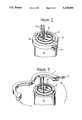
FIGS. 2 and 3 are more detailed perspective views of the end cap area showing removal of the end cap clamp;
FIGS. 4 and 5 are perspective views of the end cap area illustrating installation of the lifting handles and the immobilizing bars; and,
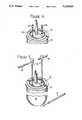
FIGS. 6 and 7 are side elevations illustrating removal of the end cap by a craftsperson.
Referring to FIG. 1, the light waveguide splice closure includes an ethylene-propylene copolymer container 10 holding a lightwaveguide splice tray 24.Container 10 is closed byend cap 12, which has a metallic surface 25 withincontainer 10. Also mounted incontainer 10 issilicone rubber vessel 21, which is shaped in the form of a pail having an open top with a flaredresilient brim 22. In use,brim 22 is in contact with the interior surface ofcontainer 10 to form a seal. Twolight waveguide cables 9 enterend cap 12 through holes which have been drilled therein. Sincepail 21 is betweenend cap 12 andsplice tray 24, light waveguides in buffer tubes 23 must proceed through the closed bottom ofvessel 21 in order to be spliced together insplice tray 24. This is facilitated by a series of circular areas 26 in the bottom ofvessel 21 of reduced thickness. In this manner, only a minimum number of areas 26 need to be breached equal to the number of light waveguide buffer tubes 23 which must pass to splicetray 24.Brim 22 and surface 25 ofend cap 12 are separated from each other by a distance of approximately one inch, which distance should preferably not exceed two inches. In actual use,vessel 21 will be filled up to surface 25 with an encapsulant which is a gel preventing access of water tosplice tray 24; however, the encapsulant is omitted from the drawings in order for the interior of the splice closure to be viewed.
Splice closure entry is described with reference to FIGS. 2-7. A clamp 11 is secured aroundend cap 12 by means ofclamp bolt 14. Whenbolt 14 is unscrewed, it swings outward in the direction of the arrow in FIG. 2 to allow removal of clamp 11 as shown in FIG. 3.
With reference to FIGS. 3 and 4, groundingbolts 13 are normally housed in threadedmetallic grounding lugs 20 which are provided by the prior art in the surface ofend cap 12. Afterbolts 13 are removed,rigid metal posts 16 are inserted intolugs 20 andlifting handles 18 are passed throughposts 16. In addition,bar 17 is passed throughhole 15 in a flange projecting slightly from the bottom ofcontainer 10. Afterbar 17 has been inserted, the craftsperson stands onbar 17 and lifts upwards onhandles 18 to removeend cap 12 from the container, as shown in FIGS. 6 and 7.
The unmodified splice closure (without the pail and lifting apparatus improvements) is available from RXS Schrumpftechnick-Garnituren GmbH. The lifting posts andhandles Pail 21 is resilient molded silicone rubber.
Claims (5)
1. A method for opening a light waveguide splice closure having a container and an end cap having hollow grounding lugs, comprising: immobilizing the container, affixing lifting handles to the hollow lugs in the end cap, and pulling on the lifting handles to remove the end cap from the container.
2. A light waveguide splice closure, comprising: a container having an end cap through which light waveguides may be inserted, said container holding splicing means for placing light waveguides into optical communication with each other and a vessel located between the end cap and the splicing means for holding encapsulant, said vessel having (1) an open top having a flared resilient brim forming a seal with the interior of the container and (2) a bottom having means for light waveguides to pass therethrough to the splicing means.
3. A light waveguide splice closure as recited in claim 2 wherein the vessel is made of resilient material.
4. A light waveguide splice closure as recited in claim 2 wherein the vessel brim is separated from the end cap by a distance of approximately one inch.
5. A light waveguide splice closure as recited in claim 2, further comprising at least one handle affixed to the exterior of said end cap.
Priority Applications (1)
| Application Number | Priority Date | Filing Date | Title |
|---|---|---|---|
| US07/888,068US5218664A (en) | 1992-05-26 | 1992-05-26 | Splice closure with lifting handles |
Applications Claiming Priority (1)
| Application Number | Priority Date | Filing Date | Title |
|---|---|---|---|
| US07/888,068US5218664A (en) | 1992-05-26 | 1992-05-26 | Splice closure with lifting handles |
Publications (1)
| Publication Number | Publication Date |
|---|---|
| US5218664Atrue US5218664A (en) | 1993-06-08 |
Family
ID=25392460
Family Applications (1)
| Application Number | Title | Priority Date | Filing Date |
|---|---|---|---|
| US07/888,068Expired - Fee RelatedUS5218664A (en) | 1992-05-26 | 1992-05-26 | Splice closure with lifting handles |
Country Status (1)
| Country | Link |
|---|---|
| US (1) | US5218664A (en) |
Cited By (34)
| Publication number | Priority date | Publication date | Assignee | Title |
|---|---|---|---|---|
| US5396575A (en)* | 1992-12-18 | 1995-03-07 | Raynet Corporation | Sealed optical fiber closures |
| US5422974A (en)* | 1994-09-23 | 1995-06-06 | The United States Of America As Represented By The Secretary Of The Navy | Shock resistant optic fiber rotary splice holding device |
| US5446823A (en)* | 1994-01-26 | 1995-08-29 | Raychem Corporation | Aerial, pedestal, below grade, or buried optical fiber closure |
| US5479554A (en)* | 1994-01-11 | 1995-12-26 | Windsor Communications | Splice closure apparatus for continuous optical ground wire communications cable and splicing system |
| US5499314A (en)* | 1994-11-22 | 1996-03-12 | Leite; Sara M. | Shock resistant optic fiber rotary splice holding device |
| DE29610075U1 (en)* | 1996-06-07 | 1996-08-22 | Alcatel Kabel AG & Co., 30179 Hannover | Hood sleeve for fiber optic earth or phase ropes |
| US5553186A (en)* | 1995-03-31 | 1996-09-03 | Minnesota Mining And Manufacturing Company | Fiber optic dome closure |
| US5596670A (en)* | 1993-12-09 | 1997-01-21 | Northern Telecom Limited | Optical fiber cable enclosure |
| US5633973A (en)* | 1994-12-08 | 1997-05-27 | Alcatel Cable Interface | Splice box for splicing together opticl-fiber cables |
| US5758004A (en)* | 1995-03-31 | 1998-05-26 | Minnesota Mining And Manufacturing Company | Closure with cable strain relief |
| US20030095774A1 (en)* | 2001-11-21 | 2003-05-22 | Alcatel | Optical waveguide termination |
| WO2002052304A3 (en)* | 2000-12-22 | 2003-08-21 | Corning Inc | Fiber optic spools and methods of making the same |
| US6628880B2 (en) | 2001-04-06 | 2003-09-30 | Windsor Communications, Inc. | Fiber optic cable splice enclosure |
| US20050207711A1 (en)* | 2004-03-19 | 2005-09-22 | Vo Chanh C | Optical termination pedestal |
| US7114727B1 (en)* | 2002-10-29 | 2006-10-03 | Mar Don Corporation | Seal assembly and method of forming seal |
| US20090060439A1 (en)* | 2007-09-05 | 2009-03-05 | Terry Dean Cox | Fiber optic terminal assembly |
| US20090211171A1 (en)* | 2008-02-25 | 2009-08-27 | Timothy Frederick Summers | Multi-dwelling unit multipurpose signal distribution apparatus |
| US20090297112A1 (en)* | 2004-03-08 | 2009-12-03 | Adc Telecommunications, Inc. | Fiber access terminal |
| US20100247053A1 (en)* | 2009-03-31 | 2010-09-30 | Cowen Andrew P | Removably mountable fiber optic terminal |
| US20110211799A1 (en)* | 2008-10-27 | 2011-09-01 | Mark Edward Conner | Variably configurable and modular local convergence point |
| US20110222831A1 (en)* | 2008-10-09 | 2011-09-15 | Songhua Cao | Fiber optic terminal having adapter panel supporting both input and output fibers from an optical splitter |
| US8467651B2 (en) | 2009-09-30 | 2013-06-18 | Ccs Technology Inc. | Fiber optic terminals configured to dispose a fiber optic connection panel(s) within an optical fiber perimeter and related methods |
| US8588571B1 (en)* | 2010-11-08 | 2013-11-19 | Google Inc. | Installation of fiber-to-the-premise using optical demarcation devices |
| US8655167B1 (en) | 2011-01-05 | 2014-02-18 | Google Inc. | Fiber diagnosis system for point-to-point optical access networks |
| US8781322B2 (en) | 2011-08-08 | 2014-07-15 | Google Inc. | Migratable wavelength division multiplexing passive optical network |
| US8792767B2 (en) | 2010-04-16 | 2014-07-29 | Ccs Technology, Inc. | Distribution device |
| US8909019B2 (en) | 2012-10-11 | 2014-12-09 | Ccs Technology, Inc. | System comprising a plurality of distribution devices and distribution device |
| US9004778B2 (en) | 2012-06-29 | 2015-04-14 | Corning Cable Systems Llc | Indexable optical fiber connectors and optical fiber connector arrays |
| US9049500B2 (en) | 2012-08-31 | 2015-06-02 | Corning Cable Systems Llc | Fiber optic terminals, systems, and methods for network service management |
| US9219546B2 (en) | 2011-12-12 | 2015-12-22 | Corning Optical Communications LLC | Extremely high frequency (EHF) distributed antenna systems, and related components and methods |
| US9547145B2 (en) | 2010-10-19 | 2017-01-17 | Corning Optical Communications LLC | Local convergence point for multiple dwelling unit fiber optic distribution network |
| US9547144B2 (en) | 2010-03-16 | 2017-01-17 | Corning Optical Communications LLC | Fiber optic distribution network for multiple dwelling units |
| US10110307B2 (en) | 2012-03-02 | 2018-10-23 | Corning Optical Communications LLC | Optical network units (ONUs) for high bandwidth connectivity, and related components and methods |
| US20200358272A1 (en)* | 2018-01-16 | 2020-11-12 | Commscope Technologies Llc | Telecommunications closures with gripping elements |
Citations (6)
| Publication number | Priority date | Publication date | Assignee | Title |
|---|---|---|---|---|
| US4666240A (en)* | 1985-02-01 | 1987-05-19 | Amp Incorporated | Splice organizer for optical cable splices |
| US4685764A (en)* | 1985-02-01 | 1987-08-11 | Amp Incorporated | Splice organizer for optical cable splices |
| US4799757A (en)* | 1987-04-21 | 1989-01-24 | Preformed Line Products Company | Encapsulated fiber optic closure |
| US5007701A (en)* | 1989-06-29 | 1991-04-16 | Windsor Communications, Inc. | Splice closure apparatus |
| US5097529A (en)* | 1991-03-22 | 1992-03-17 | At&T Bell Laboratories | Space-saving optical fiber cable closure |
| US5155794A (en)* | 1984-04-11 | 1992-10-13 | Raychem Corporation | Electrofit fibre optics butt splice |
- 1992
- 1992-05-26USUS07/888,068patent/US5218664A/ennot_activeExpired - Fee Related
Patent Citations (6)
| Publication number | Priority date | Publication date | Assignee | Title |
|---|---|---|---|---|
| US5155794A (en)* | 1984-04-11 | 1992-10-13 | Raychem Corporation | Electrofit fibre optics butt splice |
| US4666240A (en)* | 1985-02-01 | 1987-05-19 | Amp Incorporated | Splice organizer for optical cable splices |
| US4685764A (en)* | 1985-02-01 | 1987-08-11 | Amp Incorporated | Splice organizer for optical cable splices |
| US4799757A (en)* | 1987-04-21 | 1989-01-24 | Preformed Line Products Company | Encapsulated fiber optic closure |
| US5007701A (en)* | 1989-06-29 | 1991-04-16 | Windsor Communications, Inc. | Splice closure apparatus |
| US5097529A (en)* | 1991-03-22 | 1992-03-17 | At&T Bell Laboratories | Space-saving optical fiber cable closure |
Non-Patent Citations (4)
| Title |
|---|
| AT&T Practice Instruction sheet 633 502 101 9, 10 (1988).* |
| AT&T Practice Instruction sheet 633-502-101-9, 10 (1988). |
| Siecor Recommended Procedure SRP 003 255 (Jan. 1991).* |
| Siecor Recommended Procedure SRP 003-255 (Jan. 1991). |
Cited By (48)
| Publication number | Priority date | Publication date | Assignee | Title |
|---|---|---|---|---|
| US5396575A (en)* | 1992-12-18 | 1995-03-07 | Raynet Corporation | Sealed optical fiber closures |
| US5596670A (en)* | 1993-12-09 | 1997-01-21 | Northern Telecom Limited | Optical fiber cable enclosure |
| US5479554A (en)* | 1994-01-11 | 1995-12-26 | Windsor Communications | Splice closure apparatus for continuous optical ground wire communications cable and splicing system |
| US5446823A (en)* | 1994-01-26 | 1995-08-29 | Raychem Corporation | Aerial, pedestal, below grade, or buried optical fiber closure |
| US5422974A (en)* | 1994-09-23 | 1995-06-06 | The United States Of America As Represented By The Secretary Of The Navy | Shock resistant optic fiber rotary splice holding device |
| US5499314A (en)* | 1994-11-22 | 1996-03-12 | Leite; Sara M. | Shock resistant optic fiber rotary splice holding device |
| US5633973A (en)* | 1994-12-08 | 1997-05-27 | Alcatel Cable Interface | Splice box for splicing together opticl-fiber cables |
| US5553186A (en)* | 1995-03-31 | 1996-09-03 | Minnesota Mining And Manufacturing Company | Fiber optic dome closure |
| US5758004A (en)* | 1995-03-31 | 1998-05-26 | Minnesota Mining And Manufacturing Company | Closure with cable strain relief |
| DE29610075U1 (en)* | 1996-06-07 | 1996-08-22 | Alcatel Kabel AG & Co., 30179 Hannover | Hood sleeve for fiber optic earth or phase ropes |
| US6643445B2 (en) | 2000-12-22 | 2003-11-04 | Corning Incorporated | Fiber optic spools and methods of making the same |
| WO2002052304A3 (en)* | 2000-12-22 | 2003-08-21 | Corning Inc | Fiber optic spools and methods of making the same |
| US6628880B2 (en) | 2001-04-06 | 2003-09-30 | Windsor Communications, Inc. | Fiber optic cable splice enclosure |
| US20030095774A1 (en)* | 2001-11-21 | 2003-05-22 | Alcatel | Optical waveguide termination |
| US6690874B2 (en)* | 2001-11-21 | 2004-02-10 | Alcatel | Optical waveguide termination |
| US7114727B1 (en)* | 2002-10-29 | 2006-10-03 | Mar Don Corporation | Seal assembly and method of forming seal |
| US20090297112A1 (en)* | 2004-03-08 | 2009-12-03 | Adc Telecommunications, Inc. | Fiber access terminal |
| EP2267503A1 (en)* | 2004-03-08 | 2010-12-29 | ADC Telecommunications, Inc. | Fiber access terminal |
| US7941027B2 (en) | 2004-03-08 | 2011-05-10 | Adc Telecommunications, Inc. | Fiber access terminal |
| US8363999B2 (en) | 2004-03-08 | 2013-01-29 | Adc Telecommunications, Inc. | Fiber access terminal |
| US20050207711A1 (en)* | 2004-03-19 | 2005-09-22 | Vo Chanh C | Optical termination pedestal |
| US20090060439A1 (en)* | 2007-09-05 | 2009-03-05 | Terry Dean Cox | Fiber optic terminal assembly |
| US8798427B2 (en) | 2007-09-05 | 2014-08-05 | Corning Cable Systems Llc | Fiber optic terminal assembly |
| US20090211171A1 (en)* | 2008-02-25 | 2009-08-27 | Timothy Frederick Summers | Multi-dwelling unit multipurpose signal distribution apparatus |
| US20110222831A1 (en)* | 2008-10-09 | 2011-09-15 | Songhua Cao | Fiber optic terminal having adapter panel supporting both input and output fibers from an optical splitter |
| US9323020B2 (en) | 2008-10-09 | 2016-04-26 | Corning Cable Systems (Shanghai) Co. Ltd | Fiber optic terminal having adapter panel supporting both input and output fibers from an optical splitter |
| US8879882B2 (en) | 2008-10-27 | 2014-11-04 | Corning Cable Systems Llc | Variably configurable and modular local convergence point |
| US20110211799A1 (en)* | 2008-10-27 | 2011-09-01 | Mark Edward Conner | Variably configurable and modular local convergence point |
| US8520996B2 (en) | 2009-03-31 | 2013-08-27 | Corning Cable Systems Llc | Removably mountable fiber optic terminal |
| US20100247053A1 (en)* | 2009-03-31 | 2010-09-30 | Cowen Andrew P | Removably mountable fiber optic terminal |
| US8467651B2 (en) | 2009-09-30 | 2013-06-18 | Ccs Technology Inc. | Fiber optic terminals configured to dispose a fiber optic connection panel(s) within an optical fiber perimeter and related methods |
| US9547144B2 (en) | 2010-03-16 | 2017-01-17 | Corning Optical Communications LLC | Fiber optic distribution network for multiple dwelling units |
| US8792767B2 (en) | 2010-04-16 | 2014-07-29 | Ccs Technology, Inc. | Distribution device |
| US9720197B2 (en) | 2010-10-19 | 2017-08-01 | Corning Optical Communications LLC | Transition box for multiple dwelling unit fiber optic distribution network |
| US9547145B2 (en) | 2010-10-19 | 2017-01-17 | Corning Optical Communications LLC | Local convergence point for multiple dwelling unit fiber optic distribution network |
| US8588571B1 (en)* | 2010-11-08 | 2013-11-19 | Google Inc. | Installation of fiber-to-the-premise using optical demarcation devices |
| US9240855B1 (en) | 2011-01-05 | 2016-01-19 | Google Inc. | Fiber diagnosis system for point-to-point optical access networks |
| US8655167B1 (en) | 2011-01-05 | 2014-02-18 | Google Inc. | Fiber diagnosis system for point-to-point optical access networks |
| US8781322B2 (en) | 2011-08-08 | 2014-07-15 | Google Inc. | Migratable wavelength division multiplexing passive optical network |
| US9219546B2 (en) | 2011-12-12 | 2015-12-22 | Corning Optical Communications LLC | Extremely high frequency (EHF) distributed antenna systems, and related components and methods |
| US9602209B2 (en) | 2011-12-12 | 2017-03-21 | Corning Optical Communications LLC | Extremely high frequency (EHF) distributed antenna systems, and related components and methods |
| US9800339B2 (en) | 2011-12-12 | 2017-10-24 | Corning Optical Communications LLC | Extremely high frequency (EHF) distributed antenna systems, and related components and methods |
| US10110305B2 (en) | 2011-12-12 | 2018-10-23 | Corning Optical Communications LLC | Extremely high frequency (EHF) distributed antenna systems, and related components and methods |
| US10110307B2 (en) | 2012-03-02 | 2018-10-23 | Corning Optical Communications LLC | Optical network units (ONUs) for high bandwidth connectivity, and related components and methods |
| US9004778B2 (en) | 2012-06-29 | 2015-04-14 | Corning Cable Systems Llc | Indexable optical fiber connectors and optical fiber connector arrays |
| US9049500B2 (en) | 2012-08-31 | 2015-06-02 | Corning Cable Systems Llc | Fiber optic terminals, systems, and methods for network service management |
| US8909019B2 (en) | 2012-10-11 | 2014-12-09 | Ccs Technology, Inc. | System comprising a plurality of distribution devices and distribution device |
| US20200358272A1 (en)* | 2018-01-16 | 2020-11-12 | Commscope Technologies Llc | Telecommunications closures with gripping elements |
Similar Documents
| Publication | Publication Date | Title |
|---|---|---|
| US5218664A (en) | Splice closure with lifting handles | |
| US5754724A (en) | Fiber optic support apparatus | |
| EP0367477B1 (en) | Optical fiber cable closure | |
| US20200003984A1 (en) | Cable clamp and telecommunications enclosure | |
| AU659959B2 (en) | Cable closure which includes a cable sheath gripping assembly | |
| US5479553A (en) | Fiber optic splice closure | |
| US5696351A (en) | Cable retention and sealing device | |
| CA2085271A1 (en) | Optical fiber closure | |
| CA2129153A1 (en) | Cable Splice Protector | |
| US20070256848A1 (en) | Telecommunications cable enclosure | |
| GB2014644A (en) | Cable Clip for Variable Cable Diameters | |
| EP0824468B1 (en) | Over-center closing device | |
| GB2299409A (en) | Clamps for tube and optical fibre in it | |
| US4924034A (en) | Re-enterable enclosure around splice | |
| US7268299B2 (en) | Telecommunications cable enclosure | |
| US6329601B1 (en) | Service wire splice housing | |
| DE69403787D1 (en) | Container closure device | |
| NO171934B (en) | FIBEROPTICAL SKATE HOUSE | |
| US11852883B2 (en) | Cable clamp and telecommunications enclosure | |
| US5859388A (en) | Splice closure | |
| EP0352484A2 (en) | Cable coupler | |
| GB2296393A (en) | Cable splice closure box and cable clamp | |
| GB2298053A (en) | An optical fibre management system | |
| US5387763A (en) | Enclosure for straight cable splice | |
| GB2275786A (en) | C-shaped optical fibre splice storage tray |
Legal Events
| Date | Code | Title | Description |
|---|---|---|---|
| AS | Assignment | Owner name:SIECOR CORPORATION A CORP. OF DELAWARE, NORTH CA Free format text:ASSIGNMENT OF ASSIGNORS INTEREST.;ASSIGNORS:O'NEILL, ANDREW J.;HARVEY, JOHN D.;MERRIKEN, JAMES R.;REEL/FRAME:006141/0582 Effective date:19920513 | |
| FPAY | Fee payment | Year of fee payment:4 | |
| AS | Assignment | Owner name:SIECOR CORPORATION, NORTH CAROLINA Free format text:ASSIGNMENT OF ASSIGNORS INTEREST;ASSIGNOR:NORTHERN TELECOM LIMITED;REEL/FRAME:008943/0673 Effective date:19941230 | |
| AS | Assignment | Owner name:SIECOR TECHNOLOGY, INC., DELAWARE Free format text:ASSIGNMENT OF ASSIGNORS INTEREST;ASSIGNOR:SIECOR CORPORATION;REEL/FRAME:008955/0764 Effective date:19971031 | |
| REMI | Maintenance fee reminder mailed | ||
| LAPS | Lapse for failure to pay maintenance fees | ||
| FP | Lapsed due to failure to pay maintenance fee | Effective date:20010608 | |
| STCH | Information on status: patent discontinuation | Free format text:PATENT EXPIRED DUE TO NONPAYMENT OF MAINTENANCE FEES UNDER 37 CFR 1.362 |