US5218515A - Microchannel cooling of face down bonded chips - Google Patents
Microchannel cooling of face down bonded chipsDownload PDFInfo
- Publication number
- US5218515A US5218515AUS07/850,634US85063492AUS5218515AUS 5218515 AUS5218515 AUS 5218515AUS 85063492 AUS85063492 AUS 85063492AUS 5218515 AUS5218515 AUS 5218515A
- Authority
- US
- United States
- Prior art keywords
- integrated circuit
- chip
- circuit board
- coolant
- grooves
- Prior art date
- Legal status (The legal status is an assumption and is not a legal conclusion. Google has not performed a legal analysis and makes no representation as to the accuracy of the status listed.)
- Expired - Lifetime
Links
- 238000001816coolingMethods0.000titleabstractdescription30
- 239000002826coolantSubstances0.000claimsabstractdescription89
- 229920001971elastomerPolymers0.000claimsabstractdescription14
- 239000000806elastomerSubstances0.000claimsabstractdescription14
- 239000000758substrateSubstances0.000claimsdescription14
- 238000004891communicationMethods0.000claimsdescription6
- 230000013011matingEffects0.000claimsdescription5
- 239000010409thin filmSubstances0.000claimsdescription4
- 238000000034methodMethods0.000abstractdescription10
- 229910000679solderInorganic materials0.000description11
- 238000005516engineering processMethods0.000description9
- 238000004519manufacturing processMethods0.000description6
- 239000004020conductorSubstances0.000description4
- 238000010586diagramMethods0.000description3
- 239000011521glassSubstances0.000description3
- 239000000463materialSubstances0.000description3
- XUIMIQQOPSSXEZ-UHFFFAOYSA-NSiliconChemical group[Si]XUIMIQQOPSSXEZ-UHFFFAOYSA-N0.000description2
- 230000008878couplingEffects0.000description2
- 238000010168coupling processMethods0.000description2
- 238000005859coupling reactionMethods0.000description2
- 230000005496eutecticsEffects0.000description2
- 239000007788liquidSubstances0.000description2
- 238000012986modificationMethods0.000description2
- 230000004048modificationEffects0.000description2
- 239000003566sealing materialSubstances0.000description2
- 229910052710siliconInorganic materials0.000description2
- 239000010703siliconSubstances0.000description2
- XLYOFNOQVPJJNP-UHFFFAOYSA-NwaterSubstancesOXLYOFNOQVPJJNP-UHFFFAOYSA-N0.000description2
- 229920002449FKMPolymers0.000description1
- 238000013459approachMethods0.000description1
- 230000006835compressionEffects0.000description1
- 238000007906compressionMethods0.000description1
- 239000012809cooling fluidSubstances0.000description1
- 239000000112cooling gasSubstances0.000description1
- 239000012530fluidSubstances0.000description1
- 230000017525heat dissipationEffects0.000description1
- 229910001338liquidmetalInorganic materials0.000description1
- 239000003921oilSubstances0.000description1
- 238000004806packaging method and processMethods0.000description1
- 230000003071parasitic effectEffects0.000description1
- 229920001084poly(chloroprene)Polymers0.000description1
- 238000012552reviewMethods0.000description1
- -1silicate esterChemical class0.000description1
- 229920002545silicone oilPolymers0.000description1
- 239000007787solidSubstances0.000description1
- 239000002470thermal conductorSubstances0.000description1
Images


Classifications
- H—ELECTRICITY
- H01—ELECTRIC ELEMENTS
- H01L—SEMICONDUCTOR DEVICES NOT COVERED BY CLASS H10
- H01L23/00—Details of semiconductor or other solid state devices
- H01L23/34—Arrangements for cooling, heating, ventilating or temperature compensation ; Temperature sensing arrangements
- H01L23/46—Arrangements for cooling, heating, ventilating or temperature compensation ; Temperature sensing arrangements involving the transfer of heat by flowing fluids
- H01L23/473—Arrangements for cooling, heating, ventilating or temperature compensation ; Temperature sensing arrangements involving the transfer of heat by flowing fluids by flowing liquids
- F—MECHANICAL ENGINEERING; LIGHTING; HEATING; WEAPONS; BLASTING
- F28—HEAT EXCHANGE IN GENERAL
- F28F—DETAILS OF HEAT-EXCHANGE AND HEAT-TRANSFER APPARATUS, OF GENERAL APPLICATION
- F28F2260/00—Heat exchangers or heat exchange elements having special size, e.g. microstructures
- F28F2260/02—Heat exchangers or heat exchange elements having special size, e.g. microstructures having microchannels
- H—ELECTRICITY
- H01—ELECTRIC ELEMENTS
- H01L—SEMICONDUCTOR DEVICES NOT COVERED BY CLASS H10
- H01L2924/00—Indexing scheme for arrangements or methods for connecting or disconnecting semiconductor or solid-state bodies as covered by H01L24/00
- H01L2924/0001—Technical content checked by a classifier
- H01L2924/0002—Not covered by any one of groups H01L24/00, H01L24/00 and H01L2224/00
Definitions
- the present inventionrelates to cooling high power integrated circuits; and particularly to microchannel cooling of integrated circuits bonded face down on circuit boards, such as by flip-chip bonding.
- thermal conduction modulesuch as described in the Goldman, et al. article cited above.
- TCMthermal conduction module
- the thermal conduction modulesare very complex mechanically, and can only remove limited amounts of heat. As the power dissipated by integrated circuits increases, it is expected that the thermal conduction module technology will be insufficient.
- Microchannel coolingis described in detail in Tuckerman, et al., "High-Performance Heat Sinking for VLSI", IEEE ELECTRON DEVICE LETTERS, Vol. EDL-2, No. 5, May, 1981, pp. 126-129; Tuckerman, et al., U.S. Pat. No. 4,450,472; and Phillips, et al., U.S. Pat. No. 4,894,790.
- a grooved cooling moduleis bonded to a suction plate.
- the cooling moduleis coupled through a bellows-type tube to a manifold for delivering coolant to the structure.
- the suction platecontacts the backside of the integrated circuits through a silicone oil or other liquid, providing a suction joint at which the integrated circuit may be separated from the cooling structure.
- the Yamada, et al. structureillustrates the mechanical complexity of supplying a flow of coolant through a microchannel structure that is in close thermal contact with an integrated circuit chip mounted face down on a circuit board.
- the integrated circuit chipswill not lie perfectly flat on the circuit board, and will lay at varying heights, due to the manufacturing tolerances of flip-chip bonding.
- Yamada, et al.has devised this suction plate approach to making a good thermal contact with the chip.
- the suction plate envisioned by Yamada, et alrequires use of a liquid which is a poor conductor of heat (in the case of oil) or which can contaminate and electrically short circuit the integrated circuits (in the case of liquid metals), and is believed to have other limitations which render it impractical.
- the present inventionprovides a technique for applying microchannel cooling to flip-chip bonded integrated circuits, which maintains all of the advantages of flip-chip bond, while overcoming the difficulties encountered in cooling the chips. Furthermore, the technique is suited to either multichip integrated circuit boards in a plane, or to stacks of circuit boards, in a three dimensional interconnect structure.
- an integrated circuit packagecomprises a circuit board, and an integrated circuit chip having an integrated circuit formed on a first major surface.
- the chipis mounted on the circuit board so that the first major surface faces the circuit board using bonds, such as flip-chip or control collapse bonds.
- a microchannel structureis essentially permanently coupled with the second major surface of the chip, and provides a coolant flow path in heat flow communication with the chip.
- a coolant delivery manifolddelivers coolant to the microchannel structure, and a removable, compressible seal is provided between the coolant delivery manifold and the microchannel structure.
- the microchannel structuremay comprise a grooved substrate bonded to the second major surface of the integrated circuit chip, with a cover manifold over the grooved substrate providing a coolant flow path through the grooves.
- the microchannel structuremay comprise a plurality of grooves formed in the second major surface of the integrated circuit chip, and a corresponding cover manifold.
- the seal in a preferred systemcomprises a compressible elastomer, so that coupling of the coolant delivery manifold to the microchannel structure may be securely made while tolerating differences in height of the integrated circuit chips, and without requiring large pressures which may damage the chips.
- the packageallows for removal and replacement of individual integrated circuit modules.
- a failed integrated circuitmay be detected and located on a circuit board.
- the coolant supply manifoldmay be easily removed.
- the sealitself may be removable, or it may be affixed to either the manifold or the microchannel structure. This exposes flip-chip bonded integrated circuit modules that may be selectively removed and replaced using standard flip-chip bonding techniques. The seal and coolant supply manifold are then replaced and the structure is made whole again.
- the packagecomprises a stack of circuit boards, having flip-chip bonded integrated circuit modules as described above mounted on circuit boards in the stack.
- the coolant supply manifoldsare disposed between the circuit boards and coupled to supplies of coolant at a side of the stack.
- a replaceable integrated circuit module as described aboveis provided.
- FIG. 1is a schematic diagram of a stack of circuit boards with a coolant supply manifold according to the present invention.
- FIG. 2is a cross-section view of a multi-chip module with flip-chip bonding and individual chip micro-channel cooling.
- FIG. 3is a cross-section view of an alternative technique for bonding the perimeter walls on the multi-chip modules using solder bump technology.
- FIG. 4is a cross-section view of an alternative multi-chip module with a microchannel cooling system adapted for air as the coolant.
- FIG. 5is a cross-section view of an integrated circuit module with microchannel cooling, taken along the microchannel according to one embodiment of the present invention.
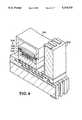
- FIG. 6is a perspective view of an integrated circuit module sectioned in two perpendicular directions with microchannel cooling according to the present invention.
- FIG. 7is a schematic diagram of a multichip module with microchannel cooled integrated circuit modules on the circuit board.
- FIG. 8is a schematic diagram of a coolant supply manifold for use with the multichip module of FIG. 7.
- FIGS. 1-8illustrate embodiments of the present invention using "flip-chip” bonded integrated circuits with microchannel cooling on the top side of the integrated circuits.
- FIG. 1schematically illustrates a stack 10 of circuit boards 11-17.
- the circuit boards 11-17are separated by perimeter wall members 18-23.
- the top circuit board 11also has a perimeter wall member 24 bonded along the side for structural purposes. Such wall may or may not be necessary for a given embodiment.
- the integrated circuit stackis implemented in the preferred embodiment according to the technology described in the above-referenced U.S. patent application entitled “THREE DIMENSIONAL, MULTI-CHIP MODULE", which is incorporated by reference in the present application as if fully set forth herein.
- a plurality of integrated circuitssuch as integrated circuit 30, are mounted on each circuit board using face down bonding, such as flip-chip technology.
- a coolant delivery manifold 31is coupled at a compressible seal 32 to the individual integrated circuits.
- the coolant delivery manifoldis, in turn, connected through tube 33 to a source 34 of coolant.
- a coolant input 35 and a coolant output 36are used to provide the flow of coolant for the entire stack 10.
- each of the individual circuit boards in the stackincludes its own coolant delivery manifold as evidenced by the tubes 37, 38, 33, 39, 40, 41, and 42.
- the input and output ports for the coolant delivery manifoldsare provided on the same side of the stack.
- Alternative systemsmay have an input manifold on one side and an output manifold on an opposite side, or other configurations as suit the particular mounting technology used for the stack.
- FIG. 1illustrates that the present invention is particularly suited for three dimensional stacks of circuit boards using flip-chip bonding techniques
- the present inventionis also well suited for a single, planar circuit board embodiment, or other geometries as may suit a particular application.
- FIGS. 2-8More details concerning the microchannel cooling structure according to the present invention are provided with respect to FIGS. 2-8.
- FIG. 2shows a cross-sectional view of an integrated circuit chip 125, circuit board 120, perimeter wall 131, and coolant supply manifold 129 (sectioned in the Figure through a coolant supply channel 133), for a face down mounted integrated circuit package according to the present invention.
- each circuit board 120has a first major surface 121 and a second major surface 122. Near the first major surface 121 of the circuit board 120, a thin film, planarized interconnect 123 is formed.
- the interconnect 123has chip bonding sites (e.g., 124) accessible at the first major surface.
- the chip bonding sitesare adapted for flip-chip, solder bump, or controlled-collapse bonding to corresponding bonding sites on the integrated circuit chip 125.
- a substrate 126having a plurality of grooves (e.g., 127).
- a groove cover 128is bonded to the grooved substrate 126 providing cooling channels along the grooves 127 in the substrate 126. Openings in groove cover 128 are provided at each end of the grooves 127 so that a coolant flow path is provided along the grooves.
- the chip, grooves, and groove coverare connected together to provide a replaceable integrated circuit module.
- a coolant supply manifold 129is then coupled to the groove cover 128 using a compressible elastomer seal 130.
- the compressible elastomer seal 130surrounds openings in the coolant supply manifold at each end of the grooves 127 to confine flow of the coolant through the channels formed by the grooves. Also, the compressible elastomer seal 130 has sufficient thickness to account for variations in height of the chips due to manufacturing tolerances or other variations.
- the perimeter wall 131 for the module formed with the microchannel coolinghas a height greater than the combined height of the flip-chip mounted integrated circuit 125, the microchannel groove substrate 126, the groove cover 128, the elastomer seal 130, and the coolant supply manifold 129.
- heat dissipationis assumed to be 150 W/cm 2 on 12 ⁇ 12 mm chips; the coolant supply channel 133 is sized to cool a pair of rows of 10 chips each using water as the coolant.
- the resulting perimeter wall heightis about 7 mm. This perimeter wall is bonded using a eutectic bond 132.
- the coolant used in the microchannel cooling system of FIG. 2can be water, a dielectric fluid such as Coolanol (a silicate ester available from Monsanto, St. Louis, Mo.), air, or other cooling fluid or gas. Coolants with a large heat capacity and thermal conductivity allow for implementation with smaller dimensions to facilitate dense integrated circuit packaging.
- Coolanola silicate ester available from Monsanto, St. Louis, Mo.
- Laser-patterned interconnects along the sides of the circuit board 120 and up the sides of the perimeter wall 131are provided.
- FIG. 3illustrates an alternative technique for mounting the perimeter wall 140 on a circuit board 141.
- controlled-collapse, or solder bump bondingis used on both the top and bottom surfaces to mount the perimeter wall 140 on the circuit board, in the same manner as the chips 142 are mounted on the circuit board 141.
- the planar interconnectwill include a bonding site 143 adapted for solder bump bonding to the conductors 144 on the perimeter wall.
- Conductorswrap around three sides of the perimeter wall and are formed using laser pantography. In this embodiment, the laser pantography is carried out in two steps, forming conductors around the bottom corner 145 in a first step and a top corner 146 in a second step.
- FIG. 4illustrates an example of an embodiment adapted for air cooling of pairs of rows of 10 chips each, where the chips generate about 20 W/cm 2 .
- the perimeter wall 200may be approximately 10 mm high. This allows for a coolant supply manifold 201 approximately 5 mm high and an integrated circuit module 202, which includes the integrated circuit 203, the grooved substrate 204, and the cover 205, of approximately 3 mm in height.
- FIG. 5provides a cross-sectional view of an integrated circuit module, generally 299, and coolant supply manifold 310 apart from the stacked interconnect system.
- each module 299includes an integrated circuit chip 300 having a plurality of solder bump bonding sites (e.g., 301, 302) formed on a first major surface 303 of the chip 300. Also on the first major surface 303 an integrated circuit is formed on the chip.
- the backside 304 of the integrated circuit chipis bonded to a microchannel structure 305 which includes a plurality of grooves 306.
- a microchannel cover manifold 307is bonded to the microchannel structure 305.
- the cover manifold 307is manufactured using glass or other material compatible with bonding to the microchannel structure 305.
- a glass covermay be bonded to a silicon microchannel heat sink using hot contact bonding.
- the cover manifold 307includes coolant delivery channels 308, 309 which provide a coolant flow path through the cover manifold 307 to the grooves 306 in the microchannel structure 305.
- the coolant delivery channels 308, 309are fed coolant through a coolant supply manifold 310.
- the coolant supply manifold 310includes a first flow path 311, and a second flow path 312.
- the first flow path 311provides higher pressure coolant into the coolant delivery channel 308, while the flow path 312 provides a lower pressure path from the coolant delivery channel 309.
- An elastomer seal 313seals the junction between the flow path 311 and the coolant delivery channel 308, and elastomer seal 314 seals the junction between the coolant delivery channel 309 and the coolant flow path 312.
- the elastomer seals 313, 314consist of a compressible material, such as neoprene, viton, or the like, which allows the coolant supply manifold 310 to be placed over the chip module 299 of FIG. 5 with sufficient pressure to form a seal for the coolant flow while allowing for differences in height of the integrated circuit modules on a given circuit board that arise due to manufacturing tolerances, warping, and the like.
- FIG. 6illustrates a cut-away perspective view of an integrated circuit module, generally, 350 according to the invention.
- the integrated circuit module 350includes an integrated circuit chip 351 having solder bump bonding sites 352 along a first major surface 353 of the chip.
- the back surface 354 of the chip 351is bonded to a microchannel structure 355.
- a plurality of microchannels 356are formed in the microchannel structure 355.
- the cover manifold 357is bonded to the microchannel structure 355.
- the coolant delivery channel 358is cut or formed in the cover manifold 357 as illustrated.
- the coolant supply manifold (310 of FIG. 5)is removable, and the solder bump bonding allows removal of each chip module individually, the present technique allows implementation of microchannel cooling on a chip by chip basis in a large circuit board. Furthermore, upon failure of an individual chip on the circuit board, the coolant supply manifold 310 can be removed, and individual integrated circuit modules 350 can be replaced as necessary.
- FIGS. 7 and 8schematically illustrate a circuit board module 400 and a coolant supply manifold 401 for use with the microchannel cooled IC modules of FIGS. 5 and 6.
- the circuit board module 400includes a circuit board 402 having a first major surface 403.
- a plurality of integrated circuit modulese.g., 404, 405 are bonded to the circuit board 403 using flip-chip, or other face down bonding technology.
- Each of the integrated circuit modulesincludes an integrated circuit, a microchannel structure, and a cover manifold.
- An elastomer seal 406, 407is provided around each of the coolant delivery openings 408, 409 in the coolant cover manifolds.
- a perimeter wall 416 around the circuit board 402. Perimeter wall 416may be implemented as illustrated in FIGS. 2, 3, or 4 to provide for an efficient interconnect structure in a stack of individually microchannel cooled integrated circuit modules.
- the coolant supply manifold 401(FIG. 8) includes a plurality of coolant supply channels (e.g., 410, 411, 412, 413). Channels 410 and 412 are higher pressure channels while channels 411 and 413 are lower pressure channels.
- the manifold 401is adapted for placement over the printed circuit board module of FIG. 7 so that the openings (e.g., 414, 415) in the coolant supply channels (e.g., 410, 411) mate with the openings (e.g., 408, 409) in the individual integrated circuit modules (e.g., 404) on the circuit board 400.
- the elastomer seals 406 and 407permit the coupling of the coolant supply manifold 401 with the integrated circuit modules 404 while accounting for manufacturing tolerances and preventing large forces on the integrated circuit which may lead to cracks or other failures in the devices.
- a dieis attached to a microchannel heat sink, bonded to a cover manifold to establish a coolant flow path through the grooves in the microchannel heat sink.
- the heat sinkmay be made using silicon or other materials, with a cover manifold of glass.
- the integrated circuitis attached to the heat sink structure using a eutectic or other solder bond.
- the groove structureis formed directly in the back of the integrated circuit chip. This integrated circuit module may then be bonded face down to a circuit board.
- a separate coolant supply manifoldis provided.
- the coolant supply manifoldis big enough in lateral dimensions to cover all or a subset of the integrated circuit modules on a given circuit board. For instance, a single coolant supply manifold may supply more than 100 chips per board.
- the coolant supply manifoldhas a number of coolant supply and removal lines, with holes or slots in the bottom which mate to the input and output structures on the respective integrated circuit modules. These mating contacts are surrounded by a sealing material to prevent leaks.
- the sealing materialis sufficiently compliant, and elastic to allow for a range of compression. This range accommodates the difference in height of the various integrated circuit modules.
- the coolant supply manifoldcan be attached or otherwise referenced to the circuit board or the circuit board holder. Tolerances in manufacturing this structure are quite lax, perhaps 0.2 mm out of 200 mm.
Landscapes
- Physics & Mathematics (AREA)
- Condensed Matter Physics & Semiconductors (AREA)
- General Physics & Mathematics (AREA)
- Engineering & Computer Science (AREA)
- Computer Hardware Design (AREA)
- Microelectronics & Electronic Packaging (AREA)
- Power Engineering (AREA)
- Cooling Or The Like Of Semiconductors Or Solid State Devices (AREA)
Abstract
Description
Claims (23)
Priority Applications (4)
| Application Number | Priority Date | Filing Date | Title |
|---|---|---|---|
| US07/850,634US5218515A (en) | 1992-03-13 | 1992-03-13 | Microchannel cooling of face down bonded chips |
| JP5515867AJPH07504538A (en) | 1992-03-13 | 1993-03-08 | Microchannel cooling of face-down bonding chips |
| PCT/US1993/001928WO1993018548A1 (en) | 1992-03-13 | 1993-03-08 | Microchannel cooling of face down bonded chips |
| EP93907183AEP0630522A4 (en) | 1992-03-13 | 1993-03-08 | MICROCHANNEL COOLING OF CONNECTED CHIPS FACE DOWN. |
Applications Claiming Priority (1)
| Application Number | Priority Date | Filing Date | Title |
|---|---|---|---|
| US07/850,634US5218515A (en) | 1992-03-13 | 1992-03-13 | Microchannel cooling of face down bonded chips |
Publications (1)
| Publication Number | Publication Date |
|---|---|
| US5218515Atrue US5218515A (en) | 1993-06-08 |
Family
ID=25308707
Family Applications (1)
| Application Number | Title | Priority Date | Filing Date |
|---|---|---|---|
| US07/850,634Expired - LifetimeUS5218515A (en) | 1992-03-13 | 1992-03-13 | Microchannel cooling of face down bonded chips |
Country Status (4)
| Country | Link |
|---|---|
| US (1) | US5218515A (en) |
| EP (1) | EP0630522A4 (en) |
| JP (1) | JPH07504538A (en) |
| WO (1) | WO1993018548A1 (en) |
Cited By (86)
| Publication number | Priority date | Publication date | Assignee | Title |
|---|---|---|---|---|
| WO1996027280A1 (en)* | 1995-03-02 | 1996-09-06 | Intel Corporation | Thermally and electrically enhanced ball grid package |
| US5735196A (en)* | 1996-05-29 | 1998-04-07 | Ibm Corporation | Apparatus for applying a force to laminated integrated circuit devices |
| US5772835A (en)* | 1996-05-29 | 1998-06-30 | Ibm Corporation | Vacuum oven chamber for making laminated integrated circuit devices |
| US5772815A (en)* | 1996-05-29 | 1998-06-30 | International Business Machines Corporation | Method for making laminated integrated circuit devices |
| US5801442A (en)* | 1996-07-22 | 1998-09-01 | Northrop Grumman Corporation | Microchannel cooling of high power semiconductor devices |
| US5813113A (en)* | 1996-12-09 | 1998-09-29 | International Business Machines Corporation | Fixture for making laminated integrated circuit devices |
| US5870823A (en)* | 1996-11-27 | 1999-02-16 | International Business Machines Corporation | Method of forming a multilayer electronic packaging substrate with integral cooling channels |
| US5892203A (en)* | 1996-05-29 | 1999-04-06 | International Business Machines Corporation | Apparatus for making laminated integrated circuit devices |
| US5901037A (en)* | 1997-06-18 | 1999-05-04 | Northrop Grumman Corporation | Closed loop liquid cooling for semiconductor RF amplifier modules |
| US6187412B1 (en) | 1997-06-27 | 2001-02-13 | International Business Machines Corporation | Silicon article having columns and method of making |
| US6242778B1 (en) | 1998-09-22 | 2001-06-05 | International Business Machines Corporation | Cooling method for silicon on insulator devices |
| US6433413B1 (en)* | 2001-08-17 | 2002-08-13 | Micron Technology, Inc. | Three-dimensional multichip module |
| US6440770B1 (en) | 1996-09-09 | 2002-08-27 | Intel Corporation | Integrated circuit package |
| US20020124961A1 (en)* | 2001-02-28 | 2002-09-12 | Porter George K. | Manifolded fluid delivery system |
| US20030085024A1 (en)* | 2001-09-28 | 2003-05-08 | Santiago Juan G | Control of electrolysis gases in electroosmotic pump systems |
| US6591625B1 (en) | 2002-04-17 | 2003-07-15 | Agilent Technologies, Inc. | Cooling of substrate-supported heat-generating components |
| US6606251B1 (en) | 2002-02-07 | 2003-08-12 | Cooligy Inc. | Power conditioning module |
| US20030178178A1 (en)* | 2000-04-11 | 2003-09-25 | Norbert Breuer | Cooling device for cooling components of the power electronics, said device comprising a micro heat exchanger |
| US6629425B2 (en) | 2000-07-24 | 2003-10-07 | Micron Technology, Inc. | MEMS heat pumps for integrated circuit heat dissipation |
| US6679315B2 (en) | 2002-01-14 | 2004-01-20 | Marconi Communications, Inc. | Small scale chip cooler assembly |
| US20040046243A1 (en)* | 1998-09-15 | 2004-03-11 | Carapella Elissa E. | Methods of split cavity wall plating for an integrated circuit package |
| US6713866B2 (en) | 2002-04-22 | 2004-03-30 | Agilent Technologies, Inc. | Cooling of optoelectronic elements |
| US20040089442A1 (en)* | 2001-09-28 | 2004-05-13 | The Board Of Trustees Of The Leland Stanford Junior University | Electroosmotic microchannel cooling system |
| US20040101421A1 (en)* | 2002-09-23 | 2004-05-27 | Kenny Thomas W. | Micro-fabricated electrokinetic pump with on-frit electrode |
| US20040104022A1 (en)* | 2002-11-01 | 2004-06-03 | Cooligy, Inc. | Method and apparatus for flexible fluid delivery for cooling desired hot spots in a heat producing device |
| US20040104012A1 (en)* | 2002-10-22 | 2004-06-03 | Cooligy, Inc. | Vapor escape microchannel heat exchanger |
| US20040148959A1 (en)* | 2003-01-31 | 2004-08-05 | Cooligy, Inc. | Remedies to prevent cracking in a liquid system |
| US20040182548A1 (en)* | 2003-03-17 | 2004-09-23 | Cooligy, Inc. | Multi-level microchannel heat exchangers |
| US20040182560A1 (en)* | 2003-03-17 | 2004-09-23 | Cooligy Inc. | Apparatus and method of forming channels in a heat-exchanging device |
| US20040182551A1 (en)* | 2003-03-17 | 2004-09-23 | Cooligy, Inc. | Boiling temperature design in pumped microchannel cooling loops |
| US20040188066A1 (en)* | 2002-11-01 | 2004-09-30 | Cooligy, Inc. | Optimal spreader system, device and method for fluid cooled micro-scaled heat exchange |
| US20040188065A1 (en)* | 2003-01-31 | 2004-09-30 | Cooligy, Inc. | Decoupled spring-loaded mounting apparatus and method of manufacturing thereof |
| US20040207061A1 (en)* | 2001-08-30 | 2004-10-21 | Farrar Paul A. | Multi-chip electronic package and cooling system |
| US20040206477A1 (en)* | 2002-11-01 | 2004-10-21 | Cooligy, Inc. | Method and apparatus for efficient vertical fluid delivery for cooling a heat producing device |
| US20040212965A1 (en)* | 2003-03-17 | 2004-10-28 | Toshiaki Ishii | Electronic circuit apparatus and method of manufacturing the same |
| US20040244950A1 (en)* | 2003-01-31 | 2004-12-09 | Cooligy, Inc. | Optimized multiple heat pipe blocks for electronics cooling |
| US20050068725A1 (en)* | 2003-09-30 | 2005-03-31 | Sabina Houle | Thermal management systems for micro-components |
| US20050110145A1 (en)* | 2003-11-20 | 2005-05-26 | Kai-Erik Elers | Multilayer metallization |
| US20050254539A1 (en)* | 2004-05-17 | 2005-11-17 | Klimek Daniel E | Staggered array coupler |
| US20050269061A1 (en)* | 2004-06-04 | 2005-12-08 | Cooligy, Inc. | Apparatus and method of efficient fluid delivery for cooling a heat producing device |
| US20060002086A1 (en)* | 2004-06-30 | 2006-01-05 | Teneketges Nicholas J | Heat exchange apparatus with parallel flow |
| US20060002087A1 (en)* | 2004-07-01 | 2006-01-05 | Bezama Raschid J | Apparatus and methods for microchannel cooling of semiconductor integrated circuit packages |
| US20060002088A1 (en)* | 2004-07-01 | 2006-01-05 | Bezama Raschid J | Apparatus and methods for microchannel cooling of semiconductor integrated circuit packages |
| US6986382B2 (en) | 2002-11-01 | 2006-01-17 | Cooligy Inc. | Interwoven manifolds for pressure drop reduction in microchannel heat exchangers |
| US7021369B2 (en) | 2003-07-23 | 2006-04-04 | Cooligy, Inc. | Hermetic closed loop fluid system |
| US20060096738A1 (en)* | 2004-11-05 | 2006-05-11 | Aavid Thermalloy, Llc | Liquid cold plate heat exchanger |
| US20060126293A1 (en)* | 2004-12-09 | 2006-06-15 | International Business Machines Corporation | Cooling apparatus for an electronics subsystem employing a coolant flow drive apparatus between coolant flow paths |
| US20060180924A1 (en)* | 2004-11-12 | 2006-08-17 | Andry Paul S | Apparatus and methods for cooling semiconductor integrated circuit chip packages |
| US7104312B2 (en) | 2002-11-01 | 2006-09-12 | Cooligy, Inc. | Method and apparatus for achieving temperature uniformity and hot spot cooling in a heat producing device |
| US20070034356A1 (en)* | 2002-11-01 | 2007-02-15 | Cooligy, Inc. | Cooling systems incorporating heat exchangers and thermoelectric layers |
| US20070114010A1 (en)* | 2005-11-09 | 2007-05-24 | Girish Upadhya | Liquid cooling for backlit displays |
| US20070177351A1 (en)* | 2006-02-02 | 2007-08-02 | Monfarad Ali H | Embedded microchannel cooling package for a central processor unit |
| US20070201210A1 (en)* | 2006-02-16 | 2007-08-30 | Norman Chow | Liquid cooling loops for server applications |
| US20070227698A1 (en)* | 2006-03-30 | 2007-10-04 | Conway Bruce R | Integrated fluid pump and radiator reservoir |
| US7293423B2 (en) | 2004-06-04 | 2007-11-13 | Cooligy Inc. | Method and apparatus for controlling freezing nucleation and propagation |
| US7433376B1 (en) | 2006-08-07 | 2008-10-07 | Textron Systems Corporation | Zig-zag laser with improved liquid cooling |
| US7591302B1 (en) | 2003-07-23 | 2009-09-22 | Cooligy Inc. | Pump and fan control concepts in a cooling system |
| US7616444B2 (en) | 2004-06-04 | 2009-11-10 | Cooligy Inc. | Gimballed attachment for multiple heat exchangers |
| US7715194B2 (en) | 2006-04-11 | 2010-05-11 | Cooligy Inc. | Methodology of cooling multiple heat sources in a personal computer through the use of multiple fluid-based heat exchanging loops coupled via modular bus-type heat exchangers |
| US20100157526A1 (en)* | 2008-12-22 | 2010-06-24 | General Electric Company | Low cost anufacturing of micro-channel heatsink |
| US7746634B2 (en) | 2007-08-07 | 2010-06-29 | Cooligy Inc. | Internal access mechanism for a server rack |
| US7836597B2 (en) | 2002-11-01 | 2010-11-23 | Cooligy Inc. | Method of fabricating high surface to volume ratio structures and their integration in microheat exchangers for liquid cooling system |
| US7913719B2 (en) | 2006-01-30 | 2011-03-29 | Cooligy Inc. | Tape-wrapped multilayer tubing and methods for making the same |
| US20110073292A1 (en)* | 2009-09-30 | 2011-03-31 | Madhav Datta | Fabrication of high surface area, high aspect ratio mini-channels and their application in liquid cooling systems |
| US8157001B2 (en) | 2006-03-30 | 2012-04-17 | Cooligy Inc. | Integrated liquid to air conduction module |
| CN102469749A (en)* | 2010-11-12 | 2012-05-23 | 奇鋐科技股份有限公司 | Split heat exchange structure |
| US8250877B2 (en) | 2008-03-10 | 2012-08-28 | Cooligy Inc. | Device and methodology for the removal of heat from an equipment rack by means of heat exchangers mounted to a door |
| US8254422B2 (en) | 2008-08-05 | 2012-08-28 | Cooligy Inc. | Microheat exchanger for laser diode cooling |
| US20140204534A1 (en)* | 2013-01-18 | 2014-07-24 | Arnab Choudhury | Thermal management solution for circuit products |
| US20140251582A1 (en)* | 2007-08-09 | 2014-09-11 | Coolit Systems Inc. | Fluid heat exchanger configured to provide a split flow |
| US9012278B2 (en) | 2013-10-03 | 2015-04-21 | Asm Ip Holding B.V. | Method of making a wire-based semiconductor device |
| US9297571B1 (en) | 2008-03-10 | 2016-03-29 | Liebert Corporation | Device and methodology for the removal of heat from an equipment rack by means of heat exchangers mounted to a door |
| US9439331B1 (en)* | 2015-03-29 | 2016-09-06 | Banqiu Wu | Cost-effective cooling method for computer system |
| CN107734840A (en)* | 2017-11-29 | 2018-02-23 | 中国电子科技集团公司第二十六研究所 | Based on the cold cooling structure of printed circuit board three-dimensional micro-channel array liquid |
| US10274266B2 (en) | 2007-08-09 | 2019-04-30 | CoolIT Systems, Inc | Fluid heat exchange sytems |
| US10364809B2 (en) | 2013-03-15 | 2019-07-30 | Coolit Systems, Inc. | Sensors, multiplexed communication techniques, and related systems |
| US10365667B2 (en) | 2011-08-11 | 2019-07-30 | Coolit Systems, Inc. | Flow-path controllers and related systems |
| US10415597B2 (en) | 2014-10-27 | 2019-09-17 | Coolit Systems, Inc. | Fluid heat exchange systems |
| US10916524B2 (en)* | 2016-12-29 | 2021-02-09 | Intel Corporation | Stacked dice systems |
| US11395443B2 (en) | 2020-05-11 | 2022-07-19 | Coolit Systems, Inc. | Liquid pumping units, and related systems and methods |
| US11452243B2 (en) | 2017-10-12 | 2022-09-20 | Coolit Systems, Inc. | Cooling system, controllers and methods |
| US11473860B2 (en) | 2019-04-25 | 2022-10-18 | Coolit Systems, Inc. | Cooling module with leak detector and related systems |
| US11662037B2 (en) | 2019-01-18 | 2023-05-30 | Coolit Systems, Inc. | Fluid flow control valve for fluid flow systems, and methods |
| US11725886B2 (en) | 2021-05-20 | 2023-08-15 | Coolit Systems, Inc. | Modular fluid heat exchange systems |
| US12200914B2 (en) | 2022-01-24 | 2025-01-14 | Coolit Systems, Inc. | Smart components, systems and methods for transferring heat |
| US12366870B2 (en) | 2013-03-15 | 2025-07-22 | Coolit Systems, Inc. | Flow-path controllers and related systems |
Families Citing this family (4)
| Publication number | Priority date | Publication date | Assignee | Title |
|---|---|---|---|---|
| JP4608763B2 (en)* | 2000-11-09 | 2011-01-12 | 日本電気株式会社 | Semiconductor device |
| US8035223B2 (en)* | 2007-08-28 | 2011-10-11 | Research Triangle Institute | Structure and process for electrical interconnect and thermal management |
| JP6477276B2 (en)* | 2015-06-12 | 2019-03-06 | 富士通株式会社 | Cooling plate and information processing apparatus provided with cooling plate |
| CN117352476A (en)* | 2022-06-27 | 2024-01-05 | 中兴智能科技南京有限公司 | Chip liquid cooling heat dissipation structure and manufacturing method thereof, electronic equipment |
Citations (21)
| Publication number | Priority date | Publication date | Assignee | Title |
|---|---|---|---|---|
| US3527989A (en)* | 1967-07-28 | 1970-09-08 | Ibm | Circuit assembly |
| US3551758A (en)* | 1969-01-08 | 1970-12-29 | Westinghouse Electric Corp | Fluid cooled heat sink assembly for pressure contacted semiconductor devices |
| US4450472A (en)* | 1981-03-02 | 1984-05-22 | The Board Of Trustees Of The Leland Stanford Junior University | Method and means for improved heat removal in compact semiconductor integrated circuits and similar devices utilizing coolant chambers and microscopic channels |
| US4489363A (en)* | 1983-01-31 | 1984-12-18 | Sperry Corporation | Apparatus for cooling integrated circuit chips |
| US4525921A (en)* | 1981-07-13 | 1985-07-02 | Irvine Sensors Corporation | High-density electronic processing package-structure and fabrication |
| US4573067A (en)* | 1981-03-02 | 1986-02-25 | The Board Of Trustees Of The Leland Stanford Junior University | Method and means for improved heat removal in compact semiconductor integrated circuits |
| US4646128A (en)* | 1980-09-16 | 1987-02-24 | Irvine Sensors Corporation | High-density electronic processing package--structure and fabrication |
| US4686606A (en)* | 1985-03-04 | 1987-08-11 | Hitachi, Ltd. | Device for cooling integrated circuit chip |
| US4748495A (en)* | 1985-08-08 | 1988-05-31 | Dypax Systems Corporation | High density multi-chip interconnection and cooling package |
| US4801992A (en)* | 1986-12-01 | 1989-01-31 | Motorola Inc. | Three dimensional interconnected integrated circuit |
| US4800956A (en)* | 1986-04-25 | 1989-01-31 | Digital Equipment Corporation | Apparatus and method for removal of heat from packaged element |
| US4833568A (en)* | 1988-01-29 | 1989-05-23 | Berhold G Mark | Three-dimensional circuit component assembly and method corresponding thereto |
| US4841355A (en)* | 1988-02-10 | 1989-06-20 | Amdahl Corporation | Three-dimensional microelectronic package for semiconductor chips |
| US4870477A (en)* | 1986-05-23 | 1989-09-26 | Hitachi, Ltd. | Integrated circuit chips cooling module having coolant leakage prevention device |
| US4884630A (en)* | 1988-07-14 | 1989-12-05 | Microelectronics And Computer Technology Corporation | End fed liquid heat exchanger for an electronic component |
| US4893174A (en)* | 1985-07-08 | 1990-01-09 | Hitachi, Ltd. | High density integration of semiconductor circuit |
| US4894709A (en)* | 1988-03-09 | 1990-01-16 | Massachusetts Institute Of Technology | Forced-convection, liquid-cooled, microchannel heat sinks |
| US4992847A (en)* | 1988-06-06 | 1991-02-12 | Regents Of The University Of California | Thin-film chip-to-substrate interconnect and methods for making same |
| US4998181A (en)* | 1987-12-15 | 1991-03-05 | Texas Instruments Incorporated | Coldplate for cooling electronic equipment |
| US5025306A (en)* | 1988-08-09 | 1991-06-18 | Texas Instruments Incorporated | Assembly of semiconductor chips |
| US5099311A (en)* | 1991-01-17 | 1992-03-24 | The United States Of America As Represented By The United States Department Of Energy | Microchannel heat sink assembly |
Family Cites Families (5)
| Publication number | Priority date | Publication date | Assignee | Title |
|---|---|---|---|---|
| US2786969A (en)* | 1954-01-28 | 1957-03-26 | Sanders Associates Inc | Electronic module structure |
| US4630172A (en)* | 1983-03-09 | 1986-12-16 | Printed Circuits International | Semiconductor chip carrier package with a heat sink |
| US4868712A (en)* | 1987-02-04 | 1989-09-19 | Woodman John K | Three dimensional integrated circuit package |
| JPH03257953A (en)* | 1990-03-08 | 1991-11-18 | Nobuo Mikoshiba | Semiconductor device |
| US5057908A (en)* | 1990-07-10 | 1991-10-15 | Iowa State University Research Foundation, Inc. | High power semiconductor device with integral heat sink |
- 1992
- 1992-03-13USUS07/850,634patent/US5218515A/ennot_activeExpired - Lifetime
- 1993
- 1993-03-08JPJP5515867Apatent/JPH07504538A/enactivePending
- 1993-03-08EPEP93907183Apatent/EP0630522A4/ennot_activeWithdrawn
- 1993-03-08WOPCT/US1993/001928patent/WO1993018548A1/ennot_activeApplication Discontinuation
Patent Citations (21)
| Publication number | Priority date | Publication date | Assignee | Title |
|---|---|---|---|---|
| US3527989A (en)* | 1967-07-28 | 1970-09-08 | Ibm | Circuit assembly |
| US3551758A (en)* | 1969-01-08 | 1970-12-29 | Westinghouse Electric Corp | Fluid cooled heat sink assembly for pressure contacted semiconductor devices |
| US4646128A (en)* | 1980-09-16 | 1987-02-24 | Irvine Sensors Corporation | High-density electronic processing package--structure and fabrication |
| US4450472A (en)* | 1981-03-02 | 1984-05-22 | The Board Of Trustees Of The Leland Stanford Junior University | Method and means for improved heat removal in compact semiconductor integrated circuits and similar devices utilizing coolant chambers and microscopic channels |
| US4573067A (en)* | 1981-03-02 | 1986-02-25 | The Board Of Trustees Of The Leland Stanford Junior University | Method and means for improved heat removal in compact semiconductor integrated circuits |
| US4525921A (en)* | 1981-07-13 | 1985-07-02 | Irvine Sensors Corporation | High-density electronic processing package-structure and fabrication |
| US4489363A (en)* | 1983-01-31 | 1984-12-18 | Sperry Corporation | Apparatus for cooling integrated circuit chips |
| US4686606A (en)* | 1985-03-04 | 1987-08-11 | Hitachi, Ltd. | Device for cooling integrated circuit chip |
| US4893174A (en)* | 1985-07-08 | 1990-01-09 | Hitachi, Ltd. | High density integration of semiconductor circuit |
| US4748495A (en)* | 1985-08-08 | 1988-05-31 | Dypax Systems Corporation | High density multi-chip interconnection and cooling package |
| US4800956A (en)* | 1986-04-25 | 1989-01-31 | Digital Equipment Corporation | Apparatus and method for removal of heat from packaged element |
| US4870477A (en)* | 1986-05-23 | 1989-09-26 | Hitachi, Ltd. | Integrated circuit chips cooling module having coolant leakage prevention device |
| US4801992A (en)* | 1986-12-01 | 1989-01-31 | Motorola Inc. | Three dimensional interconnected integrated circuit |
| US4998181A (en)* | 1987-12-15 | 1991-03-05 | Texas Instruments Incorporated | Coldplate for cooling electronic equipment |
| US4833568A (en)* | 1988-01-29 | 1989-05-23 | Berhold G Mark | Three-dimensional circuit component assembly and method corresponding thereto |
| US4841355A (en)* | 1988-02-10 | 1989-06-20 | Amdahl Corporation | Three-dimensional microelectronic package for semiconductor chips |
| US4894709A (en)* | 1988-03-09 | 1990-01-16 | Massachusetts Institute Of Technology | Forced-convection, liquid-cooled, microchannel heat sinks |
| US4992847A (en)* | 1988-06-06 | 1991-02-12 | Regents Of The University Of California | Thin-film chip-to-substrate interconnect and methods for making same |
| US4884630A (en)* | 1988-07-14 | 1989-12-05 | Microelectronics And Computer Technology Corporation | End fed liquid heat exchanger for an electronic component |
| US5025306A (en)* | 1988-08-09 | 1991-06-18 | Texas Instruments Incorporated | Assembly of semiconductor chips |
| US5099311A (en)* | 1991-01-17 | 1992-03-24 | The United States Of America As Represented By The United States Department Of Energy | Microchannel heat sink assembly |
Non-Patent Citations (8)
| Title |
|---|
| Goldberg; "Narrow Channel Forced Air Heat Sink"; IEEE Transactions on Components, Hybrids and Manufacturing Technology; vol. CHMT-7, No. 1, Mar., 1984; pp. 154-159. |
| Goldberg; Narrow Channel Forced Air Heat Sink ; IEEE Transactions on Components, Hybrids and Manufacturing Technology; vol. CHMT 7, No. 1, Mar., 1984; pp. 154 159.* |
| Goldman, et al.; "Area Array Solder Interconnections For VLSI", Solid State Technology; Jun.. 1983; pp. 91-97. |
| Goldman, et al.; Area Array Solder Interconnections For VLSI , Solid State Technology; Jun.. 1983; pp. 91 97.* |
| Shanken, et al.; "Very High Density 3-D Packaging of Integrated Circuits"; published by Irvine Sensors Corporation; date unknown. |
| Shanken, et al.; Very High Density 3 D Packaging of Integrated Circuits ; published by Irvine Sensors Corporation; date unknown.* |
| Tuckerman, et al.; "High-Performance Heat Sinking For VLSI"; IEEE Electron Device Letters; vol. ED-2, No. 5, May, 1981; pp. 126-129. |
| Tuckerman, et al.; High Performance Heat Sinking For VLSI ; IEEE Electron Device Letters; vol. ED 2, No. 5, May, 1981; pp. 126 129.* |
Cited By (180)
| Publication number | Priority date | Publication date | Assignee | Title |
|---|---|---|---|---|
| GB2314458B (en)* | 1995-03-02 | 1999-01-06 | Intel Corp | Thermally and electrically enhanced ball grid package |
| US5557502A (en)* | 1995-03-02 | 1996-09-17 | Intel Corporation | Structure of a thermally and electrically enhanced plastic ball grid array package |
| GB2314458A (en)* | 1995-03-02 | 1997-12-24 | Intel Corp | Thermally and electrically enhanced ball grid package |
| WO1996027280A1 (en)* | 1995-03-02 | 1996-09-06 | Intel Corporation | Thermally and electrically enhanced ball grid package |
| US5735196A (en)* | 1996-05-29 | 1998-04-07 | Ibm Corporation | Apparatus for applying a force to laminated integrated circuit devices |
| US5772835A (en)* | 1996-05-29 | 1998-06-30 | Ibm Corporation | Vacuum oven chamber for making laminated integrated circuit devices |
| US5772815A (en)* | 1996-05-29 | 1998-06-30 | International Business Machines Corporation | Method for making laminated integrated circuit devices |
| US5892203A (en)* | 1996-05-29 | 1999-04-06 | International Business Machines Corporation | Apparatus for making laminated integrated circuit devices |
| US5801442A (en)* | 1996-07-22 | 1998-09-01 | Northrop Grumman Corporation | Microchannel cooling of high power semiconductor devices |
| US5998240A (en)* | 1996-07-22 | 1999-12-07 | Northrop Grumman Corporation | Method of extracting heat from a semiconductor body and forming microchannels therein |
| US6440770B1 (en) | 1996-09-09 | 2002-08-27 | Intel Corporation | Integrated circuit package |
| US5870823A (en)* | 1996-11-27 | 1999-02-16 | International Business Machines Corporation | Method of forming a multilayer electronic packaging substrate with integral cooling channels |
| US5813113A (en)* | 1996-12-09 | 1998-09-29 | International Business Machines Corporation | Fixture for making laminated integrated circuit devices |
| US6085411A (en)* | 1996-12-09 | 2000-07-11 | International Business Machines Corporation | Fixture for making laminated integrated circuit devices |
| US5901037A (en)* | 1997-06-18 | 1999-05-04 | Northrop Grumman Corporation | Closed loop liquid cooling for semiconductor RF amplifier modules |
| US6489005B1 (en) | 1997-06-27 | 2002-12-03 | International Business Machines Corporation | Method of making silicon article having columns |
| US6187412B1 (en) | 1997-06-27 | 2001-02-13 | International Business Machines Corporation | Silicon article having columns and method of making |
| US7020958B1 (en)* | 1998-09-15 | 2006-04-04 | Intel Corporation | Methods forming an integrated circuit package with a split cavity wall |
| US20040046243A1 (en)* | 1998-09-15 | 2004-03-11 | Carapella Elissa E. | Methods of split cavity wall plating for an integrated circuit package |
| US6242778B1 (en) | 1998-09-22 | 2001-06-05 | International Business Machines Corporation | Cooling method for silicon on insulator devices |
| US20030178178A1 (en)* | 2000-04-11 | 2003-09-25 | Norbert Breuer | Cooling device for cooling components of the power electronics, said device comprising a micro heat exchanger |
| US7107777B2 (en) | 2000-07-24 | 2006-09-19 | Micro Technology, Inc. | MEMS heat pumps for integrated circuit heat dissipation |
| US20040031594A1 (en)* | 2000-07-24 | 2004-02-19 | Venkateshwaran Vaiyapuri | MEMS heat pumps for integrated circuit heat dissipation |
| US20060236710A1 (en)* | 2000-07-24 | 2006-10-26 | Venkateshwaran Vaiyapuri | MEMS heat pumps for integrated circuit heat dissipation |
| US20060236711A1 (en)* | 2000-07-24 | 2006-10-26 | Venkateshwaran Vaiyapuri | MEMS heat pumps for integrated circuit heat dissipation |
| US7084004B2 (en) | 2000-07-24 | 2006-08-01 | Micron Technology, Inc. | MEMS heat pumps for integrated circuit heat dissipation |
| US6629425B2 (en) | 2000-07-24 | 2003-10-07 | Micron Technology, Inc. | MEMS heat pumps for integrated circuit heat dissipation |
| US20060189022A1 (en)* | 2000-07-24 | 2006-08-24 | Venkateshwaran Vaiyapuri | MEMS heat pumps for integrated circuit heat dissipation |
| US20040031281A1 (en)* | 2000-07-24 | 2004-02-19 | Venkateshwaran Vaiyapuri | MEMS heat pumps for integrated circuit heat dissipation |
| US6694809B2 (en) | 2001-02-28 | 2004-02-24 | Porter Instrument Company, Inc. | Flow controller |
| US20020148406A1 (en)* | 2001-02-28 | 2002-10-17 | Porter George K. | Atomizer |
| US6892762B2 (en) | 2001-02-28 | 2005-05-17 | Porter Instrument Company, Inc. | Manifolded fluid delivery system |
| US20020124961A1 (en)* | 2001-02-28 | 2002-09-12 | Porter George K. | Manifolded fluid delivery system |
| US6834848B2 (en) | 2001-02-28 | 2004-12-28 | Porter Instrument Company, Inc. | Atomizer |
| US6433413B1 (en)* | 2001-08-17 | 2002-08-13 | Micron Technology, Inc. | Three-dimensional multichip module |
| US6790702B2 (en) | 2001-08-17 | 2004-09-14 | Micron Technology, Inc. | Three-dimensional multichip module |
| US7465608B1 (en) | 2001-08-17 | 2008-12-16 | Micron Technology, Inc. | Three-dimensional multichip module |
| US6975027B2 (en) | 2001-08-30 | 2005-12-13 | Micron Technology, Inc. | Multi-chip electronic package and cooling system |
| US20060103015A1 (en)* | 2001-08-30 | 2006-05-18 | Farrar Paul A | Multi-chip electronic package and cooling system |
| US20040207061A1 (en)* | 2001-08-30 | 2004-10-21 | Farrar Paul A. | Multi-chip electronic package and cooling system |
| US7626252B2 (en) | 2001-08-30 | 2009-12-01 | Micron Technology, Inc. | Multi-chip electronic package and cooling system |
| US7134486B2 (en) | 2001-09-28 | 2006-11-14 | The Board Of Trustees Of The Leeland Stanford Junior University | Control of electrolysis gases in electroosmotic pump systems |
| US20030085024A1 (en)* | 2001-09-28 | 2003-05-08 | Santiago Juan G | Control of electrolysis gases in electroosmotic pump systems |
| US6991024B2 (en) | 2001-09-28 | 2006-01-31 | The Board Of Trustees Of The Leland Stanford Junior University | Electroosmotic microchannel cooling system |
| US20050205241A1 (en)* | 2001-09-28 | 2005-09-22 | The Board Of Trustees Of The Leland Stanford Junior University | Closed-loop microchannel cooling system |
| US6942018B2 (en) | 2001-09-28 | 2005-09-13 | The Board Of Trustees Of The Leland Stanford Junior University | Electroosmotic microchannel cooling system |
| US20040089442A1 (en)* | 2001-09-28 | 2004-05-13 | The Board Of Trustees Of The Leland Stanford Junior University | Electroosmotic microchannel cooling system |
| US7131486B2 (en) | 2001-09-28 | 2006-11-07 | The Board Of Trustees Of The Leland Stanford Junior Universty | Electroosmotic microchannel cooling system |
| US7334630B2 (en) | 2001-09-28 | 2008-02-26 | The Board Of Trustees Of The Leland Stanford Junior University | Closed-loop microchannel cooling system |
| US7258161B2 (en) | 2002-01-14 | 2007-08-21 | Emerson Network Power, Energy Systems, North America, Inc. | Cooling system for densely packed electronic components |
| US6679315B2 (en) | 2002-01-14 | 2004-01-20 | Marconi Communications, Inc. | Small scale chip cooler assembly |
| US20040163797A1 (en)* | 2002-01-14 | 2004-08-26 | Cosley Michael R. | Cooling system for densely packed electronic components |
| US20040240245A1 (en)* | 2002-02-07 | 2004-12-02 | Cooligy, Inc. | Power conditioning module |
| US6606251B1 (en) | 2002-02-07 | 2003-08-12 | Cooligy Inc. | Power conditioning module |
| US20030173942A1 (en)* | 2002-02-07 | 2003-09-18 | Cooligy, Inc. | Apparatus for conditioning power and managing thermal energy in an electronic device |
| US7050308B2 (en) | 2002-02-07 | 2006-05-23 | Cooligy, Inc. | Power conditioning module |
| US7061104B2 (en) | 2002-02-07 | 2006-06-13 | Cooligy, Inc. | Apparatus for conditioning power and managing thermal energy in an electronic device |
| US20050094374A1 (en)* | 2002-02-07 | 2005-05-05 | Cooligy, Inc. | Power conditioning module |
| US6678168B2 (en) | 2002-02-07 | 2004-01-13 | Cooligy, Inc. | System including power conditioning modules |
| US20040252535A1 (en)* | 2002-02-07 | 2004-12-16 | Cooligy, Inc. | Apparatus for conditioning power and managing thermal energy in an electronic device |
| US6591625B1 (en) | 2002-04-17 | 2003-07-15 | Agilent Technologies, Inc. | Cooling of substrate-supported heat-generating components |
| US6713866B2 (en) | 2002-04-22 | 2004-03-30 | Agilent Technologies, Inc. | Cooling of optoelectronic elements |
| US20040142513A1 (en)* | 2002-04-22 | 2004-07-22 | Jonathan Simon | Cooling of optoelectronic elements |
| US6780678B2 (en) | 2002-04-22 | 2004-08-24 | Agilent Technologies, Inc. | Cooling of optoelectronic elements |
| US7086839B2 (en) | 2002-09-23 | 2006-08-08 | Cooligy, Inc. | Micro-fabricated electrokinetic pump with on-frit electrode |
| US20040101421A1 (en)* | 2002-09-23 | 2004-05-27 | Kenny Thomas W. | Micro-fabricated electrokinetic pump with on-frit electrode |
| US6994151B2 (en) | 2002-10-22 | 2006-02-07 | Cooligy, Inc. | Vapor escape microchannel heat exchanger |
| US20040104012A1 (en)* | 2002-10-22 | 2004-06-03 | Cooligy, Inc. | Vapor escape microchannel heat exchanger |
| US7104312B2 (en) | 2002-11-01 | 2006-09-12 | Cooligy, Inc. | Method and apparatus for achieving temperature uniformity and hot spot cooling in a heat producing device |
| US20040188066A1 (en)* | 2002-11-01 | 2004-09-30 | Cooligy, Inc. | Optimal spreader system, device and method for fluid cooled micro-scaled heat exchange |
| US8464781B2 (en) | 2002-11-01 | 2013-06-18 | Cooligy Inc. | Cooling systems incorporating heat exchangers and thermoelectric layers |
| US6986382B2 (en) | 2002-11-01 | 2006-01-17 | Cooligy Inc. | Interwoven manifolds for pressure drop reduction in microchannel heat exchangers |
| US6988534B2 (en) | 2002-11-01 | 2006-01-24 | Cooligy, Inc. | Method and apparatus for flexible fluid delivery for cooling desired hot spots in a heat producing device |
| US7806168B2 (en) | 2002-11-01 | 2010-10-05 | Cooligy Inc | Optimal spreader system, device and method for fluid cooled micro-scaled heat exchange |
| US20040206477A1 (en)* | 2002-11-01 | 2004-10-21 | Cooligy, Inc. | Method and apparatus for efficient vertical fluid delivery for cooling a heat producing device |
| US7000684B2 (en) | 2002-11-01 | 2006-02-21 | Cooligy, Inc. | Method and apparatus for efficient vertical fluid delivery for cooling a heat producing device |
| US20040104022A1 (en)* | 2002-11-01 | 2004-06-03 | Cooligy, Inc. | Method and apparatus for flexible fluid delivery for cooling desired hot spots in a heat producing device |
| US20070034356A1 (en)* | 2002-11-01 | 2007-02-15 | Cooligy, Inc. | Cooling systems incorporating heat exchangers and thermoelectric layers |
| US7836597B2 (en) | 2002-11-01 | 2010-11-23 | Cooligy Inc. | Method of fabricating high surface to volume ratio structures and their integration in microheat exchangers for liquid cooling system |
| US7090001B2 (en) | 2003-01-31 | 2006-08-15 | Cooligy, Inc. | Optimized multiple heat pipe blocks for electronics cooling |
| US7278549B2 (en) | 2003-01-31 | 2007-10-09 | Cooligy Inc. | Remedies to prevent cracking in a liquid system |
| US20040188065A1 (en)* | 2003-01-31 | 2004-09-30 | Cooligy, Inc. | Decoupled spring-loaded mounting apparatus and method of manufacturing thereof |
| US7044196B2 (en) | 2003-01-31 | 2006-05-16 | Cooligy,Inc | Decoupled spring-loaded mounting apparatus and method of manufacturing thereof |
| US20050183443A1 (en)* | 2003-01-31 | 2005-08-25 | Mark Munch | Remedies to prevent cracking in a liquid system |
| US20040244950A1 (en)* | 2003-01-31 | 2004-12-09 | Cooligy, Inc. | Optimized multiple heat pipe blocks for electronics cooling |
| US20050183444A1 (en)* | 2003-01-31 | 2005-08-25 | Mark Munch | Remedies to prevent cracking in a liquid system |
| US20050210913A1 (en)* | 2003-01-31 | 2005-09-29 | Mark Munch | Remedies to prevent cracking in a liquid system |
| US20040148959A1 (en)* | 2003-01-31 | 2004-08-05 | Cooligy, Inc. | Remedies to prevent cracking in a liquid system |
| US7402029B2 (en) | 2003-01-31 | 2008-07-22 | Cooligy Inc. | Remedies to prevent cracking in a liquid system |
| US7201214B2 (en) | 2003-01-31 | 2007-04-10 | Cooligy, Inc. | Remedies to prevent cracking in a liquid system |
| US7344363B2 (en) | 2003-01-31 | 2008-03-18 | Cooligy Inc. | Remedies to prevent cracking in a liquid system |
| US7201012B2 (en) | 2003-01-31 | 2007-04-10 | Cooligy, Inc. | Remedies to prevent cracking in a liquid system |
| US20040182551A1 (en)* | 2003-03-17 | 2004-09-23 | Cooligy, Inc. | Boiling temperature design in pumped microchannel cooling loops |
| EP1460688A3 (en)* | 2003-03-17 | 2005-04-27 | Hitachi, Ltd. | Resin sealed electronic assembly and method of manufacturing the same |
| US20040212965A1 (en)* | 2003-03-17 | 2004-10-28 | Toshiaki Ishii | Electronic circuit apparatus and method of manufacturing the same |
| US7156159B2 (en) | 2003-03-17 | 2007-01-02 | Cooligy, Inc. | Multi-level microchannel heat exchangers |
| US20040182560A1 (en)* | 2003-03-17 | 2004-09-23 | Cooligy Inc. | Apparatus and method of forming channels in a heat-exchanging device |
| US7017654B2 (en) | 2003-03-17 | 2006-03-28 | Cooligy, Inc. | Apparatus and method of forming channels in a heat-exchanging device |
| US20040182548A1 (en)* | 2003-03-17 | 2004-09-23 | Cooligy, Inc. | Multi-level microchannel heat exchangers |
| US7021369B2 (en) | 2003-07-23 | 2006-04-04 | Cooligy, Inc. | Hermetic closed loop fluid system |
| US8602092B2 (en) | 2003-07-23 | 2013-12-10 | Cooligy, Inc. | Pump and fan control concepts in a cooling system |
| US7591302B1 (en) | 2003-07-23 | 2009-09-22 | Cooligy Inc. | Pump and fan control concepts in a cooling system |
| US20050068725A1 (en)* | 2003-09-30 | 2005-03-31 | Sabina Houle | Thermal management systems for micro-components |
| US7019971B2 (en)* | 2003-09-30 | 2006-03-28 | Intel Corporation | Thermal management systems for micro-components |
| US20050110145A1 (en)* | 2003-11-20 | 2005-05-26 | Kai-Erik Elers | Multilayer metallization |
| US7018917B2 (en) | 2003-11-20 | 2006-03-28 | Asm International N.V. | Multilayer metallization |
| US7116690B2 (en) | 2004-05-17 | 2006-10-03 | Textron Systems Corporation | Staggered array coupler |
| US20050254539A1 (en)* | 2004-05-17 | 2005-11-17 | Klimek Daniel E | Staggered array coupler |
| US7188662B2 (en) | 2004-06-04 | 2007-03-13 | Cooligy, Inc. | Apparatus and method of efficient fluid delivery for cooling a heat producing device |
| US20050269061A1 (en)* | 2004-06-04 | 2005-12-08 | Cooligy, Inc. | Apparatus and method of efficient fluid delivery for cooling a heat producing device |
| US7616444B2 (en) | 2004-06-04 | 2009-11-10 | Cooligy Inc. | Gimballed attachment for multiple heat exchangers |
| US7293423B2 (en) | 2004-06-04 | 2007-11-13 | Cooligy Inc. | Method and apparatus for controlling freezing nucleation and propagation |
| US20070159797A1 (en)* | 2004-06-30 | 2007-07-12 | Teradyne, Inc. | Heat exchange apparatus |
| WO2006004869A3 (en)* | 2004-06-30 | 2006-06-08 | Teradyne Inc | Heat exchange apparatus with parallel flow |
| US7187549B2 (en) | 2004-06-30 | 2007-03-06 | Teradyne, Inc. | Heat exchange apparatus with parallel flow |
| US20060002086A1 (en)* | 2004-06-30 | 2006-01-05 | Teneketges Nicholas J | Heat exchange apparatus with parallel flow |
| US7190580B2 (en) | 2004-07-01 | 2007-03-13 | International Business Machines Corporation | Apparatus and methods for microchannel cooling of semiconductor integrated circuit packages |
| US7139172B2 (en) | 2004-07-01 | 2006-11-21 | International Business Machines Corporation | Apparatus and methods for microchannel cooling of semiconductor integrated circuit packages |
| US20060002088A1 (en)* | 2004-07-01 | 2006-01-05 | Bezama Raschid J | Apparatus and methods for microchannel cooling of semiconductor integrated circuit packages |
| US20060002087A1 (en)* | 2004-07-01 | 2006-01-05 | Bezama Raschid J | Apparatus and methods for microchannel cooling of semiconductor integrated circuit packages |
| US20060096738A1 (en)* | 2004-11-05 | 2006-05-11 | Aavid Thermalloy, Llc | Liquid cold plate heat exchanger |
| US7948077B2 (en) | 2004-11-12 | 2011-05-24 | International Business Machines Corporation | Integrated circuit chip module with microchannel cooling device having specific fluid channel arrangement |
| US8115302B2 (en) | 2004-11-12 | 2012-02-14 | International Business Machines Corporation | Electronic module with carrier substrates, multiple integrated circuit (IC) chips and microchannel cooling device |
| US7888786B2 (en) | 2004-11-12 | 2011-02-15 | International Business Machines Corporation | Electronic module comprising memory and integrated circuit processor chips formed on a microchannel cooling device |
| US20080265406A1 (en)* | 2004-11-12 | 2008-10-30 | Paul S Andry | Apparatus and methods for cooling semiconductor integrated circuit chip packages |
| US20080315403A1 (en)* | 2004-11-12 | 2008-12-25 | Andry Paul S | Apparatus and methods for cooling semiconductor integrated circuit chip packages |
| US20060180924A1 (en)* | 2004-11-12 | 2006-08-17 | Andry Paul S | Apparatus and methods for cooling semiconductor integrated circuit chip packages |
| US20060126293A1 (en)* | 2004-12-09 | 2006-06-15 | International Business Machines Corporation | Cooling apparatus for an electronics subsystem employing a coolant flow drive apparatus between coolant flow paths |
| US7274566B2 (en)* | 2004-12-09 | 2007-09-25 | International Business Machines Corporation | Cooling apparatus for an electronics subsystem employing a coolant flow drive apparatus between coolant flow paths |
| US20070114010A1 (en)* | 2005-11-09 | 2007-05-24 | Girish Upadhya | Liquid cooling for backlit displays |
| US7913719B2 (en) | 2006-01-30 | 2011-03-29 | Cooligy Inc. | Tape-wrapped multilayer tubing and methods for making the same |
| US7515415B2 (en)* | 2006-02-02 | 2009-04-07 | Sun Microsystems, Inc. | Embedded microchannel cooling package for a central processor unit |
| US20070177351A1 (en)* | 2006-02-02 | 2007-08-02 | Monfarad Ali H | Embedded microchannel cooling package for a central processor unit |
| US7599184B2 (en) | 2006-02-16 | 2009-10-06 | Cooligy Inc. | Liquid cooling loops for server applications |
| US7539020B2 (en) | 2006-02-16 | 2009-05-26 | Cooligy Inc. | Liquid cooling loops for server applications |
| US20070201210A1 (en)* | 2006-02-16 | 2007-08-30 | Norman Chow | Liquid cooling loops for server applications |
| US8157001B2 (en) | 2006-03-30 | 2012-04-17 | Cooligy Inc. | Integrated liquid to air conduction module |
| US20070227698A1 (en)* | 2006-03-30 | 2007-10-04 | Conway Bruce R | Integrated fluid pump and radiator reservoir |
| US7715194B2 (en) | 2006-04-11 | 2010-05-11 | Cooligy Inc. | Methodology of cooling multiple heat sources in a personal computer through the use of multiple fluid-based heat exchanging loops coupled via modular bus-type heat exchangers |
| US7433376B1 (en) | 2006-08-07 | 2008-10-07 | Textron Systems Corporation | Zig-zag laser with improved liquid cooling |
| US7746634B2 (en) | 2007-08-07 | 2010-06-29 | Cooligy Inc. | Internal access mechanism for a server rack |
| US10274266B2 (en) | 2007-08-09 | 2019-04-30 | CoolIT Systems, Inc | Fluid heat exchange sytems |
| US11994350B2 (en) | 2007-08-09 | 2024-05-28 | Coolit Systems, Inc. | Fluid heat exchange systems |
| US9603284B2 (en)* | 2007-08-09 | 2017-03-21 | Coolit Systems, Inc. | Fluid heat exchanger configured to provide a split flow |
| US20140251582A1 (en)* | 2007-08-09 | 2014-09-11 | Coolit Systems Inc. | Fluid heat exchanger configured to provide a split flow |
| US12101906B2 (en) | 2007-08-09 | 2024-09-24 | Coolit Systems, Inc. | Fluid heat exchanger |
| US9297571B1 (en) | 2008-03-10 | 2016-03-29 | Liebert Corporation | Device and methodology for the removal of heat from an equipment rack by means of heat exchangers mounted to a door |
| US8250877B2 (en) | 2008-03-10 | 2012-08-28 | Cooligy Inc. | Device and methodology for the removal of heat from an equipment rack by means of heat exchangers mounted to a door |
| US8299604B2 (en) | 2008-08-05 | 2012-10-30 | Cooligy Inc. | Bonded metal and ceramic plates for thermal management of optical and electronic devices |
| US8254422B2 (en) | 2008-08-05 | 2012-08-28 | Cooligy Inc. | Microheat exchanger for laser diode cooling |
| US20100157526A1 (en)* | 2008-12-22 | 2010-06-24 | General Electric Company | Low cost anufacturing of micro-channel heatsink |
| EP2200080A3 (en)* | 2008-12-22 | 2010-07-07 | General Electric Company | Low Cost Manufacturing of Micro-Channel Heatsink |
| US8929071B2 (en) | 2008-12-22 | 2015-01-06 | General Electric Company | Low cost manufacturing of micro-channel heatsink |
| US20110073292A1 (en)* | 2009-09-30 | 2011-03-31 | Madhav Datta | Fabrication of high surface area, high aspect ratio mini-channels and their application in liquid cooling systems |
| CN102469749A (en)* | 2010-11-12 | 2012-05-23 | 奇鋐科技股份有限公司 | Split heat exchange structure |
| CN102469749B (en)* | 2010-11-12 | 2016-01-20 | 奇鋐科技股份有限公司 | Split heat exchange structure |
| US11714432B2 (en) | 2011-08-11 | 2023-08-01 | Coolit Systems, Inc. | Flow-path controllers and related systems |
| US10365667B2 (en) | 2011-08-11 | 2019-07-30 | Coolit Systems, Inc. | Flow-path controllers and related systems |
| US9477275B2 (en)* | 2013-01-18 | 2016-10-25 | Intel Corporation | Thermal management solution for circuit products |
| US20140204534A1 (en)* | 2013-01-18 | 2014-07-24 | Arnab Choudhury | Thermal management solution for circuit products |
| US12366870B2 (en) | 2013-03-15 | 2025-07-22 | Coolit Systems, Inc. | Flow-path controllers and related systems |
| US10364809B2 (en) | 2013-03-15 | 2019-07-30 | Coolit Systems, Inc. | Sensors, multiplexed communication techniques, and related systems |
| US11661936B2 (en) | 2013-03-15 | 2023-05-30 | Coolit Systems, Inc. | Sensors, multiplexed communication techniques, and related systems |
| US9553148B2 (en) | 2013-10-03 | 2017-01-24 | Asm Ip Holding B.V. | Method of making a wire-based semiconductor device |
| US9012278B2 (en) | 2013-10-03 | 2015-04-21 | Asm Ip Holding B.V. | Method of making a wire-based semiconductor device |
| US10415597B2 (en) | 2014-10-27 | 2019-09-17 | Coolit Systems, Inc. | Fluid heat exchange systems |
| US9439331B1 (en)* | 2015-03-29 | 2016-09-06 | Banqiu Wu | Cost-effective cooling method for computer system |
| US10916524B2 (en)* | 2016-12-29 | 2021-02-09 | Intel Corporation | Stacked dice systems |
| US11452243B2 (en) | 2017-10-12 | 2022-09-20 | Coolit Systems, Inc. | Cooling system, controllers and methods |
| CN107734840B (en)* | 2017-11-29 | 2023-08-18 | 中国电子科技集团公司第二十六研究所 | Liquid-cooled cooling structure based on printed circuit board three-dimensional microchannel array |
| CN107734840A (en)* | 2017-11-29 | 2018-02-23 | 中国电子科技集团公司第二十六研究所 | Based on the cold cooling structure of printed circuit board three-dimensional micro-channel array liquid |
| US11662037B2 (en) | 2019-01-18 | 2023-05-30 | Coolit Systems, Inc. | Fluid flow control valve for fluid flow systems, and methods |
| US11725890B2 (en) | 2019-04-25 | 2023-08-15 | Coolit Systems, Inc. | Cooling module with leak detector and related systems |
| US11473860B2 (en) | 2019-04-25 | 2022-10-18 | Coolit Systems, Inc. | Cooling module with leak detector and related systems |
| US12031779B2 (en) | 2019-04-25 | 2024-07-09 | Coolit Systems, Inc. | Cooling module with leak detector and related systems |
| US11395443B2 (en) | 2020-05-11 | 2022-07-19 | Coolit Systems, Inc. | Liquid pumping units, and related systems and methods |
| US12193193B2 (en) | 2020-05-11 | 2025-01-07 | Coolit Systems, Inc. | Liquid pumping units, and related systems and methods |
| US11725886B2 (en) | 2021-05-20 | 2023-08-15 | Coolit Systems, Inc. | Modular fluid heat exchange systems |
| US12188733B2 (en) | 2021-05-20 | 2025-01-07 | Coolit Systems, Inc. | Modular fluid heat exchange systems |
| US12200914B2 (en) | 2022-01-24 | 2025-01-14 | Coolit Systems, Inc. | Smart components, systems and methods for transferring heat |
Also Published As
| Publication number | Publication date |
|---|---|
| EP0630522A1 (en) | 1994-12-28 |
| EP0630522A4 (en) | 1995-03-22 |
| JPH07504538A (en) | 1995-05-18 |
| WO1993018548A1 (en) | 1993-09-16 |
Similar Documents
| Publication | Publication Date | Title |
|---|---|---|
| US5218515A (en) | Microchannel cooling of face down bonded chips | |
| US8115302B2 (en) | Electronic module with carrier substrates, multiple integrated circuit (IC) chips and microchannel cooling device | |
| US6014313A (en) | Packaging structure for integrated circuits | |
| US4758926A (en) | Fluid-cooled integrated circuit package | |
| US7808781B2 (en) | Apparatus and methods for high-performance liquid cooling of multiple chips with disparate cooling requirements | |
| US4860444A (en) | Method of assembling a fluid-cooled integrated circuit package | |
| US4729060A (en) | Cooling system for electronic circuit device | |
| US7190580B2 (en) | Apparatus and methods for microchannel cooling of semiconductor integrated circuit packages | |
| US5208729A (en) | Multi-chip module | |
| US5241450A (en) | Three dimensional, multi-chip module | |
| US7768121B2 (en) | Apparatus and methods for cooling semiconductor integrated circuit package structures | |
| US4841355A (en) | Three-dimensional microelectronic package for semiconductor chips | |
| EP0168677B1 (en) | A cooling system for integrated circuit chips | |
| TWI885223B (en) | Electronic assembly including a compression assembly for cable connector modules | |
| US4283754A (en) | Cooling system for multiwafer high density circuit | |
| Bernhardt | Microchannel cooling of face down bonded chips | |
| CN112542433B (en) | Chip packaging structure and packaging method | |
| WO2024131431A1 (en) | Thermal expansion matched chip module with integrated liquid cooling | |
| JPH03209859A (en) | Semiconductor cooling device | |
| HK1026514A (en) | A packaging structure for intergrated circuits |
Legal Events
| Date | Code | Title | Description |
|---|---|---|---|
| AS | Assignment | Owner name:UNITED STATES OF AMERICA, THE, AS REPRESENTED BY T Free format text:ASSIGNMENT OF ASSIGNORS INTEREST.;ASSIGNOR:BERNHARDT, ANTHONY F.;REEL/FRAME:006396/0491 Effective date:19920228 | |
| STCF | Information on status: patent grant | Free format text:PATENTED CASE | |
| FPAY | Fee payment | Year of fee payment:4 | |
| FPAY | Fee payment | Year of fee payment:8 | |
| FPAY | Fee payment | Year of fee payment:12 | |
| AS | Assignment | Owner name:ENERGY, U.S. DEPARTMENT OF, DISTRICT OF COLUMBIA Free format text:CONFIRMATORY LICENSE;ASSIGNOR:REGENTS OF THE UNIVERSITY OF CALIFORNIA;REEL/FRAME:014901/0923 Effective date:20040727 | |
| AS | Assignment | Owner name:REGENTS OF THE UNIVERSITY OF CALIFORNIA, THE, CALI Free format text:ASSIGNMENT OF ASSIGNORS INTEREST;ASSIGNOR:U.S. DEPARTMENT OF ENERGY;REEL/FRAME:015147/0937 Effective date:20040727 | |
| AS | Assignment | Owner name:LAWRENCE LIVERMORE NATIONAL SECURITY LLC, CALIFORN Free format text:ASSIGNMENT OF ASSIGNORS INTEREST;ASSIGNOR:THE REGENTS OF THE UNIVERSITY OF CALIFORNIA;REEL/FRAME:021217/0050 Effective date:20080623 |