US5218456A - Disk bandwidth allocations to prioritize disk requests - Google Patents
Disk bandwidth allocations to prioritize disk requestsDownload PDFInfo
- Publication number
- US5218456A US5218456AUS07/733,491US73349191AUS5218456AUS 5218456 AUS5218456 AUS 5218456AUS 73349191 AUS73349191 AUS 73349191AUS 5218456 AUS5218456 AUS 5218456A
- Authority
- US
- United States
- Prior art keywords
- access
- image processing
- processing resources
- resources
- memory device
- Prior art date
- Legal status (The legal status is an assumption and is not a legal conclusion. Google has not performed a legal analysis and makes no representation as to the accuracy of the status listed.)
- Expired - Lifetime
Links
Images


Classifications
- G—PHYSICS
- G06—COMPUTING OR CALCULATING; COUNTING
- G06F—ELECTRIC DIGITAL DATA PROCESSING
- G06F3/00—Input arrangements for transferring data to be processed into a form capable of being handled by the computer; Output arrangements for transferring data from processing unit to output unit, e.g. interface arrangements
- G06F3/06—Digital input from, or digital output to, record carriers, e.g. RAID, emulated record carriers or networked record carriers
- G06F3/0601—Interfaces specially adapted for storage systems
- G06F3/0602—Interfaces specially adapted for storage systems specifically adapted to achieve a particular effect
- G06F3/061—Improving I/O performance
- G06F3/0611—Improving I/O performance in relation to response time
- G—PHYSICS
- G06—COMPUTING OR CALCULATING; COUNTING
- G06F—ELECTRIC DIGITAL DATA PROCESSING
- G06F3/00—Input arrangements for transferring data to be processed into a form capable of being handled by the computer; Output arrangements for transferring data from processing unit to output unit, e.g. interface arrangements
- G06F3/06—Digital input from, or digital output to, record carriers, e.g. RAID, emulated record carriers or networked record carriers
- G06F3/0601—Interfaces specially adapted for storage systems
- G06F3/0602—Interfaces specially adapted for storage systems specifically adapted to achieve a particular effect
- G06F3/061—Improving I/O performance
- G06F3/0613—Improving I/O performance in relation to throughput
- G—PHYSICS
- G06—COMPUTING OR CALCULATING; COUNTING
- G06F—ELECTRIC DIGITAL DATA PROCESSING
- G06F3/00—Input arrangements for transferring data to be processed into a form capable of being handled by the computer; Output arrangements for transferring data from processing unit to output unit, e.g. interface arrangements
- G06F3/06—Digital input from, or digital output to, record carriers, e.g. RAID, emulated record carriers or networked record carriers
- G06F3/0601—Interfaces specially adapted for storage systems
- G06F3/0628—Interfaces specially adapted for storage systems making use of a particular technique
- G06F3/0629—Configuration or reconfiguration of storage systems
- G06F3/0631—Configuration or reconfiguration of storage systems by allocating resources to storage systems
- G—PHYSICS
- G06—COMPUTING OR CALCULATING; COUNTING
- G06F—ELECTRIC DIGITAL DATA PROCESSING
- G06F3/00—Input arrangements for transferring data to be processed into a form capable of being handled by the computer; Output arrangements for transferring data from processing unit to output unit, e.g. interface arrangements
- G06F3/06—Digital input from, or digital output to, record carriers, e.g. RAID, emulated record carriers or networked record carriers
- G06F3/0601—Interfaces specially adapted for storage systems
- G06F3/0628—Interfaces specially adapted for storage systems making use of a particular technique
- G06F3/0653—Monitoring storage devices or systems
- G—PHYSICS
- G06—COMPUTING OR CALCULATING; COUNTING
- G06F—ELECTRIC DIGITAL DATA PROCESSING
- G06F3/00—Input arrangements for transferring data to be processed into a form capable of being handled by the computer; Output arrangements for transferring data from processing unit to output unit, e.g. interface arrangements
- G06F3/06—Digital input from, or digital output to, record carriers, e.g. RAID, emulated record carriers or networked record carriers
- G06F3/0601—Interfaces specially adapted for storage systems
- G06F3/0628—Interfaces specially adapted for storage systems making use of a particular technique
- G06F3/0655—Vertical data movement, i.e. input-output transfer; data movement between one or more hosts and one or more storage devices
- G06F3/0659—Command handling arrangements, e.g. command buffers, queues, command scheduling
- G—PHYSICS
- G06—COMPUTING OR CALCULATING; COUNTING
- G06F—ELECTRIC DIGITAL DATA PROCESSING
- G06F3/00—Input arrangements for transferring data to be processed into a form capable of being handled by the computer; Output arrangements for transferring data from processing unit to output unit, e.g. interface arrangements
- G06F3/06—Digital input from, or digital output to, record carriers, e.g. RAID, emulated record carriers or networked record carriers
- G06F3/0601—Interfaces specially adapted for storage systems
- G06F3/0668—Interfaces specially adapted for storage systems adopting a particular infrastructure
- G06F3/0671—In-line storage system
- G06F3/0673—Single storage device
- G06F3/0674—Disk device
- G—PHYSICS
- G11—INFORMATION STORAGE
- G11B—INFORMATION STORAGE BASED ON RELATIVE MOVEMENT BETWEEN RECORD CARRIER AND TRANSDUCER
- G11B19/00—Driving, starting, stopping record carriers not specifically of filamentary or web form, or of supports therefor; Control thereof; Control of operating function ; Driving both disc and head
- G11B19/02—Control of operating function, e.g. switching from recording to reproducing
Definitions
- the inventionrelates to disk access in scanner/printer control, and more particularly, to a technique for allocating disk bandwidth (BW) in order to prioritized disk access.
- BWdisk bandwidth
- a suitable controlmust be able to not only coordinate the operation of the various components of the machine such as the scanner and the printer but must also be able to schedule and allocate memory to provide the most efficient and productive operation of these components.
- various components of the machinesuch as the scanner or printer to have access to a mass memory device such as a disk memory.
- the disk capacityoften given as megabytes per second is a boundary that prevents unlimited access to the disk. Yet, many resources and components must often complete for disk access.
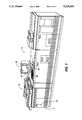
- FIG. 1is a view depicting an electronic printing system with the job supplement of the present invention allowing building of print jobs from diverse inputs or in response to special programming instructions;
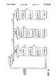
- FIG. 2is a block diagram depicting the major elements of the printing system shown in FIG. 1;
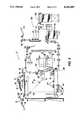
- FIG. 3is a plan view illustrating the principal mechanical components of the printing system shown in FIG. 1;
- FIGS. 5A, 5B, and 5Ccomprise a schematic block diagram showing the major parts of the system control section
- FIG. 6is a block diagram depicting the Operating System, with Printed Wiring Boards and shared line connections;
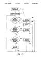
- FIGS. 7illustrates a flow chart of the bandwidth allocation in accordance with the present invention.
- FIGS. 1 and 2there is shown an exemplary laser based printing system 2 for processing print jobs in accordance with the teachings of the present invention.
- Printing system 2for purposes of explanation is divided into a scanner section 6, controller section 7, and printer section 8. While a specific printing system is shown and described, the present invention may be used with other types of printing systems such as ink jet, ionographic, etc.
- scanner section 6incorporates a transparent platen 20 on which the document 22 to be scanned is located.
- One or more linear arrays 24are supported for reciprocating scanning movement below platen 20.
- Lens 26 and mirrors 28, 29, 30cooperate to focus array 24 on a line-like segment of platen 20 and the document being scanned thereon.
- Array 24provides image signals or pixels representative of the image scanned which after suitable processing by processor 25, are output to controller section 7.
- Processor 25converts the analog image signals output by array 24 to digital and processes the image signals as required to enable system 2 to store and handle the image data in the form required to carry out the job programmed.
- Processor 25may provide enhancements and changes to the image signals such as filtering, thresholding, screening, cropping, etc.
- Documents 22 to be scannedmay be located on platen 20 for scanning by automatic document handler (ADF) 35 operable in either a Recirculating Document Handling (RDH) mode or a Semi-Automatic Document Handling (SADH) mode.
- a manual modeincluding a Book mode and a Computer Forms Feeder (CFF) mode are also provided, the latter to accommodate documents in the form of computer fanfold.
- document handler 35has a document tray 37 in which documents 22 are arranged in stacks or batches. The documents 22 in tray 37 are advanced by vacuum feed belt 40 and document feed rolls 41 and document feed belt 42 onto platen 20 where the document is scanned by array 24. Following scanning, the document is removed from platen 20 by belt 42 and returned to tray 37 by document feed rolls 44.
- a document entry slot 46provides access to the document feed belt 42 between tray 37 and platen 20 through which individual documents may be inserted manually for transport to platen 20. Feed rolls 49 behind slot 46 form a nip for engaging and feeding the document to feed belt 42 and onto platen 20. Following scanning, the document is removed from platen 20 and discharged into catch tray 48.
- document handler 35is pivoted upwardly to expose platen 20. This permits the document 22 to be manually placed on platen 20 following which array 24 is operated to scan the document. When scanning is completed, the document is removed to clear platen 20 for the next document.
- Book modethe book is manually positioned face down on platen 20 with the center line of the book aligned with positioning indicia (not shown) located along the border of platen 20. By programming the system, either one or both of the pages of the book open on the platen are scanned. The process is repeated for different pages of the book until all of the pages desired have been scanned following which the book is removed to clear platen 20.
- computer forms materialis fed through slot 46 and advanced by feed rolls 49 to document feed belt 42 which in turn advances a page of the fanfold material into position on platen 20.
- printer section 8comprises a laser type printer and for purposes of explanation is separated into a Raster Output Scanner (ROS) section 87, Print Module Section 95, Paper Supply section 107, and Finisher 120.
- ROS 95has a laser 91, the beam of which is split into two imaging beams 94.
- Each beam 94is modulated in accordance with the content of an image signal input by acousto-optic modulator 92 to provide dual imaging beams 94.
- Beams 94are scanned across a moving photoreceptor 98 of Print Module 95 by the mirrored facets of a rotating polygon 100 to expose two image lines on photoreceptor 98 with each scan and create the latent electrostatic images represented by the image signal input to modulator 92.
- Photoreceptor 98is uniformly charged by corotrons 102 at a charging station preparatory to exposure by imaging beams 94.
- the latent electrostatic imagesare developed by developer 104 and transferred at transfer station 106 to a print media 108 delivered by Paper Supply section 107.
- Media 108may comprise any of a variety of sheet sizes, types, and colors.
- the print mediais brought forward in timed registration with the developed image on photoreceptor 98 from either a main paper tray 110 or from auxiliary paper trays 112 or 114.
- the developed image transferred to the print media 108is permanently fixed or fused by fuser 116 and the resulting prints discharged to either output tray 118, or to finisher 120.
- Finisher 120includes a stitcher 122 for stitching or stapling the prints together to form books and a thermal binder 124 for adhesively binding the prints into books.
- controller section 7is, for explanation purposes, divided into an image input controller 50, User Interface (UI) 52, system controller 54, main memory 56, image manipulation section 58 and image output controller 60.
- UIUser Interface
- the scanned image data input from processor 25 of scanner section 6 to controller section 7is compressed by image compressor/processor 51 of image input controller 50 on PWB 70-3. As the image data passes through compressor/processor 51, it is segmented into slices N scanlines wide, each slice having a slice pointer.
- the compressed image data together with slice pointers and any related image descriptors providing image specific informationare placed in an image file.
- the image files, which represent different print jobs,are temporarily stored in system memory 61 which comprises a Random Access Memory or RAM pending transfer to main memory 56 where the data is held pending use.
- UI 52includes a combined operator controller/CRT display consisting of an interactive touchscreen 62, keyboard 64, and mouse 66.
- UI 52interfaces the operator with printing system 2, enabling the operator to program print jobs and other instructions, to obtain system operating information, instructions, programming information, diagnostic information, etc.
- Items displayed on touchscreen 62such as files and icons are actuated by either touching the displayed item on screen 62 with a finger or by using mouse 66 to point cursor 67 to the item selected and keying the mouse.
- Main memory 56has plural hard disks 90-1, 90-2, 90-3 for storing machine Operating System software, machine operating data, and the scanned image data currently being processed.
- main memory 56When the compressed image data in main memory 56 requires further processing, or is required for display on touchscreen 62 of UI 52, or is required by printer section 8, the data is accessed in main memory 56. Where further processing other than that provided by processor 25 is required, the data is transferred to image manipulation section 58 on PWB 70-6 where the additional processing steps such as collation, make ready, decomposition, etc. are carried out. Following processing, the data may be returned to main memory 56, sent to UI 52 for display on touchscreen 62, or sent to image output controller 60.
- Image data output to image output controller 60is decompressed and readied for printing by image generating processors 86 of PWBs 70-7, 70-8 (seen in FIG. 5A). Following this, the data is output by dispatch processors 88, 89 on PWB 70-9 to printer section 8. Image data sent to printer section 8 for printing is normally purged from memory 56 to make room for new image data.
- control section 7includes a plurality of Printed Wiring Boards (PWBs) 70, PWBs 70 being coupled with one another and with System Memory 61 by a pair of memory buses 72, 74.
- Memory controller 76couples System Memory 61 with buses 72, 74.
- PWBs 70include system processor PWB 70-1 having system processors 78; low speed I/O processor PWB 70-2 having UI communication controller 80 for transmitting data to and from UI 52; PWBs 70-3, 70-4, 70-5 having disk drive controller/processors 82 for transmitting data to and from disks 90-1, 90-2, 90-3 respectively of main memory 56 (image compressor/processor 51 for compressing the image data is on PWB 70-3); image manipulation PWB 70-6 with image manipulation processors of image manipulation section 58; image generation processor PWBs 70-7, 70-8 with image generation processors 86 for processing the image data for printing by printer section 8; dispatch processor PWB 70-9 having dispatch processors 88, 89 for controlling transmission of data to and from printer section 8; and boot control-arbitration-scheduler PWB 70-10.
- system control signalsare distributed via a plurality of printed wiring boards (PWBs). These include EDN core PWB 130, Marking Imaging core PWB 132, Paper Handling core PWB 134, and Finisher Binder core PWB 136 together with various Input/Output (I/O) PWBs 138.
- a system bus 140couples the core PWBs 130, 132, 134, 136 with each other and with controller section 7 while local buses 142 serve to couple the I/O PWBs 138 with each other and with their associated core PWB.
- the Operating System softwareis loaded from memory 56 to EDN core PWB 130 and from there to the remaining core PWBs 132, 134, 136 via bus 140, each core PWB 130, 132, 134, 136 having a boot ROM 147 for controlling downloading of Operating System software to the PWB, fault detection, etc.
- Boot ROMs 147also enable transmission of Operating System software and control data to and from PWBs 130, 132, 134, 136 via bus 140 and control data to and from I/O PWBs 138 via local buses 142. Additional ROM, RAM, and NVM memory types are resident at various locations within system 2.
- FIG. 7initially there is an allocation of bandwidth percentage for various priority resources of the machine as shown at 200.
- the scanner operationcould be allocated 12% of the available bandwidth, the printer allocated 44%, and non-volatile memory allocated 10% of the available bandwidth.
- Some operations or taskssuch as billing, diagnostics, and various management and background control procedures are non priority resources and have no allocation. Instead these non priority resources are left to obtain access when none of the priority resources such as the scanner, printer or non-volatile memory have access requirements or all the priority resources have exceeded the allocated percentage. It should be noted that this allocated percentage is normally given over a window in time, for example two seconds, after which the guaranteed times would be renewed for each of the priority resources.
- the guaranteed access percentagesare converted to actual time. This actual access time will, of course, depend upon the frequency of renewal of the access window.
- requests for bandwidth accessare monitored, as shown at 204, initially, the determination is made whether or not the requesting resource has guaranteed access or no guaranteed access to bandwidth. That is, whether or not it is a priority resource. If the answer is yes, there is guaranteed access to the particular resource requesting access. Then the request is processed at 206, and the history of usage or cumulated time of access updated at 208. It is assumed, of course, that the total time requested during the current request will not cause the requesting resource to exceed its allocation. This current access time is added to the total access time already accumulated by the requesting resource to be used as the reference for additional requests by the given resource during that particular access window.
- requests from non priority resourcesare monitored.
- the non priority resourcesare also monitored if no priority resource is requesting access.
- a decisionis made as shown at 210 whether or not there are requests from non priority resources with no guaranteed access. If there are, then the requests are processed as shown at 212. In other words, if none of the resources with guaranteed access have a current valid request for bandwidth access, then the request of the non-guaranteed resource can be honored and access granted. Finally, if there are no requests from a non-priority resource, then requests from priority resources are again monitored as illustrated at 214.
- decision block 214is relevant only if all the priority resources have already exceeded their allocated time within a given time window. Once a new time window is available, decision block 204 is the initial monitor of requests. If there are requests from priority resources still remaining within a given time window, then requests are processed as shown at 216. If there are no requests, then there is a period of waiting for requests as illustrated at 218. This period remains in effect until a new time window occurs. When the new time window occurs, the system returns to decision block 204 as discussed above.
Landscapes
- Engineering & Computer Science (AREA)
- Theoretical Computer Science (AREA)
- Human Computer Interaction (AREA)
- Physics & Mathematics (AREA)
- General Engineering & Computer Science (AREA)
- General Physics & Mathematics (AREA)
- Facsimiles In General (AREA)
Abstract
Description
Claims (12)
Priority Applications (1)
| Application Number | Priority Date | Filing Date | Title |
|---|---|---|---|
| US07/733,491US5218456A (en) | 1991-07-22 | 1991-07-22 | Disk bandwidth allocations to prioritize disk requests |
Applications Claiming Priority (1)
| Application Number | Priority Date | Filing Date | Title |
|---|---|---|---|
| US07/733,491US5218456A (en) | 1991-07-22 | 1991-07-22 | Disk bandwidth allocations to prioritize disk requests |
Publications (1)
| Publication Number | Publication Date |
|---|---|
| US5218456Atrue US5218456A (en) | 1993-06-08 |
Family
ID=24947826
Family Applications (1)
| Application Number | Title | Priority Date | Filing Date |
|---|---|---|---|
| US07/733,491Expired - LifetimeUS5218456A (en) | 1991-07-22 | 1991-07-22 | Disk bandwidth allocations to prioritize disk requests |
Country Status (1)
| Country | Link |
|---|---|
| US (1) | US5218456A (en) |
Cited By (17)
| Publication number | Priority date | Publication date | Assignee | Title |
|---|---|---|---|---|
| US5495339A (en)* | 1991-08-19 | 1996-02-27 | Xerox Corporation | Scheduling multiple disk requests and writing data buffers to disk |
| US5506660A (en)* | 1994-09-06 | 1996-04-09 | Xerox Corporation | Multi-pitch paper and image handling on seamed belt |
| US6016503A (en)* | 1997-08-29 | 2000-01-18 | International Business Machines Corporation | Methods, systems and computer program products for preemptive avoidance of constraints for shared resources |
| WO2000025220A1 (en)* | 1998-10-27 | 2000-05-04 | Fujitsu Network Communications, Inc. | Network to network priority frame dequeuing |
| US6289383B1 (en)* | 1998-11-30 | 2001-09-11 | Hewlett-Packard Company | System and method for managing data retrieval bandwidth |
| US6480296B1 (en)* | 1998-01-12 | 2002-11-12 | Canon Kabushiki Kaisha | Image processing apparatus and memory access method therefor |
| US20030074519A1 (en)* | 2001-10-12 | 2003-04-17 | Wolf-Dietrich Weber | Method and apparatus for scheduling of requests to dynamic random access memory device |
| WO2003034242A1 (en)* | 2001-10-12 | 2003-04-24 | Sonics, Inc. | Method and apparatus for scheduling a resource to meet quality-of-service restrictions |
| US6578117B2 (en) | 2001-10-12 | 2003-06-10 | Sonics, Inc. | Method and apparatus for scheduling requests using ordered stages of scheduling criteria |
| US20050038940A1 (en)* | 2000-09-28 | 2005-02-17 | Hitachi, Ltd. | Storage control apparatus |
| US20050096970A1 (en)* | 2003-10-31 | 2005-05-05 | Wolf-Dietrich Weber | Method and apparatus for establishing a quality of service model |
| US7194561B2 (en) | 2001-10-12 | 2007-03-20 | Sonics, Inc. | Method and apparatus for scheduling requests to a resource using a configurable threshold |
| EP1895397A1 (en)* | 2006-09-01 | 2008-03-05 | Hitachi, Ltd. | Storage system and data input/output control method |
| US20080120085A1 (en)* | 2006-11-20 | 2008-05-22 | Herve Jacques Alexanian | Transaction co-validation across abstraction layers |
| US20090217273A1 (en)* | 2008-02-26 | 2009-08-27 | Microsoft Corporation | Controlling interference in shared memory systems using parallelism-aware batch scheduling |
| US20100211935A1 (en)* | 2003-10-31 | 2010-08-19 | Sonics, Inc. | Method and apparatus for establishing a quality of service model |
| US9087036B1 (en) | 2004-08-12 | 2015-07-21 | Sonics, Inc. | Methods and apparatuses for time annotated transaction level modeling |
Citations (7)
| Publication number | Priority date | Publication date | Assignee | Title |
|---|---|---|---|---|
| US4332463A (en)* | 1980-06-20 | 1982-06-01 | Eastman Kodak Company | Non-synchronous operation of an electronic copier |
| US4564864A (en)* | 1981-11-04 | 1986-01-14 | Canon Kabushiki Kaisha | Image forming apparatus |
| US4719516A (en)* | 1981-12-25 | 1988-01-12 | Canon Kabushiki Kaisha | Image processing apparatus |
| US4748513A (en)* | 1985-01-31 | 1988-05-31 | Canon Kabushiki Kaisha | Image processing system |
| US5021892A (en)* | 1986-09-30 | 1991-06-04 | Sharp Kabushiki Kaisha | Image processing device of multifunctional type |
| US5025483A (en)* | 1987-12-18 | 1991-06-18 | International Business Machines Corporation | System for scanning documents without loss of image data |
| US5087979A (en)* | 1990-12-24 | 1992-02-11 | Eastman Kodak Company | Digital copier or printer with collating buffer memory of limited page capacity and with alternative printing modes when required memory exceeds capacity |
- 1991
- 1991-07-22USUS07/733,491patent/US5218456A/ennot_activeExpired - Lifetime
Patent Citations (7)
| Publication number | Priority date | Publication date | Assignee | Title |
|---|---|---|---|---|
| US4332463A (en)* | 1980-06-20 | 1982-06-01 | Eastman Kodak Company | Non-synchronous operation of an electronic copier |
| US4564864A (en)* | 1981-11-04 | 1986-01-14 | Canon Kabushiki Kaisha | Image forming apparatus |
| US4719516A (en)* | 1981-12-25 | 1988-01-12 | Canon Kabushiki Kaisha | Image processing apparatus |
| US4748513A (en)* | 1985-01-31 | 1988-05-31 | Canon Kabushiki Kaisha | Image processing system |
| US5021892A (en)* | 1986-09-30 | 1991-06-04 | Sharp Kabushiki Kaisha | Image processing device of multifunctional type |
| US5025483A (en)* | 1987-12-18 | 1991-06-18 | International Business Machines Corporation | System for scanning documents without loss of image data |
| US5087979A (en)* | 1990-12-24 | 1992-02-11 | Eastman Kodak Company | Digital copier or printer with collating buffer memory of limited page capacity and with alternative printing modes when required memory exceeds capacity |
Cited By (39)
| Publication number | Priority date | Publication date | Assignee | Title |
|---|---|---|---|---|
| US5495339A (en)* | 1991-08-19 | 1996-02-27 | Xerox Corporation | Scheduling multiple disk requests and writing data buffers to disk |
| US5506660A (en)* | 1994-09-06 | 1996-04-09 | Xerox Corporation | Multi-pitch paper and image handling on seamed belt |
| US6016503A (en)* | 1997-08-29 | 2000-01-18 | International Business Machines Corporation | Methods, systems and computer program products for preemptive avoidance of constraints for shared resources |
| US6480296B1 (en)* | 1998-01-12 | 2002-11-12 | Canon Kabushiki Kaisha | Image processing apparatus and memory access method therefor |
| US6661802B1 (en) | 1998-10-27 | 2003-12-09 | Fujitsu Network Communications, Inc. | Congestion management |
| WO2000025220A1 (en)* | 1998-10-27 | 2000-05-04 | Fujitsu Network Communications, Inc. | Network to network priority frame dequeuing |
| US6169748B1 (en) | 1998-10-27 | 2001-01-02 | Fujitsu Network Communications, Inc. | Frame based quality of service |
| US6233240B1 (en) | 1998-10-27 | 2001-05-15 | Fujitsu Network Communications, Inc. | Event based rate policing with a jumping window |
| US6256315B1 (en) | 1998-10-27 | 2001-07-03 | Fujitsu Network Communications, Inc. | Network to network priority frame dequeuing |
| US6289383B1 (en)* | 1998-11-30 | 2001-09-11 | Hewlett-Packard Company | System and method for managing data retrieval bandwidth |
| US6332140B1 (en)* | 1998-11-30 | 2001-12-18 | Hewlett-Packard Company | System and method for managing data retrieval bandwidth |
| US7478231B2 (en) | 2000-09-28 | 2009-01-13 | Hitachi, Ltd. | Storage control apparatus |
| US20060248237A1 (en)* | 2000-09-28 | 2006-11-02 | Hitachi, Ltd. | Storage control apparatus |
| US7181607B2 (en)* | 2000-09-28 | 2007-02-20 | Hitachi, Ltd. | Storage control apparatus |
| EP1193604A3 (en)* | 2000-09-28 | 2006-01-25 | Hitachi, Ltd. | Storage control apparatus |
| US20050038940A1 (en)* | 2000-09-28 | 2005-02-17 | Hitachi, Ltd. | Storage control apparatus |
| US7191273B2 (en) | 2001-10-12 | 2007-03-13 | Sonics, Inc. | Method and apparatus for scheduling a resource to meet quality-of-service restrictions |
| US6961834B2 (en) | 2001-10-12 | 2005-11-01 | Sonics, Inc. | Method and apparatus for scheduling of requests to dynamic random access memory device |
| US6804757B2 (en) | 2001-10-12 | 2004-10-12 | Sonics, Inc. | Method and apparatus for scheduling requests using ordered stages of scheduling criteria |
| WO2003034242A1 (en)* | 2001-10-12 | 2003-04-24 | Sonics, Inc. | Method and apparatus for scheduling a resource to meet quality-of-service restrictions |
| US6804738B2 (en) | 2001-10-12 | 2004-10-12 | Sonics, Inc. | Method and apparatus for scheduling a resource to meet quality-of-service restrictions |
| US7194561B2 (en) | 2001-10-12 | 2007-03-20 | Sonics, Inc. | Method and apparatus for scheduling requests to a resource using a configurable threshold |
| US6578117B2 (en) | 2001-10-12 | 2003-06-10 | Sonics, Inc. | Method and apparatus for scheduling requests using ordered stages of scheduling criteria |
| US20030074519A1 (en)* | 2001-10-12 | 2003-04-17 | Wolf-Dietrich Weber | Method and apparatus for scheduling of requests to dynamic random access memory device |
| US20050096970A1 (en)* | 2003-10-31 | 2005-05-05 | Wolf-Dietrich Weber | Method and apparatus for establishing a quality of service model |
| US7665069B2 (en) | 2003-10-31 | 2010-02-16 | Sonics, Inc. | Method and apparatus for establishing a quality of service model |
| US8504992B2 (en) | 2003-10-31 | 2013-08-06 | Sonics, Inc. | Method and apparatus for establishing a quality of service model |
| US20100211935A1 (en)* | 2003-10-31 | 2010-08-19 | Sonics, Inc. | Method and apparatus for establishing a quality of service model |
| US9087036B1 (en) | 2004-08-12 | 2015-07-21 | Sonics, Inc. | Methods and apparatuses for time annotated transaction level modeling |
| EP1895397A1 (en)* | 2006-09-01 | 2008-03-05 | Hitachi, Ltd. | Storage system and data input/output control method |
| US20090271535A1 (en)* | 2006-09-01 | 2009-10-29 | Yasuhiko Yamaguchi | Storage system and data input/output control method |
| US8051219B2 (en) | 2006-09-01 | 2011-11-01 | Hitachi, Ltd. | Storage system with performance limit detection unit and processing percentage determination unit for ensuring priority data performance |
| US20080126645A1 (en)* | 2006-09-01 | 2008-05-29 | Yasuhiko Yamaguchi | Storage system and data input/output control method |
| US8868397B2 (en) | 2006-11-20 | 2014-10-21 | Sonics, Inc. | Transaction co-validation across abstraction layers |
| US20080120085A1 (en)* | 2006-11-20 | 2008-05-22 | Herve Jacques Alexanian | Transaction co-validation across abstraction layers |
| US20090216962A1 (en)* | 2008-02-26 | 2009-08-27 | Microsoft Corporation | Prioritization of multiple concurrent threads for scheduling requests to shared memory |
| US20090217273A1 (en)* | 2008-02-26 | 2009-08-27 | Microsoft Corporation | Controlling interference in shared memory systems using parallelism-aware batch scheduling |
| US8180975B2 (en)* | 2008-02-26 | 2012-05-15 | Microsoft Corporation | Controlling interference in shared memory systems using parallelism-aware batch scheduling |
| US8271741B2 (en)* | 2008-02-26 | 2012-09-18 | Microsoft Corporation | Prioritization of multiple concurrent threads for scheduling requests to shared memory |
Similar Documents
| Publication | Publication Date | Title |
|---|---|---|
| JP3732235B2 (en) | Electronic duplicator | |
| US5170340A (en) | System state controller for electronic image processing systems | |
| US5175679A (en) | Control for electronic image processing systems | |
| US5218456A (en) | Disk bandwidth allocations to prioritize disk requests | |
| US5363175A (en) | Distributed job scheduling with modular components | |
| US5081595A (en) | Paper supply tray status in electronic printers | |
| US5206735A (en) | Job interrupt for electronic copying/printing machines | |
| US5191429A (en) | Electronic printing system for printing multiple images with determination of the maximum number of reduced size images to be optimally printed on a sheet of detected size without interference | |
| EP0478340A2 (en) | Electronic reprographic printing system | |
| US5697040A (en) | Print job intermixing within marking machine | |
| US5305056A (en) | Method of controlling diagnostics in a printing system | |
| US5210622A (en) | Automatic variable image shift for precut tabs | |
| US5533172A (en) | Method of printing a print job with a print file | |
| CA2138070C (en) | Method of printing a print job with a print file | |
| EP0469865A2 (en) | Electronic printing | |
| US5495339A (en) | Scheduling multiple disk requests and writing data buffers to disk | |
| US5212566A (en) | Synchronization of ess/iit when scanning complex documents | |
| EP0465179B2 (en) | Electronic copying/printing machines | |
| US5200960A (en) | Streaming tape diagnostic |
Legal Events
| Date | Code | Title | Description |
|---|---|---|---|
| AS | Assignment | Owner name:XEROX CORPORATION, CONNECTICUT Free format text:ASSIGNMENT OF ASSIGNORS INTEREST.;ASSIGNORS:STEGBAUER, RANDALL J.;FEDERICO, ANTHONY M.;IPPOLITO, RONALD A.;AND OTHERS;REEL/FRAME:005781/0816;SIGNING DATES FROM 19910711 TO 19910716 | |
| STCF | Information on status: patent grant | Free format text:PATENTED CASE | |
| FPAY | Fee payment | Year of fee payment:4 | |
| FPAY | Fee payment | Year of fee payment:8 | |
| AS | Assignment | Owner name:BANK ONE, NA, AS ADMINISTRATIVE AGENT, ILLINOIS Free format text:SECURITY INTEREST;ASSIGNOR:XEROX CORPORATION;REEL/FRAME:013153/0001 Effective date:20020621 | |
| AS | Assignment | Owner name:JPMORGAN CHASE BANK, AS COLLATERAL AGENT, TEXAS Free format text:SECURITY AGREEMENT;ASSIGNOR:XEROX CORPORATION;REEL/FRAME:015134/0476 Effective date:20030625 Owner name:JPMORGAN CHASE BANK, AS COLLATERAL AGENT,TEXAS Free format text:SECURITY AGREEMENT;ASSIGNOR:XEROX CORPORATION;REEL/FRAME:015134/0476 Effective date:20030625 | |
| FPAY | Fee payment | Year of fee payment:12 | |
| AS | Assignment | Owner name:XEROX CORPORATION, CONNECTICUT Free format text:RELEASE BY SECURED PARTY;ASSIGNOR:JPMORGAN CHASE BANK, N.A. AS SUCCESSOR-IN-INTEREST ADMINISTRATIVE AGENT AND COLLATERAL AGENT TO JPMORGAN CHASE BANK;REEL/FRAME:066728/0193 Effective date:20220822 |