US5217487A - Back therapy system - Google Patents
Back therapy systemDownload PDFInfo
- Publication number
- US5217487A US5217487AUS07/736,009US73600991AUS5217487AUS 5217487 AUS5217487 AUS 5217487AUS 73600991 AUS73600991 AUS 73600991AUS 5217487 AUS5217487 AUS 5217487A
- Authority
- US
- United States
- Prior art keywords
- person
- pad member
- segment
- supporting means
- pad
- Prior art date
- Legal status (The legal status is an assumption and is not a legal conclusion. Google has not performed a legal analysis and makes no representation as to the accuracy of the status listed.)
- Expired - Fee Related
Links
- 238000002560therapeutic procedureMethods0.000titleclaimsabstractdescription33
- 210000004197pelvisAnatomy0.000claimsabstractdescription24
- 238000009208inversion therapyMethods0.000claimsdescription14
- 230000006641stabilisationEffects0.000claimsdescription11
- 238000011105stabilizationMethods0.000claimsdescription11
- 230000000087stabilizing effectEffects0.000claimsdescription7
- 210000001217buttockAnatomy0.000description5
- 210000001624hipAnatomy0.000description4
- 238000002955isolationMethods0.000description4
- 230000033001locomotionEffects0.000description4
- 230000000750progressive effectEffects0.000description4
- 239000011800void materialSubstances0.000description4
- 238000013459approachMethods0.000description3
- 238000011282treatmentMethods0.000description3
- 210000003815abdominal wallAnatomy0.000description2
- 238000005452bendingMethods0.000description2
- 208000037516chromosome inversion diseaseDiseases0.000description2
- 210000003127kneeAnatomy0.000description2
- 210000002414legAnatomy0.000description2
- 210000004705lumbosacral regionAnatomy0.000description2
- 230000000276sedentary effectEffects0.000description2
- 230000007704transitionEffects0.000description2
- 210000000689upper legAnatomy0.000description2
- 206010023204Joint dislocationDiseases0.000description1
- 229920005830Polyurethane FoamPolymers0.000description1
- 229910000831SteelInorganic materials0.000description1
- 230000003187abdominal effectEffects0.000description1
- 210000003489abdominal muscleAnatomy0.000description1
- 230000004913activationEffects0.000description1
- 230000037396body weightEffects0.000description1
- 244000309466calfSpecies0.000description1
- 210000005069earsAnatomy0.000description1
- 230000000694effectsEffects0.000description1
- 229920001971elastomerPolymers0.000description1
- 230000004807localizationEffects0.000description1
- 210000003205muscleAnatomy0.000description1
- 230000007935neutral effectEffects0.000description1
- 239000011496polyurethane foamSubstances0.000description1
- 230000002040relaxant effectEffects0.000description1
- 230000029058respiratory gaseous exchangeEffects0.000description1
- 239000010959steelSubstances0.000description1
- 210000000115thoracic cavityAnatomy0.000description1
Images


Classifications
- A—HUMAN NECESSITIES
- A61—MEDICAL OR VETERINARY SCIENCE; HYGIENE
- A61H—PHYSICAL THERAPY APPARATUS, e.g. DEVICES FOR LOCATING OR STIMULATING REFLEX POINTS IN THE BODY; ARTIFICIAL RESPIRATION; MASSAGE; BATHING DEVICES FOR SPECIAL THERAPEUTIC OR HYGIENIC PURPOSES OR SPECIFIC PARTS OF THE BODY
- A61H1/00—Apparatus for passive exercising; Vibrating apparatus; Chiropractic devices, e.g. body impacting devices, external devices for briefly extending or aligning unbroken bones
- A61H1/02—Stretching or bending or torsioning apparatus for exercising
- A61H1/0292—Stretching or bending or torsioning apparatus for exercising for the spinal column
- Y—GENERAL TAGGING OF NEW TECHNOLOGICAL DEVELOPMENTS; GENERAL TAGGING OF CROSS-SECTIONAL TECHNOLOGIES SPANNING OVER SEVERAL SECTIONS OF THE IPC; TECHNICAL SUBJECTS COVERED BY FORMER USPC CROSS-REFERENCE ART COLLECTIONS [XRACs] AND DIGESTS
- Y10—TECHNICAL SUBJECTS COVERED BY FORMER USPC
- Y10S—TECHNICAL SUBJECTS COVERED BY FORMER USPC CROSS-REFERENCE ART COLLECTIONS [XRACs] AND DIGESTS
- Y10S482/00—Exercise devices
- Y10S482/907—Stretching
Definitions
- the present inventionrelates generally to back therapy apparatus, and more particularly, to a multi-purpose back therapy apparatus designed to facilitate flexion distraction maneuvers, McKenzie extension exercises, Williams flexion exercises, and inversion therapy.
- flexion distraction maneuversare used to stretch out the posterior compartments of the lumbar spine and its myofascial components in the coronal, sagittal, and transverse planes of motion.
- McKenzie extension exercisesare recommended for patients with sedentary lifestyles and for persons involved in excessive forward bending and lifting at the thoraco-lumbar junction.
- Williams flexion exercisesare prescribed for patients requiring flexion distraction maneuvers to strengthen the abdominal wall.
- inversion therapyemploys the weight of the upper body for safer application of passive traction without stress to any other joints.
- the present inventionprovides a back therapy apparatus that facilitates all four such protocols.
- the present inventionprovides an apparatus of a type on which a person receives back therapy.
- the apparatusincludes a rigid frame designed to rest upon a floor surface; a supporting means, pivotally mounted to the frame above the floor surface, for supporting the person's pelvis and upper body; a pelvic stabilization means, secured relative to the supporting means, for stabilizing the person's pelvis relative to the supporting means; and a support locking means, operatively connected to the supporting means, for locking the supporting means in any one of a plurality of positions.
- the supporting meanspivots from a mounting position suitable for mounting by the person; to a first operable position suitable for flexion distraction maneuvers; to a second operable position suitable for McKenzie extension exercises; to a third operable position suitable for Williams flexion exercises; and to a fourth operable position suitable for inversion therapy.
- the frameincludes (1) a base member having a front end and a rear end and designed to rest upon a floor surface; (2) an intermediate support member extending up from the floor surface and to which the supporting means is pivotally mounted; (3) a first elevation foot support extending up from the floor surface proximate the rear end; and (4) a second elevation foot support extending up from the floor surface proximate the rear end.
- the supporting meansis also rotatably mounted to the frame, and thus, is capable of rotating out of its plane of pivoting. As a result, the supporting means is accessible for mounting by persons who are otherwise unable to mount the supporting means due to handicap or excessive size, which prevents access between the supporting means and the foot supports.
- the supporting meansincludes a pad member having a contoured, person engaging surface characterized by a substantially rounded first segment joined to a substantially flat second segment joined to a substantially flat third segment.
- the first segmentfaces away from the second segment, and the second segment faces away from the third segment.
- the surfaceis symmetrical about its longitudinal axis, and the surface is interrupted by a longitudinally oriented void. When in the mounting position, the surface faces substantially toward the rear end, and the first segment is between the intermediate support member and the rear end.
- the pelvic stabilization meansincludes a strap member secured to the pad member behind the first segment.
- the first elevation foot support and the supporting meansare spatially positioned relative to one another such that when the person's pelvis is stabilized relative to the supporting means and he supporting means is pivoted to and locked in the second operable position, the first elevation foot support provides support for the feet of the person performing McKenzie extension exercises.
- the second elevation foot support and the supporting meansare spatially positioned relative to one another such that when the pelvis of the person is stabilized relative to the supporting means and the supporting means is pivoted to and locked in the third operable position, the second elevation foot support provides support for the feet of the person performing Williams flexion exercises. Also, when the supporting means is pivoted to and locked in the fourth operable position, the second elevation foot support provides support for the feet of the person undergoing inversion therapy.
- the apparatusmay additionally include (1) segmental isolation means, secured relative to the supporting means, for isolating a particular segment of the person's back by stabilizing that portion of the person's back immediately below the particular segment to be isolated; and (2) an isotonic exercise device, secured to the frame proximate the front end, and designed to be operated by the person pivoted to and locked in the second operable position.
- the present inventionprovides several advantages.
- the present inventionprovides a single, relatively compact and inexpensive piece of equipment that is suitable for four different back therapy protocols: flexion distraction maneuvers; McKenzie extension exercises; Williams flexion exercises; and inversion therapy.
- the present inventionalso offers flexibility with respect to patients' particular physical status and therapy needs. Persons of various sizes and having various needs can be comfortably and effectively positioned on the pad member, which can then be maneuvered to a desired position. Once an ideal position is achieved, the position is locked in place by simply turning a knob, at which point the therapist is completely free to administer therapy to the patient.
- the present inventionalso provides a safer and more effective therapy system. By unloading the spine while stretching and relaxing the back, specific muscle groups can be more readily isolated for more effective therapy. Also, the use of the pelvic stabilization belt reduces stress on inflamed joints, allowing inversion therapy at a variety of angles to provide passive, progressive resistance. The availability of a segmental isolation strap and an isotonic exercise device provide the therapist with additional options for more aggressive approaches to treatment.
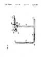
- FIG. 1is a perspective view of a preferred embodiment of the back therapy apparatus of the present invention
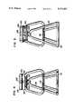
- FIG. 2is a right side view of the preferred embodiment of the back therapy apparatus of FIG. 1;
- FIG. 3is a left side view of the preferred embodiment of the back therapy apparatus of FIG. 1;
- FIG. 4is a front view of the preferred embodiment of the back therapy apparatus of FIG. 1;
- FIG. 5is a rear view of the preferred embodiment of the back therapy apparatus of FIG. 1;
- FIG. 6is a bottom view of the preferred embodiment of the back therapy apparatus of FIG. 1;
- FIG. 7is a top view of the preferred embodiment of the back therapy apparatus of FIG. 1;
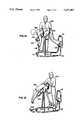
- FIG. 8is a perspective view of the preferred embodiment of the back therapy apparatus of FIG. 1 in a first mounting position
- FIG. 9is a perspective view of the preferred embodiment of the back therapy apparatus of FIG. 1 in a second mounting position
- FIG. 10is a perspective view of the preferred embodiment of the back therapy apparatus of FIG. 1 in a first operable configuration suitable for flexion distraction maneuvers, having been mounted by a patient who is attended by a therapist;
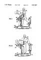
- FIG. 11is a perspective view of the preferred embodiment of the back therapy apparatus of FIG. 1 in a second operable configuration suitable for McKenzie extension exercises, having been mounted by a patient who is attended by a therapist;
- FIG. 12is a perspective view of the preferred embodiment of the back therapy apparatus of FIG. 1 in a third operable position suitable for Williams flexion exercises, having been mounted by a patient who is attended by a therapist;
- FIG. 13is a perspective view of the preferred embodiment of the back therapy apparatus of FIG. 1 in a fourth operable position suitable for inversion therapy, having been mounted by a patient who is attended by a therapist;
- FIG. 14is a perspective view of the preferred embodiment of the back therapy apparatus of FIG. 11 in the second operable position suitable for McKenzie extension exercises, having been mounted by a patient who is attended by a therapist, and with the patient performing isotonic exercises.
- the apparatus 100includes a rigid frame 101; a supporting means 102 for supporting a person at the pelvis and upper body; a pelvic stabilization means 103 for stabilizing the person's pelvis relative to the supporting means 102; and a support locking means 104 for locking the supporting means 102 in any one of a plurality of positions.
- the frame 101is designed to rest upon a floor surface 109, and the supporting means 102 is pivotally and rotatably mounted to the frame 101 above the floor surface 109.
- conventional pivoting means 105 and rotating means 106allow the supporting means 102 to pivot and rotate, respectively, relative to the frame 101.
- the pelvis stabilization means 103is secured relative to the supporting means 102, and the support locking means 104 is operatively connected to the supporting means 102.
- the supporting means 102pivots among a plurality of positions, including a mounting position suitable for mounting by the person, as shown in FIGS. 8 and 9; a first operable position suitable for flexion distraction maneuvers, as shown in FIG. 10; a second operable position suitable for McKenzie extension exercises, as shown in FIG. 11; a third operable position suitable for Williams flexion exercises, as shown in FIG. 12; and a fourth operable position suitable for inversion therapy, as shown in FIG. 13.
- Rotation of knob 140which forms a part of the support locking means 104, in a first direction "locks" the supporting means 102 in any one of the plurality of positions, and rotation of knob 140 in the opposite direction releases the supporting means 102.
- the frame 101is constructed of two inch steel tubing.
- the frame 101includes (1) a base member 111 having a front end 112 and a rear end 113 and designed to rest upon the floor surface 109; (2) an intermediate support member 114 extending up from the floor surface 109 and to which the supporting means 102 is pivotally and rotatably mounted; (3) a first elevation foot support 115 extending up from the floor surface 109 proximate the rear end 113; and (4) a second elevation foot support 116 extending up from the floor surface 109 proximate the rear end 113.
- the base member 111is substantially planar, such that when the apparatus 100 is an operable orientation, the base member 111 defines a substantially horizontal plane parallel to the floor surface 109.
- the intermediate support member 114defines a plane that is substantially perpendicular to the plane defined by the base member 116.
- the foot supports 115 and 116define a plane that is substantially perpendicular to the plane defined by the base member 111, and parallel to that of the intermediate support member 114.
- the intermediate support member 114may be said to be an intermediate upright member, and the structure defining the foot supports 115 and 116 may be said to be a rear upright member.
- the plane of pivoting defined by the pivoting of the pad member 120is perpendicular to all three of the above-mentioned planes.
- the first elevation foot support 115 and the supporting means 102are spatially positioned relative to one another such that when the person's pelvis is stabilized relative to the supporting means 102 and the supporting means 102 is pivoted to and locked in the second operable position, the first elevation foot support 115 provides support for the feet of the person 190 performing McKenzie extension exercises, as shown in FIG. 11.
- the second elevation foot support 116 and the supporting means 102are spatially positioned relative to one another such that when the person's pelvis is stabilized relative to the supporting means 102 and the supporting means 102 is pivoted to and locked in the third operable position, the second elevation foot support 116 provides support for the feet of the person performing Williams flexion exercises, as shown in FIG. 12.
- the second elevation foot support 116 and the supporting means 102are spatially positioned relative to one another such that when the person's pelvis is stabilized relative to the supporting means 102 and the supporting means 102 is pivoted to and locked in the fourth operable position, the second elevation foot support 116 provides support for the feet of the person receiving inversion therapy, as shown in FIG. 13.
- the foot supports 115 and 116also provide a convenient support for stretching exercises prior to mounting the supporting means 102.
- the supporting means 102includes a pad member 120 having a contoured, person engaging surface 129 characterized by a substantially rounded first segment 121 joined to a substantially flat second segment 122 joined to a substantially flat third segment 123.
- the surface 129is defined by the outer surface of a self-skinning, high density polyurethane foam, which is mounted to a more rigid substructure.
- the first segment 121faces away from the second segment 122, and the second segment 122 faces away from the third segment 123.
- the contour 129 of the pad member 120is designed to provide comfort and necessary support for the patient's pelvis and upper body throughout the plurality of positions and the ranges of patient movement in each position.
- the surface 129is symmetrical about its longitudinal axis, as shown in FIG. 7, and the surface 129 is interrupted by a longitudinally oriented void 125.
- the void 125provides breathing space for the patient when facing the pad member 120 during flexion distraction maneuvers, McKenzie extension exercises, and inversion therapy, and the void 125 provides clearance for the spine of the patient when lying back against the pad member 120 during Williams flexion exercises.
- the surface 129faces substantially toward the rear end 113, and the first segment 121 is between the intermediate support member 114 and the rear end 113.
- the patientapproaches the pad member 120 from the rear end side and presses up against the first segment 121 and leans over the second segment 122 and the third segment 123.
- a strap member 130which is secured to the pad member 120 behind the first segment 121, is fastened about the patient's buttocks or waist (depending on the specific protocol) to stabilize the person's pelvis relative to the pad member 120. Because the patient is standing behind the pivot point 150 (shown in FIGS.
- the patientis lifted from the floor surface 109 as the pad member 120 is pivoted forward.
- the rounded configuration of the first segment 121is well suited to engage the base of the patient's torso and roll the patient off the floor surface and about the pivot point 150.
- the support locking means 104is engaged to releasably retain the pad member 120 in the desired position. At this point the patient is in the desired position, and the therapist's hands are free to administer therapy and/or make any necessary adjustments.
- the supporting means 102is also rotatably mounted to the frame 101, such that the supporting means 102 is capable of rotating out of its plane of pivoting about an axis perpendicular to the floor surface 109.
- the pad member 120may be rotated to a more accessible orientation, as shown in FIG. 9.
- the apparatus 100When the supporting means 102 is locked in the first operable position, the apparatus 100 is suitable for flexion distraction maneuvers, as shown in FIG. 10.
- flexion distraction maneuversare used to stretch out the posterior compartments of the lumbar spine and its myofascial components in the coronal, sagittal, and transverse planes of motion.
- the patient 190faces the pad member 120 and leans up against it, and the patient's pelvis is stabilized by the fastening of the strap member 130 about the patient's buttocks.
- the pad member 120Upon pivoting of the pad member 120 to the first position, the person's legs hang off the pad member 120, extended at the knee and flexed at the hip.
- the therapist 199then stands to the rear of the patient 190 with one hand on the patient's lumbar area and the opposite thigh and knee at the patient posterior thigh and calf area.
- the therapist 199then gently applies superficial traction towards the patient's head with a hand on the lumbar while the patient attempts to lift his legs into extension at the hip against the therapist's resisting force.
- the lumbar extensorwill attempt to contract against the therapist's manual traction in the direction of the head. Repetition of this thoraco-lumbar transition, one segment at a time, effectively stretches out the posterior vertebral and sacro-iliac compartments and is very effective in acute-care management.
- the apparatus 100When the supporting means 102 is locked in the second operable position, the apparatus 100 is suitable for McKenzie extension exercises, as shown in FIG. 11. Those skilled in the art will recognize that McKenzie extension exercises are useful for patients with sedentary lifestyles and persons involved in excessive forward bending and lifting at the thoraco-lumbar injunction.
- the patient 190faces the pad member 120 and leans up against it, and the patient's pelvis is stabilized by the fastening of the strap member 130 about the patient's buttocks.
- the patient's feetmay rest on either foot support 115 or 116, depending on the flexibility of the hamstrings.
- the patient 190is then typically instructed to extend straight upwards, hands behind back, chin tucked or in a neutral position.
- progressive resistanceis provided to flexion subluxation of the lower thoracic segments on the extended upper lumbar segments.
- the apparatus 100may additionally include (1) segmental isolation means 107, secured relative to the supporting means 102, for isolating a particular segment of the person's back by stabilizing that portion of the person's back immediately below the particular segment to be isolated; and (2) an isotonic exercise device 108, secured to the frame 101 proximate the front end 112, and designed to be operated by the person pivoted to and locked in the second operable position.
- segmental isolation means 107secured relative to the supporting means 102, for isolating a particular segment of the person's back by stabilizing that portion of the person's back immediately below the particular segment to be isolated
- an isotonic exercise device 108secured to the frame 101 proximate the front end 112, and designed to be operated by the person pivoted to and locked in the second operable position.
- Appropriate localization of the strap member that provides the segmental isolation means 107 below the involved segmentpermits more accurate mobilization of the involved segment in the sagittal plane of extension.
- the apparatus 100When the supporting means 102 is locked in the third operable position, the apparatus 100 is suitable for Williams flexion exercises, as shown in FIG. 12. Those skilled in the art will recognize that Williams flexion exercises are typically prescribed for patients requiring the flexion distraction maneuvers to strengthen the abdominal wall. Contrary to the other treatment protocols, the patient 190 approaches the pad member 120 with the buttocks placed against the pad member 120. The pelvic locking strap member 130 is then secured about the patient's waist to prevent pelvic rotation and to isolate abdominal muscle activation. Upon pivoting of the pad member 120 to the third position, the patient 190 can place one foot on the lower foot support 115 to move into the desired exercise position.
- the patientlies back onto the pad member 120, places the feet on the foot supports 115 and 116, and places hands by the ears, and then gently raises and lowers the shoulders off and back to the support pad 120 to and from the point of flexion desired.
- the support pad 120should be angled to support the thoraco-lumbar transition and allow for slight extension of the upper torso, thereby providing a prestretch of the abdominal at the onset and completion of the exercise. Progressive resistance is afforded by tipping the body support pad into progressive inversion, thereby increasing the distribution of the body weight superiorly.
- inversion therapyemploys the weight of the upper body for safer application of passive traction without stress to any other joints.
- the patient 190faces the pad member 120 and leans up against it, an the patient's pelvis is stabilized by the fastening of the strap member 130 about the patient's buttocks.
- the pad to the fourth positionconstituting the desired angle of inversion
- the patient's feetmay be placed over the upper-rear support bar if necessary. At this point the therapist may provide additional traction assistance as needed.
Landscapes
- Health & Medical Sciences (AREA)
- Engineering & Computer Science (AREA)
- Biomedical Technology (AREA)
- Neurology (AREA)
- Orthopedic Medicine & Surgery (AREA)
- Epidemiology (AREA)
- Pain & Pain Management (AREA)
- Physical Education & Sports Medicine (AREA)
- Rehabilitation Therapy (AREA)
- Life Sciences & Earth Sciences (AREA)
- Animal Behavior & Ethology (AREA)
- General Health & Medical Sciences (AREA)
- Public Health (AREA)
- Veterinary Medicine (AREA)
- Orthopedics, Nursing, And Contraception (AREA)
Abstract
Description
Claims (8)
Priority Applications (1)
| Application Number | Priority Date | Filing Date | Title |
|---|---|---|---|
| US07/736,009US5217487A (en) | 1991-07-25 | 1991-07-25 | Back therapy system |
Applications Claiming Priority (1)
| Application Number | Priority Date | Filing Date | Title |
|---|---|---|---|
| US07/736,009US5217487A (en) | 1991-07-25 | 1991-07-25 | Back therapy system |
Publications (1)
| Publication Number | Publication Date |
|---|---|
| US5217487Atrue US5217487A (en) | 1993-06-08 |
Family
ID=24958124
Family Applications (1)
| Application Number | Title | Priority Date | Filing Date |
|---|---|---|---|
| US07/736,009Expired - Fee RelatedUS5217487A (en) | 1991-07-25 | 1991-07-25 | Back therapy system |
Country Status (1)
| Country | Link |
|---|---|
| US (1) | US5217487A (en) |
Cited By (74)
| Publication number | Priority date | Publication date | Assignee | Title |
|---|---|---|---|---|
| US5403258A (en)* | 1994-02-03 | 1995-04-04 | Hill; Kent R. | Abdominal and lumbar therapy and exercise apparatus |
| US5551935A (en)* | 1994-10-28 | 1996-09-03 | Ql, Inc. | Exercise device for the lower back |
| USD379483S (en)* | 1995-03-01 | 1997-05-27 | Roadmaster Corporation | Combination abdominal and back exerciser |
| US5632710A (en)* | 1993-10-20 | 1997-05-27 | Roadmaster Corporation | Exercise apparatus |
| US5824043A (en)* | 1994-03-09 | 1998-10-20 | Cordis Corporation | Endoprosthesis having graft member and exposed welded end junctions, method and procedure |
| US5931769A (en)* | 1998-07-23 | 1999-08-03 | Nunez; Luis Alberto | Exercise device |
| US5954056A (en)* | 1995-05-24 | 1999-09-21 | Eckman; Walter W. | Back injury recovery method |
| US6102882A (en)* | 1996-04-15 | 2000-08-15 | Cobo; Bernabe Cobo | Physiotherapy apparatus for the treatment of articular stiffness |
| RU2157169C2 (en)* | 1998-08-03 | 2000-10-10 | Томилин Владимир Андреевич | Process and gear to restore flexibility and to stretch spinal column |
| RU2187291C2 (en)* | 2000-06-15 | 2002-08-20 | Галахов Николай Никитович | Apparatus for submerged spine traction |
| US20030062750A1 (en)* | 1996-10-04 | 2003-04-03 | Walter Brian A. | Spine tensioning support chair |
| US6656098B2 (en) | 2001-06-01 | 2003-12-02 | Backproject Corporation | Restraint and exercise device |
| US6662392B2 (en)* | 2000-07-27 | 2003-12-16 | Hill-Rom Services, Inc. | Epidural patient support |
| US20060094574A1 (en)* | 2004-10-29 | 2006-05-04 | Stephen Worthington | Lumbar muscle exercise system and method |
| US7070545B2 (en) | 2002-07-01 | 2006-07-04 | Nautilus, Inc. | Leg press and abdominal crunch exercise machine |
| US7083554B1 (en) | 1997-02-27 | 2006-08-01 | Nautilus, Inc. | Exercise machine with infinite position range limiter and automatic belt tensioning system |
| US7108641B2 (en) | 2000-05-03 | 2006-09-19 | Nautilus, Inc. | Exercise equipment with multi-positioning handles |
| US7115080B2 (en) | 2002-08-01 | 2006-10-03 | Nautilus, Inc. | Collapsible seat for combination hack squat and leg press machine |
| WO2007060282A1 (en)* | 2005-11-25 | 2007-05-31 | Heikkilae Markku | Spinal therapy apparatus |
| US20070173801A1 (en)* | 2005-07-28 | 2007-07-26 | Baylor College Of Medicine | Spine irritation relief and degeneration avoidance/reversal apparatus and method |
| US20080051273A1 (en)* | 2006-08-28 | 2008-02-28 | Shimon Storch | Exercise device |
| US20090137372A1 (en)* | 2007-05-31 | 2009-05-28 | Todd Gates | Training bench |
| USD619181S1 (en) | 2009-08-25 | 2010-07-06 | Upeska, Llc | Stretch bar |
| US20100222192A1 (en)* | 2009-02-27 | 2010-09-02 | Harris Robert W | Stretching and toning device |
| US20100234192A1 (en)* | 2009-03-11 | 2010-09-16 | Oller Jr Rafael J | Portable and adjustable stretching device |
| US7922635B2 (en) | 2000-03-10 | 2011-04-12 | Nautilus, Inc. | Adjustable-load unitary multi-position bench exercise unit |
| US7998039B1 (en)* | 2010-03-10 | 2011-08-16 | Mark Wallach | Abdominal exercise device |
| US8172737B1 (en)* | 2010-12-14 | 2012-05-08 | International Gymnastics Innovations LLC | Back handspring training device |
| US20140323278A1 (en)* | 2013-04-30 | 2014-10-30 | Stamina Products, Inc. | Standing traction device |
| US9616284B1 (en)* | 2016-08-25 | 2017-04-11 | Aganyan Inc. | Portable multi-functional upright body stretching apparatus |
| US9764188B1 (en)* | 2016-08-25 | 2017-09-19 | Aganyan Inc. | Portable multi-functional upright body stretching apparatus |
| US9867752B2 (en)* | 2016-02-19 | 2018-01-16 | Beto Engineering & Marketing Co., Ltd. | Tilting inversion exerciser |
| US10220251B2 (en) | 2018-02-22 | 2019-03-05 | Robert F. Cullison | Portable back traction device and method of use |
| WO2019075071A1 (en)* | 2017-10-11 | 2019-04-18 | William Jones | Hip-raise flex bench |
| US10388183B2 (en) | 2015-02-27 | 2019-08-20 | Icon Health & Fitness, Inc. | Encouraging achievement of health goals |
| US10576007B1 (en) | 2018-02-25 | 2020-03-03 | Babak Barcohana | Back traction device |
| US10709925B2 (en) | 2013-03-14 | 2020-07-14 | Icon Health & Fitness, Inc. | Strength training apparatus |
| US10758767B2 (en) | 2013-12-26 | 2020-09-01 | Icon Health & Fitness, Inc. | Resistance mechanism in a cable exercise machine |
| US10786706B2 (en) | 2018-07-13 | 2020-09-29 | Icon Health & Fitness, Inc. | Cycling shoe power sensors |
| US10918905B2 (en) | 2016-10-12 | 2021-02-16 | Icon Health & Fitness, Inc. | Systems and methods for reducing runaway resistance on an exercise device |
| US10940360B2 (en) | 2015-08-26 | 2021-03-09 | Icon Health & Fitness, Inc. | Strength exercise mechanisms |
| US10994173B2 (en) | 2016-05-13 | 2021-05-04 | Icon Health & Fitness, Inc. | Weight platform treadmill |
| US11000730B2 (en) | 2018-03-16 | 2021-05-11 | Icon Health & Fitness, Inc. | Elliptical exercise machine |
| US11013960B2 (en) | 2016-03-18 | 2021-05-25 | Icon Health & Fitness, Inc. | Exercise system including a stationary bicycle and a free weight cradle |
| US11033777B1 (en) | 2019-02-12 | 2021-06-15 | Icon Health & Fitness, Inc. | Stationary exercise machine |
| US11058914B2 (en) | 2016-07-01 | 2021-07-13 | Icon Health & Fitness, Inc. | Cooling methods for exercise equipment |
| US11058913B2 (en) | 2017-12-22 | 2021-07-13 | Icon Health & Fitness, Inc. | Inclinable exercise machine |
| US11187285B2 (en) | 2017-12-09 | 2021-11-30 | Icon Health & Fitness, Inc. | Systems and methods for selectively rotationally fixing a pedaled drivetrain |
| US11244751B2 (en) | 2012-10-19 | 2022-02-08 | Finish Time Holdings, Llc | Method and device for providing a person with training data of an athlete as the athlete is performing a swimming workout |
| US11298577B2 (en) | 2019-02-11 | 2022-04-12 | Ifit Inc. | Cable and power rack exercise machine |
| US11326673B2 (en) | 2018-06-11 | 2022-05-10 | Ifit Inc. | Increased durability linear actuator |
| USD956890S1 (en)* | 2019-05-06 | 2022-07-05 | Coulter Ventures, Llc. | Weightlifting assembly |
| US11451108B2 (en) | 2017-08-16 | 2022-09-20 | Ifit Inc. | Systems and methods for axial impact resistance in electric motors |
| US11534654B2 (en) | 2019-01-25 | 2022-12-27 | Ifit Inc. | Systems and methods for an interactive pedaled exercise device |
| US11534651B2 (en) | 2019-08-15 | 2022-12-27 | Ifit Inc. | Adjustable dumbbell system |
| US11565148B2 (en) | 2016-03-18 | 2023-01-31 | Ifit Inc. | Treadmill with a scale mechanism in a motor cover |
| US11673036B2 (en) | 2019-11-12 | 2023-06-13 | Ifit Inc. | Exercise storage system |
| US11700905B2 (en) | 2014-03-10 | 2023-07-18 | Ifit Inc. | Pressure sensor to quantify work |
| US11794070B2 (en) | 2019-05-23 | 2023-10-24 | Ifit Inc. | Systems and methods for cooling an exercise device |
| US11850497B2 (en) | 2019-10-11 | 2023-12-26 | Ifit Inc. | Modular exercise device |
| US11878199B2 (en) | 2021-02-16 | 2024-01-23 | Ifit Inc. | Safety mechanism for an adjustable dumbbell |
| US11931621B2 (en) | 2020-03-18 | 2024-03-19 | Ifit Inc. | Systems and methods for treadmill drift avoidance |
| US11951377B2 (en) | 2020-03-24 | 2024-04-09 | Ifit Inc. | Leaderboard with irregularity flags in an exercise machine system |
| US12029935B2 (en) | 2021-08-19 | 2024-07-09 | Ifit Inc. | Adjustment mechanism for an adjustable kettlebell |
| US12029961B2 (en) | 2020-03-24 | 2024-07-09 | Ifit Inc. | Flagging irregularities in user performance in an exercise machine system |
| US12176009B2 (en) | 2021-12-30 | 2024-12-24 | Ifit Inc. | Systems and methods for synchronizing workout equipment with video files |
| US12219201B2 (en) | 2021-08-05 | 2025-02-04 | Ifit Inc. | Synchronizing video workout programs across multiple devices |
| USD1068005S1 (en)* | 2019-12-17 | 2025-03-25 | Benjamin J. HERBERT | Quadriceps and hip flexor training table |
| US12263371B2 (en) | 2021-04-27 | 2025-04-01 | Ifit Inc. | Devices, systems, and methods for rotating a tread belt in two directions |
| US12280294B2 (en) | 2021-10-15 | 2025-04-22 | Ifit Inc. | Magnetic clutch for a pedaled drivetrain |
| US12350573B2 (en) | 2021-04-27 | 2025-07-08 | Ifit Inc. | Systems and methods for cross-training on exercise devices |
| US12350547B2 (en) | 2022-02-28 | 2025-07-08 | Ifit Inc. | Devices, systems, and methods for moving a movable step through a transition zone |
| US12409375B2 (en) | 2022-03-18 | 2025-09-09 | Ifit Inc. | Systems and methods for haptic simulation in incline exercise devices |
| US12433815B2 (en) | 2020-10-02 | 2025-10-07 | Ifit Inc. | Massage roller with pressure sensors |
Citations (26)
| Publication number | Priority date | Publication date | Assignee | Title |
|---|---|---|---|---|
| US2228793A (en)* | 1938-08-20 | 1941-01-14 | Daniel E Swofford | Rest table |
| US2644688A (en)* | 1949-05-27 | 1953-07-07 | Philip F Roberge | Exerciser and leg rest |
| FR1291572A (en)* | 1961-02-03 | 1962-04-27 | Folding and tilting medical board | |
| US3378259A (en)* | 1964-11-13 | 1968-04-16 | Edward C. Kupchinski | Exercising cot |
| US3491385A (en)* | 1968-03-26 | 1970-01-27 | Wilhelmina B Werner | Postural drainage rest |
| US3709487A (en)* | 1971-09-13 | 1973-01-09 | W Walker | Compact and storable exercising apparatus |
| US3889664A (en)* | 1974-05-13 | 1975-06-17 | Gordon D Heuser | Ambulatory traction treatment apparatus |
| US4030489A (en)* | 1975-09-17 | 1977-06-21 | Buckner William L | Traction apparatus |
| US4292962A (en)* | 1979-04-19 | 1981-10-06 | Krause Nicolaas J P R | Apparatus for postural treatment of humans |
| US4372553A (en)* | 1980-11-03 | 1983-02-08 | Hatfield Frederick C | Weight lifting device and method of exercising |
| US4566693A (en)* | 1982-06-07 | 1986-01-28 | Stretch Forming Corporation | Gravity traction apparatus |
| US4583731A (en)* | 1984-01-04 | 1986-04-22 | Crivello James P | Spinal exercising apparatus |
| US4606332A (en)* | 1984-09-10 | 1986-08-19 | Gibson Howard W | Back treatment apparatus |
| US4609193A (en)* | 1983-10-21 | 1986-09-02 | Winn S. Paris | Back and gluteus maximus exerciser |
| US4611806A (en)* | 1984-01-25 | 1986-09-16 | Terry Chris E | Exercise device for back and spine |
| US4638995A (en)* | 1985-01-25 | 1987-01-27 | Wilson Jerry L | Exercise chair |
| US4678187A (en)* | 1984-02-02 | 1987-07-07 | Jan Prsala | Exercise device to support user's body |
| US4753438A (en)* | 1983-10-21 | 1988-06-28 | Rams Manufacturing, Inc. | Back and gluteus maximus exerciser and method of using same |
| US4830367A (en)* | 1987-01-21 | 1989-05-16 | Spine Design, Inc. | Exercise device |
| US4836536A (en)* | 1987-06-11 | 1989-06-06 | Arthur Jones | Apparatus for exercising muscles of the lower trunk of the human body |
| US4867143A (en)* | 1985-12-05 | 1989-09-19 | Svenska Rehabiliteringsprodukter Ab | Tiltable reclining board device for use in providing physical therapy |
| US4867142A (en)* | 1988-02-12 | 1989-09-19 | Prd Corporation | Self actuated lombar traction apparatus |
| US4893813A (en)* | 1988-09-16 | 1990-01-16 | Christopher Murray | Back Exercise device |
| US4905330A (en)* | 1989-02-23 | 1990-03-06 | Jacobs Lawrence I | Combination furniture and exercise device |
| US4927139A (en)* | 1989-06-02 | 1990-05-22 | Taltre Abraham K | Therapeutic back rest |
| US5050589A (en)* | 1990-07-26 | 1991-09-24 | Engle Robert P | Isokinetic knee table |
- 1991
- 1991-07-25USUS07/736,009patent/US5217487A/ennot_activeExpired - Fee Related
Patent Citations (26)
| Publication number | Priority date | Publication date | Assignee | Title |
|---|---|---|---|---|
| US2228793A (en)* | 1938-08-20 | 1941-01-14 | Daniel E Swofford | Rest table |
| US2644688A (en)* | 1949-05-27 | 1953-07-07 | Philip F Roberge | Exerciser and leg rest |
| FR1291572A (en)* | 1961-02-03 | 1962-04-27 | Folding and tilting medical board | |
| US3378259A (en)* | 1964-11-13 | 1968-04-16 | Edward C. Kupchinski | Exercising cot |
| US3491385A (en)* | 1968-03-26 | 1970-01-27 | Wilhelmina B Werner | Postural drainage rest |
| US3709487A (en)* | 1971-09-13 | 1973-01-09 | W Walker | Compact and storable exercising apparatus |
| US3889664A (en)* | 1974-05-13 | 1975-06-17 | Gordon D Heuser | Ambulatory traction treatment apparatus |
| US4030489A (en)* | 1975-09-17 | 1977-06-21 | Buckner William L | Traction apparatus |
| US4292962A (en)* | 1979-04-19 | 1981-10-06 | Krause Nicolaas J P R | Apparatus for postural treatment of humans |
| US4372553A (en)* | 1980-11-03 | 1983-02-08 | Hatfield Frederick C | Weight lifting device and method of exercising |
| US4566693A (en)* | 1982-06-07 | 1986-01-28 | Stretch Forming Corporation | Gravity traction apparatus |
| US4609193A (en)* | 1983-10-21 | 1986-09-02 | Winn S. Paris | Back and gluteus maximus exerciser |
| US4753438A (en)* | 1983-10-21 | 1988-06-28 | Rams Manufacturing, Inc. | Back and gluteus maximus exerciser and method of using same |
| US4583731A (en)* | 1984-01-04 | 1986-04-22 | Crivello James P | Spinal exercising apparatus |
| US4611806A (en)* | 1984-01-25 | 1986-09-16 | Terry Chris E | Exercise device for back and spine |
| US4678187A (en)* | 1984-02-02 | 1987-07-07 | Jan Prsala | Exercise device to support user's body |
| US4606332A (en)* | 1984-09-10 | 1986-08-19 | Gibson Howard W | Back treatment apparatus |
| US4638995A (en)* | 1985-01-25 | 1987-01-27 | Wilson Jerry L | Exercise chair |
| US4867143A (en)* | 1985-12-05 | 1989-09-19 | Svenska Rehabiliteringsprodukter Ab | Tiltable reclining board device for use in providing physical therapy |
| US4830367A (en)* | 1987-01-21 | 1989-05-16 | Spine Design, Inc. | Exercise device |
| US4836536A (en)* | 1987-06-11 | 1989-06-06 | Arthur Jones | Apparatus for exercising muscles of the lower trunk of the human body |
| US4867142A (en)* | 1988-02-12 | 1989-09-19 | Prd Corporation | Self actuated lombar traction apparatus |
| US4893813A (en)* | 1988-09-16 | 1990-01-16 | Christopher Murray | Back Exercise device |
| US4905330A (en)* | 1989-02-23 | 1990-03-06 | Jacobs Lawrence I | Combination furniture and exercise device |
| US4927139A (en)* | 1989-06-02 | 1990-05-22 | Taltre Abraham K | Therapeutic back rest |
| US5050589A (en)* | 1990-07-26 | 1991-09-24 | Engle Robert P | Isokinetic knee table |
Cited By (109)
| Publication number | Priority date | Publication date | Assignee | Title |
|---|---|---|---|---|
| US5632710A (en)* | 1993-10-20 | 1997-05-27 | Roadmaster Corporation | Exercise apparatus |
| US5403258A (en)* | 1994-02-03 | 1995-04-04 | Hill; Kent R. | Abdominal and lumbar therapy and exercise apparatus |
| US5824043A (en)* | 1994-03-09 | 1998-10-20 | Cordis Corporation | Endoprosthesis having graft member and exposed welded end junctions, method and procedure |
| US5551935A (en)* | 1994-10-28 | 1996-09-03 | Ql, Inc. | Exercise device for the lower back |
| USD379483S (en)* | 1995-03-01 | 1997-05-27 | Roadmaster Corporation | Combination abdominal and back exerciser |
| US5954056A (en)* | 1995-05-24 | 1999-09-21 | Eckman; Walter W. | Back injury recovery method |
| US6102882A (en)* | 1996-04-15 | 2000-08-15 | Cobo; Bernabe Cobo | Physiotherapy apparatus for the treatment of articular stiffness |
| US20030062750A1 (en)* | 1996-10-04 | 2003-04-03 | Walter Brian A. | Spine tensioning support chair |
| US7083554B1 (en) | 1997-02-27 | 2006-08-01 | Nautilus, Inc. | Exercise machine with infinite position range limiter and automatic belt tensioning system |
| US5931769A (en)* | 1998-07-23 | 1999-08-03 | Nunez; Luis Alberto | Exercise device |
| RU2157169C2 (en)* | 1998-08-03 | 2000-10-10 | Томилин Владимир Андреевич | Process and gear to restore flexibility and to stretch spinal column |
| US7922635B2 (en) | 2000-03-10 | 2011-04-12 | Nautilus, Inc. | Adjustable-load unitary multi-position bench exercise unit |
| US7608028B2 (en) | 2000-05-03 | 2009-10-27 | Nautilus, Inc. | Exercise equipment with multi-positioning handles |
| US7108641B2 (en) | 2000-05-03 | 2006-09-19 | Nautilus, Inc. | Exercise equipment with multi-positioning handles |
| RU2187291C2 (en)* | 2000-06-15 | 2002-08-20 | Галахов Николай Никитович | Apparatus for submerged spine traction |
| US6662392B2 (en)* | 2000-07-27 | 2003-12-16 | Hill-Rom Services, Inc. | Epidural patient support |
| US6749548B2 (en) | 2001-06-01 | 2004-06-15 | Backproject Corporation | Restraint and exercise device |
| US6656098B2 (en) | 2001-06-01 | 2003-12-02 | Backproject Corporation | Restraint and exercise device |
| US7070545B2 (en) | 2002-07-01 | 2006-07-04 | Nautilus, Inc. | Leg press and abdominal crunch exercise machine |
| US7608022B2 (en) | 2002-07-01 | 2009-10-27 | Nautilus, Inc. | Leg press and abdominal crunch exercise machine |
| US7115080B2 (en) | 2002-08-01 | 2006-10-03 | Nautilus, Inc. | Collapsible seat for combination hack squat and leg press machine |
| US20060094574A1 (en)* | 2004-10-29 | 2006-05-04 | Stephen Worthington | Lumbar muscle exercise system and method |
| US20070173801A1 (en)* | 2005-07-28 | 2007-07-26 | Baylor College Of Medicine | Spine irritation relief and degeneration avoidance/reversal apparatus and method |
| WO2007060282A1 (en)* | 2005-11-25 | 2007-05-31 | Heikkilae Markku | Spinal therapy apparatus |
| RU2459607C2 (en)* | 2005-11-25 | 2012-08-27 | Маркку ХЕЙККИЛЯ | Device for spine therapy |
| US20080051273A1 (en)* | 2006-08-28 | 2008-02-28 | Shimon Storch | Exercise device |
| US7367928B2 (en)* | 2006-08-28 | 2008-05-06 | Shimon Storch | Exercise device |
| US7780586B2 (en)* | 2007-05-31 | 2010-08-24 | Todd Gates | Training bench |
| US20090137372A1 (en)* | 2007-05-31 | 2009-05-28 | Todd Gates | Training bench |
| US7942795B2 (en)* | 2009-02-27 | 2011-05-17 | Harris Robert W | Stretching and toning device |
| US20100222192A1 (en)* | 2009-02-27 | 2010-09-02 | Harris Robert W | Stretching and toning device |
| US8092354B2 (en) | 2009-03-11 | 2012-01-10 | Oller Jr Rafael J | Portable and adjustable stretching device |
| US20100234192A1 (en)* | 2009-03-11 | 2010-09-16 | Oller Jr Rafael J | Portable and adjustable stretching device |
| USD619181S1 (en) | 2009-08-25 | 2010-07-06 | Upeska, Llc | Stretch bar |
| US7998039B1 (en)* | 2010-03-10 | 2011-08-16 | Mark Wallach | Abdominal exercise device |
| WO2011112259A1 (en)* | 2010-03-10 | 2011-09-15 | Mark Wallach | Abdominal exercise device |
| US8172737B1 (en)* | 2010-12-14 | 2012-05-08 | International Gymnastics Innovations LLC | Back handspring training device |
| US11810656B2 (en) | 2012-10-19 | 2023-11-07 | Finish Time Holdings, Llc | System for providing a coach with live training data of an athlete as the athlete is training |
| US11322240B2 (en) | 2012-10-19 | 2022-05-03 | Finish Time Holdings, Llc | Method and device for providing a person with training data of an athlete as the athlete is performing a running workout |
| US12340891B2 (en) | 2012-10-19 | 2025-06-24 | Finish Time Network LLC | System and method for providing a trainer with live training data of an individual as the individual is performing a training workout |
| US11923066B2 (en) | 2012-10-19 | 2024-03-05 | Finish Time Holdings, Llc | System and method for providing a trainer with live training data of an individual as the individual is performing a training workout |
| US11244751B2 (en) | 2012-10-19 | 2022-02-08 | Finish Time Holdings, Llc | Method and device for providing a person with training data of an athlete as the athlete is performing a swimming workout |
| US10709925B2 (en) | 2013-03-14 | 2020-07-14 | Icon Health & Fitness, Inc. | Strength training apparatus |
| US11878206B2 (en) | 2013-03-14 | 2024-01-23 | Ifit Inc. | Strength training apparatus |
| US11338169B2 (en) | 2013-03-14 | 2022-05-24 | IFIT, Inc. | Strength training apparatus |
| US10953268B1 (en) | 2013-03-14 | 2021-03-23 | Icon Health & Fitness, Inc. | Strength training apparatus |
| US10123930B2 (en)* | 2013-04-30 | 2018-11-13 | Stamina Products, Inc. | Standing traction device |
| US20140323278A1 (en)* | 2013-04-30 | 2014-10-30 | Stamina Products, Inc. | Standing traction device |
| US10758767B2 (en) | 2013-12-26 | 2020-09-01 | Icon Health & Fitness, Inc. | Resistance mechanism in a cable exercise machine |
| US10967214B1 (en) | 2013-12-26 | 2021-04-06 | Icon Health & Fitness, Inc. | Cable exercise machine |
| US11700905B2 (en) | 2014-03-10 | 2023-07-18 | Ifit Inc. | Pressure sensor to quantify work |
| US10388183B2 (en) | 2015-02-27 | 2019-08-20 | Icon Health & Fitness, Inc. | Encouraging achievement of health goals |
| US10940360B2 (en) | 2015-08-26 | 2021-03-09 | Icon Health & Fitness, Inc. | Strength exercise mechanisms |
| US9867752B2 (en)* | 2016-02-19 | 2018-01-16 | Beto Engineering & Marketing Co., Ltd. | Tilting inversion exerciser |
| US11794075B2 (en) | 2016-03-18 | 2023-10-24 | Ifit Inc. | Stationary exercise machine configured to execute a programmed workout with aerobic portions and lifting portions |
| US12023549B2 (en) | 2016-03-18 | 2024-07-02 | Ifit Inc. | Stationary exercise machine configured to execute a programmed workout with aerobic portions and lifting portions |
| US12029944B2 (en) | 2016-03-18 | 2024-07-09 | Ifit Inc. | Stationary exercise machine configured to execute a programmed workout with aerobic portions and lifting portions |
| US12029943B2 (en) | 2016-03-18 | 2024-07-09 | Ifit Inc. | Stationary exercise machine configured to execute a programmed workout with aerobic portions and lifting portions |
| US11013960B2 (en) | 2016-03-18 | 2021-05-25 | Icon Health & Fitness, Inc. | Exercise system including a stationary bicycle and a free weight cradle |
| US11565148B2 (en) | 2016-03-18 | 2023-01-31 | Ifit Inc. | Treadmill with a scale mechanism in a motor cover |
| US11779812B2 (en) | 2016-05-13 | 2023-10-10 | Ifit Inc. | Treadmill configured to automatically determine user exercise movement |
| US10994173B2 (en) | 2016-05-13 | 2021-05-04 | Icon Health & Fitness, Inc. | Weight platform treadmill |
| US11058914B2 (en) | 2016-07-01 | 2021-07-13 | Icon Health & Fitness, Inc. | Cooling methods for exercise equipment |
| US9616284B1 (en)* | 2016-08-25 | 2017-04-11 | Aganyan Inc. | Portable multi-functional upright body stretching apparatus |
| US9764188B1 (en)* | 2016-08-25 | 2017-09-19 | Aganyan Inc. | Portable multi-functional upright body stretching apparatus |
| US10918905B2 (en) | 2016-10-12 | 2021-02-16 | Icon Health & Fitness, Inc. | Systems and methods for reducing runaway resistance on an exercise device |
| US11451108B2 (en) | 2017-08-16 | 2022-09-20 | Ifit Inc. | Systems and methods for axial impact resistance in electric motors |
| WO2019075071A1 (en)* | 2017-10-11 | 2019-04-18 | William Jones | Hip-raise flex bench |
| US11680611B2 (en) | 2017-12-09 | 2023-06-20 | Ifit Inc. | Systems and methods for selectively rotationally fixing a pedaled drivetrain |
| US11708874B2 (en) | 2017-12-09 | 2023-07-25 | Ifit Inc. | Systems and methods for selectively rotationally fixing a pedaled drivetrain |
| US11187285B2 (en) | 2017-12-09 | 2021-11-30 | Icon Health & Fitness, Inc. | Systems and methods for selectively rotationally fixing a pedaled drivetrain |
| US12270441B2 (en) | 2017-12-09 | 2025-04-08 | Ifit Inc. | Systems and methods for selectively rotationally fixing a pedaled drivetrain |
| US11058913B2 (en) | 2017-12-22 | 2021-07-13 | Icon Health & Fitness, Inc. | Inclinable exercise machine |
| US10220251B2 (en) | 2018-02-22 | 2019-03-05 | Robert F. Cullison | Portable back traction device and method of use |
| US10576007B1 (en) | 2018-02-25 | 2020-03-03 | Babak Barcohana | Back traction device |
| US11000730B2 (en) | 2018-03-16 | 2021-05-11 | Icon Health & Fitness, Inc. | Elliptical exercise machine |
| US11596830B2 (en) | 2018-03-16 | 2023-03-07 | Ifit Inc. | Elliptical exercise machine |
| US11326673B2 (en) | 2018-06-11 | 2022-05-10 | Ifit Inc. | Increased durability linear actuator |
| US10786706B2 (en) | 2018-07-13 | 2020-09-29 | Icon Health & Fitness, Inc. | Cycling shoe power sensors |
| US12005315B2 (en) | 2018-07-13 | 2024-06-11 | Ifit Inc. | Cycling shoe power sensors |
| US11534654B2 (en) | 2019-01-25 | 2022-12-27 | Ifit Inc. | Systems and methods for an interactive pedaled exercise device |
| US11642564B2 (en) | 2019-02-11 | 2023-05-09 | Ifit Inc. | Exercise machine |
| US11298577B2 (en) | 2019-02-11 | 2022-04-12 | Ifit Inc. | Cable and power rack exercise machine |
| US11452903B2 (en) | 2019-02-11 | 2022-09-27 | Ifit Inc. | Exercise machine |
| US11033777B1 (en) | 2019-02-12 | 2021-06-15 | Icon Health & Fitness, Inc. | Stationary exercise machine |
| US11426633B2 (en) | 2019-02-12 | 2022-08-30 | Ifit Inc. | Controlling an exercise machine using a video workout program |
| US11058918B1 (en) | 2019-02-12 | 2021-07-13 | Icon Health & Fitness, Inc. | Producing a workout video to control a stationary exercise machine |
| US11951358B2 (en) | 2019-02-12 | 2024-04-09 | Ifit Inc. | Encoding exercise machine control commands in subtitle streams |
| USD956890S1 (en)* | 2019-05-06 | 2022-07-05 | Coulter Ventures, Llc. | Weightlifting assembly |
| US11794070B2 (en) | 2019-05-23 | 2023-10-24 | Ifit Inc. | Systems and methods for cooling an exercise device |
| US11534651B2 (en) | 2019-08-15 | 2022-12-27 | Ifit Inc. | Adjustable dumbbell system |
| US11850497B2 (en) | 2019-10-11 | 2023-12-26 | Ifit Inc. | Modular exercise device |
| US12296247B2 (en) | 2019-10-11 | 2025-05-13 | Ifit Inc. | Modular exercise device |
| US11673036B2 (en) | 2019-11-12 | 2023-06-13 | Ifit Inc. | Exercise storage system |
| USD1068005S1 (en)* | 2019-12-17 | 2025-03-25 | Benjamin J. HERBERT | Quadriceps and hip flexor training table |
| US11931621B2 (en) | 2020-03-18 | 2024-03-19 | Ifit Inc. | Systems and methods for treadmill drift avoidance |
| US11951377B2 (en) | 2020-03-24 | 2024-04-09 | Ifit Inc. | Leaderboard with irregularity flags in an exercise machine system |
| US12029961B2 (en) | 2020-03-24 | 2024-07-09 | Ifit Inc. | Flagging irregularities in user performance in an exercise machine system |
| US12433815B2 (en) | 2020-10-02 | 2025-10-07 | Ifit Inc. | Massage roller with pressure sensors |
| US11878199B2 (en) | 2021-02-16 | 2024-01-23 | Ifit Inc. | Safety mechanism for an adjustable dumbbell |
| US12239872B2 (en) | 2021-02-16 | 2025-03-04 | Ifit Inc. | Safety mechanism for an adjustable dumbbell |
| US12263371B2 (en) | 2021-04-27 | 2025-04-01 | Ifit Inc. | Devices, systems, and methods for rotating a tread belt in two directions |
| US12350573B2 (en) | 2021-04-27 | 2025-07-08 | Ifit Inc. | Systems and methods for cross-training on exercise devices |
| US12219201B2 (en) | 2021-08-05 | 2025-02-04 | Ifit Inc. | Synchronizing video workout programs across multiple devices |
| US12029935B2 (en) | 2021-08-19 | 2024-07-09 | Ifit Inc. | Adjustment mechanism for an adjustable kettlebell |
| US12280294B2 (en) | 2021-10-15 | 2025-04-22 | Ifit Inc. | Magnetic clutch for a pedaled drivetrain |
| US12176009B2 (en) | 2021-12-30 | 2024-12-24 | Ifit Inc. | Systems and methods for synchronizing workout equipment with video files |
| US12350547B2 (en) | 2022-02-28 | 2025-07-08 | Ifit Inc. | Devices, systems, and methods for moving a movable step through a transition zone |
| US12409375B2 (en) | 2022-03-18 | 2025-09-09 | Ifit Inc. | Systems and methods for haptic simulation in incline exercise devices |
Similar Documents
| Publication | Publication Date | Title |
|---|---|---|
| US5217487A (en) | Back therapy system | |
| US5038758A (en) | User controlled device for decompressing the spine | |
| US4915101A (en) | Rotatable treatment table having adjustable support assemblies | |
| US6440046B1 (en) | Disabled user lift system | |
| JP5139124B2 (en) | Restraint, relocation, towing, exercise equipment | |
| US6443877B1 (en) | Compact, multi-choice exercise apparatus | |
| US5052378A (en) | Portable traction apparatus | |
| US7621860B2 (en) | Exercise sitting apparatus for enhancing muscle development, strength, flexibility and/or rehabilitation | |
| US5005829A (en) | Exercise machine for patients confined to bed | |
| US5031898A (en) | Ambulatory lumbar traction device | |
| AU2003232325A1 (en) | Stretching apparatus | |
| US7357777B1 (en) | Spinal traction device and method | |
| US5922011A (en) | Multi-function chiropractic treatment table | |
| US4890606A (en) | User controlled device for decompressing the spine | |
| US11395755B2 (en) | Method for applying spinal traction | |
| EP0131167A2 (en) | Therapeutic device for body stretching | |
| US5637079A (en) | Traction apparatus | |
| US6601922B2 (en) | Apparatus with lower leg restraints for contributing to support of a handicapped person | |
| ES2310594T3 (en) | EXERCISE AND SUBJECT DEVICE. | |
| EP2994206B1 (en) | The device for general and sports physiotherapy | |
| GB2359751A (en) | Self controlled orthopaedic traction table | |
| US20040143295A1 (en) | Apparatus for placing patients in the quadruped position | |
| US5787898A (en) | Backache relief exercising method | |
| RU2796141C1 (en) | Exercise machine | |
| RU2155017C1 (en) | Device for unloading of vertebral column |
Legal Events
| Date | Code | Title | Description |
|---|---|---|---|
| AS | Assignment | Owner name:NORDICTRACK, INC.,, MINNESOTA Free format text:ASSIGNMENT OF ASSIGNORS INTEREST.;ASSIGNORS:ENGEL, TIMOTHY S.;CUTTER, WESTON L.;PETERSON, STEPHEN S.;REEL/FRAME:005787/0380 Effective date:19910724 | |
| AS | Assignment | Owner name:NORDICTRACK, INC., A CORP. OF MINNESOTA, MINNESOTA Free format text:ASSIGNMENT OF ASSIGNORS INTEREST.;ASSIGNORS:ENGEL, TIMOTHY S.;COLONELLO, DENNIS J.;CUTTER, WESTON L.;AND OTHERS;REEL/FRAME:006155/0934;SIGNING DATES FROM 19910724 TO 19920424 | |
| AS | Assignment | Owner name:FIRST NATIONAL BANK OF BOSTON, THE, AS ADMINISTRAT Free format text:ASSIGNMENT OF ASSIGNORS INTEREST;ASSIGNOR:NORDICTRAK, INC.;REEL/FRAME:007919/0370 Effective date:19960417 | |
| REMI | Maintenance fee reminder mailed | ||
| LAPS | Lapse for failure to pay maintenance fees | ||
| FP | Lapsed due to failure to pay maintenance fee | Effective date:19970611 | |
| AS | Assignment | Owner name:BANKBOSTON, N.A. (F/K/A THE FIRST NATIONAL BANK OF Free format text:AMENDED AND RESTATED PATENT COLLATERAL ASSIGNMENT AND SECURITY AGREEMENT;ASSIGNORS:NORDIC TRACK, INC.;SMITH & HAWKEN, LTD.;REEL/FRAME:009516/0160 Effective date:19980728 | |
| AS | Assignment | Owner name:ICON HEALTH & FITNESS, INC., UTAH Free format text:ASSIGNMENT OF ASSIGNORS INTEREST;ASSIGNORS:NORDICTRACK, INC.;NORDIC ADVANTAGE, INC.;REEL/FRAME:009678/0570 Effective date:19981223 | |
| AS | Assignment | Owner name:NORDICTRACK, INC., MINNESOTA Free format text:RELEASE OF SECURITY INTERESTS;ASSIGNOR:BANKBOSTON, N.A. (FKA FIRST NATIONAL BANK OF BOSTON);REEL/FRAME:009925/0855 Effective date:19981223 Owner name:NORDIC ADVANTAGE, INC., MINNESOTA Free format text:RELEASE OF SECURITY INTERESTS;ASSIGNOR:BANKBOSTON, N.A. (FKA FIRST NATIONAL BANK OF BOSTON);REEL/FRAME:009925/0855 Effective date:19981223 | |
| AS | Assignment | Owner name:BANK OF AMERICA, N.A., AS ADMINISTRATIVE AGENT, MA Free format text:SECURITY INTEREST;ASSIGNORS:ICON HEALTH & FITNESS, INC., A DELAWARE CORPORATION;HF HOLDINGS, INC., A DELAWARE CORPORATION;ICON INTERNATIONAL HOLDINGS, INC., A DELAWARE CORPORATION;AND OTHERS;REEL/FRAME:024953/0310 Effective date:20100729 | |
| AS | Assignment | Owner name:ICON IP, INC., UTAH Free format text:RELEASE OF SECURITY INTEREST IN PATENTS;ASSIGNOR:BANK OF AMERICA, N.A., ACTING IN ITS CAPACITY AS AGENT FOR THE LENDERS;REEL/FRAME:039584/0886 Effective date:20160803 Owner name:HF HOLDINGS, INC., UTAH Free format text:RELEASE OF SECURITY INTEREST IN PATENTS;ASSIGNOR:BANK OF AMERICA, N.A., ACTING IN ITS CAPACITY AS AGENT FOR THE LENDERS;REEL/FRAME:039584/0886 Effective date:20160803 Owner name:ICON - ALTRA LLC, UTAH Free format text:RELEASE OF SECURITY INTEREST IN PATENTS;ASSIGNOR:BANK OF AMERICA, N.A., ACTING IN ITS CAPACITY AS AGENT FOR THE LENDERS;REEL/FRAME:039584/0886 Effective date:20160803 Owner name:UNIVERSAL TECHNICAL SERVICES, UTAH Free format text:RELEASE OF SECURITY INTEREST IN PATENTS;ASSIGNOR:BANK OF AMERICA, N.A., ACTING IN ITS CAPACITY AS AGENT FOR THE LENDERS;REEL/FRAME:039584/0886 Effective date:20160803 Owner name:FREE MOTION FITNESS, INC., UTAH Free format text:RELEASE OF SECURITY INTEREST IN PATENTS;ASSIGNOR:BANK OF AMERICA, N.A., ACTING IN ITS CAPACITY AS AGENT FOR THE LENDERS;REEL/FRAME:039584/0886 Effective date:20160803 Owner name:ICON INTERNATIONAL HOLDINGS, INC., UTAH Free format text:RELEASE OF SECURITY INTEREST IN PATENTS;ASSIGNOR:BANK OF AMERICA, N.A., ACTING IN ITS CAPACITY AS AGENT FOR THE LENDERS;REEL/FRAME:039584/0886 Effective date:20160803 Owner name:ICON DU CANADA INC., CANADA Free format text:RELEASE OF SECURITY INTEREST IN PATENTS;ASSIGNOR:BANK OF AMERICA, N.A., ACTING IN ITS CAPACITY AS AGENT FOR THE LENDERS;REEL/FRAME:039584/0886 Effective date:20160803 Owner name:ICON HEALTH & FITNESS, INC, UTAH Free format text:RELEASE OF SECURITY INTEREST IN PATENTS;ASSIGNOR:BANK OF AMERICA, N.A., ACTING IN ITS CAPACITY AS AGENT FOR THE LENDERS;REEL/FRAME:039584/0886 Effective date:20160803 | |
| STCH | Information on status: patent discontinuation | Free format text:PATENT EXPIRED DUE TO NONPAYMENT OF MAINTENANCE FEES UNDER 37 CFR 1.362 |