US5217462A - Screw and driver - Google Patents
Screw and driverDownload PDFInfo
- Publication number
- US5217462A US5217462AUS07/664,905US66490591AUS5217462AUS 5217462 AUS5217462 AUS 5217462AUS 66490591 AUS66490591 AUS 66490591AUS 5217462 AUS5217462 AUS 5217462A
- Authority
- US
- United States
- Prior art keywords
- implant
- threaded shank
- proximal
- sleeve
- shank portion
- Prior art date
- Legal status (The legal status is an assumption and is not a legal conclusion. Google has not performed a legal analysis and makes no representation as to the accuracy of the status listed.)
- Expired - Lifetime
Links
- 239000007943implantSubstances0.000claimsabstractdescription103
- 210000000988bone and boneAnatomy0.000claimsabstractdescription40
- 238000000034methodMethods0.000claimsabstractdescription8
- 238000005553drillingMethods0.000claimsdescription4
- 238000006073displacement reactionMethods0.000claims2
- 230000006835compressionEffects0.000abstractdescription3
- 238000007906compressionMethods0.000abstractdescription3
- 238000003780insertionMethods0.000abstract1
- 230000037431insertionEffects0.000abstract1
- 206010017076FractureDiseases0.000description21
- 208000010392Bone FracturesDiseases0.000description20
- 238000011161developmentMethods0.000description2
- 230000018109developmental processEffects0.000description2
- 230000007246mechanismEffects0.000description2
- 230000000399orthopedic effectEffects0.000description2
- 230000008439repair processEffects0.000description2
- 208000011708Avulsion fractureDiseases0.000description1
- 208000027418Wounds and injuryDiseases0.000description1
- 208000037873arthrodesisDiseases0.000description1
- 230000006378damageEffects0.000description1
- 239000012634fragmentSubstances0.000description1
- 208000014674injuryDiseases0.000description1
- 210000003127kneeAnatomy0.000description1
- 230000013011matingEffects0.000description1
- 239000011295pitchSubstances0.000description1
- 230000009467reductionEffects0.000description1
- 238000001356surgical procedureMethods0.000description1
Images


Classifications
- H—ELECTRICITY
- H04—ELECTRIC COMMUNICATION TECHNIQUE
- H04N—PICTORIAL COMMUNICATION, e.g. TELEVISION
- H04N3/00—Scanning details of television systems; Combination thereof with generation of supply voltages
- H04N3/10—Scanning details of television systems; Combination thereof with generation of supply voltages by means not exclusively optical-mechanical
- H04N3/16—Scanning details of television systems; Combination thereof with generation of supply voltages by means not exclusively optical-mechanical by deflecting electron beam in cathode-ray tube, e.g. scanning corrections
- H04N3/22—Circuits for controlling dimensions, shape or centering of picture on screen
- H04N3/23—Distortion correction, e.g. for pincushion distortion correction, S-correction
- H04N3/233—Distortion correction, e.g. for pincushion distortion correction, S-correction using active elements
- A—HUMAN NECESSITIES
- A61—MEDICAL OR VETERINARY SCIENCE; HYGIENE
- A61B—DIAGNOSIS; SURGERY; IDENTIFICATION
- A61B17/00—Surgical instruments, devices or methods
- A61B17/56—Surgical instruments or methods for treatment of bones or joints; Devices specially adapted therefor
- A61B17/58—Surgical instruments or methods for treatment of bones or joints; Devices specially adapted therefor for osteosynthesis, e.g. bone plates, screws or setting implements
- A61B17/68—Internal fixation devices, including fasteners and spinal fixators, even if a part thereof projects from the skin
- A61B17/74—Devices for the head or neck or trochanter of the femur
- A—HUMAN NECESSITIES
- A61—MEDICAL OR VETERINARY SCIENCE; HYGIENE
- A61B—DIAGNOSIS; SURGERY; IDENTIFICATION
- A61B17/00—Surgical instruments, devices or methods
- A61B17/56—Surgical instruments or methods for treatment of bones or joints; Devices specially adapted therefor
- A61B17/58—Surgical instruments or methods for treatment of bones or joints; Devices specially adapted therefor for osteosynthesis, e.g. bone plates, screws or setting implements
- A61B17/68—Internal fixation devices, including fasteners and spinal fixators, even if a part thereof projects from the skin
- A61B17/84—Fasteners therefor or fasteners being internal fixation devices
- A61B17/86—Pins or screws or threaded wires; nuts therefor
- A61B17/8605—Heads, i.e. proximal ends projecting from bone
- A61B17/861—Heads, i.e. proximal ends projecting from bone specially shaped for gripping driver
- A61B17/8615—Heads, i.e. proximal ends projecting from bone specially shaped for gripping driver at the central region of the screw head
- A—HUMAN NECESSITIES
- A61—MEDICAL OR VETERINARY SCIENCE; HYGIENE
- A61B—DIAGNOSIS; SURGERY; IDENTIFICATION
- A61B17/00—Surgical instruments, devices or methods
- A61B17/56—Surgical instruments or methods for treatment of bones or joints; Devices specially adapted therefor
- A61B17/58—Surgical instruments or methods for treatment of bones or joints; Devices specially adapted therefor for osteosynthesis, e.g. bone plates, screws or setting implements
- A61B17/68—Internal fixation devices, including fasteners and spinal fixators, even if a part thereof projects from the skin
- A61B17/84—Fasteners therefor or fasteners being internal fixation devices
- A61B17/86—Pins or screws or threaded wires; nuts therefor
- A61B17/8685—Pins or screws or threaded wires; nuts therefor comprising multiple separate parts
- A—HUMAN NECESSITIES
- A61—MEDICAL OR VETERINARY SCIENCE; HYGIENE
- A61B—DIAGNOSIS; SURGERY; IDENTIFICATION
- A61B17/00—Surgical instruments, devices or methods
- A61B17/56—Surgical instruments or methods for treatment of bones or joints; Devices specially adapted therefor
- A61B17/58—Surgical instruments or methods for treatment of bones or joints; Devices specially adapted therefor for osteosynthesis, e.g. bone plates, screws or setting implements
- A61B17/88—Osteosynthesis instruments; Methods or means for implanting or extracting internal or external fixation devices
- A61B17/8875—Screwdrivers, spanners or wrenches
- A61B17/8877—Screwdrivers, spanners or wrenches characterised by the cross-section of the driver bit
- A61B17/888—Screwdrivers, spanners or wrenches characterised by the cross-section of the driver bit the driver bit acting on the central region of the screw head
- B—PERFORMING OPERATIONS; TRANSPORTING
- B25—HAND TOOLS; PORTABLE POWER-DRIVEN TOOLS; MANIPULATORS
- B25B—TOOLS OR BENCH DEVICES NOT OTHERWISE PROVIDED FOR, FOR FASTENING, CONNECTING, DISENGAGING OR HOLDING
- B25B13/00—Spanners; Wrenches
- B25B13/48—Spanners; Wrenches for special purposes
- B—PERFORMING OPERATIONS; TRANSPORTING
- B25—HAND TOOLS; PORTABLE POWER-DRIVEN TOOLS; MANIPULATORS
- B25B—TOOLS OR BENCH DEVICES NOT OTHERWISE PROVIDED FOR, FOR FASTENING, CONNECTING, DISENGAGING OR HOLDING
- B25B13/00—Spanners; Wrenches
- B25B13/48—Spanners; Wrenches for special purposes
- B25B13/488—Spanners; Wrenches for special purposes for connections where two parts must be turned in opposite directions by one tool
- B—PERFORMING OPERATIONS; TRANSPORTING
- B25—HAND TOOLS; PORTABLE POWER-DRIVEN TOOLS; MANIPULATORS
- B25B—TOOLS OR BENCH DEVICES NOT OTHERWISE PROVIDED FOR, FOR FASTENING, CONNECTING, DISENGAGING OR HOLDING
- B25B23/00—Details of, or accessories for, spanners, wrenches, screwdrivers
- B25B23/0085—Counterholding devices
- H—ELECTRICITY
- H04—ELECTRIC COMMUNICATION TECHNIQUE
- H04N—PICTORIAL COMMUNICATION, e.g. TELEVISION
- H04N3/00—Scanning details of television systems; Combination thereof with generation of supply voltages
- H04N3/10—Scanning details of television systems; Combination thereof with generation of supply voltages by means not exclusively optical-mechanical
- H04N3/16—Scanning details of television systems; Combination thereof with generation of supply voltages by means not exclusively optical-mechanical by deflecting electron beam in cathode-ray tube, e.g. scanning corrections
- H04N3/27—Circuits special to multi-standard receivers
- A—HUMAN NECESSITIES
- A61—MEDICAL OR VETERINARY SCIENCE; HYGIENE
- A61B—DIAGNOSIS; SURGERY; IDENTIFICATION
- A61B17/00—Surgical instruments, devices or methods
- A61B17/56—Surgical instruments or methods for treatment of bones or joints; Devices specially adapted therefor
- A61B17/58—Surgical instruments or methods for treatment of bones or joints; Devices specially adapted therefor for osteosynthesis, e.g. bone plates, screws or setting implements
- A61B17/88—Osteosynthesis instruments; Methods or means for implanting or extracting internal or external fixation devices
- A61B17/8875—Screwdrivers, spanners or wrenches
Definitions
- This inventionrelates generally to screws and drivers for those screws and relates more particularly to bone screws and specially adapted drivers therefor.
- An object of this inventionis a bone screw which is versatile, easily implanted and removed, and useful alone or with plates and washers.
- Another object of this inventionis a driver specifically adapted for inserting the bone screw of the invention.
- the bone screw implant of the inventionwhich comprises a variable length implant comprising in a connected relationship:
- a sleevehaving a head with a diameter D (larger than d') and having an inner thread which threads with and can move longitudinally along the proximal portion of the threaded shank;
- a connector meanswhich connects the sleeve with the proximal threaded shank portion but which permits the sleeve to move longitudinally along the proximal portion, resulting in a maximum and a minimum implant length.
- an implantcomprises in a non-removably connected relationship: (a) a threaded shank portion having a specially adapted and specially shaped head having a diameter no larger than the diameter of the proximal portion of the threaded shank and (b) an internally threaded sleeve having an outer diameter only slightly larger than the diameter of the proximal portion of the threaded shank portion, the thread of the proximal portion of the threaded shank portion and the internal threading of the sleeve being adapted to thread with each other, the sleeve having a head (1) with a larger diameter than the diameter of the main body of the sleeve and (2) with a recess into which a driver means can be placed so as to thread or unthread the sleeve onto or from the proximal portion of the threaded shank portion of the implant.
- a driver especially suitable for inserting and removing the implant of the inventioncomprises:
- an inner rodhaving at its distal end a first driver means which fits within the sleeve of the implant and mates with the proximal end of the threaded shank portion of the implant, the inner rod being connected at its proximal end to the handle;
- an outer cylindrical portionhaving a locking means at its proximal end adapted for locking the outer cylindrical portion with the handle when desired and the outer cylindrical portion having at its distal end a second driver means which mates with the recess in the head of the sleeve of the implant of the invention.
- a method of compressing a fracture in a bonecomprises:
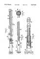
- FIG. 1is an exploded view of an embodiment of the implant of the invention, showing the threaded shaft portion separated from the sleeve before it is non-removably connected to the sleeve, with the sleeve shown partially in cross-section.
- FIG. 2is a pictorial representation of the device of FIG. 1, with the sleeve and the threaded shaft portion nonremovably connected together.
- FIG. 3is a magnified view of the device shown in FIG. 2, but with the sleeve portion of the device shown partially in cross-section.
- FIG. 4is a cross-sectional view taken along the lines 4--4 in FIG. 2.
- FIG. 5is a pictorial representation of an embodiment of the driver of the invention, showing the locking means located on the handle of the device which locks into a preferably knurled portion of the outer cylindrical portion, the outer cylindrical portion having a special driver means at its distal end, and showing the inner rod portion having another special driver means at its distal end.
- FIG. 6is a view partially in cross-section of the driver shown in FIG. 5 (with the driver in its locked position).
- FIG. 7is a pictorial representation showing (with use of inner phantom lines) the driver means located at the distal end of the inner rod of the driver just prior to its contacting the proximal end of the threaded shank portion of the implant of the invention, at a point in time when the implant of the invention has its maximum length.
- FIG. 8is an end view of FIG. 3 (viewed along lines 8--8 in FIG. 3).
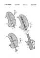
- FIG. 9is a pictorial representation in cross-section illustrating the first step in the method of inserting the implant of the invention into a fractured bone, a drill bit shown drilling a hole into and through the proximal portion of the fracture and into the distal portion of the fracture.
- FIG. 10is a pictorial representation in cross-section illustrating the second step in the method of inserting the implant of the invention, a second drill bit having a larger diameter than that shown in FIG. 9 being used to "overdrill” (i.e., to accommodate the shaft of the sleeve) the proximal portion of the fracture.
- FIG. 11is a pictorial representation in cross-section showing the distal portion of the threaded shank portion of the implant being inserted into the distal portion of the fracture by means of the driver means on the distal end of the inner rod of the driver (preferably together with the driver means on the distal end of the cylinder), these two driver means being mated with recesses in the implant, prior to the sleeve being threaded down onto the proximal portion of the threaded shank portion of the implant of the invention (the fracture being at this time not compressed).
- the driver of the invention at this timeis in its locked position.
- FIG. 12is a pictorial representation (partially in cross-section) showing the driver in its unlocked position with the driver means located at the distal end of the inner rod positioned adjacent to and engaged with the proximal end of the threaded shank portion and with the driver means located at the distal end of the outer cylindrical portion being located adjacent to and engaged with the recess in the head of the sleeve portion of the implant of the device of the invention.
- An arrowindicates the clockwise direction in which the driver will be turned so as to insert the implant of the invention.
- FIG. 13is a pictorial representation of the implant of the invention after it has been fully inserted into a fracture and after the fracture has been compressed by the implant and after the driver has been removed.
- a threaded shank portion 22comprises a proximal threaded shank portion 24 and a distal threaded shank portion 26.
- the threads of proximal threaded shank portion 24 and distal threaded shank portion 26are not identical, but rather are of different diameters, pitches, and profiles. This is preferred but is not required.
- the directions of the threads in this embodimentare the same (both preferably are the same and both preferably are righthanded). In the embodiment shown in FIG.
- the length of the proximal threaded shank portion 24(preferably machine thread) is slightly shorter than the length of the distal threaded shank portion 26 (preferably bone thread). These relative lengths can be modified as desired, depending upon the intended use.
- the diameter 32 of the proximal threaded shank portion 24is slightly smaller than the diameter 34 of the distal threaded shank portion 26.
- a cutout 38is present at the proximal end 36 of proximal threaded shank portion 24 and in a preferred embodiment is half-cylindrical.
- the cutout 38can (if desired) have a rounded boundary 40.
- sleeve 42is shown separated from threaded shank portion 22, but this is at a time prior to the assembly of the implant of the invention.
- Sleeve 42has an outer diameter 44 and an inner diameter 46.
- Sleeve 42has internal threading 48 which mates with and threads with threading 25 of proximal threaded shank portion 24.
- Sleeve 42has an outer surface 50 which is substantially smooth.
- a head 52At the proximal end of sleeve 42 is a head 52 which is integral with sleeve 42. Head 52 has an outer diameter 54 and has a recess 56 therein. Recess 56 is preferably in the shape of a slot but can be, if desired, of other shapes, for example, hexagonal.
- Outer diameter 54will be larger than the diameter drilled in the proximal portion of the bone fracture during "overdrilling".
- the length 28 of proximal threaded shaft 24should be no longer than the length of the sleeve 42 without including the length of head 52.
- the number of threads in internal threading 48should be the minimum number of threads to function properly as a machine thread.
- the hole 58should be located just proximal to the last thread in internal threading 48.
- sleeve 42is shown partially threaded down onto proximal threaded shank portion 24. Proximal threaded shank portion 24 and distal threaded shank portion 26 are integral with each other.
- a hole 58 in sleeve 42is shown. Prior to assembly of the implant 20, a hole 58 is drilled into sleeve 42. After the sleeve 42 is assembled together with the threaded shank portion 22, the threaded shank portion 22 and the sleeve 42 are nonremovably connected together when manufactured by any suitable means, for example, by deforming some of the threads 25 through hole 58 so that sleeve 42 cannot become disengaged from threaded shank portion 22. Another alternative is to deform proximal end 36 so as to prevent disengagement of sleeve 42 from threaded shank portion 22.
- FIG. 3shown is a magnified view of the device of FIG. 2, with a portion of sleeve 52 shown in cross-section. Cutout 38 is located at the proximal end 36 of proximal thread shaft portion 24, and hole 58 is located in sleeve 42. Proximal threaded shaft portion 24 is threaded within and engaged with internal threading 48 of sleeve 42.
- proximal threaded shank portion 24is threadably engaged within internal threading 48 of sleeve 42.
- Areas 59are multiple areas of deformed threads which prevent future disengagement of the device.
- FIG. 5is shown a driver which is especially suitable for inserting and removing the implant of the invention.
- Driver 60has a handle 62, which is fixedly attached to an inner rod 64.
- Handle 62has a slidable portion 66, which can be in the shape of any of a variety of structures, for example (as shown) a knurled portion of a cylinder or a knob.
- a small rod 68 fixed theretocan be positioned so that it fits into one of a multiplicity of holes 70 in (preferably) knurled cylindrical portion 72.
- Knurled cylindrical portion 72is integral with outer cylindrical portion 74, which fits over inner rod 64 and which has located at its distal-most end 76 a tab 78 for mating with the recess 56 in the head 52 of the sleeve 42.
- Outer cylindrical portion 74can be in a locked position, wherein small rod 68 is locked within a hole 70.
- Outer cylindrical portion 74can alternatively be in an unlocked position, wherein slidable portion 66 is retracted in a proximal direction so that small rod 68 is not engaged within a hole 70.
- Tab 78is integral with distal-most end 76 of outer cylindrical portion 74. Locking mechanism 78 is shaped so that it can mate with recess 56 in head 52.
- the distal-most end 82 of inner rod 64is shaped so that it can mate and engage with cutout 38 at proximal end 36 of proximal threaded shank portion 24.
- Outer cylindrical portion 74can have at least two integrally attached portions having different diameters 84, 86, if desired; or alternatively, it can have one diameter throughout, which is integrally attached to preferably knurled cylindrical portion 72.
- knurled cylindrical portion 72has a multiplicity of holes 70 therein, into any one of which rod 68 can be engaged.
- FIG. 8an end view taken along the lines 8--8 in FIG. 3 shows head 52 of sleeve 42 with recess 56 therein and shows also proximal threaded shank portion 24 having proximal end 36 and cutout 38 (which is preferably in the shape of a half-cylinder) therein.
- a proximal portion 88 of a fractured bone and a distal portion 90 of that boneare shown separated from each other.
- a holeis drilled into and through the proximal portion of the fractured bone and into the distal portion of the bone by a drill bit 92.
- FIG. 10a larger diameter drill bit 94 is illustrated within that same bone so as to enlarge the hole in the proximal portion of that fractured bone thereby "overdrilling" the proximal portion of that bone to accommodate the shaft 42 of the sleeve.
- the distal threaded shank portion 26 of the implant 20is inserted into the distal portion 90 of the fracture and into its optimal position in the bone.
- the distal-most end 82 of inner rod 64is shown engaged with the end 36 and cutout 38 of proximal threaded shank portion 24.
- Tab 78meshes with and engages with recess 56 within head 52.
- slidable portion 66is retracted so that it is at its proximal-most position, small rod 68 (attached thereto) is retracted from hole 70, and knurled cylindrical portion 72 is now free to rotate.
- knurled cylindrical portion 72is rotated in a clockwise direction as indicated, the sleeve 42 of the implant 20 advances so as to shorten the overall length of the implant 30 and so as thereby to compress the fracture as force is exerted by head 54 down onto bone where head 54 contacts the bone.
- the implant 20can be allowed to remain within the bone as desired. If its removal is desired, the driver 60 especially suitable for inserting the implant can be profitably used for removing the implant. In this event, the reverse of the procedure just described is used, with the distal-most end 82 of inner rod 64 being positioned to abut against and engage with proximal end 36 of proximal threaded shank portion 24 and with cutout 38 and (at the same time) such that locking mechanism 78 abuts against and engages with recess 56 in head 52 of sleeve 42 of implant 20.
- the driver 60is at this time in its unlocked position and knurled cylindrical portion 72 is rotated in a clockwise or counter-clockwise direction to line up the nearest hole 70 with the rod 68.
- the screwdriveris then locked and turned as a unit counterclockwise to remove the screw.
- the implant of the inventioncomprises a special threaded shank portion and a special internally threaded sleeve portion, which parts are connected together in a non-removable relationship
- an implanthaving many advantages results.
- the implantcan be easily inserted as a one-piece device, without the need for assembling any parts together during surgery. Likewise, the device can be easily unscrewed and removed.
- the slot (or other suitable shape) in the head of the sleeve, together with the feature of the specially shaped proximal end of the threaded shank portion of the implant which fits within the sleeve,results in the advantages that the threaded shaft portion can be held stationary while the screw is being shortened, causing bone compression.
- the devicecan be made in a variety of sizes so that it can be used to repair fractures of the small bones of the hand and foot (including diaphaseal, metaphysal, epiphyseal and articular).
- the devicecan be used for arthrodesis of small bones, for repair of avulsion fractures of the knee, elbow, shoulder, or any joint with tendenous attachment injury, or for lagging fracture fragments of long bones.
- the deviceis especially suitable for use as a small lag screw and reduction device.
- the implantcan be used either alone or with plates and washers, and the implant generates bone compression by itself.
- the driver of the inventionwhich is especially suitable for inserting and removing the implant of the invention has also several advantages.
- the first driver means located on the inner rodfits securely within the sleeve of the implant and mates with the proximal end of the threaded shank portion of the implant, so as to enable the threaded shank portion of the implant to be inserted into and through the proximal side of the fracture and into the distal side of the fracture and also enables the driver to prevent slippage of the driver while the outer cylindrical portion of the driver having a second driver means is used to thread the sleeve onto the implant so as to compress the fracture. That is, both the functions of inserting the screw and then lagging the fracture are accomplished by the same implant.
Landscapes
- Health & Medical Sciences (AREA)
- Orthopedic Medicine & Surgery (AREA)
- Engineering & Computer Science (AREA)
- Life Sciences & Earth Sciences (AREA)
- Surgery (AREA)
- Molecular Biology (AREA)
- Veterinary Medicine (AREA)
- Nuclear Medicine, Radiotherapy & Molecular Imaging (AREA)
- Public Health (AREA)
- Biomedical Technology (AREA)
- Heart & Thoracic Surgery (AREA)
- Medical Informatics (AREA)
- General Health & Medical Sciences (AREA)
- Animal Behavior & Ethology (AREA)
- Neurology (AREA)
- Mechanical Engineering (AREA)
- Multimedia (AREA)
- Signal Processing (AREA)
- Dental Prosthetics (AREA)
- Prostheses (AREA)
- Surgical Instruments (AREA)
- Dowels (AREA)
- Electrotherapy Devices (AREA)
- Details Of Spanners, Wrenches, And Screw Drivers And Accessories (AREA)
- Formation And Processing Of Food Products (AREA)
- Encapsulation Of And Coatings For Semiconductor Or Solid State Devices (AREA)
- Transmission Devices (AREA)
Abstract
Description
Claims (6)
Priority Applications (18)
| Application Number | Priority Date | Filing Date | Title |
|---|---|---|---|
| US07/664,905US5217462A (en) | 1991-03-05 | 1991-03-05 | Screw and driver |
| PCT/US1992/000760WO1992015257A1 (en) | 1991-03-05 | 1992-02-07 | Screw and driver |
| AT94201085TATE139102T1 (en) | 1991-03-05 | 1992-02-07 | DEVICE FOR INSERTING AN IMPLANT |
| EP92908388AEP0574517B1 (en) | 1991-03-05 | 1992-02-07 | Screw and driver |
| DE69211561TDE69211561T2 (en) | 1991-03-05 | 1992-02-07 | Device for inserting an implant |
| CA002104680ACA2104680C (en) | 1991-03-05 | 1992-02-07 | Screw and driver |
| ES94201085TES2088310T3 (en) | 1991-03-05 | 1992-02-07 | DEVICE TO INSERT AN IMPLANT. |
| DE9290023UDE9290023U1 (en) | 1991-03-05 | 1992-02-07 | Screw implantation device |
| KR1019930702627AKR0145340B1 (en) | 1991-03-05 | 1992-02-07 | Screwdriver |
| CA002206764ACA2206764C (en) | 1991-03-05 | 1992-02-07 | Implant inserting device |
| AT92908388TATE121922T1 (en) | 1991-03-05 | 1992-02-07 | SCREW AND SCREWDRIVER. |
| JP4508123AJPH0773586B2 (en) | 1991-03-05 | 1992-02-07 | Screw and driver |
| AU15824/92AAU648723B2 (en) | 1991-03-05 | 1992-02-07 | Screw and driver |
| DE69202337TDE69202337T2 (en) | 1991-03-05 | 1992-02-07 | Screw and screwdriver. |
| EP94201085AEP0611018B1 (en) | 1991-03-05 | 1992-02-07 | Device for inserting an implant |
| ES92908388TES2072146T3 (en) | 1991-03-05 | 1992-02-07 | SCREW AND SCREWDRIVER. |
| IE920693AIE67167B1 (en) | 1991-03-05 | 1992-03-04 | Screw and driver |
| US08/222,517US5498265A (en) | 1991-03-05 | 1994-04-01 | Screw and driver |
Applications Claiming Priority (1)
| Application Number | Priority Date | Filing Date | Title |
|---|---|---|---|
| US07/664,905US5217462A (en) | 1991-03-05 | 1991-03-05 | Screw and driver |
Related Child Applications (1)
| Application Number | Title | Priority Date | Filing Date |
|---|---|---|---|
| US2181593AContinuation | 1991-03-05 | 1993-02-24 |
Publications (1)
| Publication Number | Publication Date |
|---|---|
| US5217462Atrue US5217462A (en) | 1993-06-08 |
Family
ID=24667936
Family Applications (1)
| Application Number | Title | Priority Date | Filing Date |
|---|---|---|---|
| US07/664,905Expired - LifetimeUS5217462A (en) | 1991-03-05 | 1991-03-05 | Screw and driver |
Country Status (11)
| Country | Link |
|---|---|
| US (1) | US5217462A (en) |
| EP (2) | EP0574517B1 (en) |
| JP (1) | JPH0773586B2 (en) |
| KR (1) | KR0145340B1 (en) |
| AT (2) | ATE121922T1 (en) |
| AU (1) | AU648723B2 (en) |
| CA (2) | CA2104680C (en) |
| DE (3) | DE69202337T2 (en) |
| ES (2) | ES2072146T3 (en) |
| IE (1) | IE67167B1 (en) |
| WO (1) | WO1992015257A1 (en) |
Cited By (153)
| Publication number | Priority date | Publication date | Assignee | Title |
|---|---|---|---|---|
| WO1995003745A1 (en)* | 1993-08-03 | 1995-02-09 | Howmedica Inc. | Ratcheting compression device |
| US5549677A (en)* | 1991-05-13 | 1996-08-27 | Walter Durr | Implant with pressing surface |
| US5643264A (en)* | 1995-09-13 | 1997-07-01 | Danek Medical, Inc. | Iliac screw |
| US5674224A (en)* | 1994-11-18 | 1997-10-07 | Howell; Stephen M. | Bone mulch screw assembly for endosteal fixation of soft tissue grafts and method for using same |
| EP0853929A2 (en) | 1997-01-16 | 1998-07-22 | Buechel-Pappas Trust | Orthopedic prosthesis employing bone screws and cement |
| US5868749A (en)* | 1996-04-05 | 1999-02-09 | Reed; Thomas M. | Fixation devices |
| US5893850A (en)* | 1996-11-12 | 1999-04-13 | Cachia; Victor V. | Bone fixation device |
| US5904685A (en)* | 1997-04-11 | 1999-05-18 | Stryker Corporation | Screw sheath |
| US6004327A (en)* | 1993-08-03 | 1999-12-21 | Stryker Technologies Corporation | Ratcheting compression device |
| US6053935A (en)* | 1996-11-08 | 2000-04-25 | Boston Scientific Corporation | Transvaginal anchor implantation device |
| US6077216A (en)* | 1991-12-03 | 2000-06-20 | Boston Scientific Technology, Inc. | Device for transvaginally suspending the bladder neck |
| US6096041A (en)* | 1998-01-27 | 2000-08-01 | Scimed Life Systems, Inc. | Bone anchors for bone anchor implantation device |
| US6241736B1 (en) | 1998-05-12 | 2001-06-05 | Scimed Life Systems, Inc. | Manual bone anchor placement devices |
| US6264676B1 (en) | 1996-11-08 | 2001-07-24 | Scimed Life Systems, Inc. | Protective sheath for transvaginal anchor implantation devices |
| US6302887B1 (en)* | 1998-07-20 | 2001-10-16 | Joseph John Spranza | Hardware for high strength fastening of bone |
| US6355043B1 (en)* | 1999-03-01 | 2002-03-12 | Sulzer Orthopedics Ltd. | Bone screw for anchoring a marrow nail |
| US6436100B1 (en) | 1998-08-07 | 2002-08-20 | J. Lee Berger | Cannulated internally threaded bone screw and reduction driver device |
| WO2002078555A1 (en)* | 2001-03-30 | 2002-10-10 | Triage Medical, Inc. | Distal bone anchors for bone fixation with secondary compression |
| US6511481B2 (en) | 2001-03-30 | 2003-01-28 | Triage Medical, Inc. | Method and apparatus for fixation of proximal femoral fractures |
| US20030055433A1 (en)* | 2000-02-29 | 2003-03-20 | Christian Krenkel | Endo-distractor |
| US20030120277A1 (en)* | 1998-08-07 | 2003-06-26 | Berger J. Lee | Cannulated internally threaded bone screw with aperatured insert |
| US6585740B2 (en) | 1998-11-26 | 2003-07-01 | Synthes (U.S.A.) | Bone screw |
| US6632224B2 (en) | 1996-11-12 | 2003-10-14 | Triage Medical, Inc. | Bone fixation system |
| US6648890B2 (en) | 1996-11-12 | 2003-11-18 | Triage Medical, Inc. | Bone fixation system with radially extendable anchor |
| US20030216743A1 (en)* | 2002-05-16 | 2003-11-20 | Keith Hoffman | Bone anchor implantation device |
| US6660010B2 (en) | 1998-01-27 | 2003-12-09 | Scimed Life Systems, Inc. | Bone anchor placement device with recessed anchor mount |
| US20040015172A1 (en)* | 2000-11-10 | 2004-01-22 | Lutz Biedermann | Bone screw |
| US6685706B2 (en) | 2001-11-19 | 2004-02-03 | Triage Medical, Inc. | Proximal anchors for bone fixation system |
| US20040106925A1 (en)* | 2002-11-25 | 2004-06-03 | Culbert Brad S. | Soft tissue anchor and method of using same |
| US20040127906A1 (en)* | 2002-07-19 | 2004-07-01 | Culbert Brad S. | Method and apparatus for spinal fixation |
| US6770075B2 (en) | 2001-05-17 | 2004-08-03 | Robert S. Howland | Spinal fixation apparatus with enhanced axial support and methods for use |
| US20040210227A1 (en)* | 2003-02-03 | 2004-10-21 | Kinetikos Medical, Inc. | Compression screw apparatuses, systems and methods |
| US20050033433A1 (en)* | 1999-05-05 | 2005-02-10 | Michelson Gary K. | Implant having upper and lower extended members and method for use thereof |
| US6887243B2 (en) | 2001-03-30 | 2005-05-03 | Triage Medical, Inc. | Method and apparatus for bone fixation with secondary compression |
| US20050101961A1 (en)* | 2003-11-12 | 2005-05-12 | Huebner Randall J. | Bone screws |
| US20050143734A1 (en)* | 1996-11-12 | 2005-06-30 | Cachia Victor V. | Bone fixation system with radially extendable anchor |
| US6936052B2 (en) | 2001-03-09 | 2005-08-30 | Boston Scientific Scimed, Inc. | System for implanting an implant and method thereof |
| US6951561B2 (en) | 2003-05-06 | 2005-10-04 | Triage Medical, Inc. | Spinal stabilization device |
| US7025772B2 (en) | 2001-03-09 | 2006-04-11 | Scimed Life Systems, Inc. | System for implanting an implant and method thereof |
| US20060089647A1 (en)* | 2004-08-20 | 2006-04-27 | Culbert Brad S | Method and apparatus for delivering an agent |
| US20060095040A1 (en)* | 2004-02-23 | 2006-05-04 | Andre Schlienger | Bone screw |
| US7070601B2 (en) | 2003-01-16 | 2006-07-04 | Triage Medical, Inc. | Locking plate for bone anchors |
| US20060229622A1 (en)* | 1993-01-21 | 2006-10-12 | Huebner Randall J | System for fusing joints |
| US20060271054A1 (en)* | 2005-05-10 | 2006-11-30 | Sucec Matthew C | Bone connector with pivotable joint |
| US20070016191A1 (en)* | 2004-12-08 | 2007-01-18 | Culbert Brad S | Method and apparatus for spinal stabilization |
| US20070149973A1 (en)* | 2003-06-27 | 2007-06-28 | Medicrea Technologies | Vertebral osteosynthesis equipment |
| US20070162026A1 (en)* | 2001-10-18 | 2007-07-12 | Fxdevices Llc | System and method for a cap used in the fixation of bone fractures |
| US20070260248A1 (en)* | 2001-10-18 | 2007-11-08 | Fxdevices, Llc | Cannulated bone screw system and method |
| US20070276382A1 (en)* | 2006-05-09 | 2007-11-29 | Synthes (U.S.A.) | Nail System and Method for An Olecranon Osteotomy |
| US7314467B2 (en) | 2002-04-24 | 2008-01-01 | Medical Device Advisory Development Group, Llc. | Multi selective axis spinal fixation system |
| US7361138B2 (en) | 2003-07-31 | 2008-04-22 | Scimed Life Systems, Inc. | Bioabsorbable casing for surgical sling assembly |
| US20080119855A1 (en)* | 2005-02-19 | 2008-05-22 | Aesculap Ag & Co. Kg | Orthopedic fixation system |
| US20080147126A1 (en)* | 2001-10-18 | 2008-06-19 | Fxdevices, Llc | System and method for a cap used in the fixation of bone fractures |
| US20080147127A1 (en)* | 2001-10-18 | 2008-06-19 | Fxdevices, Llc | Bone screw system and method |
| US7402133B2 (en) | 2002-12-17 | 2008-07-22 | Boston Scientific Scimed, Inc. | Spacer for sling delivery system |
| US20080177291A1 (en)* | 2006-11-01 | 2008-07-24 | Jensen David G | Orthopedic connector system |
| US20080195233A1 (en)* | 2006-10-13 | 2008-08-14 | Irene Ferrari | Ankle prosthesis for the arthrodesis of the calcaneum |
| US20080213714A1 (en)* | 2005-11-11 | 2008-09-04 | Alexander Knoch | Rotary Furnace Burner |
| US20080243132A1 (en)* | 2001-10-18 | 2008-10-02 | Fx Devices, Llc | Tensioning system and method for the fixation of bone fractures |
| US20080243191A1 (en)* | 2001-10-18 | 2008-10-02 | Fx Devices, Llc | Adjustable bone plate fixation system and metho |
| US20080255621A1 (en)* | 2004-06-02 | 2008-10-16 | Synthes (U.S.A.) | Sleeve |
| US20080269807A1 (en)* | 2007-04-19 | 2008-10-30 | Stryker Trauma Gmbh | Hip fracture device with static locking mechanism allowing compression |
| US20080269768A1 (en)* | 2007-04-10 | 2008-10-30 | Stryker Trauma Sa | Bone screw holding device |
| US20080269752A1 (en)* | 2007-04-19 | 2008-10-30 | Stryker Trauma Gmbh | Hip fracture device with barrel and end cap for load control |
| US20080306537A1 (en)* | 2007-06-08 | 2008-12-11 | Interventional Spine, Inc. | Method and apparatus for spinal stabilization |
| EP1755468A4 (en)* | 2004-06-02 | 2009-01-21 | Synthes Gmbh | IMPLANT ASSEMBLY DEVICE |
| US20090036893A1 (en)* | 2007-08-02 | 2009-02-05 | Proactive Orthopedic, Llc | Fixation and alignment device and method used in orthopaedic surgery |
| US20090048606A1 (en)* | 2001-10-18 | 2009-02-19 | Fxdevices Llc | Guide system and method for the fixation of bone fractures |
| US20090131990A1 (en)* | 2001-10-18 | 2009-05-21 | Kishore Tipirneni | Bone screw system and method |
| US20090131991A1 (en)* | 2001-10-18 | 2009-05-21 | Kishore Tipirneni | System and method for the fixation of bone fractures |
| US20090131936A1 (en)* | 2001-10-18 | 2009-05-21 | Kishore Tipirneni | System and method for the fixation of bone fractures |
| US20090138051A1 (en)* | 2007-07-11 | 2009-05-28 | Stryker Trauma Gmbh | Device for creating a bone implant |
| US20090171403A1 (en)* | 2001-10-18 | 2009-07-02 | Lagwire, Llc | Method for the fixation of bone structures |
| US20090192551A1 (en)* | 2008-01-24 | 2009-07-30 | Jason Cianfrani | Facet Fixation Prosthesis |
| US20090192512A1 (en)* | 2008-01-28 | 2009-07-30 | Sommers Mark B | Bone nail |
| US20090254129A1 (en)* | 2007-04-30 | 2009-10-08 | Kishore Tipirneni | Bone screw system and method for the fixation of bone fractures |
| US20090275954A1 (en)* | 2008-04-30 | 2009-11-05 | Phan Christopher U | Apparatus and methods for inserting facet screws |
| US20090306718A1 (en)* | 2001-10-18 | 2009-12-10 | Orthoip, Llc | Filament and cap systems and methods for the fixation of bone fractures |
| US7648523B2 (en) | 2004-12-08 | 2010-01-19 | Interventional Spine, Inc. | Method and apparatus for spinal stabilization |
| US20100268285A1 (en)* | 2001-10-18 | 2010-10-21 | Orthoip, Llc | Bone screw system and method for the fixation of bone fractures |
| US20100312292A1 (en)* | 2001-10-18 | 2010-12-09 | Orthoip, Llc | Lagwire system and method for the fixation of bone fractures |
| US20100331892A1 (en)* | 2009-06-30 | 2010-12-30 | Fell Barry M | Bone repair system and method |
| US20110112580A1 (en)* | 2003-06-27 | 2011-05-12 | Medicrea Technologies | Vertebral osteosynthesis equipment |
| US20110166612A1 (en)* | 2008-08-19 | 2011-07-07 | Corporació Sanitària Parc Taulí | Device for use in surgical treatment of funnel chest and method of treatment |
| US20110172668A1 (en)* | 2010-01-13 | 2011-07-14 | Frake Paul C | Intramedullary Mandibular Condyle Implants and Method for Application of the Same |
| US8033983B2 (en) | 2001-03-09 | 2011-10-11 | Boston Scientific Scimed, Inc. | Medical implant |
| EP2430993A2 (en) | 2005-12-28 | 2012-03-21 | Intrinsic Therapeutics, Inc. | Devices and methods for bone anchoring |
| US8409257B2 (en) | 2010-11-10 | 2013-04-02 | Warsaw Othopedic, Inc. | Systems and methods for facet joint stabilization |
| US20130211468A1 (en)* | 1993-01-21 | 2013-08-15 | Acumed Llc | Axial tension screw |
| US8535322B1 (en)* | 2012-11-07 | 2013-09-17 | Roy Y. Powlan | Hip nail and inertial insertion tooling |
| CN103826544A (en)* | 2011-03-22 | 2014-05-28 | 史密夫和内修有限公司 | Anchor system and delivery device for use therewith |
| US20140222087A1 (en)* | 2012-11-13 | 2014-08-07 | Louis E. Greenberg | Orthopedic implant having non-circular cross section and method of use thereof |
| US8882816B2 (en) | 2007-08-02 | 2014-11-11 | Proactive Orthopedics, Llc | Fixation and alignment device and method used in orthopaedic surgery |
| US20140343616A1 (en)* | 2013-04-22 | 2014-11-20 | Daniel Sellers | Arthrodesis compression device |
| US9039765B2 (en) | 2011-01-21 | 2015-05-26 | Warsaw Orhtopedic, Inc. | Implant system and method for stabilization of a sacro-iliac joint |
| US9060809B2 (en) | 2001-10-18 | 2015-06-23 | Orthoip, Llc | Lagwire system and method for the fixation of bone fractures |
| US9095444B2 (en) | 2009-07-24 | 2015-08-04 | Warsaw Orthopedic, Inc. | Implant with an interference fit fastener |
| US9101399B2 (en) | 2011-12-29 | 2015-08-11 | Proactive Orthopedics, Llc | Anchoring systems and methods for surgery |
| US9138219B2 (en) | 2010-12-29 | 2015-09-22 | Tarsus Medical Inc. | Methods and devices for treating a syndesmosis injury |
| US9161794B2 (en) | 2011-04-14 | 2015-10-20 | Globus Medical, Inc. | Expanding spinal anchor |
| US9522070B2 (en) | 2013-03-07 | 2016-12-20 | Interventional Spine, Inc. | Intervertebral implant |
| US9522028B2 (en) | 2013-07-03 | 2016-12-20 | Interventional Spine, Inc. | Method and apparatus for sacroiliac joint fixation |
| US20160374661A1 (en)* | 2009-10-28 | 2016-12-29 | Smith & Nephew, Inc. | Threaded suture anchor |
| US9585703B2 (en) | 2014-09-19 | 2017-03-07 | Agent Medical, Llc | Intramedullary compression screw system |
| US20170164954A1 (en)* | 2015-12-11 | 2017-06-15 | IntraFuse, LLC | Flexible tap |
| US9839530B2 (en) | 2007-06-26 | 2017-12-12 | DePuy Synthes Products, Inc. | Highly lordosed fusion cage |
| US9883951B2 (en) | 2012-08-30 | 2018-02-06 | Interventional Spine, Inc. | Artificial disc |
| US9895236B2 (en) | 2010-06-24 | 2018-02-20 | DePuy Synthes Products, Inc. | Enhanced cage insertion assembly |
| US9907597B2 (en)* | 2008-08-12 | 2018-03-06 | Charles E. Kollmer | Bone compression system and associated methods |
| US9913727B2 (en) | 2015-07-02 | 2018-03-13 | Medos International Sarl | Expandable implant |
| US9931223B2 (en) | 2008-04-05 | 2018-04-03 | DePuy Synthes Products, Inc. | Expandable intervertebral implant |
| US9993349B2 (en) | 2002-06-27 | 2018-06-12 | DePuy Synthes Products, Inc. | Intervertebral disc |
| US10058433B2 (en) | 2012-07-26 | 2018-08-28 | DePuy Synthes Products, Inc. | Expandable implant |
| US10231767B2 (en) | 2013-03-15 | 2019-03-19 | The Penn State Research Foundation | Bone repair system, kit and method |
| WO2019055404A1 (en)* | 2017-09-12 | 2019-03-21 | Mcginley Engineered Solutions, Llc | Variable length surgical screw |
| US10390963B2 (en) | 2006-12-07 | 2019-08-27 | DePuy Synthes Products, Inc. | Intervertebral implant |
| US10398563B2 (en) | 2017-05-08 | 2019-09-03 | Medos International Sarl | Expandable cage |
| US10433977B2 (en) | 2008-01-17 | 2019-10-08 | DePuy Synthes Products, Inc. | Expandable intervertebral implant and associated method of manufacturing the same |
| US10500062B2 (en) | 2009-12-10 | 2019-12-10 | DePuy Synthes Products, Inc. | Bellows-like expandable interbody fusion cage |
| US10512734B2 (en)* | 2014-04-03 | 2019-12-24 | Versago Vascular Access, Inc. | Devices and methods for installation and removal of a needle tip of a needle |
| US10531905B2 (en) | 2016-04-19 | 2020-01-14 | Globus Medical, Inc. | Implantable compression screws |
| US10537436B2 (en) | 2016-11-01 | 2020-01-21 | DePuy Synthes Products, Inc. | Curved expandable cage |
| US10548741B2 (en) | 2010-06-29 | 2020-02-04 | DePuy Synthes Products, Inc. | Distractible intervertebral implant |
| US10575883B2 (en) | 2014-12-15 | 2020-03-03 | Smith & Nephew, Inc. | Active fracture compression implants |
| US20200155211A1 (en)* | 2017-05-04 | 2020-05-21 | Orthofix S.R.L. | Bone Screw for the Treatment of Bone Collapses or Deformations, in the Case of the Charcot Foot, and Insertion Instrument of Anti-Migration Elements into the Bone Screw |
| US10835728B2 (en) | 2009-12-04 | 2020-11-17 | Versago Vascular Access, Inc. | Vascular access port |
| US10888433B2 (en) | 2016-12-14 | 2021-01-12 | DePuy Synthes Products, Inc. | Intervertebral implant inserter and related methods |
| US10905866B2 (en) | 2014-12-18 | 2021-02-02 | Versago Vascular Access, Inc. | Devices, systems and methods for removal and replacement of a catheter for an implanted access port |
| US10940016B2 (en) | 2017-07-05 | 2021-03-09 | Medos International Sarl | Expandable intervertebral fusion cage |
| US11058815B2 (en) | 2017-12-21 | 2021-07-13 | Versago Vascular Access, Inc. | Medical access ports, transfer devices and methods of use thereof |
| US11154687B2 (en) | 2014-12-18 | 2021-10-26 | Versago Vascular Access, Inc. | Catheter patency systems and methods |
| US11224467B2 (en) | 2016-02-26 | 2022-01-18 | Activortho, Inc. | Active compression apparatus, methods of assembly and methods of use |
| US11229781B2 (en) | 2015-07-14 | 2022-01-25 | Versago Vascular Access, Inc. | Medical access ports, transfer devices and methods of use thereof |
| US11234746B2 (en) | 2016-02-26 | 2022-02-01 | Activortho, Inc. | Active compression apparatus, methods of assembly and methods of use |
| US11278335B2 (en)* | 2016-04-19 | 2022-03-22 | Globus Medical, Inc. | Implantable compression screws |
| US11344424B2 (en) | 2017-06-14 | 2022-05-31 | Medos International Sarl | Expandable intervertebral implant and related methods |
| US11350976B2 (en)* | 2019-11-06 | 2022-06-07 | DePuy Synthes Products, Inc. | System and method for treating a bone |
| US11382675B2 (en) | 2020-04-01 | 2022-07-12 | EKTA-Sofia Ltd. | Surgical method for biplane screw fixation of femoral neck fractures (calcar buttressed screw fixation) |
| US11426290B2 (en) | 2015-03-06 | 2022-08-30 | DePuy Synthes Products, Inc. | Expandable intervertebral implant, system, kit and method |
| US11426286B2 (en) | 2020-03-06 | 2022-08-30 | Eit Emerging Implant Technologies Gmbh | Expandable intervertebral implant |
| US11446156B2 (en) | 2018-10-25 | 2022-09-20 | Medos International Sarl | Expandable intervertebral implant, inserter instrument, and related methods |
| US11452607B2 (en) | 2010-10-11 | 2022-09-27 | DePuy Synthes Products, Inc. | Expandable interspinous process spacer implant |
| US11510788B2 (en) | 2016-06-28 | 2022-11-29 | Eit Emerging Implant Technologies Gmbh | Expandable, angularly adjustable intervertebral cages |
| US11596523B2 (en) | 2016-06-28 | 2023-03-07 | Eit Emerging Implant Technologies Gmbh | Expandable and angularly adjustable articulating intervertebral cages |
| US11612491B2 (en) | 2009-03-30 | 2023-03-28 | DePuy Synthes Products, Inc. | Zero profile spinal fusion cage |
| US11752009B2 (en) | 2021-04-06 | 2023-09-12 | Medos International Sarl | Expandable intervertebral fusion cage |
| US11844557B2 (en) | 2020-05-12 | 2023-12-19 | Globus Medical, Inc. | Locking variable length compression screw |
| US11850160B2 (en) | 2021-03-26 | 2023-12-26 | Medos International Sarl | Expandable lordotic intervertebral fusion cage |
| US11883296B2 (en) | 2016-11-07 | 2024-01-30 | Endospine, S.L. | Process of bone creation between adjacent vertebrae |
| US11911287B2 (en) | 2010-06-24 | 2024-02-27 | DePuy Synthes Products, Inc. | Lateral spondylolisthesis reduction cage |
| USRE49973E1 (en) | 2013-02-28 | 2024-05-21 | DePuy Synthes Products, Inc. | Expandable intervertebral implant, system, kit and method |
| US12090064B2 (en) | 2022-03-01 | 2024-09-17 | Medos International Sarl | Stabilization members for expandable intervertebral implants, and related systems and methods |
| US12440346B2 (en) | 2023-03-31 | 2025-10-14 | DePuy Synthes Products, Inc. | Expandable intervertebral implant |
Families Citing this family (19)
| Publication number | Priority date | Publication date | Assignee | Title |
|---|---|---|---|---|
| FR2699065B1 (en)* | 1992-12-10 | 1995-03-10 | Hardy Jean Marie | Self-compressing screw for the treatment of epiphyseal and / or osteochondral fractures. |
| IL105183A (en)* | 1993-03-28 | 1996-07-23 | Yehiel Gotfried | Surgical device for connection of fractured bones |
| FR2728778B1 (en)* | 1994-12-30 | 1998-08-21 | Diebold Patrice Francois | TRANS- OR INTRA-BONE IMPLANT FOR THE APPROXIMATION AND PRESSURIZATION OF BONE AND ANCILLARY FRAGMENTS FOR THE IMPLEMENTATION OF THIS IMPLANT |
| WO1996039974A1 (en)* | 1995-06-07 | 1996-12-19 | Implex Corporation | Femoral head core channel filling prosthesis |
| JPH0956728A (en)* | 1995-08-24 | 1997-03-04 | Nakanishi:Kk | Screw driver |
| DE10101267B4 (en)* | 2001-01-12 | 2007-02-01 | Stryker Leibinger Gmbh & Co. Kg | Compression bone screw and compression bone screw system |
| KR20030037616A (en)* | 2001-11-07 | 2003-05-14 | 주식회사 코렌텍 | Free length hip pin |
| DE10301691B4 (en)* | 2003-01-17 | 2006-10-12 | Stryker Leibinger Gmbh & Co. Kg | Socket handle and socket system |
| US7044953B2 (en) | 2003-02-27 | 2006-05-16 | Stryker Leibinger Gmbh & Co. Kg | Compression bone screw |
| AU2005299356A1 (en)* | 2004-10-25 | 2006-05-04 | Trans1 Inc. | Simultaneous axial delivery of spinal implants |
| US8556912B2 (en) | 2007-10-30 | 2013-10-15 | DePuy Synthes Products, LLC | Taper disengagement tool |
| US7967848B2 (en)* | 2008-01-16 | 2011-06-28 | Custom Spine, Inc. | Spring-loaded dynamic pedicle screw assembly |
| US8533921B2 (en) | 2010-06-15 | 2013-09-17 | DePuy Synthes Products, LLC | Spiral assembly tool |
| US9095452B2 (en) | 2010-09-01 | 2015-08-04 | DePuy Synthes Products, Inc. | Disassembly tool |
| ES2635496T3 (en) | 2011-04-06 | 2017-10-04 | Depuy Synthes Products Llc | Modular Orthopedic Hip Prosthesis |
| DE202012005594U1 (en)* | 2012-06-11 | 2013-06-24 | Merete Medical Gmbh | Bone screw assembly of variable length |
| US10478238B2 (en) | 2014-12-02 | 2019-11-19 | Activortho, Inc. | Active compression devices, methods of assembly and methods of use |
| WO2020005971A1 (en)* | 2018-06-26 | 2020-01-02 | Integrity Implants, Inc. | Length adjustable modular screw system |
| KR102084625B1 (en)* | 2020-02-05 | 2020-03-04 | 이동오 | Ligament fixing screw |
Citations (9)
| Publication number | Priority date | Publication date | Assignee | Title |
|---|---|---|---|---|
| US4262665A (en)* | 1979-06-27 | 1981-04-21 | Roalstad W L | Intramedullary compression device |
| US4328721A (en)* | 1980-09-10 | 1982-05-11 | Frank Massari | Phillips screwdriver with retractable slotted screw driver blade |
| US4456005A (en)* | 1982-09-30 | 1984-06-26 | Lichty Terry K | External compression bone fixation device |
| US4640271A (en)* | 1985-11-07 | 1987-02-03 | Zimmer, Inc. | Bone screw |
| US4858601A (en)* | 1988-05-27 | 1989-08-22 | Glisson Richard R | Adjustable compression bone screw |
| US4867018A (en)* | 1988-08-26 | 1989-09-19 | Samuel Spector | Phillips screwdriver with retractable slotted screwdriver blade |
| US4919679A (en)* | 1989-01-31 | 1990-04-24 | Osteonics Corp. | Femoral stem surgical instrument system |
| US4940467A (en)* | 1988-02-03 | 1990-07-10 | Tronzo Raymond G | Variable length fixation device |
| US4963144A (en)* | 1989-03-17 | 1990-10-16 | Huene Donald R | Bone screw fixation assembly, bone screw therefor and method of fixation |
Family Cites Families (4)
| Publication number | Priority date | Publication date | Assignee | Title |
|---|---|---|---|---|
| US2121193A (en)* | 1932-12-21 | 1938-06-21 | Hanicke Paul Gustav Erich | Fracture clamping apparatus |
| US2329398A (en)* | 1941-01-23 | 1943-09-14 | Bernard A Duffy | Screw driver |
| US2312869A (en)* | 1942-07-27 | 1943-03-02 | Charles A Boyer | Surgeon's bone screw driver |
| US2801631A (en)* | 1954-08-18 | 1957-08-06 | Charnley John | Fracture screw adjusting means |
- 1991
- 1991-03-05USUS07/664,905patent/US5217462A/ennot_activeExpired - Lifetime
- 1992
- 1992-02-07JPJP4508123Apatent/JPH0773586B2/ennot_activeExpired - Lifetime
- 1992-02-07ATAT92908388Tpatent/ATE121922T1/ennot_activeIP Right Cessation
- 1992-02-07KRKR1019930702627Apatent/KR0145340B1/ennot_activeExpired - Fee Related
- 1992-02-07DEDE69202337Tpatent/DE69202337T2/ennot_activeExpired - Lifetime
- 1992-02-07EPEP92908388Apatent/EP0574517B1/ennot_activeExpired - Lifetime
- 1992-02-07DEDE69211561Tpatent/DE69211561T2/ennot_activeExpired - Lifetime
- 1992-02-07ESES92908388Tpatent/ES2072146T3/ennot_activeExpired - Lifetime
- 1992-02-07WOPCT/US1992/000760patent/WO1992015257A1/enactiveIP Right Grant
- 1992-02-07CACA002104680Apatent/CA2104680C/ennot_activeExpired - Lifetime
- 1992-02-07ATAT94201085Tpatent/ATE139102T1/ennot_activeIP Right Cessation
- 1992-02-07DEDE9290023Upatent/DE9290023U1/ennot_activeExpired - Lifetime
- 1992-02-07ESES94201085Tpatent/ES2088310T3/ennot_activeExpired - Lifetime
- 1992-02-07AUAU15824/92Apatent/AU648723B2/ennot_activeExpired
- 1992-02-07CACA002206764Apatent/CA2206764C/ennot_activeExpired - Lifetime
- 1992-02-07EPEP94201085Apatent/EP0611018B1/ennot_activeExpired - Lifetime
- 1992-03-04IEIE920693Apatent/IE67167B1/ennot_activeIP Right Cessation
Patent Citations (9)
| Publication number | Priority date | Publication date | Assignee | Title |
|---|---|---|---|---|
| US4262665A (en)* | 1979-06-27 | 1981-04-21 | Roalstad W L | Intramedullary compression device |
| US4328721A (en)* | 1980-09-10 | 1982-05-11 | Frank Massari | Phillips screwdriver with retractable slotted screw driver blade |
| US4456005A (en)* | 1982-09-30 | 1984-06-26 | Lichty Terry K | External compression bone fixation device |
| US4640271A (en)* | 1985-11-07 | 1987-02-03 | Zimmer, Inc. | Bone screw |
| US4940467A (en)* | 1988-02-03 | 1990-07-10 | Tronzo Raymond G | Variable length fixation device |
| US4858601A (en)* | 1988-05-27 | 1989-08-22 | Glisson Richard R | Adjustable compression bone screw |
| US4867018A (en)* | 1988-08-26 | 1989-09-19 | Samuel Spector | Phillips screwdriver with retractable slotted screwdriver blade |
| US4919679A (en)* | 1989-01-31 | 1990-04-24 | Osteonics Corp. | Femoral stem surgical instrument system |
| US4963144A (en)* | 1989-03-17 | 1990-10-16 | Huene Donald R | Bone screw fixation assembly, bone screw therefor and method of fixation |
Non-Patent Citations (1)
| Title |
|---|
| Richars Manufacturing Co., Advertisement, May 1949.* |
Cited By (325)
| Publication number | Priority date | Publication date | Assignee | Title |
|---|---|---|---|---|
| US5549677A (en)* | 1991-05-13 | 1996-08-27 | Walter Durr | Implant with pressing surface |
| US6077216A (en)* | 1991-12-03 | 2000-06-20 | Boston Scientific Technology, Inc. | Device for transvaginally suspending the bladder neck |
| US20130211468A1 (en)* | 1993-01-21 | 2013-08-15 | Acumed Llc | Axial tension screw |
| US8070786B2 (en)* | 1993-01-21 | 2011-12-06 | Acumed Llc | System for fusing joints |
| US20060229622A1 (en)* | 1993-01-21 | 2006-10-12 | Huebner Randall J | System for fusing joints |
| US9161793B2 (en)* | 1993-01-21 | 2015-10-20 | Acumed Llc | Axial tension screw |
| WO1995003745A1 (en)* | 1993-08-03 | 1995-02-09 | Howmedica Inc. | Ratcheting compression device |
| US6004327A (en)* | 1993-08-03 | 1999-12-21 | Stryker Technologies Corporation | Ratcheting compression device |
| US5628752A (en)* | 1993-08-03 | 1997-05-13 | Howmedica Inc. | Ratcheting compression device |
| US5674224A (en)* | 1994-11-18 | 1997-10-07 | Howell; Stephen M. | Bone mulch screw assembly for endosteal fixation of soft tissue grafts and method for using same |
| US5643264A (en)* | 1995-09-13 | 1997-07-01 | Danek Medical, Inc. | Iliac screw |
| US5868749A (en)* | 1996-04-05 | 1999-02-09 | Reed; Thomas M. | Fixation devices |
| US5968047A (en)* | 1996-04-05 | 1999-10-19 | Reed; Thomas Mills | Fixation devices |
| US6319272B1 (en) | 1996-11-08 | 2001-11-20 | Boston Scientific Corporation | Transvaginal anchor implantation device and method of use |
| US6053935A (en)* | 1996-11-08 | 2000-04-25 | Boston Scientific Corporation | Transvaginal anchor implantation device |
| US6440154B2 (en) | 1996-11-08 | 2002-08-27 | Scimed Life Systems, Inc. | Protective sheath for transvaginal anchor implantation device |
| US6264676B1 (en) | 1996-11-08 | 2001-07-24 | Scimed Life Systems, Inc. | Protective sheath for transvaginal anchor implantation devices |
| US6348053B1 (en) | 1996-11-12 | 2002-02-19 | Triage Medical, Inc. | Bone fixation device |
| US6648890B2 (en) | 1996-11-12 | 2003-11-18 | Triage Medical, Inc. | Bone fixation system with radially extendable anchor |
| US7008428B2 (en)* | 1996-11-12 | 2006-03-07 | Triage Medical, Inc. | Bone fixation system |
| US20040010257A1 (en)* | 1996-11-12 | 2004-01-15 | Cachia Victor V. | Bone fixation system |
| US5893850A (en)* | 1996-11-12 | 1999-04-13 | Cachia; Victor V. | Bone fixation device |
| US20050143734A1 (en)* | 1996-11-12 | 2005-06-30 | Cachia Victor V. | Bone fixation system with radially extendable anchor |
| US6632224B2 (en) | 1996-11-12 | 2003-10-14 | Triage Medical, Inc. | Bone fixation system |
| EP0853929A2 (en) | 1997-01-16 | 1998-07-22 | Buechel-Pappas Trust | Orthopedic prosthesis employing bone screws and cement |
| US5904685A (en)* | 1997-04-11 | 1999-05-18 | Stryker Corporation | Screw sheath |
| US6939355B1 (en) | 1998-01-27 | 2005-09-06 | Boston Scientific Scimed, Inc. | Bone anchors for bone anchor implantation device |
| US20040059341A1 (en)* | 1998-01-27 | 2004-03-25 | Scimed Life Systems, Inc. | Bone anchor placement device with recessed anchor mount |
| US6096041A (en)* | 1998-01-27 | 2000-08-01 | Scimed Life Systems, Inc. | Bone anchors for bone anchor implantation device |
| US6660010B2 (en) | 1998-01-27 | 2003-12-09 | Scimed Life Systems, Inc. | Bone anchor placement device with recessed anchor mount |
| US6589249B2 (en) | 1998-05-12 | 2003-07-08 | Scimed Life Systems, Inc. | Manual bone anchor placement devices |
| US20030204191A1 (en)* | 1998-05-12 | 2003-10-30 | Scimed Life Systems, Inc. | Manual bone anchor placement devices |
| US6893446B2 (en) | 1998-05-12 | 2005-05-17 | Boston Scientific Scimed, Inc. | Manual bone anchor placement devices |
| US6241736B1 (en) | 1998-05-12 | 2001-06-05 | Scimed Life Systems, Inc. | Manual bone anchor placement devices |
| US6302887B1 (en)* | 1998-07-20 | 2001-10-16 | Joseph John Spranza | Hardware for high strength fastening of bone |
| US6981974B2 (en) | 1998-08-07 | 2006-01-03 | Berger J Lee | Cannulated internally threaded bone screw with aperatured insert |
| US20030120277A1 (en)* | 1998-08-07 | 2003-06-26 | Berger J. Lee | Cannulated internally threaded bone screw with aperatured insert |
| US20020169453A1 (en)* | 1998-08-07 | 2002-11-14 | Berger J. Lee | Cannulated internally threaded bone screw |
| US6436100B1 (en) | 1998-08-07 | 2002-08-20 | J. Lee Berger | Cannulated internally threaded bone screw and reduction driver device |
| US6585740B2 (en) | 1998-11-26 | 2003-07-01 | Synthes (U.S.A.) | Bone screw |
| US6355043B1 (en)* | 1999-03-01 | 2002-03-12 | Sulzer Orthopedics Ltd. | Bone screw for anchoring a marrow nail |
| US7094239B1 (en) | 1999-05-05 | 2006-08-22 | Sdgi Holdings, Inc. | Screws of cortical bone and method of manufacture thereof |
| US7063701B2 (en) | 1999-05-05 | 2006-06-20 | Sdgi Holdings, Inc. | Screws of cortical bone having a trailing end configured to cooperatively engage an implant |
| US7063702B2 (en) | 1999-05-05 | 2006-06-20 | Sdgi Holdings, Inc. | Screws of cortical bone and method of manufacture thereof |
| US20110125267A1 (en)* | 1999-05-05 | 2011-05-26 | Michelson Gary K | Method for preparing an implant of cortical bone |
| US20050033433A1 (en)* | 1999-05-05 | 2005-02-10 | Michelson Gary K. | Implant having upper and lower extended members and method for use thereof |
| US7931840B2 (en) | 1999-05-05 | 2011-04-26 | Warsaw Orthopedic, Inc. | Method for preparing a spinal implant |
| US8323543B2 (en) | 1999-05-05 | 2012-12-04 | Warsaw Orthopedic, Inc. | Method for preparing an implant of cortical bone |
| US20040097953A1 (en)* | 2000-02-29 | 2004-05-20 | Synthes (U.S.A.) | Endo-distractor |
| US6666869B2 (en)* | 2000-02-29 | 2003-12-23 | Synthes (U.S.A.) | Endo-distractor |
| US20030055433A1 (en)* | 2000-02-29 | 2003-03-20 | Christian Krenkel | Endo-distractor |
| US20090036896A1 (en)* | 2000-02-29 | 2009-02-05 | Christian Krenkel | Endo-distractor |
| US8137389B2 (en)* | 2000-11-10 | 2012-03-20 | Biedermann Motech Gmbh & Co. Kg | Bone screw |
| US9468483B2 (en) | 2000-11-10 | 2016-10-18 | Biedermann Technologies Gmbh & Co. Kg | Bone screw |
| US8968372B2 (en) | 2000-11-10 | 2015-03-03 | Biedermann Technologies Gmbh & Co. Kg | Bone screw |
| US20040015172A1 (en)* | 2000-11-10 | 2004-01-22 | Lutz Biedermann | Bone screw |
| US7025772B2 (en) | 2001-03-09 | 2006-04-11 | Scimed Life Systems, Inc. | System for implanting an implant and method thereof |
| US6936052B2 (en) | 2001-03-09 | 2005-08-30 | Boston Scientific Scimed, Inc. | System for implanting an implant and method thereof |
| US7235043B2 (en) | 2001-03-09 | 2007-06-26 | Boston Scientific Scimed Inc. | System for implanting an implant and method thereof |
| US8162816B2 (en) | 2001-03-09 | 2012-04-24 | Boston Scientific Scimed, Inc. | System for implanting an implant and method thereof |
| US8617048B2 (en) | 2001-03-09 | 2013-12-31 | Boston Scientific Scimed, Inc. | System for implanting an implant and method thereof |
| US8033983B2 (en) | 2001-03-09 | 2011-10-11 | Boston Scientific Scimed, Inc. | Medical implant |
| US6991597B2 (en) | 2001-03-09 | 2006-01-31 | Boston Scientific Scimed, Inc. | System for implanting an implant and method thereof |
| US20050251142A1 (en)* | 2001-03-30 | 2005-11-10 | Hoffmann Gerard V | Distal bone anchors for bone fixation with secondary compression |
| US6890333B2 (en) | 2001-03-30 | 2005-05-10 | Triage Medical, Inc. | Method and apparatus for bone fixation with secondary compression |
| KR100876815B1 (en)* | 2001-03-30 | 2009-01-07 | 트리아지 메디컬, 인코포레이티드 | Distal Bone Anchor for Bone Fixation with Second Compression |
| AU2002250488B2 (en)* | 2001-03-30 | 2007-06-28 | Interventional Spine, Inc. | Distal bone anchors for bone fixation with secondary compression |
| US9408648B2 (en) | 2001-03-30 | 2016-08-09 | Interventional Spine, Inc. | Method and apparatus for bone fixation with secondary compression |
| US6887243B2 (en) | 2001-03-30 | 2005-05-03 | Triage Medical, Inc. | Method and apparatus for bone fixation with secondary compression |
| US10111695B2 (en) | 2001-03-30 | 2018-10-30 | DePuy Synthes Products, Inc. | Distal bone anchors for bone fixation with secondary compression |
| US8715284B2 (en) | 2001-03-30 | 2014-05-06 | Interventional Spine, Inc. | Method and apparatus for bone fixation with secondary compression |
| US20050137595A1 (en)* | 2001-03-30 | 2005-06-23 | Hoffmann Gerard V. | Method and apparatus for spinal fusion |
| US20040199162A1 (en)* | 2001-03-30 | 2004-10-07 | Von Hoffmann Gerard | Method and apparatus for bone fixation with secondary compression |
| US6511481B2 (en) | 2001-03-30 | 2003-01-28 | Triage Medical, Inc. | Method and apparatus for fixation of proximal femoral fractures |
| US10349991B2 (en) | 2001-03-30 | 2019-07-16 | DePuy Synthes Products, Inc. | Method and apparatus for bone fixation with secondary compression |
| US7556629B2 (en) | 2001-03-30 | 2009-07-07 | Interventional Spine, Inc. | Method and apparatus for bone fixation with secondary compression |
| US20090069813A1 (en)* | 2001-03-30 | 2009-03-12 | Interventional Spine, Inc. | Method and apparatus for bone fixation with secondary compression |
| WO2002078555A1 (en)* | 2001-03-30 | 2002-10-10 | Triage Medical, Inc. | Distal bone anchors for bone fixation with secondary compression |
| US6908465B2 (en) | 2001-03-30 | 2005-06-21 | Triage Medical, Inc. | Distal bone anchors for bone fixation with secondary compression |
| US6770075B2 (en) | 2001-05-17 | 2004-08-03 | Robert S. Howland | Spinal fixation apparatus with enhanced axial support and methods for use |
| US20080147127A1 (en)* | 2001-10-18 | 2008-06-19 | Fxdevices, Llc | Bone screw system and method |
| US20090131936A1 (en)* | 2001-10-18 | 2009-05-21 | Kishore Tipirneni | System and method for the fixation of bone fractures |
| US7901412B2 (en) | 2001-10-18 | 2011-03-08 | Orthoip, Llc | Method for the fixation of bone structures |
| US20070260248A1 (en)* | 2001-10-18 | 2007-11-08 | Fxdevices, Llc | Cannulated bone screw system and method |
| US8828067B2 (en) | 2001-10-18 | 2014-09-09 | Orthoip, Llc | Bone screw system and method |
| US20100312245A1 (en)* | 2001-10-18 | 2010-12-09 | Orthoip, Llc | Bone screw system and method for the fixation of bone fractures |
| US20100312292A1 (en)* | 2001-10-18 | 2010-12-09 | Orthoip, Llc | Lagwire system and method for the fixation of bone fractures |
| US20100268285A1 (en)* | 2001-10-18 | 2010-10-21 | Orthoip, Llc | Bone screw system and method for the fixation of bone fractures |
| US20080147126A1 (en)* | 2001-10-18 | 2008-06-19 | Fxdevices, Llc | System and method for a cap used in the fixation of bone fractures |
| US20090306718A1 (en)* | 2001-10-18 | 2009-12-10 | Orthoip, Llc | Filament and cap systems and methods for the fixation of bone fractures |
| US8109936B2 (en) | 2001-10-18 | 2012-02-07 | Orthoip, Llc | Cap device for use in the fixation of bone structures |
| US9028534B2 (en) | 2001-10-18 | 2015-05-12 | Orthoip, Llc | Bone screw system and method |
| US9060809B2 (en) | 2001-10-18 | 2015-06-23 | Orthoip, Llc | Lagwire system and method for the fixation of bone fractures |
| US20070162026A1 (en)* | 2001-10-18 | 2007-07-12 | Fxdevices Llc | System and method for a cap used in the fixation of bone fractures |
| US20080243132A1 (en)* | 2001-10-18 | 2008-10-02 | Fx Devices, Llc | Tensioning system and method for the fixation of bone fractures |
| US20080243191A1 (en)* | 2001-10-18 | 2008-10-02 | Fx Devices, Llc | Adjustable bone plate fixation system and metho |
| US20090254089A1 (en)* | 2001-10-18 | 2009-10-08 | Pogo Screw, Llc | Stabilization system and method for the fixation of bone fractures |
| US8702768B2 (en) | 2001-10-18 | 2014-04-22 | Orthoip, Llc | Cannulated bone screw system and method |
| US8679167B2 (en)* | 2001-10-18 | 2014-03-25 | Orthoip, Llc | System and method for a cap used in the fixation of bone fractures |
| US20090177199A1 (en)* | 2001-10-18 | 2009-07-09 | Lagwire, Llc | Cap device for use in the fixation of bone structures |
| US20090171403A1 (en)* | 2001-10-18 | 2009-07-02 | Lagwire, Llc | Method for the fixation of bone structures |
| US20090131991A1 (en)* | 2001-10-18 | 2009-05-21 | Kishore Tipirneni | System and method for the fixation of bone fractures |
| US20090131990A1 (en)* | 2001-10-18 | 2009-05-21 | Kishore Tipirneni | Bone screw system and method |
| US20090048606A1 (en)* | 2001-10-18 | 2009-02-19 | Fxdevices Llc | Guide system and method for the fixation of bone fractures |
| US20040138665A1 (en)* | 2001-11-19 | 2004-07-15 | Marty Padget | Proximal anchors for bone fixation system |
| US20060195103A1 (en)* | 2001-11-19 | 2006-08-31 | Marty Padget | Proximal anchors for bone fixation system |
| US6942668B2 (en) | 2001-11-19 | 2005-09-13 | Triage Medical, Inc. | Proximal anchors for bone fixation system |
| US6685706B2 (en) | 2001-11-19 | 2004-02-03 | Triage Medical, Inc. | Proximal anchors for bone fixation system |
| US7314467B2 (en) | 2002-04-24 | 2008-01-01 | Medical Device Advisory Development Group, Llc. | Multi selective axis spinal fixation system |
| US7131973B2 (en) | 2002-05-16 | 2006-11-07 | Boston Scientific Scimed, Inc. | Bone anchor implantation device |
| US20030216743A1 (en)* | 2002-05-16 | 2003-11-20 | Keith Hoffman | Bone anchor implantation device |
| US7674269B2 (en) | 2002-05-16 | 2010-03-09 | Boston Scientific Scimed, Inc. | Bone anchor implantation device |
| US9993349B2 (en) | 2002-06-27 | 2018-06-12 | DePuy Synthes Products, Inc. | Intervertebral disc |
| US8945190B2 (en) | 2002-07-19 | 2015-02-03 | Interventional Spine, Inc. | Method and apparatus for spinal fixation |
| US20040127906A1 (en)* | 2002-07-19 | 2004-07-01 | Culbert Brad S. | Method and apparatus for spinal fixation |
| US9713486B2 (en) | 2002-07-19 | 2017-07-25 | DePuy Synthes Products, Inc. | Method and apparatus for spinal fixation |
| US7993377B2 (en) | 2002-07-19 | 2011-08-09 | Interventional Spine, Inc. | Method and apparatus for spinal fixation |
| US7824429B2 (en) | 2002-07-19 | 2010-11-02 | Interventional Spine, Inc. | Method and apparatus for spinal fixation |
| JP2005533627A (en)* | 2002-07-19 | 2005-11-10 | トリアージ メディカル、 インコーポレイテッド | Spinal fixation method and spinal fixation device |
| US8109977B2 (en) | 2002-07-19 | 2012-02-07 | Interventional Spine, Inc. | Method and apparatus for spinal fixation |
| US20040106925A1 (en)* | 2002-11-25 | 2004-06-03 | Culbert Brad S. | Soft tissue anchor and method of using same |
| US20070179505A1 (en)* | 2002-11-25 | 2007-08-02 | Triage Medical, Inc. | Soft tissue anchor and method of using same |
| US7175625B2 (en) | 2002-11-25 | 2007-02-13 | Triage Medical | Soft tissue anchor and method of using same |
| US7402133B2 (en) | 2002-12-17 | 2008-07-22 | Boston Scientific Scimed, Inc. | Spacer for sling delivery system |
| US8632453B2 (en) | 2002-12-17 | 2014-01-21 | Boston Scientific Scimed, Inc. | Spacer for sling delivery system |
| US7070601B2 (en) | 2003-01-16 | 2006-07-04 | Triage Medical, Inc. | Locking plate for bone anchors |
| US20060217711A1 (en)* | 2003-01-16 | 2006-09-28 | Stevens Bruce E | Locking plate for bone anchors |
| US20040210227A1 (en)* | 2003-02-03 | 2004-10-21 | Kinetikos Medical, Inc. | Compression screw apparatuses, systems and methods |
| US7582107B2 (en) | 2003-02-03 | 2009-09-01 | Integra Lifesciences Corporation | Compression screw apparatuses, systems and methods |
| US20060015105A1 (en)* | 2003-05-06 | 2006-01-19 | Christopher Warren | Proximal anchors for bone fixation system |
| US6951561B2 (en) | 2003-05-06 | 2005-10-04 | Triage Medical, Inc. | Spinal stabilization device |
| US8308772B2 (en) | 2003-06-27 | 2012-11-13 | Medicrea Technologies | Vertebral osteosynthesis equipment |
| US7862593B2 (en)* | 2003-06-27 | 2011-01-04 | Medicrea Technologies | Vertebral osteosynthesis equipment |
| US20070149973A1 (en)* | 2003-06-27 | 2007-06-28 | Medicrea Technologies | Vertebral osteosynthesis equipment |
| US20110112580A1 (en)* | 2003-06-27 | 2011-05-12 | Medicrea Technologies | Vertebral osteosynthesis equipment |
| US7361138B2 (en) | 2003-07-31 | 2008-04-22 | Scimed Life Systems, Inc. | Bioabsorbable casing for surgical sling assembly |
| US7824326B2 (en) | 2003-07-31 | 2010-11-02 | Boston Scientific Scimed, Inc. | Bioabsorbable casing for surgical sling assembly |
| US20050101961A1 (en)* | 2003-11-12 | 2005-05-12 | Huebner Randall J. | Bone screws |
| US8162998B2 (en)* | 2004-02-23 | 2012-04-24 | Synthes Usa, Llc | Bone screw |
| US20060095040A1 (en)* | 2004-02-23 | 2006-05-04 | Andre Schlienger | Bone screw |
| US20080255621A1 (en)* | 2004-06-02 | 2008-10-16 | Synthes (U.S.A.) | Sleeve |
| US8353941B2 (en)* | 2004-06-02 | 2013-01-15 | Synthes Usa, Llc | Sleeve |
| EP1755468A4 (en)* | 2004-06-02 | 2009-01-21 | Synthes Gmbh | IMPLANT ASSEMBLY DEVICE |
| US20060089647A1 (en)* | 2004-08-20 | 2006-04-27 | Culbert Brad S | Method and apparatus for delivering an agent |
| US7857832B2 (en) | 2004-12-08 | 2010-12-28 | Interventional Spine, Inc. | Method and apparatus for spinal stabilization |
| US20110152933A1 (en)* | 2004-12-08 | 2011-06-23 | Interventional Spine, Inc. | Method and apparatus for spinal stabilization |
| US20070016191A1 (en)* | 2004-12-08 | 2007-01-18 | Culbert Brad S | Method and apparatus for spinal stabilization |
| US9445826B2 (en) | 2004-12-08 | 2016-09-20 | Decima Spine, Inc. | Method and apparatus for spinal stabilization |
| US10070893B2 (en) | 2004-12-08 | 2018-09-11 | Decima Spine, Inc. | Method and apparatus for spinal stabilization |
| US9962189B2 (en) | 2004-12-08 | 2018-05-08 | Decima Spine, Inc. | Method and apparatus for spinal stabilization |
| US7648523B2 (en) | 2004-12-08 | 2010-01-19 | Interventional Spine, Inc. | Method and apparatus for spinal stabilization |
| US9226758B2 (en) | 2004-12-08 | 2016-01-05 | Decima Spine, Inc. | Method and apparatus for spinal stabilization |
| US20100174314A1 (en)* | 2004-12-08 | 2010-07-08 | Srdjan Mirkovic | Method and apparatus for spinal stabilization |
| US7901438B2 (en) | 2004-12-08 | 2011-03-08 | Interventional Spine, Inc. | Method and apparatus for spinal stabilization |
| US10639074B2 (en) | 2004-12-08 | 2020-05-05 | Decima Spine, Inc. | Method and apparatus for spinal stabilization |
| US10667844B2 (en) | 2004-12-08 | 2020-06-02 | Decima Spine, Inc. | Method and apparatus for spinal stabilization |
| US20080119855A1 (en)* | 2005-02-19 | 2008-05-22 | Aesculap Ag & Co. Kg | Orthopedic fixation system |
| US8617227B2 (en) | 2005-05-10 | 2013-12-31 | Acumed Llc | Bone connector with pivotable joint |
| US20060271054A1 (en)* | 2005-05-10 | 2006-11-30 | Sucec Matthew C | Bone connector with pivotable joint |
| US7951198B2 (en) | 2005-05-10 | 2011-05-31 | Acumed Llc | Bone connector with pivotable joint |
| US20110224738A1 (en)* | 2005-05-10 | 2011-09-15 | Acumed Llc | Bone connector with pivotable joint |
| US20080213714A1 (en)* | 2005-11-11 | 2008-09-04 | Alexander Knoch | Rotary Furnace Burner |
| EP2430993A2 (en) | 2005-12-28 | 2012-03-21 | Intrinsic Therapeutics, Inc. | Devices and methods for bone anchoring |
| US20070276382A1 (en)* | 2006-05-09 | 2007-11-29 | Synthes (U.S.A.) | Nail System and Method for An Olecranon Osteotomy |
| US20080195233A1 (en)* | 2006-10-13 | 2008-08-14 | Irene Ferrari | Ankle prosthesis for the arthrodesis of the calcaneum |
| US9248024B2 (en)* | 2006-10-13 | 2016-02-02 | Integra Life Sciences Corporation | Ankle prosthesis for the arthrodesis of the calcaneum |
| US20080177291A1 (en)* | 2006-11-01 | 2008-07-24 | Jensen David G | Orthopedic connector system |
| US7955388B2 (en) | 2006-11-01 | 2011-06-07 | Acumed Llc | Orthopedic connector system |
| US11273050B2 (en) | 2006-12-07 | 2022-03-15 | DePuy Synthes Products, Inc. | Intervertebral implant |
| US11712345B2 (en) | 2006-12-07 | 2023-08-01 | DePuy Synthes Products, Inc. | Intervertebral implant |
| US11660206B2 (en) | 2006-12-07 | 2023-05-30 | DePuy Synthes Products, Inc. | Intervertebral implant |
| US11642229B2 (en) | 2006-12-07 | 2023-05-09 | DePuy Synthes Products, Inc. | Intervertebral implant |
| US11497618B2 (en) | 2006-12-07 | 2022-11-15 | DePuy Synthes Products, Inc. | Intervertebral implant |
| US11432942B2 (en) | 2006-12-07 | 2022-09-06 | DePuy Synthes Products, Inc. | Intervertebral implant |
| US10583015B2 (en) | 2006-12-07 | 2020-03-10 | DePuy Synthes Products, Inc. | Intervertebral implant |
| US10398566B2 (en) | 2006-12-07 | 2019-09-03 | DePuy Synthes Products, Inc. | Intervertebral implant |
| US10390963B2 (en) | 2006-12-07 | 2019-08-27 | DePuy Synthes Products, Inc. | Intervertebral implant |
| US20080269768A1 (en)* | 2007-04-10 | 2008-10-30 | Stryker Trauma Sa | Bone screw holding device |
| US8398636B2 (en) | 2007-04-19 | 2013-03-19 | Stryker Trauma Gmbh | Hip fracture device with barrel and end cap for load control |
| US20080269807A1 (en)* | 2007-04-19 | 2008-10-30 | Stryker Trauma Gmbh | Hip fracture device with static locking mechanism allowing compression |
| US9254153B2 (en) | 2007-04-19 | 2016-02-09 | Stryker Trauma Gmbh | Hip fracture device with static locking mechanism allowing compression |
| US20080269752A1 (en)* | 2007-04-19 | 2008-10-30 | Stryker Trauma Gmbh | Hip fracture device with barrel and end cap for load control |
| US8734494B2 (en) | 2007-04-19 | 2014-05-27 | Stryker Trauma Gmbh | Hip fracture device with static locking mechanism allowing compression |
| US20090254129A1 (en)* | 2007-04-30 | 2009-10-08 | Kishore Tipirneni | Bone screw system and method for the fixation of bone fractures |
| US7998176B2 (en) | 2007-06-08 | 2011-08-16 | Interventional Spine, Inc. | Method and apparatus for spinal stabilization |
| US20080306537A1 (en)* | 2007-06-08 | 2008-12-11 | Interventional Spine, Inc. | Method and apparatus for spinal stabilization |
| US11622868B2 (en) | 2007-06-26 | 2023-04-11 | DePuy Synthes Products, Inc. | Highly lordosed fusion cage |
| US9839530B2 (en) | 2007-06-26 | 2017-12-12 | DePuy Synthes Products, Inc. | Highly lordosed fusion cage |
| US10973652B2 (en) | 2007-06-26 | 2021-04-13 | DePuy Synthes Products, Inc. | Highly lordosed fusion cage |
| US8262706B2 (en) | 2007-07-11 | 2012-09-11 | Stryker Trauma Gmbh | Device for creating a bone implant |
| US9801661B2 (en) | 2007-07-11 | 2017-10-31 | Stryker European Holdings I, Llc | Device for creating a bone implant |
| US20090138051A1 (en)* | 2007-07-11 | 2009-05-28 | Stryker Trauma Gmbh | Device for creating a bone implant |
| US8696716B2 (en)* | 2007-08-02 | 2014-04-15 | Proactive Orthopedics, Llc | Fixation and alignment device and method used in orthopaedic surgery |
| US8882816B2 (en) | 2007-08-02 | 2014-11-11 | Proactive Orthopedics, Llc | Fixation and alignment device and method used in orthopaedic surgery |
| US20090036893A1 (en)* | 2007-08-02 | 2009-02-05 | Proactive Orthopedic, Llc | Fixation and alignment device and method used in orthopaedic surgery |
| US10433977B2 (en) | 2008-01-17 | 2019-10-08 | DePuy Synthes Products, Inc. | Expandable intervertebral implant and associated method of manufacturing the same |
| US11737881B2 (en) | 2008-01-17 | 2023-08-29 | DePuy Synthes Products, Inc. | Expandable intervertebral implant and associated method of manufacturing the same |
| US10449058B2 (en) | 2008-01-17 | 2019-10-22 | DePuy Synthes Products, Inc. | Expandable intervertebral implant and associated method of manufacturing the same |
| US9445842B2 (en)* | 2008-01-24 | 2016-09-20 | Globus Medical, Inc. | Facet fixation prosthesis |
| US20090192551A1 (en)* | 2008-01-24 | 2009-07-30 | Jason Cianfrani | Facet Fixation Prosthesis |
| US8092505B2 (en) | 2008-01-28 | 2012-01-10 | Acumed Llc | Bone nail |
| US20090192512A1 (en)* | 2008-01-28 | 2009-07-30 | Sommers Mark B | Bone nail |
| US11602438B2 (en) | 2008-04-05 | 2023-03-14 | DePuy Synthes Products, Inc. | Expandable intervertebral implant |
| US11712342B2 (en) | 2008-04-05 | 2023-08-01 | DePuy Synthes Products, Inc. | Expandable intervertebral implant |
| US12023255B2 (en) | 2008-04-05 | 2024-07-02 | DePuy Synthes Products, Inc. | Expandable inter vertebral implant |
| US11617655B2 (en) | 2008-04-05 | 2023-04-04 | DePuy Synthes Products, Inc. | Expandable intervertebral implant |
| US10449056B2 (en) | 2008-04-05 | 2019-10-22 | DePuy Synthes Products, Inc. | Expandable intervertebral implant |
| US11701234B2 (en) | 2008-04-05 | 2023-07-18 | DePuy Synthes Products, Inc. | Expandable intervertebral implant |
| US11707359B2 (en) | 2008-04-05 | 2023-07-25 | DePuy Synthes Products, Inc. | Expandable intervertebral implant |
| US9931223B2 (en) | 2008-04-05 | 2018-04-03 | DePuy Synthes Products, Inc. | Expandable intervertebral implant |
| US11712341B2 (en) | 2008-04-05 | 2023-08-01 | DePuy Synthes Products, Inc. | Expandable intervertebral implant |
| US9993350B2 (en) | 2008-04-05 | 2018-06-12 | DePuy Synthes Products, Inc. | Expandable intervertebral implant |
| US12011361B2 (en) | 2008-04-05 | 2024-06-18 | DePuy Synthes Products, Inc. | Expandable intervertebral implant |
| US20090275994A1 (en)* | 2008-04-30 | 2009-11-05 | Phan Christopher U | Apparatus and methods for inserting facet screws |
| US20090275992A1 (en)* | 2008-04-30 | 2009-11-05 | Phan Christopher U | Apparatus and methods for inserting facet screws |
| US20090275954A1 (en)* | 2008-04-30 | 2009-11-05 | Phan Christopher U | Apparatus and methods for inserting facet screws |
| US9907597B2 (en)* | 2008-08-12 | 2018-03-06 | Charles E. Kollmer | Bone compression system and associated methods |
| US20110166612A1 (en)* | 2008-08-19 | 2011-07-07 | Corporació Sanitària Parc Taulí | Device for use in surgical treatment of funnel chest and method of treatment |
| US8777952B2 (en)* | 2008-08-19 | 2014-07-15 | Corporacio Sanitaria Parc Tauli | Device for use in surgical treatment of funnel chest and method of treatment |
| US10143505B2 (en) | 2008-08-19 | 2018-12-04 | Corporacio Sanitaria Parc Tauli | Device for use in surgical treatment of funnel chest and method of treatment |
| US12097124B2 (en) | 2009-03-30 | 2024-09-24 | DePuy Synthes Products, Inc. | Zero profile spinal fusion cage |
| US11612491B2 (en) | 2009-03-30 | 2023-03-28 | DePuy Synthes Products, Inc. | Zero profile spinal fusion cage |
| US8728133B2 (en) | 2009-06-30 | 2014-05-20 | The Penn State Research Foundation | Bone repair system and method |
| US11559340B2 (en) | 2009-06-30 | 2023-01-24 | The Penn State Research Foundation | Bone repair system and method |
| US9603642B2 (en) | 2009-06-30 | 2017-03-28 | The Penn State Research Foundation | Bone repair system and method |
| US10537372B2 (en) | 2009-06-30 | 2020-01-21 | The Penn State Research Foundation | Bone repair system and method |
| US20100331892A1 (en)* | 2009-06-30 | 2010-12-30 | Fell Barry M | Bone repair system and method |
| US9095444B2 (en) | 2009-07-24 | 2015-08-04 | Warsaw Orthopedic, Inc. | Implant with an interference fit fastener |
| US9433453B2 (en) | 2009-07-24 | 2016-09-06 | Warsaw Orthopedic, Inc. | Implant with an interference fit fastener |
| US10610214B2 (en)* | 2009-10-28 | 2020-04-07 | Smith And Nephew, Inc. | Threaded suture anchor |
| US9980718B2 (en)* | 2009-10-28 | 2018-05-29 | Smith & Nephew, Inc. | Threaded suture anchor |
| US20160374661A1 (en)* | 2009-10-28 | 2016-12-29 | Smith & Nephew, Inc. | Threaded suture anchor |
| US10835728B2 (en) | 2009-12-04 | 2020-11-17 | Versago Vascular Access, Inc. | Vascular access port |
| US11607321B2 (en) | 2009-12-10 | 2023-03-21 | DePuy Synthes Products, Inc. | Bellows-like expandable interbody fusion cage |
| US10500062B2 (en) | 2009-12-10 | 2019-12-10 | DePuy Synthes Products, Inc. | Bellows-like expandable interbody fusion cage |
| US8357162B2 (en)* | 2010-01-13 | 2013-01-22 | Paul Christopher Frake | Intramedullary mandibular condyle implants and method for application of the same |
| US20110172668A1 (en)* | 2010-01-13 | 2011-07-14 | Frake Paul C | Intramedullary Mandibular Condyle Implants and Method for Application of the Same |
| US11872139B2 (en) | 2010-06-24 | 2024-01-16 | DePuy Synthes Products, Inc. | Enhanced cage insertion assembly |
| US12318304B2 (en) | 2010-06-24 | 2025-06-03 | DePuy Synthes Products, Inc. | Lateral spondylolisthesis reduction cage |
| US10966840B2 (en) | 2010-06-24 | 2021-04-06 | DePuy Synthes Products, Inc. | Enhanced cage insertion assembly |
| US11911287B2 (en) | 2010-06-24 | 2024-02-27 | DePuy Synthes Products, Inc. | Lateral spondylolisthesis reduction cage |
| US9895236B2 (en) | 2010-06-24 | 2018-02-20 | DePuy Synthes Products, Inc. | Enhanced cage insertion assembly |
| US11654033B2 (en) | 2010-06-29 | 2023-05-23 | DePuy Synthes Products, Inc. | Distractible intervertebral implant |
| US10548741B2 (en) | 2010-06-29 | 2020-02-04 | DePuy Synthes Products, Inc. | Distractible intervertebral implant |
| US11452607B2 (en) | 2010-10-11 | 2022-09-27 | DePuy Synthes Products, Inc. | Expandable interspinous process spacer implant |
| US8409257B2 (en) | 2010-11-10 | 2013-04-02 | Warsaw Othopedic, Inc. | Systems and methods for facet joint stabilization |
| US9138219B2 (en) | 2010-12-29 | 2015-09-22 | Tarsus Medical Inc. | Methods and devices for treating a syndesmosis injury |
| US9872712B2 (en) | 2011-01-21 | 2018-01-23 | Warsaw Orthopedic, Inc. | Implant system and method for stabilization of a sacro-iliac joint |
| US9039765B2 (en) | 2011-01-21 | 2015-05-26 | Warsaw Orhtopedic, Inc. | Implant system and method for stabilization of a sacro-iliac joint |
| US20140364905A1 (en)* | 2011-03-22 | 2014-12-11 | Smith & Newphew ,Inc, | Anchor system and delivery device for use therewith |
| CN103826544A (en)* | 2011-03-22 | 2014-05-28 | 史密夫和内修有限公司 | Anchor system and delivery device for use therewith |
| CN103826544B (en)* | 2011-03-22 | 2017-12-08 | 史密夫和内修有限公司 | Anchor system and delivery device for use therewith |
| US10064669B2 (en) | 2011-04-14 | 2018-09-04 | Globus Medical, Inc. | Expanding spinal anchor |
| US9161794B2 (en) | 2011-04-14 | 2015-10-20 | Globus Medical, Inc. | Expanding spinal anchor |
| US10736683B2 (en) | 2011-04-14 | 2020-08-11 | Globus Medical, Inc. | Expanding spinal anchor |
| US9848931B2 (en) | 2011-12-29 | 2017-12-26 | Proactive Orthopedics, Llc | Anchoring systems and methods for surgery |
| US9101399B2 (en) | 2011-12-29 | 2015-08-11 | Proactive Orthopedics, Llc | Anchoring systems and methods for surgery |
| US10058433B2 (en) | 2012-07-26 | 2018-08-28 | DePuy Synthes Products, Inc. | Expandable implant |
| US9883951B2 (en) | 2012-08-30 | 2018-02-06 | Interventional Spine, Inc. | Artificial disc |
| US8535322B1 (en)* | 2012-11-07 | 2013-09-17 | Roy Y. Powlan | Hip nail and inertial insertion tooling |
| US20140222087A1 (en)* | 2012-11-13 | 2014-08-07 | Louis E. Greenberg | Orthopedic implant having non-circular cross section and method of use thereof |
| US9775648B2 (en)* | 2012-11-13 | 2017-10-03 | Louis E. Greenberg | Orthopedic implant having non-circular cross section and method of use thereof |
| USRE49973E1 (en) | 2013-02-28 | 2024-05-21 | DePuy Synthes Products, Inc. | Expandable intervertebral implant, system, kit and method |
| US11497619B2 (en) | 2013-03-07 | 2022-11-15 | DePuy Synthes Products, Inc. | Intervertebral implant |
| US10413422B2 (en) | 2013-03-07 | 2019-09-17 | DePuy Synthes Products, Inc. | Intervertebral implant |
| US11850164B2 (en) | 2013-03-07 | 2023-12-26 | DePuy Synthes Products, Inc. | Intervertebral implant |
| US9522070B2 (en) | 2013-03-07 | 2016-12-20 | Interventional Spine, Inc. | Intervertebral implant |
| US11737799B2 (en) | 2013-03-15 | 2023-08-29 | The Penn State Research Foundation | Bone repair system, kit and method |
| US11076900B2 (en) | 2013-03-15 | 2021-08-03 | The Penn State Research Foundation | Bone repair system, kit and method |
| US10231767B2 (en) | 2013-03-15 | 2019-03-19 | The Penn State Research Foundation | Bone repair system, kit and method |
| US20140343616A1 (en)* | 2013-04-22 | 2014-11-20 | Daniel Sellers | Arthrodesis compression device |
| US9522028B2 (en) | 2013-07-03 | 2016-12-20 | Interventional Spine, Inc. | Method and apparatus for sacroiliac joint fixation |
| US11006991B2 (en) | 2013-07-03 | 2021-05-18 | DePuy Synthes Products, Inc. | Method and apparatus for sacroiliac joint fixation |
| US10166056B2 (en) | 2013-07-03 | 2019-01-01 | DePuy Synthes Products, Inc. | Method and apparatus for sacroiliac joint fixation |
| US11628261B2 (en) | 2014-04-03 | 2023-04-18 | Primo Medical Group, Inc. | Devices and methods for installation and removal of a needle tip of a needle |
| US10512734B2 (en)* | 2014-04-03 | 2019-12-24 | Versago Vascular Access, Inc. | Devices and methods for installation and removal of a needle tip of a needle |
| US9585703B2 (en) | 2014-09-19 | 2017-03-07 | Agent Medical, Llc | Intramedullary compression screw system |
| US10575883B2 (en) | 2014-12-15 | 2020-03-03 | Smith & Nephew, Inc. | Active fracture compression implants |
| US10905866B2 (en) | 2014-12-18 | 2021-02-02 | Versago Vascular Access, Inc. | Devices, systems and methods for removal and replacement of a catheter for an implanted access port |
| US11154687B2 (en) | 2014-12-18 | 2021-10-26 | Versago Vascular Access, Inc. | Catheter patency systems and methods |
| US11426290B2 (en) | 2015-03-06 | 2022-08-30 | DePuy Synthes Products, Inc. | Expandable intervertebral implant, system, kit and method |
| US9913727B2 (en) | 2015-07-02 | 2018-03-13 | Medos International Sarl | Expandable implant |
| US11229781B2 (en) | 2015-07-14 | 2022-01-25 | Versago Vascular Access, Inc. | Medical access ports, transfer devices and methods of use thereof |
| US20170164954A1 (en)* | 2015-12-11 | 2017-06-15 | IntraFuse, LLC | Flexible tap |
| US11234746B2 (en) | 2016-02-26 | 2022-02-01 | Activortho, Inc. | Active compression apparatus, methods of assembly and methods of use |
| US11224467B2 (en) | 2016-02-26 | 2022-01-18 | Activortho, Inc. | Active compression apparatus, methods of assembly and methods of use |
| US20230270480A1 (en)* | 2016-04-19 | 2023-08-31 | Globus Medical, Inc. | Implantable compression screws |
| US11980404B2 (en)* | 2016-04-19 | 2024-05-14 | Globus Medical, Inc. | Implantable compression screws |
| US12414805B2 (en)* | 2016-04-19 | 2025-09-16 | Globus Medical, Inc. | Implantable compression screws |
| US11638600B2 (en) | 2016-04-19 | 2023-05-02 | Globus Medical, Inc. | Implantable compression screws |
| US20220096139A1 (en)* | 2016-04-19 | 2022-03-31 | Globus Medical, Inc. | Implantable compression screws |
| US11278335B2 (en)* | 2016-04-19 | 2022-03-22 | Globus Medical, Inc. | Implantable compression screws |
| US20220175430A1 (en)* | 2016-04-19 | 2022-06-09 | Globus Medical, Inc. | Implantable compression screws |
| US10531905B2 (en) | 2016-04-19 | 2020-01-14 | Globus Medical, Inc. | Implantable compression screws |
| US11980403B2 (en)* | 2016-04-19 | 2024-05-14 | Globus Medical, Inc | Implantable compression screws |
| US11197704B2 (en) | 2016-04-19 | 2021-12-14 | Globus Medical, Inc. | Implantable compression screws |
| US11510788B2 (en) | 2016-06-28 | 2022-11-29 | Eit Emerging Implant Technologies Gmbh | Expandable, angularly adjustable intervertebral cages |
| US12390343B2 (en) | 2016-06-28 | 2025-08-19 | Eit Emerging Implant Technologies Gmbh | Expandable, angularly adjustable intervertebral cages |
| US11596523B2 (en) | 2016-06-28 | 2023-03-07 | Eit Emerging Implant Technologies Gmbh | Expandable and angularly adjustable articulating intervertebral cages |
| US11596522B2 (en) | 2016-06-28 | 2023-03-07 | Eit Emerging Implant Technologies Gmbh | Expandable and angularly adjustable intervertebral cages with articulating joint |
| US12433757B2 (en) | 2016-06-28 | 2025-10-07 | Eit Emerging Implant Technologies Gmbh | Expandable, angularly adjustable and articulating intervertebral cages |
| US10537436B2 (en) | 2016-11-01 | 2020-01-21 | DePuy Synthes Products, Inc. | Curved expandable cage |
| US11883296B2 (en) | 2016-11-07 | 2024-01-30 | Endospine, S.L. | Process of bone creation between adjacent vertebrae |
| US10888433B2 (en) | 2016-12-14 | 2021-01-12 | DePuy Synthes Products, Inc. | Intervertebral implant inserter and related methods |
| US12108971B2 (en)* | 2017-05-04 | 2024-10-08 | Orthofix S.R.L. | Bone screw for the treatment of bone collapses or deformations, in the case of the Charcot foot, and insertion instrument of anti-migration elements into the bone screw |
| US20200155211A1 (en)* | 2017-05-04 | 2020-05-21 | Orthofix S.R.L. | Bone Screw for the Treatment of Bone Collapses or Deformations, in the Case of the Charcot Foot, and Insertion Instrument of Anti-Migration Elements into the Bone Screw |
| US10398563B2 (en) | 2017-05-08 | 2019-09-03 | Medos International Sarl | Expandable cage |
| US11446155B2 (en) | 2017-05-08 | 2022-09-20 | Medos International Sarl | Expandable cage |
| US12427031B2 (en) | 2017-05-08 | 2025-09-30 | Medos International Sarl | Expandable cage |
| US11344424B2 (en) | 2017-06-14 | 2022-05-31 | Medos International Sarl | Expandable intervertebral implant and related methods |
| US10940016B2 (en) | 2017-07-05 | 2021-03-09 | Medos International Sarl | Expandable intervertebral fusion cage |
| WO2019055404A1 (en)* | 2017-09-12 | 2019-03-21 | Mcginley Engineered Solutions, Llc | Variable length surgical screw |
| US11058815B2 (en) | 2017-12-21 | 2021-07-13 | Versago Vascular Access, Inc. | Medical access ports, transfer devices and methods of use thereof |
| US11446156B2 (en) | 2018-10-25 | 2022-09-20 | Medos International Sarl | Expandable intervertebral implant, inserter instrument, and related methods |
| US11350976B2 (en)* | 2019-11-06 | 2022-06-07 | DePuy Synthes Products, Inc. | System and method for treating a bone |
| US11426286B2 (en) | 2020-03-06 | 2022-08-30 | Eit Emerging Implant Technologies Gmbh | Expandable intervertebral implant |
| US11806245B2 (en) | 2020-03-06 | 2023-11-07 | Eit Emerging Implant Technologies Gmbh | Expandable intervertebral implant |
| US11382675B2 (en) | 2020-04-01 | 2022-07-12 | EKTA-Sofia Ltd. | Surgical method for biplane screw fixation of femoral neck fractures (calcar buttressed screw fixation) |
| US11957393B2 (en) | 2020-05-12 | 2024-04-16 | Globus Medical, Inc. | Locking variable length compression screw |
| US11844557B2 (en) | 2020-05-12 | 2023-12-19 | Globus Medical, Inc. | Locking variable length compression screw |
| US11850160B2 (en) | 2021-03-26 | 2023-12-26 | Medos International Sarl | Expandable lordotic intervertebral fusion cage |
| US12023258B2 (en) | 2021-04-06 | 2024-07-02 | Medos International Sarl | Expandable intervertebral fusion cage |
| US11752009B2 (en) | 2021-04-06 | 2023-09-12 | Medos International Sarl | Expandable intervertebral fusion cage |
| US12090064B2 (en) | 2022-03-01 | 2024-09-17 | Medos International Sarl | Stabilization members for expandable intervertebral implants, and related systems and methods |
| US12440346B2 (en) | 2023-03-31 | 2025-10-14 | DePuy Synthes Products, Inc. | Expandable intervertebral implant |
Also Published As
| Publication number | Publication date |
|---|---|
| CA2206764A1 (en) | 1992-09-06 |
| ES2088310T3 (en) | 1996-08-01 |
| DE69211561D1 (en) | 1996-07-18 |
| EP0611018A3 (en) | 1994-11-02 |
| AU648723B2 (en) | 1994-04-28 |
| ATE121922T1 (en) | 1995-05-15 |
| EP0574517B1 (en) | 1995-05-03 |
| AU1582492A (en) | 1992-10-06 |
| JPH06500039A (en) | 1994-01-06 |
| DE69202337T2 (en) | 1995-08-31 |
| CA2206764C (en) | 2001-01-23 |
| EP0611018A2 (en) | 1994-08-17 |
| DE9290023U1 (en) | 1993-11-18 |
| IE920693A1 (en) | 1992-09-09 |
| KR0145340B1 (en) | 1998-07-01 |
| EP0611018B1 (en) | 1996-06-12 |
| IE67167B1 (en) | 1996-03-06 |
| DE69202337D1 (en) | 1995-06-08 |
| DE69211561T2 (en) | 1996-10-10 |
| WO1992015257A1 (en) | 1992-09-17 |
| EP0574517A1 (en) | 1993-12-22 |
| CA2104680A1 (en) | 1992-09-06 |
| CA2104680C (en) | 1992-09-06 |
| ES2072146T3 (en) | 1995-07-01 |
| JPH0773586B2 (en) | 1995-08-09 |
| ATE139102T1 (en) | 1996-06-15 |
Similar Documents
| Publication | Publication Date | Title |
|---|---|---|
| US5217462A (en) | Screw and driver | |
| US5498265A (en) | Screw and driver | |
| US4940467A (en) | Variable length fixation device | |
| US5514138A (en) | Connector having a stop member | |
| CN102470005B (en) | Intramedullary nail and male screw locking mechanism | |
| AU757037B2 (en) | Surgical fastener assembly | |
| EP0550814B1 (en) | Anchorage nail for the treatment of hollow bone fractures | |
| EP0547101B1 (en) | Medical anchoring device | |
| JP3545729B2 (en) | Rocking nail | |
| US6379356B1 (en) | Closure for open ended medical implant | |
| US5951554A (en) | Screw removal system | |
| EP2083723B1 (en) | Intramedullary nail including stable locking bolts | |
| US5437674A (en) | Osteosynthesis device | |
| US5324292A (en) | Fracture fixation assembly with selectively removable protrusion | |
| US20100185246A1 (en) | Screw Locking Systems for Bone Plates | |
| EP0359793A4 (en) | Variable length fixation device | |
| US20210106367A1 (en) | Bone fixation system with fasteners and a removal tool for decoupling of the fasteners | |
| CN117796892A (en) | Bone needle assembly for reduction of fracture of surgical robot | |
| AU2004231276A1 (en) | A fixation device and method of fixation |
Legal Events
| Date | Code | Title | Description |
|---|---|---|---|
| AS | Assignment | Owner name:PFIZER HOSPITAL PRODUCTS GROUP, INC., 235 EAST 42N Free format text:ASSIGNMENT OF ASSIGNORS INTEREST.;ASSIGNORS:ASNIS, STANLEY E.;CROMBIE, JOHN S.;LANE, LEWIS B.;REEL/FRAME:005686/0857;SIGNING DATES FROM 19910403 TO 19910409 | |
| AS | Assignment | Owner name:HOWMEDICA INC., NEW YORK Free format text:CHANGE OF NAME;ASSIGNOR:PFIZER HOSPITAL PRODUCTS GROUP, INC.;REEL/FRAME:006274/0371 Effective date:19920709 | |
| STCF | Information on status: patent grant | Free format text:PATENTED CASE | |
| FPAY | Fee payment | Year of fee payment:4 | |
| FEPP | Fee payment procedure | Free format text:PAYOR NUMBER ASSIGNED (ORIGINAL EVENT CODE: ASPN); ENTITY STATUS OF PATENT OWNER: LARGE ENTITY | |
| AS | Assignment | Owner name:STRYKER TECHNOLOGIES CORPORATION, MICHIGAN Free format text:ASSIGNMENT OF ASSIGNORS INTEREST;ASSIGNOR:HOWMEDICA INC.;REEL/FRAME:009781/0191 Effective date:19981202 | |
| AS | Assignment | Owner name:BANK OF AMERICA NATIONAL TRUST AND SAVINGS ASSOCIA Free format text:SECURITY AGREEMENT;ASSIGNORS:STRYKER CORPORATION;STRYKER FAR EAST, INC.;REEL/FRAME:014137/0212 Effective date:19981204 Owner name:BANK OF AMERICA NATIONAL TRUST AND SAVINGS ASSOCIA Free format text:SECURITY INTEREST;ASSIGNORS:STRYKER CORPORATION;STRYKER FAR EAST, INC.;STRYKER INTERNATIONAL INC.;AND OTHERS;REEL/FRAME:009817/0001 Effective date:19981204 | |
| FPAY | Fee payment | Year of fee payment:8 | |
| AS | Assignment | Owner name:STRYKER CORPORATION, MICHIGAN Free format text:RELEASE OF SECURITY INTEREST;ASSIGNOR:BANK OF AMERICA, N.A. (F/K/A BANK OF AMERICA NATIONAL TRUST AND SAVINGS ASSOCIATION);REEL/FRAME:012539/0557 Effective date:20020124 Owner name:STRYKER FAR EAST, INC., MICHIGAN Free format text:RELEASE OF SECURITY INTEREST;ASSIGNOR:BANK OF AMERICA, N.A. (F/K/A BANK OF AMERICA NATIONAL TRUST AND SAVINGS ASSOCIATION);REEL/FRAME:012539/0557 Effective date:20020124 Owner name:STRYKER INTERNATIONAL, INC., MICHIGAN Free format text:RELEASE OF SECURITY INTEREST;ASSIGNOR:BANK OF AMERICA, N.A. (F/K/A BANK OF AMERICA NATIONAL TRUST AND SAVINGS ASSOCIATION);REEL/FRAME:012539/0557 Effective date:20020124 Owner name:HOWMEDICA OSTEONICS CORPORATION, MICHIGAN Free format text:RELEASE OF SECURITY INTEREST;ASSIGNOR:BANK OF AMERICA, N.A. (F/K/A BANK OF AMERICA NATIONAL TRUST AND SAVINGS ASSOCIATION);REEL/FRAME:012539/0557 Effective date:20020124 Owner name:PHYSIOTHERAPY ASSOCIATES, INC., MICHIGAN Free format text:RELEASE OF SECURITY INTEREST;ASSIGNOR:BANK OF AMERICA, N.A. (F/K/A BANK OF AMERICA NATIONAL TRUST AND SAVINGS ASSOCIATION);REEL/FRAME:012539/0557 Effective date:20020124 Owner name:STRYKER PUERTO RICO INC., MICHIGAN Free format text:RELEASE OF SECURITY INTEREST;ASSIGNOR:BANK OF AMERICA, N.A. (F/K/A BANK OF AMERICA NATIONAL TRUST AND SAVINGS ASSOCIATION);REEL/FRAME:012539/0557 Effective date:20020124 Owner name:STRYKER SALES CORPORATION, MICHIGAN Free format text:RELEASE OF SECURITY INTEREST;ASSIGNOR:BANK OF AMERICA, N.A. (F/K/A BANK OF AMERICA NATIONAL TRUST AND SAVINGS ASSOCIATION);REEL/FRAME:012539/0557 Effective date:20020124 Owner name:STRYKER TECHNOLOGIES CORPORATION, MICHIGAN Free format text:RELEASE OF SECURITY INTEREST;ASSIGNOR:BANK OF AMERICA, N.A. (F/K/A BANK OF AMERICA NATIONAL TRUST AND SAVINGS ASSOCIATION);REEL/FRAME:012539/0557 Effective date:20020124 Owner name:STRYKER FOREIGN HOLDCO, INC., MICHIGAN Free format text:RELEASE OF SECURITY INTEREST;ASSIGNOR:BANK OF AMERICA, N.A. (F/K/A BANK OF AMERICA NATIONAL TRUST AND SAVINGS ASSOCIATION);REEL/FRAME:012539/0557 Effective date:20020124 Owner name:SMD CORPORATION, MICHIGAN Free format text:RELEASE OF SECURITY INTEREST;ASSIGNOR:BANK OF AMERICA, N.A. (F/K/A BANK OF AMERICA NATIONAL TRUST AND SAVINGS ASSOCIATION);REEL/FRAME:012539/0557 Effective date:20020124 Owner name:HOWMEDICAL LEIBINGER, INC., MICHIGAN Free format text:RELEASE OF SECURITY INTEREST;ASSIGNOR:BANK OF AMERICA, N.A. (F/K/A BANK OF AMERICA NATIONAL TRUST AND SAVINGS ASSOCIATION);REEL/FRAME:012539/0557 Effective date:20020124 | |
| AS | Assignment | Owner name:HOWMEDICA OSTEONICS CORP., NEW JERSEY Free format text:ASSIGNMENT OF ASSIGNORS INTEREST;ASSIGNOR:STRYKER TECHNOLOGIES CORPORATION;REEL/FRAME:015044/0484 Effective date:20031217 | |
| FPAY | Fee payment | Year of fee payment:12 |