US5217283A - Integral anti-lock brake/traction control system - Google Patents
Integral anti-lock brake/traction control systemDownload PDFInfo
- Publication number
- US5217283A US5217283AUS07/765,613US76561391AUS5217283AUS 5217283 AUS5217283 AUS 5217283AUS 76561391 AUS76561391 AUS 76561391AUS 5217283 AUS5217283 AUS 5217283A
- Authority
- US
- United States
- Prior art keywords
- control system
- pressure
- brake
- valve
- traction
- Prior art date
- Legal status (The legal status is an assumption and is not a legal conclusion. Google has not performed a legal analysis and makes no representation as to the accuracy of the status listed.)
- Expired - Fee Related
Links
- 239000012530fluidSubstances0.000claimsabstractdescription33
- 230000004044responseEffects0.000claimsabstractdescription6
- 230000001360synchronised effectEffects0.000claimsdescription5
- 230000000979retarding effectEffects0.000claimsdescription2
- 230000003213activating effectEffects0.000claims1
- 238000013459approachMethods0.000abstractdescription3
- 230000008901benefitEffects0.000description2
- 238000010586diagramMethods0.000description2
- 230000009471actionEffects0.000description1
- 238000010276constructionMethods0.000description1
- 230000010354integrationEffects0.000description1
- 230000007246mechanismEffects0.000description1
- 230000004048modificationEffects0.000description1
- 238000012986modificationMethods0.000description1
- 230000007935neutral effectEffects0.000description1
- 238000009987spinningMethods0.000description1
Images


Classifications
- B—PERFORMING OPERATIONS; TRANSPORTING
- B60—VEHICLES IN GENERAL
- B60T—VEHICLE BRAKE CONTROL SYSTEMS OR PARTS THEREOF; BRAKE CONTROL SYSTEMS OR PARTS THEREOF, IN GENERAL; ARRANGEMENT OF BRAKING ELEMENTS ON VEHICLES IN GENERAL; PORTABLE DEVICES FOR PREVENTING UNWANTED MOVEMENT OF VEHICLES; VEHICLE MODIFICATIONS TO FACILITATE COOLING OF BRAKES
- B60T8/00—Arrangements for adjusting wheel-braking force to meet varying vehicular or ground-surface conditions, e.g. limiting or varying distribution of braking force
- B60T8/32—Arrangements for adjusting wheel-braking force to meet varying vehicular or ground-surface conditions, e.g. limiting or varying distribution of braking force responsive to a speed condition, e.g. acceleration or deceleration
- B60T8/34—Arrangements for adjusting wheel-braking force to meet varying vehicular or ground-surface conditions, e.g. limiting or varying distribution of braking force responsive to a speed condition, e.g. acceleration or deceleration having a fluid pressure regulator responsive to a speed condition
- B60T8/36—Arrangements for adjusting wheel-braking force to meet varying vehicular or ground-surface conditions, e.g. limiting or varying distribution of braking force responsive to a speed condition, e.g. acceleration or deceleration having a fluid pressure regulator responsive to a speed condition including a pilot valve responding to an electromagnetic force
- B60T8/3615—Electromagnetic valves specially adapted for anti-lock brake and traction control systems
- B60T8/3655—Continuously controlled electromagnetic valves
- B60T8/366—Valve details
- B60T8/367—Seat valves, e.g. poppet valves
- B—PERFORMING OPERATIONS; TRANSPORTING
- B60—VEHICLES IN GENERAL
- B60T—VEHICLE BRAKE CONTROL SYSTEMS OR PARTS THEREOF; BRAKE CONTROL SYSTEMS OR PARTS THEREOF, IN GENERAL; ARRANGEMENT OF BRAKING ELEMENTS ON VEHICLES IN GENERAL; PORTABLE DEVICES FOR PREVENTING UNWANTED MOVEMENT OF VEHICLES; VEHICLE MODIFICATIONS TO FACILITATE COOLING OF BRAKES
- B60T8/00—Arrangements for adjusting wheel-braking force to meet varying vehicular or ground-surface conditions, e.g. limiting or varying distribution of braking force
- B60T8/32—Arrangements for adjusting wheel-braking force to meet varying vehicular or ground-surface conditions, e.g. limiting or varying distribution of braking force responsive to a speed condition, e.g. acceleration or deceleration
- B60T8/34—Arrangements for adjusting wheel-braking force to meet varying vehicular or ground-surface conditions, e.g. limiting or varying distribution of braking force responsive to a speed condition, e.g. acceleration or deceleration having a fluid pressure regulator responsive to a speed condition
- B60T8/42—Arrangements for adjusting wheel-braking force to meet varying vehicular or ground-surface conditions, e.g. limiting or varying distribution of braking force responsive to a speed condition, e.g. acceleration or deceleration having a fluid pressure regulator responsive to a speed condition having expanding chambers for controlling pressure, i.e. closed systems
- B60T8/4208—Debooster systems
- B60T8/4225—Debooster systems having a fluid actuated expansion unit
- B60T8/4233—Debooster systems having a fluid actuated expansion unit with brake pressure relief by introducing fluid pressure into the expansion unit
- B—PERFORMING OPERATIONS; TRANSPORTING
- B60—VEHICLES IN GENERAL
- B60T—VEHICLE BRAKE CONTROL SYSTEMS OR PARTS THEREOF; BRAKE CONTROL SYSTEMS OR PARTS THEREOF, IN GENERAL; ARRANGEMENT OF BRAKING ELEMENTS ON VEHICLES IN GENERAL; PORTABLE DEVICES FOR PREVENTING UNWANTED MOVEMENT OF VEHICLES; VEHICLE MODIFICATIONS TO FACILITATE COOLING OF BRAKES
- B60T8/00—Arrangements for adjusting wheel-braking force to meet varying vehicular or ground-surface conditions, e.g. limiting or varying distribution of braking force
- B60T8/32—Arrangements for adjusting wheel-braking force to meet varying vehicular or ground-surface conditions, e.g. limiting or varying distribution of braking force responsive to a speed condition, e.g. acceleration or deceleration
- B60T8/34—Arrangements for adjusting wheel-braking force to meet varying vehicular or ground-surface conditions, e.g. limiting or varying distribution of braking force responsive to a speed condition, e.g. acceleration or deceleration having a fluid pressure regulator responsive to a speed condition
- B60T8/48—Arrangements for adjusting wheel-braking force to meet varying vehicular or ground-surface conditions, e.g. limiting or varying distribution of braking force responsive to a speed condition, e.g. acceleration or deceleration having a fluid pressure regulator responsive to a speed condition connecting the brake actuator to an alternative or additional source of fluid pressure, e.g. traction control systems
- B60T8/4809—Traction control, stability control, using both the wheel brakes and other automatic braking systems
- B60T8/4827—Traction control, stability control, using both the wheel brakes and other automatic braking systems in hydraulic brake systems
- B60T8/4863—Traction control, stability control, using both the wheel brakes and other automatic braking systems in hydraulic brake systems closed systems
- Y—GENERAL TAGGING OF NEW TECHNOLOGICAL DEVELOPMENTS; GENERAL TAGGING OF CROSS-SECTIONAL TECHNOLOGIES SPANNING OVER SEVERAL SECTIONS OF THE IPC; TECHNICAL SUBJECTS COVERED BY FORMER USPC CROSS-REFERENCE ART COLLECTIONS [XRACs] AND DIGESTS
- Y10—TECHNICAL SUBJECTS COVERED BY FORMER USPC
- Y10S—TECHNICAL SUBJECTS COVERED BY FORMER USPC CROSS-REFERENCE ART COLLECTIONS [XRACs] AND DIGESTS
- Y10S303/00—Fluid-pressure and analogous brake systems
- Y10S303/11—Accumulator
Definitions
- the present inventionrelates to an integral anti-lock brake and traction control system, and, more particularly, to a system which is operable in a first mode as an anti-lock brake control system and in a second mode as a traction control system.
- Conventional systems for preventing a wheel of a motor vehicle from locking during braking or from spinning from loss of tractionare known.
- One such braking systemis a system which controls brake fluid pressure applied to a wheel cylinder of a brake device based on a rotation status of the wheel relative, to a threshold value when the brake is operated.
- Another systemprevents a driving wheel of a vehicle from slipping by controlling a brake force caused by a brake fluid pressure in a wheel cylinder of a brake device of the driving wheel based on a slipping status relative to a threshold value when the vehicle starts to move and accelerates.
- the present inventionmeets this need by providing an electro-hydro-mechanical integrated anti-lock brake and traction control assembly wherein a linear motor acts on a pressure control valve to provide brake pressure proportional to the voltage signal supplied to the motor.
- the mode of operationeither anti-lock brake system control or traction control, is selected by simply changing the polarity on the linear motor.
- an integral anti-lock brake and traction control system for a vehiclewhich includes a pressure control valve including a first pressure feedback valve associated with a braking control system and a second pressure feedback valve associated with a traction control system.
- a pressure control valveincluding a first pressure feedback valve associated with a braking control system and a second pressure feedback valve associated with a traction control system.
- a control voltagesuch as a linear motor
- the means responsive to the control voltageactivates the second pressure feedback valve to control vehicle traction in the traction control system.
- the modesare selected by simply changing the polarity of the control voltage signal.
- an integral anti-lock brake and traction control system for a wheeled vehicleincludes a braking control system and a traction control system cooperating with the braking control system for controlling the rotational speed of the vehicle wheels.
- the braking control systemcomprises braking means operatively associated with the vehicle wheels for retarding the rotation of the wheels.
- the braking meansinclude a brake cylinder and a source of brake fluid under pressure.
- the integral systemalso includes means for sensing the speed of the wheels relative to the synchronous speed of the vehicle and generating a control voltage responsive thereto. By synchronous speed, it is meant that the rotational speed of the wheels match the linear speed of the vehicle.
- means responsive to the control voltagesuch as a pressure control valve, are provided for modulating the pressure of the brake fluid in the brake cylinder.
- An advantage of the present inventionis that the traction control mode and the anti-lock brake system control mode of the wheel brakes are separate, without one imposing a performance limitation on the other, and a failure in any part of the control system does not impair the manually operated, foundation brakes.
- the anti-lock brake system and traction control modesare selected by changing the polarity on a linear motor.
- the linear motor acting on the pressure feedback valveis utilized to provide a brake pressure proportional or inversely proportional to an analog or pulse modulated voltage.
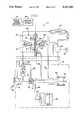
- FIG. 1is a simplified schematic diagram of the integral anti-lock brake system control actuator assembly of the present invention
- FIG. 2is a simplified schematic diagram of a portion of the integral antilock brake control and traction control system.
- FIG. 3is a simplified schematic of a portion of the means for modulating the pressure of the brake fluid in the system.
- the present inventionrelates to an integral anti-lock brake and traction control system for a vehicle. While described with reference to a single wheel and brake cylinder for simplicity, it will be apparent to those skilled in the art that the system of the present invention is applicable for use in wheeled vehicles having driven pairs of wheels joined through a common axle.
- a pressure control valvewhich includes a pair of pressure feedback valves, regulates brake pressure applied to the wheels of the vehicle.
- a linear motoracts on the pressure feedback valves to provide a brake control pressure proportionally related to the voltage applied to the linear motor.
- the integral systemis indicated generally by reference numeral 10 and comprises an anti-lock braking control system (ABS) 12 and traction control system 14 for a vehicle as illustrated.
- ABSanti-lock braking control system
- traction control system 14for a vehicle as illustrated.
- the two systemsinclude a master cylinder 16 containing brake fluid for operation, a double check valve 18, and a wheel brake cylinder 20 operated by an input means which is preferably a foot-operated vehicle brake pedal 22.
- the brake cylinder 20 and brake pedal 22communicate with a means 23 for vehicle braking, for example a disk brake mechanism.
- the integral system 10also includes a sump 28 which operates as a reservoir for vehicle brake fluid.
- the system 10includes a pump 30 and associated motor 32 for generating fluid power and pressurizing the brake fluid.
- Accumulator 34is a source of brake fluid under pressure and functions to store the fluid at high pressure.
- a wheel speed sensor 41in conjunction with a control module 46 determines wheel speed relative to the speed of the vehicle. The control module 46 then activates a moving coil linear motor 44 by the application of an analog or pulse width modulated voltage to control braking or traction as explained in greater detail below.
- Pressure control valve 26includes a first pressure feedback valve 24 and a second pressure feedback valve 24'. Control valve 26 regulates the brake pressure in the vehicle and controls both braking and traction for the vehicle.
- a linear motor 44acts on pressure control valve 26 to provide brake fluid pressure which is proportional to the voltage applied to coils 42 of linear motor 44. Linear motor 44 includes two stationary magnets 39 and respective moving coils 42.
- a flapper or hinge valve 48adjusts the pressure in pressure control valve 26 until the pressure in flapper 48 is equalized by the force of linear motor 44.
- brake fluidpasses from the master cylinder 16 past a first poppet valve portion 56 of double check valve 18 and past a second poppet portion 57 which is held open by piston member 54, to wheel brake cylinder 20, via a wheel brake cylinder port 36.
- a traction control lockout valve 38is lifted by the brake fluid pressure to close passage 40 to the traction control system 14 portion of the integral system 10, thereby isolating the traction control system 14 such that integral system 10 operates only in the braking control mode.
- control module 46activates pressure control valve 26 by causing a dc voltage to be applied to coils 42 of linear motor 44 to shift pressure control valve 26 to a position which admits brake fluid to a chamber 50.
- this movementis depicted as being to the right in the drawings.
- all references in the drawings to a directioni.e., left, right, up, or down
- a flapper 48moves first pressure feedback valve 24 to the right, admitting fluid pressure to chamber 50, and simultaneously to an anti-lock brake system (ABS) actuator 52, through fluid conduit 53, and back against flapper 48. Pressure rises in the anti-lock brake system actuator 52 until the pressure force against flapper 48 is equalized by voltage (force) applied to linear motor 44.
- voltageforce
- pressure in antilock brake system 12is proportional to the signal voltage, either analog or pulse width modulated voltage, applied to the linear motor 44.
- a piston 54 in the anti-lock brake system actuator 52is displaced to the right by the pressure of the brake fluid, thereby allowing second poppet portion 57 of double check valve 18 to close.
- control module 46reduces the voltage applied to the coils 42.
- control module 46again increases the voltage applied to coils 42 to reduce the pressure in the brake cylinder 20 as previously described.
- control module 46continues to reduce the voltage on coils 42 until piston 54 unseats second poppet portion 57 in double check valve 18 and direct, manual control of the brake is restored.
- the integral ABS and traction control actuator assembly 10operates as a traction control system when a wheel spins faster than its synchronous speed with the vehicle in the accelerating direction. This is a condition which commonly occurs when one driving wheel of a pair is located on a poorer tractive road surface than the other.
- Traction control system 14includes second pressure feedback valve 24' which admits fluid under pressure to chamber 50' when second pressure feedback valve 24' is shifted to the left by the action of linear motor 44 and coils 42. Pressure proportional to the voltage applied to linear motor 44 by control module 46 is applied to wheel brake cylinder 20 to control the wheel rotation speed sensed by the wheel speed sensor 41.
- the brake fluid under pressurepasses through fluid passage 40, double check valve 18, and cylinder port 36 to apply fluid pressure to brake cylinder 20.
- Thisdevelops a reactive wheel torque which enables the second wheel of an axle pair to develop a larger driving torque with the road surface.
- a poppet valve 56 in the double check valve 18isolates the master cylinder 16 so that brake fluid under pressure is not circulated to the master cylinder in this mode.
- first pressure feedback valve 24is shown as a portion of a pressure modulator 58 which is responsive to the braking control system 12 and the traction control system 14 for integrally controlling vehicle braking and traction.
- the diameter of bore 60, the touch diameter of metering seat 62, and bellows neutral force diameter 64,are all equal to the same diameter, d.
- first pressure feedback valve 24is shifted to admit fluid into chamber 50 from a pressure inlet port 68.
- the chamber 50is connected to outlet port 70 and flapper 48 through aperture 72.
Landscapes
- Physics & Mathematics (AREA)
- Engineering & Computer Science (AREA)
- Fluid Mechanics (AREA)
- Transportation (AREA)
- Mechanical Engineering (AREA)
- Electromagnetism (AREA)
- Regulating Braking Force (AREA)
Abstract
Description
The present invention relates to an integral anti-lock brake and traction control system, and, more particularly, to a system which is operable in a first mode as an anti-lock brake control system and in a second mode as a traction control system. Conventional systems for preventing a wheel of a motor vehicle from locking during braking or from spinning from loss of traction are known. One such braking system is a system which controls brake fluid pressure applied to a wheel cylinder of a brake device based on a rotation status of the wheel relative, to a threshold value when the brake is operated. Another system prevents a driving wheel of a vehicle from slipping by controlling a brake force caused by a brake fluid pressure in a wheel cylinder of a brake device of the driving wheel based on a slipping status relative to a threshold value when the vehicle starts to move and accelerates.
These conventional systems have a problem in that they tend to be complicated, large-sized and, therefore, expensive. In addition, prior systems have slow response time. Although some problems may be alleviated by integrating the anti-lock brake control system and the traction control system of a vehicle, previous attempts at such integration have added both complications and costs.
Accordingly, there remains a need for an integrated brake and traction control system which provides a fast response time and is economical.
The present invention meets this need by providing an electro-hydro-mechanical integrated anti-lock brake and traction control assembly wherein a linear motor acts on a pressure control valve to provide brake pressure proportional to the voltage signal supplied to the motor. The mode of operation, either anti-lock brake system control or traction control, is selected by simply changing the polarity on the linear motor.
In accordance with one aspect of the present invention an integral anti-lock brake and traction control system for a vehicle is provided which includes a pressure control valve including a first pressure feedback valve associated with a braking control system and a second pressure feedback valve associated with a traction control system. In a first mode, means responsive to a control voltage, such as a linear motor, are provided which activate the first pressure feedback valve to regulate brake pressure in the braking control system proportionally to the control voltage which is supplied. In a second mode, the means responsive to the control voltage activates the second pressure feedback valve to control vehicle traction in the traction control system. The modes are selected by simply changing the polarity of the control voltage signal.
In another embodiment of the invention, an integral anti-lock brake and traction control system for a wheeled vehicle is provided and includes a braking control system and a traction control system cooperating with the braking control system for controlling the rotational speed of the vehicle wheels. The braking control system comprises braking means operatively associated with the vehicle wheels for retarding the rotation of the wheels. The braking means include a brake cylinder and a source of brake fluid under pressure. The integral system also includes means for sensing the speed of the wheels relative to the synchronous speed of the vehicle and generating a control voltage responsive thereto. By synchronous speed, it is meant that the rotational speed of the wheels match the linear speed of the vehicle. To control vehicle braking and traction integrally, means responsive to the control voltage, such as a pressure control valve, are provided for modulating the pressure of the brake fluid in the brake cylinder.
An advantage of the present invention is that the traction control mode and the anti-lock brake system control mode of the wheel brakes are separate, without one imposing a performance limitation on the other, and a failure in any part of the control system does not impair the manually operated, foundation brakes. The anti-lock brake system and traction control modes are selected by changing the polarity on a linear motor. The linear motor acting on the pressure feedback valve is utilized to provide a brake pressure proportional or inversely proportional to an analog or pulse modulated voltage.
Accordingly, it is an object of the present invention to provide an integrated brake and traction control system which provides a fast response time and is economical. Other objects and advantages of the invention will be apparent from the following detailed description, the accompanying drawings, and the appended claims.
FIG. 1 is a simplified schematic diagram of the integral anti-lock brake system control actuator assembly of the present invention;
FIG. 2 is a simplified schematic diagram of a portion of the integral antilock brake control and traction control system; and
FIG. 3 is a simplified schematic of a portion of the means for modulating the pressure of the brake fluid in the system.
The present invention relates to an integral anti-lock brake and traction control system for a vehicle. While described with reference to a single wheel and brake cylinder for simplicity, it will be apparent to those skilled in the art that the system of the present invention is applicable for use in wheeled vehicles having driven pairs of wheels joined through a common axle. A pressure control valve which includes a pair of pressure feedback valves, regulates brake pressure applied to the wheels of the vehicle. A linear motor acts on the pressure feedback valves to provide a brake control pressure proportionally related to the voltage applied to the linear motor.
Referring now to FIG. 1, the integral system is indicated generally byreference numeral 10 and comprises an anti-lock braking control system (ABS) 12 andtraction control system 14 for a vehicle as illustrated. These two systems operate separately and independently in that neither imposes a performance limitation on the other. However, the twosystems
For example, the two systems include amaster cylinder 16 containing brake fluid for operation, adouble check valve 18, and awheel brake cylinder 20 operated by an input means which is preferably a foot-operatedvehicle brake pedal 22. Thebrake cylinder 20 andbrake pedal 22 communicate with ameans 23 for vehicle braking, for example a disk brake mechanism. Theintegral system 10 also includes asump 28 which operates as a reservoir for vehicle brake fluid. In addition, thesystem 10 includes apump 30 and associatedmotor 32 for generating fluid power and pressurizing the brake fluid. Accumulator 34 is a source of brake fluid under pressure and functions to store the fluid at high pressure. Finally, awheel speed sensor 41 in conjunction with acontrol module 46 determines wheel speed relative to the speed of the vehicle. Thecontrol module 46 then activates a moving coillinear motor 44 by the application of an analog or pulse width modulated voltage to control braking or traction as explained in greater detail below.
Referring now to FIG. 2, additional elements of thebraking control system 12 andtraction control system 14 are illustrated.Pressure control valve 26 includes a firstpressure feedback valve 24 and a second pressure feedback valve 24'.Control valve 26 regulates the brake pressure in the vehicle and controls both braking and traction for the vehicle. Alinear motor 44 acts onpressure control valve 26 to provide brake fluid pressure which is proportional to the voltage applied tocoils 42 oflinear motor 44.Linear motor 44 includes twostationary magnets 39 and respectivemoving coils 42. A flapper orhinge valve 48 adjusts the pressure inpressure control valve 26 until the pressure inflapper 48 is equalized by the force oflinear motor 44.
Referring back to FIG. 1, when the integral braking andtraction control system 10 is operating in a braking control mode, brake fluid passes from themaster cylinder 16 past a firstpoppet valve portion 56 ofdouble check valve 18 and past asecond poppet portion 57 which is held open bypiston member 54, towheel brake cylinder 20, via a wheelbrake cylinder port 36. A tractioncontrol lockout valve 38 is lifted by the brake fluid pressure to closepassage 40 to thetraction control system 14 portion of theintegral system 10, thereby isolating thetraction control system 14 such thatintegral system 10 operates only in the braking control mode.
When excessive force is applied by an operator to thebrake pedal 22 causing the braked road wheel to approach lock-up as sensed by awheel speed sensor 41,control module 46 activatespressure control valve 26 by causing a dc voltage to be applied tocoils 42 oflinear motor 44 to shiftpressure control valve 26 to a position which admits brake fluid to achamber 50. For illustrative purposes, this movement is depicted as being to the right in the drawings. However, all references in the drawings to a direction (i.e., left, right, up, or down) are for convenience only in understanding the invention as drawn. No limitation is intended to the scope of the invention.
Aflapper 48 moves firstpressure feedback valve 24 to the right, admitting fluid pressure tochamber 50, and simultaneously to an anti-lock brake system (ABS)actuator 52, throughfluid conduit 53, and back againstflapper 48. Pressure rises in the anti-lockbrake system actuator 52 until the pressure force againstflapper 48 is equalized by voltage (force) applied tolinear motor 44. Thus, pressure inantilock brake system 12 is proportional to the signal voltage, either analog or pulse width modulated voltage, applied to thelinear motor 44.
Apiston 54 in the anti-lockbrake system actuator 52 is displaced to the right by the pressure of the brake fluid, thereby allowingsecond poppet portion 57 ofdouble check valve 18 to close. Thisisolates brake cylinder 20 from the brake fluid supply and allows the pressure inbrake cylinder 20, and consequently the braking effort, to drop until wheel spin up of the vehicle occurs. When the wheel spins up, as sensed by thewheel speed sensor 41, and approaches but does not equal the synchronous speed with the vehicle,control module 46 reduces the voltage applied to thecoils 42. This acts to reduce the pressure in thebrake system actuator 52 so that the excess force of cagedspring 55 over that of the opposing pressure force of the fluid urgespiston 54 to the left, reopeningsecond poppet portion 57 ofdouble check valve 18 and exposingbrake cylinder 20 to additional brake fluid pressure. This increases the braking force applied to the wheel. When the braked road wheel spins down approaching lock as sensed bywheel speed sensor 41,control module 46 again increases the voltage applied tocoils 42 to reduce the pressure in thebrake cylinder 20 as previously described. If movement of thepiston 54 to the left does not cause the braked road wheel to spin down as sensed bywheel speed sensor 41,control module 46 continues to reduce the voltage oncoils 42 untilpiston 54 unseatssecond poppet portion 57 indouble check valve 18 and direct, manual control of the brake is restored.
Continuing with reference to FIG. 1, the integral ABS and tractioncontrol actuator assembly 10 operates as a traction control system when a wheel spins faster than its synchronous speed with the vehicle in the accelerating direction. This is a condition which commonly occurs when one driving wheel of a pair is located on a poorer tractive road surface than the other.Traction control system 14 includes second pressure feedback valve 24' which admits fluid under pressure to chamber 50' when second pressure feedback valve 24' is shifted to the left by the action oflinear motor 44 and coils 42. Pressure proportional to the voltage applied tolinear motor 44 bycontrol module 46 is applied towheel brake cylinder 20 to control the wheel rotation speed sensed by thewheel speed sensor 41. From chamber 50', the brake fluid under pressure passes throughfluid passage 40,double check valve 18, andcylinder port 36 to apply fluid pressure to brakecylinder 20. This develops a reactive wheel torque which enables the second wheel of an axle pair to develop a larger driving torque with the road surface. Apoppet valve 56 in thedouble check valve 18 isolates themaster cylinder 16 so that brake fluid under pressure is not circulated to the master cylinder in this mode.
Referring now to FIG. 3, firstpressure feedback valve 24 is shown as a portion of apressure modulator 58 which is responsive to thebraking control system 12 and thetraction control system 14 for integrally controlling vehicle braking and traction. The diameter ofbore 60, the touch diameter ofmetering seat 62, and bellowsneutral force diameter 64, are all equal to the same diameter, d. When a force is applied to the right byflapper 48 againstflapper seat 66, firstpressure feedback valve 24 is shifted to admit fluid intochamber 50 from apressure inlet port 68. Thechamber 50 is connected tooutlet port 70 andflapper 48 throughaperture 72.
The fluid pressure force in the axial chamber connecting to port 70 acting againstflapper 48 shifts theflapper 48 to the left, allowing thepressure feedback valve 24 to shift to the left, closingmetering seat 62 until a force equilibrium is obtained between the force acting onflapper 48 and the pressure inchamber 50. Hence, pressure at outlet port 70 (which in turn communicates withABS actuator 52 through fluid conduit 53) is proportional to the force onflapper 48. This pressure, in turn, is proportional to the signal voltage applied tolinear motor 44. This pressure modulator construction obviates the need to measure the pressure and to control the linear force motor through more complex means.
Having described the invention in detail and by way of reference to preferred embodiments thereof, it will be apparent that modifications and variations are possible without departing from the scope of the invention which is defined in the appended claims.
Claims (9)
1. An integral anti-lock brake and traction control system for a vehicle comprising:
a pressure control valve including a flapper valve, a first pressure feedback valve associated with a braking control system, and a second pressure feedback valve associated with a traction control system; and
means responsive to a control voltage for activating said flapper valve to open either said first pressure feedback valve to regulate brake pressure in said braking control system proportionally to said voltage in a first mode, or said second pressure feedback valve to control vehicle traction in said traction control system in a second mode, wherein said first pressure feedback valve and said second pressure feedback valve are movable in response to direct force applied by said flapper valve.
2. An integral anti-lock brake and traction control system as claimed in claim 1 in which said means responsive to said control voltage comprises a linear motor.
3. An integral anti-lock brake and traction control system as claimed in claim 1 including means for sensing the speed of at least one wheel of said vehicle and means for generating a control voltage responsive to said sensing means.
4. An integral anti-lock brake and traction control system as claimed in claim 3 in which said anti-lock brake and traction control system is changed from said first mode to said second mode by changing the polarity of said control voltage.
5. An integral anti-lock brake and traction control system for a wheeled vehicle comprising:
a braking control system comprising braking means operatively associated wit the vehicle wheels for retarding the rotation of said wheels, said braking means including a brake cylinder and a source of brake fluid under pressure, a traction control system cooperating with said braking control system for controlling the rotational speed of said vehicle wheels;
means for sensing the speed of said wheels relative to the synchronous speed of said vehicle and generating a control voltage responsive thereto; and
means responsive to said control voltage for modulating the pressure of said brake fluid in said brake cylinder to integrally control vehicle braking and traction, said means including a pressure control valve, said pressure control valve including a flapper valve between two opposing pressure feedback valves, with said feedback valves being movable in response to direct force applied by said flapper valve.
6. The integral anti-lock brake and traction control system of claim 5 wherein said pressure control valve comprises a first pressure feedback valve associated with a braking control system and a second pressure feedback valve associated with a traction control system.
7. The integral anti-lock brake and traction control system of claim 6 wherein said means responsive to said control voltage comprises a linear motor.
8. The integral anti-lock brake and traction control system of claim 7 wherein said linear motor moves a centrally-located flapper in a first direction to activate said braking control system and in a second direction to activate said traction control system.
9. The integral anti-lock brake and traction control system of claim 5 wherein said braking control system further includes a braking control actuator responsive to said means for modulating the pressure of said brake fluid, said braking control actuator comprising a spring-biased piston and check valve for isolating said brake cylinder.
Priority Applications (1)
| Application Number | Priority Date | Filing Date | Title |
|---|---|---|---|
| US07/765,613US5217283A (en) | 1991-09-25 | 1991-09-25 | Integral anti-lock brake/traction control system |
Applications Claiming Priority (1)
| Application Number | Priority Date | Filing Date | Title |
|---|---|---|---|
| US07/765,613US5217283A (en) | 1991-09-25 | 1991-09-25 | Integral anti-lock brake/traction control system |
Publications (1)
| Publication Number | Publication Date |
|---|---|
| US5217283Atrue US5217283A (en) | 1993-06-08 |
Family
ID=25074008
Family Applications (1)
| Application Number | Title | Priority Date | Filing Date |
|---|---|---|---|
| US07/765,613Expired - Fee RelatedUS5217283A (en) | 1991-09-25 | 1991-09-25 | Integral anti-lock brake/traction control system |
Country Status (1)
| Country | Link |
|---|---|
| US (1) | US5217283A (en) |
Cited By (40)
| Publication number | Priority date | Publication date | Assignee | Title |
|---|---|---|---|---|
| WO1995015873A1 (en)* | 1993-12-06 | 1995-06-15 | Ford Motor Company | Piezoelectric fluid control valve |
| US5458406A (en)* | 1994-01-14 | 1995-10-17 | Itt Corporation | Electronic pressure relief system for traction control |
| US6019437A (en)* | 1996-05-29 | 2000-02-01 | Kelsey-Hayes Company | Vehicle hydraulic braking systems incorporating micro-machined technology |
| US6209966B1 (en)* | 1997-03-05 | 2001-04-03 | Mannesmann Rexroth Ag | Electrically controlled braking system for a wheeled vehicle |
| US6494804B1 (en) | 2000-06-20 | 2002-12-17 | Kelsey-Hayes Company | Microvalve for electronically controlled transmission |
| US6505811B1 (en) | 2000-06-27 | 2003-01-14 | Kelsey-Hayes Company | High-pressure fluid control valve assembly having a microvalve device attached to fluid distributing substrate |
| US6523560B1 (en) | 1998-09-03 | 2003-02-25 | General Electric Corporation | Microvalve with pressure equalization |
| US6533366B1 (en)* | 1996-05-29 | 2003-03-18 | Kelsey-Hayes Company | Vehicle hydraulic braking systems incorporating micro-machined technology |
| US6540203B1 (en) | 1999-03-22 | 2003-04-01 | Kelsey-Hayes Company | Pilot operated microvalve device |
| US6581640B1 (en) | 2000-08-16 | 2003-06-24 | Kelsey-Hayes Company | Laminated manifold for microvalve |
| US6694998B1 (en) | 2000-03-22 | 2004-02-24 | Kelsey-Hayes Company | Micromachined structure usable in pressure regulating microvalve and proportional microvalve |
| US6761420B2 (en) | 1998-09-03 | 2004-07-13 | Ge Novasensor | Proportional micromechanical device |
| US6845962B1 (en) | 2000-03-22 | 2005-01-25 | Kelsey-Hayes Company | Thermally actuated microvalve device |
| US20050156129A1 (en)* | 1998-09-03 | 2005-07-21 | General Electric Company | Proportional micromechanical valve |
| US20060022160A1 (en)* | 2004-07-27 | 2006-02-02 | Fuller Edward N | Method of controlling microvalve actuator |
| US20070172362A1 (en)* | 2003-11-24 | 2007-07-26 | Fuller Edward N | Microvalve device suitable for controlling a variable displacement compressor |
| US20070251586A1 (en)* | 2003-11-24 | 2007-11-01 | Fuller Edward N | Electro-pneumatic control valve with microvalve pilot |
| US20070289941A1 (en)* | 2004-03-05 | 2007-12-20 | Davies Brady R | Selective Bonding for Forming a Microvalve |
| US20080042084A1 (en)* | 2004-02-27 | 2008-02-21 | Edward Nelson Fuller | Hybrid Micro/Macro Plate Valve |
| US20080047622A1 (en)* | 2003-11-24 | 2008-02-28 | Fuller Edward N | Thermally actuated microvalve with multiple fluid ports |
| US20090123300A1 (en)* | 2005-01-14 | 2009-05-14 | Alumina Micro Llc | System and method for controlling a variable displacement compressor |
| US20090173387A1 (en)* | 2007-11-01 | 2009-07-09 | Honeywell International Inc. | Piezoelectric actuator with a gimballed valve |
| US20100019177A1 (en)* | 2006-12-15 | 2010-01-28 | Luckevich Mark S | Microvalve device |
| US20100326530A1 (en)* | 2007-11-01 | 2010-12-30 | Honeywell International, Inc. | Piezoelectric flow control valve |
| US20110127455A1 (en)* | 2008-08-09 | 2011-06-02 | Microstaq, Inc. | Improved Microvalve Device |
| US8113482B2 (en) | 2008-08-12 | 2012-02-14 | DunAn Microstaq | Microvalve device with improved fluid routing |
| US8387659B2 (en) | 2007-03-31 | 2013-03-05 | Dunan Microstaq, Inc. | Pilot operated spool valve |
| US8393344B2 (en) | 2007-03-30 | 2013-03-12 | Dunan Microstaq, Inc. | Microvalve device with pilot operated spool valve and pilot microvalve |
| US8540207B2 (en) | 2008-12-06 | 2013-09-24 | Dunan Microstaq, Inc. | Fluid flow control assembly |
| US8593811B2 (en) | 2009-04-05 | 2013-11-26 | Dunan Microstaq, Inc. | Method and structure for optimizing heat exchanger performance |
| US8925793B2 (en) | 2012-01-05 | 2015-01-06 | Dunan Microstaq, Inc. | Method for making a solder joint |
| US8956884B2 (en) | 2010-01-28 | 2015-02-17 | Dunan Microstaq, Inc. | Process for reconditioning semiconductor surface to facilitate bonding |
| US8996141B1 (en) | 2010-08-26 | 2015-03-31 | Dunan Microstaq, Inc. | Adaptive predictive functional controller |
| US9006844B2 (en) | 2010-01-28 | 2015-04-14 | Dunan Microstaq, Inc. | Process and structure for high temperature selective fusion bonding |
| US9140613B2 (en) | 2012-03-16 | 2015-09-22 | Zhejiang Dunan Hetian Metal Co., Ltd. | Superheat sensor |
| US9188375B2 (en) | 2013-12-04 | 2015-11-17 | Zhejiang Dunan Hetian Metal Co., Ltd. | Control element and check valve assembly |
| US9702481B2 (en) | 2009-08-17 | 2017-07-11 | Dunan Microstaq, Inc. | Pilot-operated spool valve |
| US11078839B2 (en) | 2018-01-22 | 2021-08-03 | Rolls-Royce Corporation | Composite nosecone |
| US11421538B2 (en) | 2020-05-12 | 2022-08-23 | Rolls-Royce Corporation | Composite aerofoils |
| US11506083B2 (en) | 2020-06-03 | 2022-11-22 | Rolls-Royce Corporalion | Composite liners for turbofan engines |
Citations (22)
| Publication number | Priority date | Publication date | Assignee | Title |
|---|---|---|---|---|
| US3845992A (en)* | 1972-03-14 | 1974-11-05 | Aisin Seiki | Hydraulic pressure control apparatus |
| US3874742A (en)* | 1972-09-27 | 1975-04-01 | Aisin Seiki | Hydraulic brake pressure control system |
| US4032197A (en)* | 1976-05-04 | 1977-06-28 | Abex Corporation | Slip/slide detector control circuit |
| US4156547A (en)* | 1977-08-23 | 1979-05-29 | Aspro, Inc. | Speed-responsive anti-skid and anti-spin system for vehicles |
| US4310201A (en)* | 1979-12-07 | 1982-01-12 | The Bendix Corporation | Adaptive traction pressure regulator |
| US4565411A (en)* | 1983-07-29 | 1986-01-21 | Itt Industries, Inc. | Hydraulic brake system with slip control |
| US4583611A (en)* | 1983-08-31 | 1986-04-22 | Robert Bosch Gmbh | Wheel spin prevention system |
| US4641895A (en)* | 1983-10-26 | 1987-02-10 | Itt Industries Inc. | Brake system with slip control for automotive vehicles |
| US4643485A (en)* | 1984-02-06 | 1987-02-17 | Robert Bosch Gmbh | Vehicle brake system including means for reducing drive slip |
| US4743075A (en)* | 1984-10-19 | 1988-05-10 | Alfred Teves Gmbh | Combined traction slip- and slip-controlled brake system |
| US4755008A (en)* | 1985-12-25 | 1988-07-05 | Nippondenso Co., Ltd. | Braking system with power brake, braking force proportioning, anti-skid, and traction control functions |
| US4765691A (en)* | 1986-01-21 | 1988-08-23 | Toyota Jidosha Kabushiki Kaisha | Wheel slip control system |
| US4778224A (en)* | 1987-01-13 | 1988-10-18 | Daimler-Benz Aktiengesellschaft | Brake unit with brake booster, two master cylinders for antilock and/or propulsion or slip control situated in common housing including pivotable rocker |
| US4794538A (en)* | 1985-10-08 | 1988-12-27 | Robert Bosch Gmbh | Method to control the operation of wheels of a vehicle to prevent slipping or skidding, and brake locking |
| US4802562A (en)* | 1986-03-17 | 1989-02-07 | Nippondenso Co., Ltd. | Electronically controlled braking system without a master cylinder |
| US4807943A (en)* | 1986-12-16 | 1989-02-28 | Akebono Brake Industry Co., Ltd. | Brake control system for a motor vehicle |
| US4818039A (en)* | 1986-10-03 | 1989-04-04 | Robert Bosch Gmbh | Automatic drive slip regulating unit |
| US4838622A (en)* | 1987-05-22 | 1989-06-13 | Alfred Teves Gmbh | Brake system with anti-lock control and/or traction slip control as well as braking pressure modulator for such a brake system |
| US4950028A (en)* | 1987-11-20 | 1990-08-21 | Lucas Industries Public Limited Company | Hydraulic braking system |
| US5029950A (en)* | 1989-06-26 | 1991-07-09 | General Motors Corporation | Anti-lock braking and traction control system |
| US5042885A (en)* | 1989-11-16 | 1991-08-27 | General Motors Corporation | Integrated anti-lock braking and traction control system |
| US5102206A (en)* | 1989-06-26 | 1992-04-07 | General Motors Corporation | Anti-lock braking and traction control system |
- 1991
- 1991-09-25USUS07/765,613patent/US5217283A/ennot_activeExpired - Fee Related
Patent Citations (22)
| Publication number | Priority date | Publication date | Assignee | Title |
|---|---|---|---|---|
| US3845992A (en)* | 1972-03-14 | 1974-11-05 | Aisin Seiki | Hydraulic pressure control apparatus |
| US3874742A (en)* | 1972-09-27 | 1975-04-01 | Aisin Seiki | Hydraulic brake pressure control system |
| US4032197A (en)* | 1976-05-04 | 1977-06-28 | Abex Corporation | Slip/slide detector control circuit |
| US4156547A (en)* | 1977-08-23 | 1979-05-29 | Aspro, Inc. | Speed-responsive anti-skid and anti-spin system for vehicles |
| US4310201A (en)* | 1979-12-07 | 1982-01-12 | The Bendix Corporation | Adaptive traction pressure regulator |
| US4565411A (en)* | 1983-07-29 | 1986-01-21 | Itt Industries, Inc. | Hydraulic brake system with slip control |
| US4583611A (en)* | 1983-08-31 | 1986-04-22 | Robert Bosch Gmbh | Wheel spin prevention system |
| US4641895A (en)* | 1983-10-26 | 1987-02-10 | Itt Industries Inc. | Brake system with slip control for automotive vehicles |
| US4643485A (en)* | 1984-02-06 | 1987-02-17 | Robert Bosch Gmbh | Vehicle brake system including means for reducing drive slip |
| US4743075A (en)* | 1984-10-19 | 1988-05-10 | Alfred Teves Gmbh | Combined traction slip- and slip-controlled brake system |
| US4794538A (en)* | 1985-10-08 | 1988-12-27 | Robert Bosch Gmbh | Method to control the operation of wheels of a vehicle to prevent slipping or skidding, and brake locking |
| US4755008A (en)* | 1985-12-25 | 1988-07-05 | Nippondenso Co., Ltd. | Braking system with power brake, braking force proportioning, anti-skid, and traction control functions |
| US4765691A (en)* | 1986-01-21 | 1988-08-23 | Toyota Jidosha Kabushiki Kaisha | Wheel slip control system |
| US4802562A (en)* | 1986-03-17 | 1989-02-07 | Nippondenso Co., Ltd. | Electronically controlled braking system without a master cylinder |
| US4818039A (en)* | 1986-10-03 | 1989-04-04 | Robert Bosch Gmbh | Automatic drive slip regulating unit |
| US4807943A (en)* | 1986-12-16 | 1989-02-28 | Akebono Brake Industry Co., Ltd. | Brake control system for a motor vehicle |
| US4778224A (en)* | 1987-01-13 | 1988-10-18 | Daimler-Benz Aktiengesellschaft | Brake unit with brake booster, two master cylinders for antilock and/or propulsion or slip control situated in common housing including pivotable rocker |
| US4838622A (en)* | 1987-05-22 | 1989-06-13 | Alfred Teves Gmbh | Brake system with anti-lock control and/or traction slip control as well as braking pressure modulator for such a brake system |
| US4950028A (en)* | 1987-11-20 | 1990-08-21 | Lucas Industries Public Limited Company | Hydraulic braking system |
| US5029950A (en)* | 1989-06-26 | 1991-07-09 | General Motors Corporation | Anti-lock braking and traction control system |
| US5102206A (en)* | 1989-06-26 | 1992-04-07 | General Motors Corporation | Anti-lock braking and traction control system |
| US5042885A (en)* | 1989-11-16 | 1991-08-27 | General Motors Corporation | Integrated anti-lock braking and traction control system |
Cited By (52)
| Publication number | Priority date | Publication date | Assignee | Title |
|---|---|---|---|---|
| WO1995015873A1 (en)* | 1993-12-06 | 1995-06-15 | Ford Motor Company | Piezoelectric fluid control valve |
| US5458406A (en)* | 1994-01-14 | 1995-10-17 | Itt Corporation | Electronic pressure relief system for traction control |
| US6533366B1 (en)* | 1996-05-29 | 2003-03-18 | Kelsey-Hayes Company | Vehicle hydraulic braking systems incorporating micro-machined technology |
| US6019437A (en)* | 1996-05-29 | 2000-02-01 | Kelsey-Hayes Company | Vehicle hydraulic braking systems incorporating micro-machined technology |
| US6209966B1 (en)* | 1997-03-05 | 2001-04-03 | Mannesmann Rexroth Ag | Electrically controlled braking system for a wheeled vehicle |
| US20050156129A1 (en)* | 1998-09-03 | 2005-07-21 | General Electric Company | Proportional micromechanical valve |
| US6761420B2 (en) | 1998-09-03 | 2004-07-13 | Ge Novasensor | Proportional micromechanical device |
| US7367359B2 (en) | 1998-09-03 | 2008-05-06 | Kelsey-Hayes Company | Proportional micromechanical valve |
| US7011378B2 (en) | 1998-09-03 | 2006-03-14 | Ge Novasensor, Inc. | Proportional micromechanical valve |
| US6523560B1 (en) | 1998-09-03 | 2003-02-25 | General Electric Corporation | Microvalve with pressure equalization |
| US6540203B1 (en) | 1999-03-22 | 2003-04-01 | Kelsey-Hayes Company | Pilot operated microvalve device |
| US6994115B2 (en) | 2000-03-22 | 2006-02-07 | Kelsey-Hayes Company | Thermally actuated microvalve device |
| US6694998B1 (en) | 2000-03-22 | 2004-02-24 | Kelsey-Hayes Company | Micromachined structure usable in pressure regulating microvalve and proportional microvalve |
| US20050121090A1 (en)* | 2000-03-22 | 2005-06-09 | Hunnicutt Harry A. | Thermally actuated microvalve device |
| US6845962B1 (en) | 2000-03-22 | 2005-01-25 | Kelsey-Hayes Company | Thermally actuated microvalve device |
| US6494804B1 (en) | 2000-06-20 | 2002-12-17 | Kelsey-Hayes Company | Microvalve for electronically controlled transmission |
| US6505811B1 (en) | 2000-06-27 | 2003-01-14 | Kelsey-Hayes Company | High-pressure fluid control valve assembly having a microvalve device attached to fluid distributing substrate |
| US6581640B1 (en) | 2000-08-16 | 2003-06-24 | Kelsey-Hayes Company | Laminated manifold for microvalve |
| US20070172362A1 (en)* | 2003-11-24 | 2007-07-26 | Fuller Edward N | Microvalve device suitable for controlling a variable displacement compressor |
| US20070251586A1 (en)* | 2003-11-24 | 2007-11-01 | Fuller Edward N | Electro-pneumatic control valve with microvalve pilot |
| US20080047622A1 (en)* | 2003-11-24 | 2008-02-28 | Fuller Edward N | Thermally actuated microvalve with multiple fluid ports |
| US8011388B2 (en) | 2003-11-24 | 2011-09-06 | Microstaq, INC | Thermally actuated microvalve with multiple fluid ports |
| US20080042084A1 (en)* | 2004-02-27 | 2008-02-21 | Edward Nelson Fuller | Hybrid Micro/Macro Plate Valve |
| US20070289941A1 (en)* | 2004-03-05 | 2007-12-20 | Davies Brady R | Selective Bonding for Forming a Microvalve |
| US7803281B2 (en) | 2004-03-05 | 2010-09-28 | Microstaq, Inc. | Selective bonding for forming a microvalve |
| US7156365B2 (en) | 2004-07-27 | 2007-01-02 | Kelsey-Hayes Company | Method of controlling microvalve actuator |
| US20060022160A1 (en)* | 2004-07-27 | 2006-02-02 | Fuller Edward N | Method of controlling microvalve actuator |
| US20090123300A1 (en)* | 2005-01-14 | 2009-05-14 | Alumina Micro Llc | System and method for controlling a variable displacement compressor |
| US20100019177A1 (en)* | 2006-12-15 | 2010-01-28 | Luckevich Mark S | Microvalve device |
| US8156962B2 (en) | 2006-12-15 | 2012-04-17 | Dunan Microstaq, Inc. | Microvalve device |
| US8393344B2 (en) | 2007-03-30 | 2013-03-12 | Dunan Microstaq, Inc. | Microvalve device with pilot operated spool valve and pilot microvalve |
| US8387659B2 (en) | 2007-03-31 | 2013-03-05 | Dunan Microstaq, Inc. | Pilot operated spool valve |
| US20100326530A1 (en)* | 2007-11-01 | 2010-12-30 | Honeywell International, Inc. | Piezoelectric flow control valve |
| US7841579B2 (en) | 2007-11-01 | 2010-11-30 | Honeywell International Inc. | Piezoelectric actuator with a gimballed valve |
| US20090173387A1 (en)* | 2007-11-01 | 2009-07-09 | Honeywell International Inc. | Piezoelectric actuator with a gimballed valve |
| US8662468B2 (en) | 2008-08-09 | 2014-03-04 | Dunan Microstaq, Inc. | Microvalve device |
| US20110127455A1 (en)* | 2008-08-09 | 2011-06-02 | Microstaq, Inc. | Improved Microvalve Device |
| US8113482B2 (en) | 2008-08-12 | 2012-02-14 | DunAn Microstaq | Microvalve device with improved fluid routing |
| US8540207B2 (en) | 2008-12-06 | 2013-09-24 | Dunan Microstaq, Inc. | Fluid flow control assembly |
| US8593811B2 (en) | 2009-04-05 | 2013-11-26 | Dunan Microstaq, Inc. | Method and structure for optimizing heat exchanger performance |
| US9702481B2 (en) | 2009-08-17 | 2017-07-11 | Dunan Microstaq, Inc. | Pilot-operated spool valve |
| US8956884B2 (en) | 2010-01-28 | 2015-02-17 | Dunan Microstaq, Inc. | Process for reconditioning semiconductor surface to facilitate bonding |
| US9006844B2 (en) | 2010-01-28 | 2015-04-14 | Dunan Microstaq, Inc. | Process and structure for high temperature selective fusion bonding |
| US8996141B1 (en) | 2010-08-26 | 2015-03-31 | Dunan Microstaq, Inc. | Adaptive predictive functional controller |
| US8925793B2 (en) | 2012-01-05 | 2015-01-06 | Dunan Microstaq, Inc. | Method for making a solder joint |
| US9140613B2 (en) | 2012-03-16 | 2015-09-22 | Zhejiang Dunan Hetian Metal Co., Ltd. | Superheat sensor |
| US9404815B2 (en) | 2012-03-16 | 2016-08-02 | Zhejiang Dunan Hetian Metal Co., Ltd. | Superheat sensor having external temperature sensor |
| US9772235B2 (en) | 2012-03-16 | 2017-09-26 | Zhejiang Dunan Hetian Metal Co., Ltd. | Method of sensing superheat |
| US9188375B2 (en) | 2013-12-04 | 2015-11-17 | Zhejiang Dunan Hetian Metal Co., Ltd. | Control element and check valve assembly |
| US11078839B2 (en) | 2018-01-22 | 2021-08-03 | Rolls-Royce Corporation | Composite nosecone |
| US11421538B2 (en) | 2020-05-12 | 2022-08-23 | Rolls-Royce Corporation | Composite aerofoils |
| US11506083B2 (en) | 2020-06-03 | 2022-11-22 | Rolls-Royce Corporalion | Composite liners for turbofan engines |
Similar Documents
| Publication | Publication Date | Title |
|---|---|---|
| US5217283A (en) | Integral anti-lock brake/traction control system | |
| US4838622A (en) | Brake system with anti-lock control and/or traction slip control as well as braking pressure modulator for such a brake system | |
| US6113197A (en) | Wheel braking system | |
| US5433514A (en) | Pressure control actuator for a brake control system | |
| EP0297797A1 (en) | An hydraulic anti-skid vehicle braking system | |
| AU1243788A (en) | Brake vacuum modulator traction control with pressure source variable as function of engine load during incipient wheel spin conditions | |
| US4869560A (en) | Hydraulic braking system for a vehicle | |
| US4838620A (en) | Traction system utilizing pump back based ABS system | |
| US5609401A (en) | Proportional braking system with dual poppet valves | |
| JP3599774B2 (en) | Hydraulic vehicle brake system with anti-lock brake system | |
| GB2125149A (en) | Pressure regulator valve (for hydraulic anti-skid apparatus) | |
| JPH09512764A (en) | Pressure regulator with hybrid structure for automotive hydraulic brake circuit | |
| US6183048B1 (en) | Brake control device of automobile for sharp braking in backward movement | |
| US5248190A (en) | Hydraulic braking pressure control system for vehicle | |
| EP0543836B1 (en) | Pressure supply valve for an adaptive braking and traction control system | |
| US3907376A (en) | Dynamic skid control with the torque equilibrium concept | |
| EP0267018B1 (en) | Improvements in hydraulic systems for vehicles | |
| JPH01160769A (en) | Braking pressure regulator | |
| US4141595A (en) | Anti-wheel-lock or anti-skid system for motor vehicles | |
| US4725105A (en) | Simplified anti-lock braking system | |
| US5326160A (en) | Hydraulic systems for vehicles | |
| US3707312A (en) | Four wheel skid control system with dynamic proportioning | |
| US3713704A (en) | Brake control system with skid control | |
| US5468059A (en) | Hyudraulic anti-lock braking systems for vehicles | |
| JPH0229012Y2 (en) |
Legal Events
| Date | Code | Title | Description |
|---|---|---|---|
| AS | Assignment | Owner name:FORD MOTOR COMPANY, MICHIGAN Free format text:ASSIGNMENT OF ASSIGNORS INTEREST.;ASSIGNOR:WATANABE, SHUNSO F.;REEL/FRAME:005870/0444 Effective date:19910917 | |
| FPAY | Fee payment | Year of fee payment:4 | |
| AS | Assignment | Owner name:VISTEON GLOBAL TECHNOLOGIES, INC., MICHIGAN Free format text:ASSIGNMENT OF ASSIGNORS INTEREST;ASSIGNOR:FORD MOTOR COMPANY;REEL/FRAME:010968/0220 Effective date:20000615 | |
| FPAY | Fee payment | Year of fee payment:8 | |
| REMI | Maintenance fee reminder mailed | ||
| LAPS | Lapse for failure to pay maintenance fees | ||
| LAPS | Lapse for failure to pay maintenance fees | Free format text:PATENT EXPIRED FOR FAILURE TO PAY MAINTENANCE FEES (ORIGINAL EVENT CODE: EXP.); ENTITY STATUS OF PATENT OWNER: LARGE ENTITY | |
| STCH | Information on status: patent discontinuation | Free format text:PATENT EXPIRED DUE TO NONPAYMENT OF MAINTENANCE FEES UNDER 37 CFR 1.362 | |
| FP | Lapsed due to failure to pay maintenance fee | Effective date:20050608 |