US5216451A - Surface ripple wave diffusion in apertured free ink surface level controllers for acoustic ink printers - Google Patents
Surface ripple wave diffusion in apertured free ink surface level controllers for acoustic ink printersDownload PDFInfo
- Publication number
- US5216451A US5216451AUS07/815,002US81500292AUS5216451AUS 5216451 AUS5216451 AUS 5216451AUS 81500292 AUS81500292 AUS 81500292AUS 5216451 AUS5216451 AUS 5216451A
- Authority
- US
- United States
- Prior art keywords
- aperture
- ink
- acoustic
- droplet ejector
- free
- Prior art date
- Legal status (The legal status is an assumption and is not a legal conclusion. Google has not performed a legal analysis and makes no representation as to the accuracy of the status listed.)
- Expired - Lifetime
Links
- 238000009792diffusion processMethods0.000titledescription2
- 239000007788liquidSubstances0.000claimsdescription8
- 238000000034methodMethods0.000abstractdescription12
- 230000008569processEffects0.000abstractdescription11
- 230000003534oscillatory effectEffects0.000abstractdescription6
- 238000004458analytical methodMethods0.000description6
- 230000005855radiationEffects0.000description5
- 239000000463materialSubstances0.000description3
- 239000000758substrateSubstances0.000description3
- 238000003491arrayMethods0.000description2
- 230000002238attenuated effectEffects0.000description2
- 230000008901benefitEffects0.000description2
- 230000015572biosynthetic processEffects0.000description2
- 230000000694effectsEffects0.000description2
- 230000005499meniscusEffects0.000description2
- VYPSYNLAJGMNEJ-UHFFFAOYSA-NSilicium dioxideChemical compoundO=[Si]=OVYPSYNLAJGMNEJ-UHFFFAOYSA-N0.000description1
- WYTGDNHDOZPMIW-RCBQFDQVSA-NalstonineNatural productsC1=CC2=C3C=CC=CC3=NC2=C2N1C[C@H]1[C@H](C)OC=C(C(=O)OC)[C@H]1C2WYTGDNHDOZPMIW-RCBQFDQVSA-N0.000description1
- PNEYBMLMFCGWSK-UHFFFAOYSA-Naluminium oxideInorganic materials[O-2].[O-2].[O-2].[Al+3].[Al+3]PNEYBMLMFCGWSK-UHFFFAOYSA-N0.000description1
- 230000004888barrier functionEffects0.000description1
- 239000006227byproductSubstances0.000description1
- 230000008859changeEffects0.000description1
- 230000008878couplingEffects0.000description1
- 238000010168coupling processMethods0.000description1
- 238000005859coupling reactionMethods0.000description1
- 238000013016dampingMethods0.000description1
- 230000001066destructive effectEffects0.000description1
- 230000005284excitationEffects0.000description1
- 239000012530fluidSubstances0.000description1
- 239000005350fused silica glassSubstances0.000description1
- 239000011521glassSubstances0.000description1
- 230000002401inhibitory effectEffects0.000description1
- 230000002452interceptive effectEffects0.000description1
- 230000000670limiting effectEffects0.000description1
- 230000007246mechanismEffects0.000description1
- 239000012528membraneSubstances0.000description1
- 230000004048modificationEffects0.000description1
- 238000012986modificationMethods0.000description1
- 239000002365multiple layerSubstances0.000description1
- 230000010355oscillationEffects0.000description1
- 230000000644propagated effectEffects0.000description1
- 230000001902propagating effectEffects0.000description1
- 230000002829reductive effectEffects0.000description1
- 230000004044responseEffects0.000description1
- 229910052594sapphireInorganic materials0.000description1
- 239000010980sapphireSubstances0.000description1
- 229910052710siliconInorganic materials0.000description1
- 239000010703siliconSubstances0.000description1
- 239000002356single layerSubstances0.000description1
- 239000007787solidSubstances0.000description1
- 230000001629suppressionEffects0.000description1
- 230000001052transient effectEffects0.000description1
Images


Classifications
- B—PERFORMING OPERATIONS; TRANSPORTING
- B41—PRINTING; LINING MACHINES; TYPEWRITERS; STAMPS
- B41J—TYPEWRITERS; SELECTIVE PRINTING MECHANISMS, i.e. MECHANISMS PRINTING OTHERWISE THAN FROM A FORME; CORRECTION OF TYPOGRAPHICAL ERRORS
- B41J2/00—Typewriters or selective printing mechanisms characterised by the printing or marking process for which they are designed
- B41J2/005—Typewriters or selective printing mechanisms characterised by the printing or marking process for which they are designed characterised by bringing liquid or particles selectively into contact with a printing material
- B41J2/01—Ink jet
- B41J2/135—Nozzles
- B41J2/14—Structure thereof only for on-demand ink jet heads
- B41J2/14008—Structure of acoustic ink jet print heads
Definitions
- This inventionrelates to apertured cap structures for controlling the free ink surface levels of acoustic ink printers and, more particularly, to improved aperture configurations for these cap structures.
- the free ink surface level control that is provided by the apertured cap structures of the '937 patenttends to be degraded, under dynamic operating conditions, by the reflection of surface ripple waves from the sidewalls of the essentially round apertures of those cap structures.
- These ripple wavesare generated as an inherent byproduct of the droplet ejection process, so the oscillatory free ink surface level perturbations that are caused by the reflection of the ripple waves from the aperture sidewalls threaten to impose unwanted constraints on the droplet ejection rates at which printers that utilize such cap structures can be operated reliably in an asynchronous mode (i.e. a mode in which the ejection timing of each droplet is independent of the ejection timing of every other droplet).
- acoustic ink printingis a direct marking process that is carried out by modulating the radiation pressure that one or more focused acoustic beams exert against a free surface of a pool of liquid ink, whereby individual droplets of ink are ejected from the free ink surface on demand at a sufficient velocity to cause the droplets to deposit in an image configuration on a nearby recording medium.
- This processdoes not depend on the use of nozzles or small ejection orifices for controlling the formation or ejection of the individual droplets of ink, so it avoids the troublesome mechanical constraints that have caused many of the reliability and picture element ("pixel") placement accuracy problems that conventional drop-on-demand and continuous-stream ink jet printers have experienced.
- Apertured cap structuresare economically attractive free ink surface level controllers for acoustic ink printing.
- an apertured cap structureutilizes the inherent surface tension of the ink to counteract the tendency of the free ink surface level to change as a function of small changes in the pressure of the ink.
- an apertured cap structureis useful for increasing the tolerance of an acoustic ink printer to the ink pressure variations that can be caused by slight mismatches between the rates at which its ink supply is depleted and replenished.
- a pressure regulator or the likecan be employed for maintaining a substantially constant bias pressure on the ink whenever it is necessary or desirable to increase the precision of the surface level control that is provided by such a cap structure.
- a multi-ejector printeradvantageously includes a cap structure that has a plurality of spatially distributed apertures that surround the ejection sites of respective ones of the droplet ejectors.
- a cap structure of this typeeffectively subdivides the free ink surface of the printer into a plurality of individual ponds of ink, each of which is dedicated to a different one of the droplet ejectors. Ink may flow from pond-to-pond between the ejectors and such a cap structure, but the cap structure acts as a physical barrier for inhibiting surface ripple waves from propagating from one pond to another.
- the acoustic beams that are emitted by the droplet ejectors of such a multi-ejector printercome to focus more or less centrally of respective ones of the apertures in the cap structure, so the aperture diameters preferably are at least approximately five times greater than (and, indeed, may be twenty or more times greater than) the waist diameters of the focused acoustic beams, thereby preventing the apertures from materially influencing the hydrodynamics of the droplet ejection process or the size of the droplets of ink that are ejected.
- the aperturessuitably have diameters of approximately 250 ⁇ m .
- this inventionprovides cap structures, which have substantially non-retroreflective aperture configurations, for controlling the free ink surface levels of acoustic ink printers.
- the non-retroreflective configurations of the apertures of these cap structurescause diffusive scattering or directional deflection of the reflected surface ripple waves, thereby significantly reducing the time that is required for the oscillatory perturbations that are caused by the reflected ripple waves to dissipate to a negligibly low amplitude in the critical local areas of the ejection sites. This, in turn, increases the droplet ejection rates at which printers having such cap structures can be operated asynchronously.
- FIG. 1is a fragmentary and diagrammatic elevational view of an acoustic ink printer having an apertured cap structure constructed in accordance with the present invention
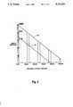
- FIG. 2is a first order graphical analysis of the relative ripple wave amplitude in the central region of a round aperture as a function of the wave propagation distance;
- FIG. 3is fragmentary plan view of a cap structure with an aperture having a polygonal transverse-sectional contour for implementing this invention
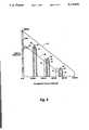
- FIG. 4provides the same graphical analysis as FIG. 3 for apertures having several different odd-sided polygonal transverse-sectional contours, including the pentagonal aperture shown in FIG. 2;
- FIG. 6is a fragmentary and diagrammatic plan view of still another apertured free ink surface level controller that is constructed in accordance with the broader aspects of this invention.
- the printer 11suitably comprises a one or two dimensional array (not shown) of droplet ejectors 12 for sequentially printing successive lines of an image on the recording medium 21 while it is being advanced (by means not shown) in a process direction, as indicated by the arrow 22.
- each of the droplet ejectors 12comprises an acoustic lens 25, which typically is an essentially diffraction-limited f/1 lens, that is formed in one face of a suitable substrate 26.
- This lens 25is acoustically coupled to the free surface 13 of the ink 14, either by the ink 14 alone (as shown) or via an intermediate single or multiple layer, liquid and/or solid acoustic coupling medium (not shown).
- the other or opposite face of the scontact with a piezoelectric transducer 27.
- the transducer 27suitably is excited by an amplitude modulated rf signal that causes it to couple an amplitude modulated, generally planar wavefront, acoustic wave into the substrate 26 for illuminating the lens 25.
- the lens 25refracts the incident radiation and bring it to focus essentially on the free ink surface 13, so the radiation pressure that is exerted against the free ink surface 13 makes brief controlled excursions to a sufficiently high pressure level for ejecting individual droplets of ink 15 therefrom under the control of amplitude modulated rf signal that is applied to the transducer 27 (not shown).
- the transducer 27is excited at an rf frequency of about 168 MHz, and the amplitude of that rf excitation is pulsed at a pulse rate of up to about 20 KHz.
- the free ink surface 13is capped by an apertured cap structure 31 which is supported (by means not shown) so that its inner face is maintained in intimate contact with the ink 14.
- the cap structure 31has a separate aperture 32 for each of the droplet ejectors 12, so the acoustic beam that is emitted by any given one of the droplet ejectors 12 comes to focus on the free ink surface 13 more or less centrally of an aperture 32 that effectively isolates that potential ejection site from the ejection sites of the other droplet ejectors 12.
- the surface ripple waveinitially is contained within the central critical region of the aperture 32.
- the ripple wavethen propagates outwardly to the aperture sidewalls, where it is reflected back toward the center of the aperture 32, so it re-enters the central region of the aperture 32 to complete a first roundtrip.
- This propagation/reflection processrepeats itself, so the level of the free ink surface 13 in the central region of the aperture 32 is periodically perturbed, with the amplitude of this oscillatory perturbation decaying at a rate, as indicated by the line 35 in FIG. 2, that is determined by the exponential attenuation that the surface wave experiences as it propagates.
- FIG. 3there is a non-retroreflective aperture configuration 42 that can be used to increase the rate at which droplets of ink 15 can be ejected by the droplet ejector 12 asynchronously.
- This particular aperturehas a pentagonal transverse-sectional configuration, but any aperture having a substantially non-retroreflective transverse-sectional configuration will significantly increase the rate at which the troublesome free ink surface level oscillations dissipate to a negligibly low level (an amplitude no greater than about ⁇ 1/2 ⁇ ).
- the surface wave induced perturbations that occur within the central region of these even-sided aperturesstill have a strong periodicity, but their amplitude dissipates to a negligibly low level significantly faster than the perturbations that occur in the central region of aperture 32 (compare the decay rates of the curves 43-46 with the decay rate 35 and the asymptote 36 from FIG. 2.
- FIG. 5provides a similar analysis, based on the same assumptions, for several odd-sided polygonal aperture configurations.
- curves 51, 52, 53, and 55represent the surface ripple wave induced perturbations that occurs within the central region of the aperture 42 if it has a triangular, pentagonal, heptagonal or nonagonal transverse-sectional configuration, respectively. These curves show that the even numbered reflections of the surface ripple wave have no effect on the free ink surface level in the central regions of these odd-sided polygonal apertures 42.
- the amplitude of the perturbation that is produced within the central region of the aperture 42 by the first reflection of the surface ripple waveis lower for a pentagonal aperture configuration than for any of the other odd-sided aperture configurations are that analyzed (compare the peak amplitude of the curve 52 with the peak amplitudes of the curves 51, 53 and 54 for the relative amplitudes of the perturbances that are caused by the first reflection of the ripple wave). This suggests that a pentagonal aperture configuration may be optimal for some applications.
- FIG. 6illustrates a somewhat more specialized embodiment of this invention, where the geometric center 51 of each of the apertures 52 is spatially displaced from the droplet ejection site 53 of the associated droplet ejector (i.e., the focal point of the droplet ejector) by a distance that is greater than the radius of the so-called critical region of the aperture 52.
- This embodimentis particularly interesting for applications in which the surface ripple wave is attenuated to a negligibly low level by the time it completes its second roundtrip because it can be implemented for those applications by means of a cap structure that has round apertures 52.
- the apertureare round, their geometric eccentricity with respect to the ejection cites 53 of the respective droplet ejectors will cause the focal point for the reflected ripples waves within any given one of the apertures 52 to alternatively shift back and forth between the ejection site 53 and a location that is symmetrically opposed (with respect to the geometric center 51 of the aperture 52) to the ejection site 53 on their even and odd numbered reflections, respectively.
- the notion of diffusively scattering the reflected ripple wavescan be extended in accordance with the broader aspects of this invention to include the more general concept of geometrically tailoring the apertures of a cap structure of the foregoing type so that a substantial portion of the ripple wave energy that is reflected by their sidewalls is directed away from the critical regions proximate the respective droplet ejection sites, at least on the first (i.e., least attenuated) reflection of the ripple waves.
- the means transverse dimensions of the apertures shown in FIGS. 3, 4 and 5are selected to be substantially greater (at least five times greater and as much as twenty or more times greater) than the diameters of the critical regions around the droplet ejection sites. While those critical regions have been assumed to be generally circular areas, it should be noted that both the shapes and the transverse dimensions of these regions are application specific parameters that should be analytically or empirically computed when implementing this invention.
- this inventionsignificantly increases the droplet ejection rates at which the acoustic ink printers that utilize apertured cap structures for free ink surface level control can be operated asynchronously. Moreover, it will be evident that this improved performance can be achieved at little, if any, additional cost.
Landscapes
- Particle Formation And Scattering Control In Inkjet Printers (AREA)
Abstract
Description
Claims (14)
Priority Applications (1)
| Application Number | Priority Date | Filing Date | Title |
|---|---|---|---|
| US07/815,002US5216451A (en) | 1992-12-27 | 1992-12-27 | Surface ripple wave diffusion in apertured free ink surface level controllers for acoustic ink printers |
Applications Claiming Priority (1)
| Application Number | Priority Date | Filing Date | Title |
|---|---|---|---|
| US07/815,002US5216451A (en) | 1992-12-27 | 1992-12-27 | Surface ripple wave diffusion in apertured free ink surface level controllers for acoustic ink printers |
Publications (1)
| Publication Number | Publication Date |
|---|---|
| US5216451Atrue US5216451A (en) | 1993-06-01 |
Family
ID=25216586
Family Applications (1)
| Application Number | Title | Priority Date | Filing Date |
|---|---|---|---|
| US07/815,002Expired - LifetimeUS5216451A (en) | 1992-12-27 | 1992-12-27 | Surface ripple wave diffusion in apertured free ink surface level controllers for acoustic ink printers |
Country Status (1)
| Country | Link |
|---|---|
| US (1) | US5216451A (en) |
Cited By (30)
| Publication number | Priority date | Publication date | Assignee | Title |
|---|---|---|---|---|
| EP0636479A3 (en)* | 1993-07-30 | 1995-06-28 | Xerox Corp | Structure of a cover for drop emitters. |
| US5565113A (en)* | 1994-05-18 | 1996-10-15 | Xerox Corporation | Lithographically defined ejection units |
| US5591490A (en)* | 1994-05-18 | 1997-01-07 | Xerox Corporation | Acoustic deposition of material layers |
| US5631678A (en)* | 1994-12-05 | 1997-05-20 | Xerox Corporation | Acoustic printheads with optical alignment |
| US5706414A (en)* | 1993-10-18 | 1998-01-06 | Hewlett-Packard Company | Dot depletion in pixel-array printing |
| US5821958A (en)* | 1995-11-13 | 1998-10-13 | Xerox Corporation | Acoustic ink printhead with variable size droplet ejection openings |
| US6045208A (en)* | 1994-07-11 | 2000-04-04 | Kabushiki Kaisha Toshiba | Ink-jet recording device having an ultrasonic generating element array |
| US6302524B1 (en) | 1998-10-13 | 2001-10-16 | Xerox Corporation | Liquid level control in an acoustic droplet emitter |
| US6309047B1 (en) | 1999-11-23 | 2001-10-30 | Xerox Corporation | Exceeding the surface settling limit in acoustic ink printing |
| US6318852B1 (en) | 1998-12-30 | 2001-11-20 | Xerox Corporation | Color gamut extension of an ink composition |
| US6328421B1 (en)* | 1995-08-22 | 2001-12-11 | Nec Corporation | Fluid drop projecting head using taper-shaped chamber for generating a converging surface wave |
| US6364454B1 (en) | 1998-09-30 | 2002-04-02 | Xerox Corporation | Acoustic ink printing method and system for improving uniformity by manipulating nonlinear characteristics in the system |
| US6416163B1 (en) | 1999-11-22 | 2002-07-09 | Xerox Corporation | Printhead array compensation device designs |
| US6450615B2 (en) | 1997-02-19 | 2002-09-17 | Nec Corporation | Ink jet printing apparatus and method using a pressure generating device to induce surface waves in an ink meniscus |
| US20030012892A1 (en)* | 2001-03-30 | 2003-01-16 | Lee David Soong-Hua | Precipitation of solid particles from droplets formed using focused acoustic energy |
| US20030052943A1 (en)* | 2000-09-25 | 2003-03-20 | Ellson Richard N. | Acoustic ejection of fluids from a plurality of reservoirs |
| US6548308B2 (en) | 2000-09-25 | 2003-04-15 | Picoliter Inc. | Focused acoustic energy method and device for generating droplets of immiscible fluids |
| US20030085952A1 (en)* | 2001-11-05 | 2003-05-08 | Williams Roger O | Apparatus and method for controlling the free surface of liquid in a well plate |
| US20030133842A1 (en)* | 2000-12-12 | 2003-07-17 | Williams Roger O. | Acoustically mediated fluid transfer methods and uses thereof |
| US20030138852A1 (en)* | 2000-09-25 | 2003-07-24 | Ellson Richard N. | High density molecular arrays on porous surfaces |
| US6612686B2 (en) | 2000-09-25 | 2003-09-02 | Picoliter Inc. | Focused acoustic energy in the preparation and screening of combinatorial libraries |
| US6642061B2 (en) | 2000-09-25 | 2003-11-04 | Picoliter Inc. | Use of immiscible fluids in droplet ejection through application of focused acoustic energy |
| US20040102742A1 (en)* | 2002-11-27 | 2004-05-27 | Tuyl Michael Van | Wave guide with isolated coupling interface |
| US20040112980A1 (en)* | 2002-12-19 | 2004-06-17 | Reichel Charles A. | Acoustically mediated liquid transfer method for generating chemical libraries |
| US6808934B2 (en) | 2000-09-25 | 2004-10-26 | Picoliter Inc. | High-throughput biomolecular crystallization and biomolecular crystal screening |
| US6925856B1 (en) | 2001-11-07 | 2005-08-09 | Edc Biosystems, Inc. | Non-contact techniques for measuring viscosity and surface tension information of a liquid |
| US7083117B2 (en) | 2001-10-29 | 2006-08-01 | Edc Biosystems, Inc. | Apparatus and method for droplet steering |
| US20090301550A1 (en)* | 2007-12-07 | 2009-12-10 | Sunprint Inc. | Focused acoustic printing of patterned photovoltaic materials |
| US20100184244A1 (en)* | 2009-01-20 | 2010-07-22 | SunPrint, Inc. | Systems and methods for depositing patterned materials for solar panel production |
| CN107696701A (en)* | 2016-08-09 | 2018-02-16 | 精工爱普生株式会社 | Tape deck |
Citations (3)
| Publication number | Priority date | Publication date | Assignee | Title |
|---|---|---|---|---|
| US4751530A (en)* | 1986-12-19 | 1988-06-14 | Xerox Corporation | Acoustic lens arrays for ink printing |
| US5028937A (en)* | 1989-05-30 | 1991-07-02 | Xerox Corporation | Perforated membranes for liquid contronlin acoustic ink printing |
| US5041849A (en)* | 1989-12-26 | 1991-08-20 | Xerox Corporation | Multi-discrete-phase Fresnel acoustic lenses and their application to acoustic ink printing |
- 1992
- 1992-12-27USUS07/815,002patent/US5216451A/ennot_activeExpired - Lifetime
Patent Citations (3)
| Publication number | Priority date | Publication date | Assignee | Title |
|---|---|---|---|---|
| US4751530A (en)* | 1986-12-19 | 1988-06-14 | Xerox Corporation | Acoustic lens arrays for ink printing |
| US5028937A (en)* | 1989-05-30 | 1991-07-02 | Xerox Corporation | Perforated membranes for liquid contronlin acoustic ink printing |
| US5041849A (en)* | 1989-12-26 | 1991-08-20 | Xerox Corporation | Multi-discrete-phase Fresnel acoustic lenses and their application to acoustic ink printing |
Cited By (52)
| Publication number | Priority date | Publication date | Assignee | Title |
|---|---|---|---|---|
| EP0636479A3 (en)* | 1993-07-30 | 1995-06-28 | Xerox Corp | Structure of a cover for drop emitters. |
| US5706414A (en)* | 1993-10-18 | 1998-01-06 | Hewlett-Packard Company | Dot depletion in pixel-array printing |
| US5565113A (en)* | 1994-05-18 | 1996-10-15 | Xerox Corporation | Lithographically defined ejection units |
| US5591490A (en)* | 1994-05-18 | 1997-01-07 | Xerox Corporation | Acoustic deposition of material layers |
| US6045208A (en)* | 1994-07-11 | 2000-04-04 | Kabushiki Kaisha Toshiba | Ink-jet recording device having an ultrasonic generating element array |
| US5631678A (en)* | 1994-12-05 | 1997-05-20 | Xerox Corporation | Acoustic printheads with optical alignment |
| US6328421B1 (en)* | 1995-08-22 | 2001-12-11 | Nec Corporation | Fluid drop projecting head using taper-shaped chamber for generating a converging surface wave |
| US5821958A (en)* | 1995-11-13 | 1998-10-13 | Xerox Corporation | Acoustic ink printhead with variable size droplet ejection openings |
| US6450615B2 (en) | 1997-02-19 | 2002-09-17 | Nec Corporation | Ink jet printing apparatus and method using a pressure generating device to induce surface waves in an ink meniscus |
| US6364454B1 (en) | 1998-09-30 | 2002-04-02 | Xerox Corporation | Acoustic ink printing method and system for improving uniformity by manipulating nonlinear characteristics in the system |
| US6302524B1 (en) | 1998-10-13 | 2001-10-16 | Xerox Corporation | Liquid level control in an acoustic droplet emitter |
| US6318852B1 (en) | 1998-12-30 | 2001-11-20 | Xerox Corporation | Color gamut extension of an ink composition |
| US6416163B1 (en) | 1999-11-22 | 2002-07-09 | Xerox Corporation | Printhead array compensation device designs |
| US6309047B1 (en) | 1999-11-23 | 2001-10-30 | Xerox Corporation | Exceeding the surface settling limit in acoustic ink printing |
| US6938987B2 (en) | 2000-09-25 | 2005-09-06 | Picoliter, Inc. | Acoustic ejection of fluids from a plurality of reservoirs |
| US20030052943A1 (en)* | 2000-09-25 | 2003-03-20 | Ellson Richard N. | Acoustic ejection of fluids from a plurality of reservoirs |
| US6548308B2 (en) | 2000-09-25 | 2003-04-15 | Picoliter Inc. | Focused acoustic energy method and device for generating droplets of immiscible fluids |
| US20040252163A1 (en)* | 2000-09-25 | 2004-12-16 | Ellson Richard N. | Acoustic ejection of fluids from a plurality of reservoirs |
| US6808934B2 (en) | 2000-09-25 | 2004-10-26 | Picoliter Inc. | High-throughput biomolecular crystallization and biomolecular crystal screening |
| US6802593B2 (en) | 2000-09-25 | 2004-10-12 | Picoliter Inc. | Acoustic ejection of fluids from a plurality of reservoirs |
| US20030138852A1 (en)* | 2000-09-25 | 2003-07-24 | Ellson Richard N. | High density molecular arrays on porous surfaces |
| US6612686B2 (en) | 2000-09-25 | 2003-09-02 | Picoliter Inc. | Focused acoustic energy in the preparation and screening of combinatorial libraries |
| US6746104B2 (en) | 2000-09-25 | 2004-06-08 | Picoliter Inc. | Method for generating molecular arrays on porous surfaces |
| US6666541B2 (en) | 2000-09-25 | 2003-12-23 | Picoliter Inc. | Acoustic ejection of fluids from a plurality of reservoirs |
| US6642061B2 (en) | 2000-09-25 | 2003-11-04 | Picoliter Inc. | Use of immiscible fluids in droplet ejection through application of focused acoustic energy |
| US20030203505A1 (en)* | 2000-12-12 | 2003-10-30 | Williams Roger O. | Acoustically mediated fluid transfer methods and uses thereof |
| US20030203386A1 (en)* | 2000-12-12 | 2003-10-30 | Williams Roger O. | Acoustically mediated fluid transfer methods and uses thereof |
| US20030211632A1 (en)* | 2000-12-12 | 2003-11-13 | Williams Roger O. | Acoustically mediated fluid transfer methods and uses thereof |
| US20030186459A1 (en)* | 2000-12-12 | 2003-10-02 | Williams Roger O. | Acoustically mediated fluid transfer methods and uses thereof |
| US20040009611A1 (en)* | 2000-12-12 | 2004-01-15 | Williams Roger O. | Acoustically mediated fluid transfer methods and uses thereof |
| US20080103054A1 (en)* | 2000-12-12 | 2008-05-01 | Williams Roger O | Acoustically mediated fluid transfer methods and uses thereof |
| US20030186460A1 (en)* | 2000-12-12 | 2003-10-02 | Williams Roger O. | Acoustically mediated fluid transfer methods and uses thereof |
| US20030133842A1 (en)* | 2000-12-12 | 2003-07-17 | Williams Roger O. | Acoustically mediated fluid transfer methods and uses thereof |
| US8137640B2 (en) | 2000-12-12 | 2012-03-20 | Williams Roger O | Acoustically mediated fluid transfer methods and uses thereof |
| US6596239B2 (en) | 2000-12-12 | 2003-07-22 | Edc Biosystems, Inc. | Acoustically mediated fluid transfer methods and uses thereof |
| US20030012892A1 (en)* | 2001-03-30 | 2003-01-16 | Lee David Soong-Hua | Precipitation of solid particles from droplets formed using focused acoustic energy |
| US6869551B2 (en) | 2001-03-30 | 2005-03-22 | Picoliter Inc. | Precipitation of solid particles from droplets formed using focused acoustic energy |
| US7083117B2 (en) | 2001-10-29 | 2006-08-01 | Edc Biosystems, Inc. | Apparatus and method for droplet steering |
| US20030085952A1 (en)* | 2001-11-05 | 2003-05-08 | Williams Roger O | Apparatus and method for controlling the free surface of liquid in a well plate |
| US6925856B1 (en) | 2001-11-07 | 2005-08-09 | Edc Biosystems, Inc. | Non-contact techniques for measuring viscosity and surface tension information of a liquid |
| US20040102742A1 (en)* | 2002-11-27 | 2004-05-27 | Tuyl Michael Van | Wave guide with isolated coupling interface |
| US7968060B2 (en) | 2002-11-27 | 2011-06-28 | Edc Biosystems, Inc. | Wave guide with isolated coupling interface |
| US20070296760A1 (en)* | 2002-11-27 | 2007-12-27 | Michael Van Tuyl | Wave guide with isolated coupling interface |
| US7275807B2 (en) | 2002-11-27 | 2007-10-02 | Edc Biosystems, Inc. | Wave guide with isolated coupling interface |
| US20040112980A1 (en)* | 2002-12-19 | 2004-06-17 | Reichel Charles A. | Acoustically mediated liquid transfer method for generating chemical libraries |
| US6863362B2 (en) | 2002-12-19 | 2005-03-08 | Edc Biosystems, Inc. | Acoustically mediated liquid transfer method for generating chemical libraries |
| US7429359B2 (en) | 2002-12-19 | 2008-09-30 | Edc Biosystems, Inc. | Source and target management system for high throughput transfer of liquids |
| US20040120855A1 (en)* | 2002-12-19 | 2004-06-24 | Edc Biosystems, Inc. | Source and target management system for high throughput transfer of liquids |
| US20040112978A1 (en)* | 2002-12-19 | 2004-06-17 | Reichel Charles A. | Apparatus for high-throughput non-contact liquid transfer and uses thereof |
| US20090301550A1 (en)* | 2007-12-07 | 2009-12-10 | Sunprint Inc. | Focused acoustic printing of patterned photovoltaic materials |
| US20100184244A1 (en)* | 2009-01-20 | 2010-07-22 | SunPrint, Inc. | Systems and methods for depositing patterned materials for solar panel production |
| CN107696701A (en)* | 2016-08-09 | 2018-02-16 | 精工爱普生株式会社 | Tape deck |
Similar Documents
| Publication | Publication Date | Title |
|---|---|---|
| US5216451A (en) | Surface ripple wave diffusion in apertured free ink surface level controllers for acoustic ink printers | |
| US5450107A (en) | Surface ripple wave suppression by anti-reflection in apertured free ink surface level controllers for acoustic ink printers | |
| EP0272899B1 (en) | Acoustic printheads | |
| CA2014660C (en) | Perforated membranes for liquid control in acoustic ink printing | |
| US4697195A (en) | Nozzleless liquid droplet ejectors | |
| EP0421718B1 (en) | Ink drop printhead | |
| EP0272154A2 (en) | Acoustic printheads | |
| JPH0635177B2 (en) | Printhead for acoustic printing | |
| US5821958A (en) | Acoustic ink printhead with variable size droplet ejection openings | |
| EP0479327A2 (en) | Ink jet recording head | |
| US7207651B2 (en) | Inkjet printing apparatus | |
| US6467877B2 (en) | Method and apparatus for high resolution acoustic ink printing | |
| EP0273664A2 (en) | Droplet ejectors | |
| EP0549243B1 (en) | Surface ripple wave diffusion by non-retroreflective aperture configurations for acoustic ink printers | |
| JPH0419026B2 (en) | ||
| US6336707B1 (en) | Recording element and recording device | |
| JP2939504B2 (en) | Ink jet recording apparatus and ink jet recording method | |
| US6302524B1 (en) | Liquid level control in an acoustic droplet emitter | |
| JPH0775890B2 (en) | Acoustic ink printer | |
| EP0216589B1 (en) | Leaky rayleigh wave nozzleless liquid droplet ejectors | |
| JPS58501276A (en) | printing device | |
| EP0739732B1 (en) | Variable focal length acoustic ink printhead | |
| JPS63166546A (en) | Dilute array for acoustic printing | |
| JP3432934B2 (en) | Ink jet recording device | |
| JP3466829B2 (en) | Ink jet recording device |
Legal Events
| Date | Code | Title | Description |
|---|---|---|---|
| AS | Assignment | Owner name:XEROX CORPORATION, A CORP. OF NY, CONNECTICUT Free format text:ASSIGNMENT OF ASSIGNORS INTEREST.;ASSIGNORS:RAWSON, ERIC G.;ELROD, SCOTT A.;HADIMIOGLU, BABUR B.;AND OTHERS;REEL/FRAME:006039/0331;SIGNING DATES FROM 19920218 TO 19920224 | |
| STCF | Information on status: patent grant | Free format text:PATENTED CASE | |
| FPAY | Fee payment | Year of fee payment:4 | |
| FPAY | Fee payment | Year of fee payment:8 | |
| AS | Assignment | Owner name:BANK ONE, NA, AS ADMINISTRATIVE AGENT, ILLINOIS Free format text:SECURITY INTEREST;ASSIGNOR:XEROX CORPORATION;REEL/FRAME:013153/0001 Effective date:20020621 | |
| AS | Assignment | Owner name:JPMORGAN CHASE BANK, AS COLLATERAL AGENT, TEXAS Free format text:SECURITY AGREEMENT;ASSIGNOR:XEROX CORPORATION;REEL/FRAME:015134/0476 Effective date:20030625 Owner name:JPMORGAN CHASE BANK, AS COLLATERAL AGENT,TEXAS Free format text:SECURITY AGREEMENT;ASSIGNOR:XEROX CORPORATION;REEL/FRAME:015134/0476 Effective date:20030625 | |
| FPAY | Fee payment | Year of fee payment:12 | |
| AS | Assignment | Owner name:XEROX CORPORATION, CONNECTICUT Free format text:RELEASE BY SECURED PARTY;ASSIGNOR:JPMORGAN CHASE BANK, N.A. AS SUCCESSOR-IN-INTEREST ADMINISTRATIVE AGENT AND COLLATERAL AGENT TO JPMORGAN CHASE BANK;REEL/FRAME:066728/0193 Effective date:20220822 |