US5216233A - Versatile RF terminal-scanner system - Google Patents
Versatile RF terminal-scanner systemDownload PDFInfo
- Publication number
- US5216233A US5216233AUS07/966,907US96690792AUS5216233AUS 5216233 AUS5216233 AUS 5216233AUS 96690792 AUS96690792 AUS 96690792AUS 5216233 AUS5216233 AUS 5216233A
- Authority
- US
- United States
- Prior art keywords
- data
- scanner
- terminal
- data capture
- handheld
- Prior art date
- Legal status (The legal status is an assumption and is not a legal conclusion. Google has not performed a legal analysis and makes no representation as to the accuracy of the status listed.)
- Expired - Lifetime
Links
Images


Classifications
- G—PHYSICS
- G06—COMPUTING OR CALCULATING; COUNTING
- G06K—GRAPHICAL DATA READING; PRESENTATION OF DATA; RECORD CARRIERS; HANDLING RECORD CARRIERS
- G06K7/00—Methods or arrangements for sensing record carriers, e.g. for reading patterns
- G06K7/10—Methods or arrangements for sensing record carriers, e.g. for reading patterns by electromagnetic radiation, e.g. optical sensing; by corpuscular radiation
- G06K7/10009—Methods or arrangements for sensing record carriers, e.g. for reading patterns by electromagnetic radiation, e.g. optical sensing; by corpuscular radiation sensing by radiation using wavelengths larger than 0.1 mm, e.g. radio-waves or microwaves
- G06K7/10316—Methods or arrangements for sensing record carriers, e.g. for reading patterns by electromagnetic radiation, e.g. optical sensing; by corpuscular radiation sensing by radiation using wavelengths larger than 0.1 mm, e.g. radio-waves or microwaves using at least one antenna particularly designed for interrogating the wireless record carriers
- G06K7/10346—Methods or arrangements for sensing record carriers, e.g. for reading patterns by electromagnetic radiation, e.g. optical sensing; by corpuscular radiation sensing by radiation using wavelengths larger than 0.1 mm, e.g. radio-waves or microwaves using at least one antenna particularly designed for interrogating the wireless record carriers the antenna being of the far field type, e.g. HF types or dipoles
- G—PHYSICS
- G06—COMPUTING OR CALCULATING; COUNTING
- G06K—GRAPHICAL DATA READING; PRESENTATION OF DATA; RECORD CARRIERS; HANDLING RECORD CARRIERS
- G06K17/00—Methods or arrangements for effecting co-operative working between equipments covered by two or more of main groups G06K1/00 - G06K15/00, e.g. automatic card files incorporating conveying and reading operations
- G06K17/0022—Methods or arrangements for effecting co-operative working between equipments covered by two or more of main groups G06K1/00 - G06K15/00, e.g. automatic card files incorporating conveying and reading operations arrangements or provisions for transferring data to distant stations, e.g. from a sensing device
- G—PHYSICS
- G06—COMPUTING OR CALCULATING; COUNTING
- G06K—GRAPHICAL DATA READING; PRESENTATION OF DATA; RECORD CARRIERS; HANDLING RECORD CARRIERS
- G06K7/00—Methods or arrangements for sensing record carriers, e.g. for reading patterns
- G06K7/10—Methods or arrangements for sensing record carriers, e.g. for reading patterns by electromagnetic radiation, e.g. optical sensing; by corpuscular radiation
- G06K7/10544—Methods or arrangements for sensing record carriers, e.g. for reading patterns by electromagnetic radiation, e.g. optical sensing; by corpuscular radiation by scanning of the records by radiation in the optical part of the electromagnetic spectrum
- G06K7/10821—Methods or arrangements for sensing record carriers, e.g. for reading patterns by electromagnetic radiation, e.g. optical sensing; by corpuscular radiation by scanning of the records by radiation in the optical part of the electromagnetic spectrum further details of bar or optical code scanning devices
- G06K7/10881—Methods or arrangements for sensing record carriers, e.g. for reading patterns by electromagnetic radiation, e.g. optical sensing; by corpuscular radiation by scanning of the records by radiation in the optical part of the electromagnetic spectrum further details of bar or optical code scanning devices constructional details of hand-held scanners
- G—PHYSICS
- G06—COMPUTING OR CALCULATING; COUNTING
- G06K—GRAPHICAL DATA READING; PRESENTATION OF DATA; RECORD CARRIERS; HANDLING RECORD CARRIERS
- G06K7/00—Methods or arrangements for sensing record carriers, e.g. for reading patterns
- G06K7/10—Methods or arrangements for sensing record carriers, e.g. for reading patterns by electromagnetic radiation, e.g. optical sensing; by corpuscular radiation
- G06K7/10544—Methods or arrangements for sensing record carriers, e.g. for reading patterns by electromagnetic radiation, e.g. optical sensing; by corpuscular radiation by scanning of the records by radiation in the optical part of the electromagnetic spectrum
- G06K7/10821—Methods or arrangements for sensing record carriers, e.g. for reading patterns by electromagnetic radiation, e.g. optical sensing; by corpuscular radiation by scanning of the records by radiation in the optical part of the electromagnetic spectrum further details of bar or optical code scanning devices
- G06K7/1098—Methods or arrangements for sensing record carriers, e.g. for reading patterns by electromagnetic radiation, e.g. optical sensing; by corpuscular radiation by scanning of the records by radiation in the optical part of the electromagnetic spectrum further details of bar or optical code scanning devices the scanning arrangement having a modular construction
- G—PHYSICS
- G06—COMPUTING OR CALCULATING; COUNTING
- G06K—GRAPHICAL DATA READING; PRESENTATION OF DATA; RECORD CARRIERS; HANDLING RECORD CARRIERS
- G06K2207/00—Other aspects
- G06K2207/1011—Aiming
Definitions
- This inventionrelates to the field of automatic data capture, and particularly to data capture systems for reading data such as bar code symbols on containers, and the like, and for transmitting the scanned data via a radiant energy link to a receiving station, e.g. associated with a host computer.
- an existing or standard RF terminal configurationcan be selectively adapted to diverse types of scanning technologies by means of respective scanner modules.
- a commercially available radio data terminalmay presently have an external connector fitting for transmitting operating power to bar code readers of diverse types such as CCD, various light pens and five-volt laser scanners, and for transmitting scanner data on-line to a host processor.
- a given RF data terminalmay be equipped with a scanner module such as to enable scanning of an entire bar code symbol or other data source line while the terminal-scanner module system is briefly held by one hand in scanning relationship thereto. Further respective types of noncontact scanner modules which are optimum for various applications may be selectively applied to a common RF terminal configuration.
- the handheld data capture systemmay be held in scanning position in either hand, with a frontal operating face of the data terminal facing the user, such orientation facilitating observation of a user interface means on the frontal operating face (such as a data display or the like) during scanning operation.
- a vertical median plane of the scan energy pathpreferably essentially bisects the data terminal frontal operating face along its longitudinal axis.
- the terminal frontal operating panelis held with the user's palm generally horizontal and the operating panel facing the user for optimum viewing.
- the terminalmay be grasped by the user at the end adjacent such a scanner module, and the scanner module may have a central trigger button which is readily actuated by the thumb of the hand holding the terminal.
- the plane of a sheet like scanner fieldmay preferably be inclined downwardly so as to directed toward bar codes supported at the height of a store counter top or the like.
- the scanner modulemay be shaped in general conformity to the scanner field to facilitate aiming.
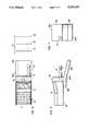
- FIG. 1is a partial somewhat diagrammatic side elevational view of a handheld data capture system in accordance with the present invention.
- FIG. 2is a partial top plan view of the data capture system of FIG. 1.
- FIG. 3is an end elevational view of the data capture system of the FIGS. 1 and 2.
- FIG. 4is a somewhat diagrammatic longitudinal sectional view showing a scanner module construction wherein different focal distances can be selected to provide different types of modules with respective different operative scanning distances but all utilizing a common scanner technology, e.g. CCD scanner technology.
- a common scanner technologye.g. CCD scanner technology.
- FIG. 5is a partial diagrammatic side elevational view showing an RF/ID scanner module applied to the standard data terminal of FIGS. 1-3.
- FIG. 6is a diagrammatic partial top plan view of the embodiment of FIG. 5.
- FIG. 7is a diagrammatic end elevational view of the embodiment of FIGS. 5 and 6.
- FIG. 8is a diagrammatic partial side elevational view showing an area image data reader module applied to the standard data terminal of FIGS. 1-3 and 5-7.
- FIG. 9is a diagrammatic partial top plan view of the embodiment of FIG. 8.
- FIG. 10is a diagrammatic end elevational view of the embodiment of FIGS. 8 and 9.
- FIGS. 1 and 2show a commercially available handheld radio data terminal 10 known as the RT2210 terminal of Norand Corporation, Cedar Rapids, Iowa.
- the RT2210 terminalis of generally rectilinear configuration with a length of 9.4 inches, a width of 3.4 inches and a height of 1.8 inches (23.9 cm ⁇ 8.6 cm ⁇ 4.6 cm) and a weight of 2.0 pounds (0.9 kg).
- a frontal operating face 11 of the terminalhas user interface means such as a keyboard with keys such as 12 and a display 14. With the terminal in an upright orientation, an antenna 15 would extend vertically from an upper end 16.
- the end wall 16 of the RT2210 terminalis provided with an externally accessible 15-position D type connector which in normal use receives a cooperating D connector with fifteen pins.
- various types of scannersare coupled to the connector 17 via cable, for example light pens, CCD bar code readers and five volt laser/laser-diode scanners, without requirement for external communication interfaces or power supplies.
- the RT2210is designed for two-way on line communication with a host computer so that accuracy of scanner data from the various scanners can be immediately verified by the host computer, and any errors can be eliminated at the transaction level. An audio annunciator in the terminal will signal whether a scanned bar code has been properly or improperly decoded.
- a scanner module 20is shown with securing means 21, 22 forming a socket for receiving the end 16 of the terminal 10.
- the scanner module 20carries an external data coupler means 24 which is arranged to mate with the terminal external data coupler means 17 as the scanner module is affixed to end 16 of the terminal.
- the securing means 22forms a flexible latch which snaps into engagement with a marginal rim 23 extending about the perimeter of the operating face 11 of the terminal.
- the module 20is constructed so that with the top edge 21A resting against the bottom 24 of the terminal, and with parts 10 and 20 axially aligned, the coupler means 17, 24, e.g.
- the latch finger 22is initially deflected upwardly by a somewhat rounded forward edge 25 of the housing, after which the finger 22 snaps downwardly to interlock its latch portion 22a behind the marginal rim 23 to securely hold parts 10 and 20 together to form a unitary data capture assembly.
- the scanner modulemay have a housing 30 with a lower shaped section 30A which may contain the scanner components and an upper section 30B which may contain the processing electronics.
- the scannermay direct scan energy along a path such as indicated at 31, FIG. 1, with lateral margins as at 31A, 31B, FIG. 2.
- a data source line (or lines)such as indicated at 33 may comprise a complete bar code symbol or other complete line of information which is to be automatically read by the scanner module.
- a complete image of the data source line or linesmay enter the scanner module at a scanner window 35 via a data source image path 36 and be converted by the scanner module to data for transmission to a host processor or the like.
- scanner modulessuch as 20 may each be applied to the terminal 10 as shown, but may be configured to accommodate scanners with diverse scanner technologies such as the scanner technologies shown in the following pending patent applications:
- scanner components of the fourth figureessentially fit within the scanner housing section 30A and emit a sheet like illumination beam along the scan energy path 31.
- the light energymay occupy a spectrum from 400 nanometers to 1,050 nanometers if a xenon flash tube source (60) is used in such fourth figure.
- a complete image of the data source line 33e.g. a bar code symbol (11) as shown on a product container (12) in the first figure of U.S. Pat. No. 4,766,300, is transmitted along a data source image path 36 which may extend along an optical axis (64) as indicated in the fourth figure of U.S. Pat.
- a scanner such as shown in U.S. Pat. No. 4,766,300is a noncontact scanner since it is capable of reading data at a substantial distance in front of its housing end face corresponding to end face 37, FIGS. 1 and 3, (e.g. ten millimeters).
- the scanner of U.S. Pat. No. 4,766,300has a substantial depth of field, e.g. ten millimeters, so as to be capable of reading a curved bar code label 1.8 inches long, having a radius of curvature greater than 1.25 inches, where the bar code has a minimum bar/space width of 7.5 mils (0.0075 inch), a contrast ratio of 50% or greater, and bars and spaces within ten percent of their nominal size, as described at col. 16 of U.S. Pat. No. 4,766,300.
- lateral margin lines 31A, 31Brepresent the lateral margins of a scan energy path and the resultant lateral margins of a source data image path e.g. for a source data image entering window 35
- a path median planeis indicated at 40 which is perpendicular to the plane of frontal side 11 of the terminal and which substantially bisects the frontal side 11 as well as bisecting scan window 35.
- the actuating button (18) of the first figure of U.S. Pat. No. 4,766,300may be located centrally of upper housing 30B, as indicated at 42 in FIG. 2, so as to be actuated with the thumb (indicated at 43, FIG. 1) of either hand.
- the usermay support the complete assembly in either hand, with the palm supporting underside 24 of terminal 10, e.g. adjacent module part 21 (as indicated at 44 in FIG. 1).
- a data source line or lines at 33is readily visible to the user also, so that the scanner module may be conveniently aimed and triggered at 42, to effect a reading.
- the keys such as 12are readily actuated by the free hand of the user, e.g. to enter quantity information or to manually enter data which proves not to be automatically readable.
- the housing part 30Bmay be equipped to decode bar code readings, so that decoded bar code information, verified as accurate, is sent via the mating coupling means 24, 17 to the terminal 10, for on-line transmission to a host processor, e.g. via antenna 15.
- housing 30to contain the scanners of each of the incorporated applications will be apparent to those skilled in the art from the foregoing description in relation to U.S. Pat. No. 4,766,300.
- a family of scanner modules selectively attachable to a given data terminalmay comprise either a set of scanners utilizing respective different scanner technologies (such as CCD, laser beam scan, and RF/ID), or a set of scanners of the same basic technology but of different characteristics, or a combination of scanner modules of different characteristics and scanner modules using different technologies as well.
- a familymay include laser tube and laser diode cyclically deflected beam scanners with different spectral characteristics optimum for different types of bar codes and reading distances, and may also include CCD scanners having their optics adjusted to provide different reading distances in front of the module.
- an extendermay extend from end face 16 for a distance equal to module thickness at section 30B.
- the moduleseach may have an opening such as indicated at 50 conforming with the diameter of the base part 51 of the antenna 15 so that correct alignment of connectors 17 and 24 is assured as the surface 21A slides along the housing undersurface 24 during assembly of the respective modules such as 20 with the housing 10.
- FIG. 4shows elements corresponding to those of the third figure of the incorporated patent application (A) referred to hereinabove. Reference numerals from application (A) have been indicated in FIG. 4, but with the prefix "4-" to distinguish them from other reference numerals herein. Instead of the adjustment means (102, 103, 105, 111) of the incorporated application (A) FIG. 4 shows one of series of modules 400 having respective different fixed focal lengths together covering the range of adjustment provided by the adjustment means of the incorporate application (A).
- Reference numeral 401indicates diagrammatically that lens barrel 4-90 is to be fixed in a respective selected position for each respective different module, rather than having the lens barrel 4-90 motor driven to different positions.
- Different moduleswill have lug 402 of the lens barrel locked in respective different positions to cover a range of scan distances, such as contemplated in the incorporated application. Then by selecting modules such as 400 with appropriate fixed focal distances, a data terminal such as 10 may be adjusted to respective desired scanning distances appropriate to different fields of use.
- an antenna extender 405corresponds with base section 51 in serving to accurately guide the various modules so as to insure proper mating of the connectors.
- an active antenna part 415is pivotal at 416 on the extender 405 so that it may be swung from a longitudinal or generally horizontal position as indicated by dash lines at 415A, to a generally upright position (with frontal panel 11 horizontal) as shown in solid lines.
- the antenna 415does not obstruct removal of the scanner modules since it will swing to the longitudinal position 415A as the module is unsnapped from the terminal and removed.
- FIGS. 5, 6 and 7show the RF data terminal 10 with a RF/ID module 420 having a suitable electromagnetic field permeable housing 421 which contains the RF/ID antenna 422, and other suitable components.
- the angle of housing part 421Amay be such that with the antenna 422 horizontal, the terminal 10 will be at an angle to a horizontal plane providing for convenient viewing of the terminal display 14 by the user holding the assembled device in either hand.
- Different modulesmay provide different operating frequencies and RF/ID antennas so as to be adapted to respective different scanning distances such as represented at S1, S2, S3 covering a desired scanning range R.
- FIGS. 8, 9 and 10show an area type image reader module 440 applied to the terminal 10.
- Such modulesmay conform with incorporated application (C) referred to hereinabove.
- FIG. 10shows a generally circular window 441, accommodating a circular xenon light source 442 such as shown (at 11) in the second figure of the incorporated application.
- Different modulessuch as 440 may have lens systems with different focal distances so as to accommodate reading over a range of scanning distances (such as indicted diagrammatically at S11, S12, S13 in FIG. 9, and covering a range R1).
- Modules for the terminal 10may utilize other scanner technologies. For example, instead of rotating mirror scanning of a laser beam, a similar rotating mirror scanning may be used with a light emitting diode beam source. Instead of one or two photodetectors, photosensor (e.g. CCD) line or area arrays may be used with cyclical laser beam scanning or cyclical LED scanning. For area arrays, an elongated beam cross section may be used and/or area raster type deflection of the beam (e.g. with respect to orthogonal x and y axes). Such technologies would be housed in module 20 of FIGS. 1, 2 and 3, for example, or module 440, FIGS.
- area arraysan elongated beam cross section may be used and/or area raster type deflection of the beam (e.g. with respect to orthogonal x and y axes).
- Such technologieswould be housed
- Incorporated application (B)shows a scanning beam arrangement in the fourth figure which is adaptable to the module configuration of FIGS. 8, 9 and 10, for example.
- the antenna parts external to wall 16may be part of the scanner module and removable therewith. Also any of the antenna parts external to the module may be deflectable in any suitable direction, e.g. so as to be generally upright during scanning as described for antenna part 415, FIG. 4.
Landscapes
- Engineering & Computer Science (AREA)
- Physics & Mathematics (AREA)
- Electromagnetism (AREA)
- Health & Medical Sciences (AREA)
- Theoretical Computer Science (AREA)
- General Physics & Mathematics (AREA)
- Toxicology (AREA)
- General Health & Medical Sciences (AREA)
- Artificial Intelligence (AREA)
- Computer Vision & Pattern Recognition (AREA)
- General Engineering & Computer Science (AREA)
- Computer Networks & Wireless Communication (AREA)
- Image Input (AREA)
- Facsimile Scanning Arrangements (AREA)
Abstract
Description
Claims (36)
Priority Applications (3)
| Application Number | Priority Date | Filing Date | Title |
|---|---|---|---|
| US07/966,907US5216233A (en) | 1989-03-09 | 1992-10-26 | Versatile RF terminal-scanner system |
| US08/851,338US5763867A (en) | 1989-03-09 | 1997-05-05 | Versatile terminal for use in a radio frequency identification system |
| US09/094,091US5962837A (en) | 1989-03-09 | 1998-06-09 | Versatile RF terminal scanner system |
Applications Claiming Priority (2)
| Application Number | Priority Date | Filing Date | Title |
|---|---|---|---|
| US32193289A | 1989-03-09 | 1989-03-09 | |
| US07/966,907US5216233A (en) | 1989-03-09 | 1992-10-26 | Versatile RF terminal-scanner system |
Related Parent Applications (1)
| Application Number | Title | Priority Date | Filing Date |
|---|---|---|---|
| US32193289AContinuation | 1989-03-09 | 1989-03-09 |
Related Child Applications (1)
| Application Number | Title | Priority Date | Filing Date |
|---|---|---|---|
| US7059693AContinuation | 1989-03-09 | 1993-05-28 |
Publications (1)
| Publication Number | Publication Date |
|---|---|
| US5216233Atrue US5216233A (en) | 1993-06-01 |
Family
ID=26983187
Family Applications (3)
| Application Number | Title | Priority Date | Filing Date |
|---|---|---|---|
| US07/966,907Expired - LifetimeUS5216233A (en) | 1989-03-09 | 1992-10-26 | Versatile RF terminal-scanner system |
| US08/851,338Expired - Fee RelatedUS5763867A (en) | 1989-03-09 | 1997-05-05 | Versatile terminal for use in a radio frequency identification system |
| US09/094,091Expired - Fee RelatedUS5962837A (en) | 1989-03-09 | 1998-06-09 | Versatile RF terminal scanner system |
Family Applications After (2)
| Application Number | Title | Priority Date | Filing Date |
|---|---|---|---|
| US08/851,338Expired - Fee RelatedUS5763867A (en) | 1989-03-09 | 1997-05-05 | Versatile terminal for use in a radio frequency identification system |
| US09/094,091Expired - Fee RelatedUS5962837A (en) | 1989-03-09 | 1998-06-09 | Versatile RF terminal scanner system |
Country Status (1)
| Country | Link |
|---|---|
| US (3) | US5216233A (en) |
Cited By (70)
| Publication number | Priority date | Publication date | Assignee | Title |
|---|---|---|---|---|
| WO1994014136A1 (en)* | 1992-12-04 | 1994-06-23 | Psc, Inc. | Optical symbol (bar code) reading systems and devices |
| WO1994018642A1 (en)* | 1993-02-08 | 1994-08-18 | Indala Corporation | Hand-held dual technology identification tag reading head |
| US5410141A (en)* | 1989-06-07 | 1995-04-25 | Norand | Hand-held data capture system with interchangable modules |
| WO1995013577A1 (en)* | 1993-11-03 | 1995-05-18 | Computec Oy | Computer for a vehicle |
| US5750975A (en)* | 1995-08-25 | 1998-05-12 | Teletransactions, Inc. | Hand held bar code dataform reader having a rotatable reading assembly |
| US5756981A (en)* | 1992-02-27 | 1998-05-26 | Symbol Technologies, Inc. | Optical scanner for reading and decoding one- and-two-dimensional symbologies at variable depths of field including memory efficient high speed image processing means and high accuracy image analysis means |
| US5796088A (en)* | 1995-08-15 | 1998-08-18 | Teletransactions, Inc. | Hand held portable bar code dataform reader having a rotatable reader module portion |
| US5825617A (en)* | 1992-10-02 | 1998-10-20 | Teletransactions, Inc. | Workslate computer having modular device docking stations on horizontal and vertical side portions |
| US5834753A (en)* | 1986-08-08 | 1998-11-10 | Norand Corporation | Laser scanner module having integral interface with hand-held data capture terminal proximity and label sensing, and enhanced sensitivity and power efficiency |
| US5850187A (en)* | 1996-03-27 | 1998-12-15 | Amtech Corporation | Integrated electronic tag reader and wireless communication link |
| US5854737A (en)* | 1993-11-09 | 1998-12-29 | Fujitsu Limited | Information processing system using portable terminal unit and data communication adapter having biased connector |
| US5898162A (en)* | 1989-06-07 | 1999-04-27 | Norand Corporation | Hand-held data capture system with interchangeable modules |
| US5909209A (en)* | 1995-12-27 | 1999-06-01 | Lucent Technologies, Inc. | Combination mouse and area imager |
| US6000619A (en)* | 1992-02-21 | 1999-12-14 | Spectra-Physics Scanning Systems, Inc. | Scanner assembly |
| US6078251A (en)* | 1996-03-27 | 2000-06-20 | Intermec Ip Corporation | Integrated multi-meter and wireless communication link |
| US6076731A (en)* | 1997-04-10 | 2000-06-20 | Intermec Ip Corp. | Magnetic stripe reader with signature scanner |
| US6105004A (en)* | 1996-04-18 | 2000-08-15 | Eldat Communication, Ltd. | Product monitoring system particularly useful in merchandising and inventory control |
| US6105871A (en)* | 1992-07-16 | 2000-08-22 | Telxon Corporation | Portable bar code scanner apparatus |
| US6149062A (en)* | 1988-01-14 | 2000-11-21 | Intermec Ip Corp. | Interface with hand-held data capture terminal, proximity and label sensing, and enhanced sensitivity and power efficiency |
| US6189788B1 (en)* | 1990-12-26 | 2001-02-20 | Intermec Ip Corp. | Portable modular work station including printer and portable data collection terminal |
| US6193159B1 (en)* | 1995-01-11 | 2001-02-27 | Fujitsu Limited | Portable optical reading apparatus having a trigger key for starting reading operation thereof |
| US6193161B1 (en)* | 1998-10-23 | 2001-02-27 | Telxon Corporation | Bar code reader having independent bar code read activation data capabilities |
| US6215475B1 (en) | 1992-10-02 | 2001-04-10 | Telxon Corporation | Highly integrated portable electronic work slate unit |
| US6246995B1 (en) | 1998-05-29 | 2001-06-12 | Ncr Corporation | Product activity data collection system |
| US6253190B1 (en)* | 1995-04-28 | 2001-06-26 | Telxon Corporation | Programmable shelf tag and method for changing and updating shelf tag information |
| US6266045B1 (en) | 1994-06-30 | 2001-07-24 | Telxon Corporation | Interactive display user interface computer and method |
| US6269342B1 (en)* | 1995-04-28 | 2001-07-31 | Telxon Corporation | Programmable shelf tag system |
| US6285916B1 (en) | 1994-10-14 | 2001-09-04 | United Parcel Serivce Of America, Inc. | Multi-stage parcel tracking system |
| US6321986B1 (en)* | 1993-11-05 | 2001-11-27 | Intermec Ip Corporation | Robust machine-readable symbology and method and apparatus for printing and reading same |
| US6371375B1 (en) | 1995-09-25 | 2002-04-16 | Intermec Ip Corp. | Method and apparatus for associating data with a wireless memory device |
| US6415978B1 (en)* | 1999-05-03 | 2002-07-09 | Psc Scanning, Inc. | Multiple technology data reader for bar code labels and RFID tags |
| US6422476B1 (en) | 1993-11-05 | 2002-07-23 | Intermec Ip Corp. | Method, apparatus and character set for encoding and decoding data characters in data carriers, such as RFID tags |
| US20020162892A1 (en)* | 1990-06-07 | 2002-11-07 | Koenck Steven E. | Data processing and communications device with interchangeable modules |
| US6486769B1 (en) | 1999-12-22 | 2002-11-26 | Intermec Ip Corp. | Method and system for automatic adjustment and diagnosis of radio frequency identification systems using programmable checktags |
| US6497368B1 (en) | 1998-01-22 | 2002-12-24 | Intermec Ip Corp. | Portable data collection |
| US6634556B2 (en)* | 1988-09-19 | 2003-10-21 | Symbol Technologies, Inc. | Scan pattern generator convertible between multiple and single line patterns |
| US6665536B1 (en) | 1993-12-20 | 2003-12-16 | Broadcom Corporation | Local area network having multiple channel wireless access |
| US20030234775A1 (en)* | 2002-06-25 | 2003-12-25 | Eastman Kodak Company | Hand-held programmer for programmable liquid crystal display |
| US6697415B1 (en) | 1996-06-03 | 2004-02-24 | Broadcom Corporation | Spread spectrum transceiver module utilizing multiple mode transmission |
| US6714983B1 (en) | 1989-04-14 | 2004-03-30 | Broadcom Corporation | Modular, portable data processing terminal for use in a communication network |
| US20040134989A1 (en)* | 2003-01-09 | 2004-07-15 | Hand Held Products, Inc. | Decoder board for an optical reader utilizing a plurality of imaging formats |
| US6830181B1 (en)* | 1998-02-09 | 2004-12-14 | Intermec Ip Corp. | Combined optical and radio frequency tag reader |
| US20050150959A1 (en)* | 2004-01-09 | 2005-07-14 | John Izzo | Optical reader |
| US20060200271A1 (en)* | 2005-02-22 | 2006-09-07 | Elliott Porco | Information management system |
| US7120319B2 (en) | 1986-08-15 | 2006-10-10 | Broadcom Corporation | Data capture apparatus with handwritten data receiving component |
| US7121468B2 (en) | 1998-12-03 | 2006-10-17 | Metrologic Instruments, Inc. | Method of developing an application program for running on a wireless portable data terminal (PDT) |
| US20070016460A1 (en)* | 2005-07-14 | 2007-01-18 | Vocollect, Inc. | Task management system having selectively variable check data |
| US20070229261A1 (en)* | 2006-04-03 | 2007-10-04 | Intermec Ip Corp. | Automatic data collection device, method and article |
| US20070284441A1 (en)* | 2006-06-13 | 2007-12-13 | Joseph Walczyk | Method and apparatus for uniquely associating a bar code reading terminal to a cash register in a retail store network |
| US20080011822A1 (en)* | 2006-07-11 | 2008-01-17 | Intermec Ip Corp. | Automatic data collection device, method and article |
| US7387253B1 (en)* | 1996-09-03 | 2008-06-17 | Hand Held Products, Inc. | Optical reader system comprising local host processor and optical reader |
| US20080223935A1 (en)* | 2007-03-16 | 2008-09-18 | Intermec Ip Corp. | Systems, devices, and methods for reading machine-readable characters and human-readable characters |
| US20080252424A1 (en)* | 2005-09-21 | 2008-10-16 | Intermec Ip Corp. | Stochastic Communication Protocol Method and System For Radio Frequency Identification (Rfid) Tags Based on Coalition Formation, Such as For Tag-To-Tag Communication |
| US7446753B2 (en) | 2004-09-10 | 2008-11-04 | Hand Held Products, Inc. | Hand held computer device |
| US20090015194A1 (en)* | 1989-04-14 | 2009-01-15 | Broadcom Corporation | Portable computerized data communication device |
| US7483417B2 (en) | 1996-04-18 | 2009-01-27 | Verizon Services Corp. | Telephony communication via varied redundant networks |
| US7505785B2 (en) | 1993-10-13 | 2009-03-17 | Dataquill Limited | Data entry systems |
| WO2004049897A3 (en)* | 2002-12-03 | 2009-06-18 | Tecnomotor Eletronica Brasil | Portable body for diagnostic equipment |
| US7556203B2 (en) | 2005-06-27 | 2009-07-07 | Hand Held Products, Inc. | Method and system for linking a wireless hand held optical reader with a base unit or other wireless device |
| USD599798S1 (en) | 2004-09-10 | 2009-09-08 | Hand Held Products, Inc. | Hand held computer device |
| US20090322277A1 (en)* | 1992-11-30 | 2009-12-31 | Broadcom Corporation | Portable computerized data communication device |
| US7664097B2 (en) | 1996-04-18 | 2010-02-16 | Verizon Services Corp. | Telephone service via networking |
| US7813332B1 (en) | 1997-03-19 | 2010-10-12 | Verizon Services Corp. | Voice call alternative routing through PSTN and internet networks |
| US7817619B1 (en) | 1996-12-18 | 2010-10-19 | Verizon Services Corp. | Internet long distance telephone service |
| US7830860B2 (en) | 1997-03-11 | 2010-11-09 | Verizon Services Corp. | Packet data network voice call quality monitoring |
| US7835344B1 (en) | 1997-03-19 | 2010-11-16 | Verizon Services Corp. | Transport of caller identification information through diverse communication networks |
| US7948968B2 (en) | 1997-09-16 | 2011-05-24 | Verizon Communications Inc. | Network session management |
| US8938062B2 (en) | 1995-12-11 | 2015-01-20 | Comcast Ip Holdings I, Llc | Method for accessing service resource items that are for use in a telecommunications system |
| US20150081163A1 (en)* | 2013-09-13 | 2015-03-19 | Service Solutions U.S. Llc | Obd illuminator cable apparatus and method |
| US9191505B2 (en) | 2009-05-28 | 2015-11-17 | Comcast Cable Communications, Llc | Stateful home phone service |
Families Citing this family (32)
| Publication number | Priority date | Publication date | Assignee | Title |
|---|---|---|---|---|
| US5216233A (en)* | 1989-03-09 | 1993-06-01 | Norand Corporation | Versatile RF terminal-scanner system |
| US7077327B1 (en)* | 1990-09-17 | 2006-07-18 | Metrologic Instruments, Inc. | System for reading bar code symbols using bar code readers having RF signal transmission links with base stations |
| JPH0944621A (en)* | 1995-07-25 | 1997-02-14 | Yokohama Rubber Co Ltd:The | Information memory cell, scanner and information storage and reproducing device |
| US6543695B1 (en)* | 1996-08-02 | 2003-04-08 | Symbol Technologies, Inc. | Housing for hand held scanner |
| US6176422B1 (en) | 1996-12-16 | 2001-01-23 | The Yokohama Rubber Co., Ltd. | Information storage device, scanner and information storage and reproducing apparatus |
| US6264106B1 (en)* | 1999-12-27 | 2001-07-24 | Symbol Technologies, Inc. | Combination bar code scanner/RFID circuit |
| WO2002011019A1 (en) | 2000-08-01 | 2002-02-07 | First Usa Bank, N.A. | System and method for transponder-enabled account transactions |
| US7675503B2 (en)* | 2000-11-29 | 2010-03-09 | Ncr Corporation | Method of displaying information by a network kiosk |
| US6779246B2 (en) | 2001-04-23 | 2004-08-24 | Appleton Papers Inc. | Method and system for forming RF reflective pathways |
| US6892441B2 (en) | 2001-04-23 | 2005-05-17 | Appleton Papers Inc. | Method for forming electrically conductive pathways |
| US6910911B2 (en)* | 2002-06-27 | 2005-06-28 | Vocollect, Inc. | Break-away electrical connector |
| US7121467B2 (en)* | 2004-05-21 | 2006-10-17 | Intermec Ip Corp. | Indicators of optimum positioning of a data collection device for reading data carriers, such as RFID tags and machine-readable symbols |
| US6968994B1 (en)* | 2004-07-06 | 2005-11-29 | Nortel Networks Ltd | RF-ID for cable management and port identification |
| EP1807787A4 (en)* | 2004-11-04 | 2008-05-21 | Prec Dynamics Corp | Combined barcode scanner and radio frequency identification reader with field interpretation array |
| US20060214284A1 (en)* | 2005-03-24 | 2006-09-28 | Stuart Haden | Apparatus and method for data capture |
| US9272805B2 (en) | 2005-08-19 | 2016-03-01 | Adasa Inc. | Systems, methods, and devices for commissioning wireless sensors |
| US20090314829A1 (en)* | 2007-05-22 | 2009-12-24 | Mcallistor Clarke | Systems, Methods, and Devices for Replication of Data onto Wireless Sensors |
| US8228198B2 (en)* | 2005-08-19 | 2012-07-24 | Adasa Inc. | Systems, methods, and devices for commissioning wireless sensors |
| US7679510B2 (en) | 2006-02-06 | 2010-03-16 | Hershey Chocolate And Confectionary Corporation | RFID product identification and tracking system |
| USD626949S1 (en) | 2008-02-20 | 2010-11-09 | Vocollect Healthcare Systems, Inc. | Body-worn mobile device |
| CA2638361A1 (en)* | 2008-07-29 | 2010-01-29 | Psion Teklogix Inc. | Portable terminal and pistol grip sled with optimized scan angle |
| US8386261B2 (en) | 2008-11-14 | 2013-02-26 | Vocollect Healthcare Systems, Inc. | Training/coaching system for a voice-enabled work environment |
| US8659397B2 (en) | 2010-07-22 | 2014-02-25 | Vocollect, Inc. | Method and system for correctly identifying specific RFID tags |
| USD643400S1 (en) | 2010-08-19 | 2011-08-16 | Vocollect Healthcare Systems, Inc. | Body-worn mobile device |
| USD643013S1 (en) | 2010-08-20 | 2011-08-09 | Vocollect Healthcare Systems, Inc. | Body-worn mobile device |
| US11093722B2 (en) | 2011-12-05 | 2021-08-17 | Adasa Inc. | Holonomic RFID reader |
| US10846497B2 (en) | 2011-12-05 | 2020-11-24 | Adasa Inc. | Holonomic RFID reader |
| US10476130B2 (en) | 2011-12-05 | 2019-11-12 | Adasa Inc. | Aerial inventory antenna |
| US9780435B2 (en) | 2011-12-05 | 2017-10-03 | Adasa Inc. | Aerial inventory antenna |
| US10050330B2 (en) | 2011-12-05 | 2018-08-14 | Adasa Inc. | Aerial inventory antenna |
| US9747480B2 (en) | 2011-12-05 | 2017-08-29 | Adasa Inc. | RFID and robots for multichannel shopping |
| US10628723B2 (en) | 2018-07-10 | 2020-04-21 | Datamax-O'neil Corporation | Methods, systems, and apparatuses for encoding a radio frequency identification (RFID) inlay |
Citations (6)
| Publication number | Priority date | Publication date | Assignee | Title |
|---|---|---|---|---|
| US3826900A (en)* | 1972-10-13 | 1974-07-30 | Ncr | Cordless scanning probe |
| US4415065A (en)* | 1980-11-17 | 1983-11-15 | Sandstedt Gary O | Restaurant or retail vending facility |
| US4621189A (en)* | 1985-10-08 | 1986-11-04 | Telxon Corporation | Hand held data entry apparatus |
| US4766300A (en)* | 1984-08-06 | 1988-08-23 | Norand Corporation | Instant portable bar code reader |
| US4845350A (en)* | 1982-01-25 | 1989-07-04 | Symbol Technologies, Inc. | Narrow-bodied, single-and twin-windowed portable laser scanning head for reading bar code symbols |
| US4916441A (en)* | 1988-09-19 | 1990-04-10 | Clinicom Incorporated | Portable handheld terminal |
Family Cites Families (8)
| Publication number | Priority date | Publication date | Assignee | Title |
|---|---|---|---|---|
| US4835372A (en)* | 1985-07-19 | 1989-05-30 | Clincom Incorporated | Patient care system |
| US5059778A (en)* | 1986-09-29 | 1991-10-22 | Mars Incorporated | Portable data scanner apparatus |
| US4970379A (en)* | 1987-04-30 | 1990-11-13 | Norand Corporation | Bar code scanner system and scanner circuitry therefor |
| GB2206432B (en)* | 1987-05-20 | 1991-07-24 | Furuno Electric Co | Bar code printing and/or reading apparatus |
| US4906843A (en)* | 1987-12-31 | 1990-03-06 | Marq Technolgies | Combination mouse, optical scanner and digitizer puck |
| US5055660A (en)* | 1988-06-16 | 1991-10-08 | Avicom International, Inc. | Portable transaction monitoring unit for transaction monitoring and security control systems |
| US5107100A (en)* | 1988-11-17 | 1992-04-21 | Symbol Technologies, Inc. | Portable scanner with on-board keyboard, display, transceiver and printer |
| US5216233A (en)* | 1989-03-09 | 1993-06-01 | Norand Corporation | Versatile RF terminal-scanner system |
- 1992
- 1992-10-26USUS07/966,907patent/US5216233A/ennot_activeExpired - Lifetime
- 1997
- 1997-05-05USUS08/851,338patent/US5763867A/ennot_activeExpired - Fee Related
- 1998
- 1998-06-09USUS09/094,091patent/US5962837A/ennot_activeExpired - Fee Related
Patent Citations (7)
| Publication number | Priority date | Publication date | Assignee | Title |
|---|---|---|---|---|
| US3826900A (en)* | 1972-10-13 | 1974-07-30 | Ncr | Cordless scanning probe |
| US4415065A (en)* | 1980-11-17 | 1983-11-15 | Sandstedt Gary O | Restaurant or retail vending facility |
| US4845350A (en)* | 1982-01-25 | 1989-07-04 | Symbol Technologies, Inc. | Narrow-bodied, single-and twin-windowed portable laser scanning head for reading bar code symbols |
| US4845350B1 (en)* | 1982-01-25 | 1991-04-30 | Narrow-bodied,single-and twin-windowed portable laser scanning head for reading bar code symbols | |
| US4766300A (en)* | 1984-08-06 | 1988-08-23 | Norand Corporation | Instant portable bar code reader |
| US4621189A (en)* | 1985-10-08 | 1986-11-04 | Telxon Corporation | Hand held data entry apparatus |
| US4916441A (en)* | 1988-09-19 | 1990-04-10 | Clinicom Incorporated | Portable handheld terminal |
Cited By (113)
| Publication number | Priority date | Publication date | Assignee | Title |
|---|---|---|---|---|
| US5834753A (en)* | 1986-08-08 | 1998-11-10 | Norand Corporation | Laser scanner module having integral interface with hand-held data capture terminal proximity and label sensing, and enhanced sensitivity and power efficiency |
| US7120319B2 (en) | 1986-08-15 | 2006-10-10 | Broadcom Corporation | Data capture apparatus with handwritten data receiving component |
| US7646941B2 (en) | 1986-08-15 | 2010-01-12 | Broadcom Corporation | Data capture apparatus with handwritten data receiving component |
| US6149062A (en)* | 1988-01-14 | 2000-11-21 | Intermec Ip Corp. | Interface with hand-held data capture terminal, proximity and label sensing, and enhanced sensitivity and power efficiency |
| US6634556B2 (en)* | 1988-09-19 | 2003-10-21 | Symbol Technologies, Inc. | Scan pattern generator convertible between multiple and single line patterns |
| US20090015194A1 (en)* | 1989-04-14 | 2009-01-15 | Broadcom Corporation | Portable computerized data communication device |
| US6714983B1 (en) | 1989-04-14 | 2004-03-30 | Broadcom Corporation | Modular, portable data processing terminal for use in a communication network |
| US5410141A (en)* | 1989-06-07 | 1995-04-25 | Norand | Hand-held data capture system with interchangable modules |
| US5898162A (en)* | 1989-06-07 | 1999-04-27 | Norand Corporation | Hand-held data capture system with interchangeable modules |
| US6910632B2 (en) | 1990-06-07 | 2005-06-28 | Broadcom Corporation | Data processing and communications device with interchangeable modules |
| US20020162892A1 (en)* | 1990-06-07 | 2002-11-07 | Koenck Steven E. | Data processing and communications device with interchangeable modules |
| US6189788B1 (en)* | 1990-12-26 | 2001-02-20 | Intermec Ip Corp. | Portable modular work station including printer and portable data collection terminal |
| US6000619A (en)* | 1992-02-21 | 1999-12-14 | Spectra-Physics Scanning Systems, Inc. | Scanner assembly |
| US5756981A (en)* | 1992-02-27 | 1998-05-26 | Symbol Technologies, Inc. | Optical scanner for reading and decoding one- and-two-dimensional symbologies at variable depths of field including memory efficient high speed image processing means and high accuracy image analysis means |
| US6105871A (en)* | 1992-07-16 | 2000-08-22 | Telxon Corporation | Portable bar code scanner apparatus |
| US6138914A (en)* | 1992-07-16 | 2000-10-31 | Telxon Corporation | Portable bar code scanner apparatus |
| US6215475B1 (en) | 1992-10-02 | 2001-04-10 | Telxon Corporation | Highly integrated portable electronic work slate unit |
| US5825617A (en)* | 1992-10-02 | 1998-10-20 | Teletransactions, Inc. | Workslate computer having modular device docking stations on horizontal and vertical side portions |
| US20090322277A1 (en)* | 1992-11-30 | 2009-12-31 | Broadcom Corporation | Portable computerized data communication device |
| WO1994014136A1 (en)* | 1992-12-04 | 1994-06-23 | Psc, Inc. | Optical symbol (bar code) reading systems and devices |
| US5786585A (en)* | 1992-12-04 | 1998-07-28 | Psc, Inc. | Optical symbol (bar code) reading systems and devices |
| AU671007B2 (en)* | 1993-02-08 | 1996-08-08 | Assa Abloy Ab | Hand-held dual technology identification tag reading head |
| US5382784A (en)* | 1993-02-08 | 1995-01-17 | Indala Corporation | Hand-held dual technology identification tag reading head |
| WO1994018642A1 (en)* | 1993-02-08 | 1994-08-18 | Indala Corporation | Hand-held dual technology identification tag reading head |
| US7505785B2 (en) | 1993-10-13 | 2009-03-17 | Dataquill Limited | Data entry systems |
| US8290538B2 (en) | 1993-10-13 | 2012-10-16 | Dataquill Limited | Data entry systems |
| US7920898B2 (en) | 1993-10-13 | 2011-04-05 | Dataquill Limited | Data entry systems |
| WO1995013577A1 (en)* | 1993-11-03 | 1995-05-18 | Computec Oy | Computer for a vehicle |
| US6321986B1 (en)* | 1993-11-05 | 2001-11-27 | Intermec Ip Corporation | Robust machine-readable symbology and method and apparatus for printing and reading same |
| US6422476B1 (en) | 1993-11-05 | 2002-07-23 | Intermec Ip Corp. | Method, apparatus and character set for encoding and decoding data characters in data carriers, such as RFID tags |
| US5854737A (en)* | 1993-11-09 | 1998-12-29 | Fujitsu Limited | Information processing system using portable terminal unit and data communication adapter having biased connector |
| US7710935B2 (en) | 1993-12-20 | 2010-05-04 | Broadcom Corporation | Local area network having multiple channel wireless access |
| US7856003B2 (en) | 1993-12-20 | 2010-12-21 | Broadcom Corporation | Local area network having multiple channel wireless access |
| US7710907B2 (en) | 1993-12-20 | 2010-05-04 | Broadcom Corporation | Local area network having multiple channel wireless access |
| US20100189090A1 (en)* | 1993-12-20 | 2010-07-29 | Broadcom Corporation | Local area network having multiple channel wireless access |
| US20110085484A1 (en)* | 1993-12-20 | 2011-04-14 | Broadcom Corporation | Local area network having multiple channel wireless access |
| US6665536B1 (en) | 1993-12-20 | 2003-12-16 | Broadcom Corporation | Local area network having multiple channel wireless access |
| US7398929B2 (en) | 1994-03-04 | 2008-07-15 | Hand Held Products, Inc. | Method and apparatus for reading decodable indicia |
| US8602309B2 (en) | 1994-03-04 | 2013-12-10 | Hand Held Products, Inc. | Bar code reading device for reading 1D or 2D bar code symbols |
| US7546954B2 (en) | 1994-03-04 | 2009-06-16 | Hand Held Products, Inc. | Bar code reading device for reading 1D or 2D bar code symbols |
| US8397992B2 (en) | 1994-03-04 | 2013-03-19 | Hand Held Products, Inc. | Optical reader having image sensor for reading decodable indicia |
| US7398930B2 (en) | 1994-03-04 | 2008-07-15 | Hand Held Products, Inc. | Bar code reading device having image data in plurality of different formats |
| US6266045B1 (en) | 1994-06-30 | 2001-07-24 | Telxon Corporation | Interactive display user interface computer and method |
| US6388659B2 (en) | 1994-06-30 | 2002-05-14 | Telxon Corporation | Interactive display user interface computer and method |
| US6285916B1 (en) | 1994-10-14 | 2001-09-04 | United Parcel Serivce Of America, Inc. | Multi-stage parcel tracking system |
| US6193159B1 (en)* | 1995-01-11 | 2001-02-27 | Fujitsu Limited | Portable optical reading apparatus having a trigger key for starting reading operation thereof |
| US6269342B1 (en)* | 1995-04-28 | 2001-07-31 | Telxon Corporation | Programmable shelf tag system |
| US6253190B1 (en)* | 1995-04-28 | 2001-06-26 | Telxon Corporation | Programmable shelf tag and method for changing and updating shelf tag information |
| US5796088A (en)* | 1995-08-15 | 1998-08-18 | Teletransactions, Inc. | Hand held portable bar code dataform reader having a rotatable reader module portion |
| US5750975A (en)* | 1995-08-25 | 1998-05-12 | Teletransactions, Inc. | Hand held bar code dataform reader having a rotatable reading assembly |
| US6371375B1 (en) | 1995-09-25 | 2002-04-16 | Intermec Ip Corp. | Method and apparatus for associating data with a wireless memory device |
| US8938062B2 (en) | 1995-12-11 | 2015-01-20 | Comcast Ip Holdings I, Llc | Method for accessing service resource items that are for use in a telecommunications system |
| US5909209A (en)* | 1995-12-27 | 1999-06-01 | Lucent Technologies, Inc. | Combination mouse and area imager |
| US6078251A (en)* | 1996-03-27 | 2000-06-20 | Intermec Ip Corporation | Integrated multi-meter and wireless communication link |
| US5850187A (en)* | 1996-03-27 | 1998-12-15 | Amtech Corporation | Integrated electronic tag reader and wireless communication link |
| US6105004A (en)* | 1996-04-18 | 2000-08-15 | Eldat Communication, Ltd. | Product monitoring system particularly useful in merchandising and inventory control |
| US7664097B2 (en) | 1996-04-18 | 2010-02-16 | Verizon Services Corp. | Telephone service via networking |
| US8379531B2 (en) | 1996-04-18 | 2013-02-19 | Verizon Services Corp. | Telephony communication via varied redundant networks |
| US7483417B2 (en) | 1996-04-18 | 2009-01-27 | Verizon Services Corp. | Telephony communication via varied redundant networks |
| US7676198B2 (en) | 1996-06-03 | 2010-03-09 | Broadcom Corporation | Spread spectrum transceiver module utilizing multiple mode transmission |
| US6697415B1 (en) | 1996-06-03 | 2004-02-24 | Broadcom Corporation | Spread spectrum transceiver module utilizing multiple mode transmission |
| US20040077352A1 (en)* | 1996-06-03 | 2004-04-22 | Mahany Ronald L. | Spread spectrum transceiver module utilizing multiple mode transmission |
| US8553681B2 (en) | 1996-06-26 | 2013-10-08 | Verizon Services Corp. | Telephone service via packet-switched networking |
| US7387253B1 (en)* | 1996-09-03 | 2008-06-17 | Hand Held Products, Inc. | Optical reader system comprising local host processor and optical reader |
| US7817619B1 (en) | 1996-12-18 | 2010-10-19 | Verizon Services Corp. | Internet long distance telephone service |
| US7830860B2 (en) | 1997-03-11 | 2010-11-09 | Verizon Services Corp. | Packet data network voice call quality monitoring |
| US7813332B1 (en) | 1997-03-19 | 2010-10-12 | Verizon Services Corp. | Voice call alternative routing through PSTN and internet networks |
| US7835344B1 (en) | 1997-03-19 | 2010-11-16 | Verizon Services Corp. | Transport of caller identification information through diverse communication networks |
| US6076731A (en)* | 1997-04-10 | 2000-06-20 | Intermec Ip Corp. | Magnetic stripe reader with signature scanner |
| US7948968B2 (en) | 1997-09-16 | 2011-05-24 | Verizon Communications Inc. | Network session management |
| US9215254B1 (en) | 1997-09-16 | 2015-12-15 | Verizon Patent And Licensing Inc. | Network session management for telephony over hybrid networks |
| US8976782B1 (en) | 1997-09-16 | 2015-03-10 | Verizon Patent And Licensing Inc. | Network session management for telephony over hybrid networks |
| US6497368B1 (en) | 1998-01-22 | 2002-12-24 | Intermec Ip Corp. | Portable data collection |
| US6830181B1 (en)* | 1998-02-09 | 2004-12-14 | Intermec Ip Corp. | Combined optical and radio frequency tag reader |
| US6246995B1 (en) | 1998-05-29 | 2001-06-12 | Ncr Corporation | Product activity data collection system |
| US6193161B1 (en)* | 1998-10-23 | 2001-02-27 | Telxon Corporation | Bar code reader having independent bar code read activation data capabilities |
| US7121468B2 (en) | 1998-12-03 | 2006-10-17 | Metrologic Instruments, Inc. | Method of developing an application program for running on a wireless portable data terminal (PDT) |
| US7934659B2 (en) | 1998-12-03 | 2011-05-03 | Metrologic Instruments, Inc. | Wireless bar code symbol driven portable data terminal (PDT) system for running application programs on an operating system emulated on a virtual machine |
| US6415978B1 (en)* | 1999-05-03 | 2002-07-09 | Psc Scanning, Inc. | Multiple technology data reader for bar code labels and RFID tags |
| US6486769B1 (en) | 1999-12-22 | 2002-11-26 | Intermec Ip Corp. | Method and system for automatic adjustment and diagnosis of radio frequency identification systems using programmable checktags |
| US20040077353A1 (en)* | 2000-03-06 | 2004-04-22 | Mahany Ronald L. | Spread spectrum transceiver module utilizing multiple mode transmission |
| US20030234775A1 (en)* | 2002-06-25 | 2003-12-25 | Eastman Kodak Company | Hand-held programmer for programmable liquid crystal display |
| US6908033B2 (en)* | 2002-06-25 | 2005-06-21 | Eastman Kodak Company | Hand-held programmer for programmable liquid crystal display |
| WO2004049897A3 (en)* | 2002-12-03 | 2009-06-18 | Tecnomotor Eletronica Brasil | Portable body for diagnostic equipment |
| US20040134989A1 (en)* | 2003-01-09 | 2004-07-15 | Hand Held Products, Inc. | Decoder board for an optical reader utilizing a plurality of imaging formats |
| US7086596B2 (en) | 2003-01-09 | 2006-08-08 | Hand Held Products, Inc. | Decoder board for an optical reader utilizing a plurality of imaging formats |
| US20100187310A1 (en)* | 2003-01-09 | 2010-07-29 | Hand Held Products, Inc. | Decoder board for an optical reader utilizing a plurality of imaging formats |
| US7690572B2 (en) | 2003-01-09 | 2010-04-06 | Hand Held Products, Inc. | Decoder board for an optical reader utilizing a plurality of imaging formats |
| US8622303B2 (en) | 2003-01-09 | 2014-01-07 | Hand Held Products, Inc. | Decoding utilizing image data |
| US9152835B2 (en) | 2003-01-09 | 2015-10-06 | Hand Held Products, Inc. | Decoding utilizing image data |
| US8016196B2 (en) | 2003-01-09 | 2011-09-13 | Hand Held Products, Inc. | Decoder board for an optical reader utilizing a plurality of imaging formats |
| US20050150959A1 (en)* | 2004-01-09 | 2005-07-14 | John Izzo | Optical reader |
| US7446753B2 (en) | 2004-09-10 | 2008-11-04 | Hand Held Products, Inc. | Hand held computer device |
| USD599798S1 (en) | 2004-09-10 | 2009-09-08 | Hand Held Products, Inc. | Hand held computer device |
| US8744622B2 (en)* | 2005-02-22 | 2014-06-03 | Nova Resolution Industries, Inc. | Information management system |
| US20060200271A1 (en)* | 2005-02-22 | 2006-09-07 | Elliott Porco | Information management system |
| US7556203B2 (en) | 2005-06-27 | 2009-07-07 | Hand Held Products, Inc. | Method and system for linking a wireless hand held optical reader with a base unit or other wireless device |
| US20070016460A1 (en)* | 2005-07-14 | 2007-01-18 | Vocollect, Inc. | Task management system having selectively variable check data |
| US8199689B2 (en) | 2005-09-21 | 2012-06-12 | Intermec Ip Corp. | Stochastic communication protocol method and system for radio frequency identification (RFID) tags based on coalition formation, such as for tag-to-tag communication |
| US20080252424A1 (en)* | 2005-09-21 | 2008-10-16 | Intermec Ip Corp. | Stochastic Communication Protocol Method and System For Radio Frequency Identification (Rfid) Tags Based on Coalition Formation, Such as For Tag-To-Tag Communication |
| US8488510B2 (en) | 2005-09-21 | 2013-07-16 | Intermec Ip Corp. | Stochastic communication protocol method and system for radio frequency identification (RFID) tags based on coalition formation, such as for tag-to-tag communication |
| US8120461B2 (en) | 2006-04-03 | 2012-02-21 | Intermec Ip Corp. | Automatic data collection device, method and article |
| US20070229261A1 (en)* | 2006-04-03 | 2007-10-04 | Intermec Ip Corp. | Automatic data collection device, method and article |
| US7686216B2 (en) | 2006-06-13 | 2010-03-30 | Hand Held Products, Inc. | Method and apparatus for uniquely associating a bar code reading terminal to a cash register in a retail store network |
| US20070284441A1 (en)* | 2006-06-13 | 2007-12-13 | Joseph Walczyk | Method and apparatus for uniquely associating a bar code reading terminal to a cash register in a retail store network |
| US20080011822A1 (en)* | 2006-07-11 | 2008-01-17 | Intermec Ip Corp. | Automatic data collection device, method and article |
| US8002173B2 (en) | 2006-07-11 | 2011-08-23 | Intermec Ip Corp. | Automatic data collection device, method and article |
| US20090272812A1 (en)* | 2007-03-16 | 2009-11-05 | Marty William A | Systems, devices, and methods for reading machine-readable characters and human-readable characters |
| US20080223935A1 (en)* | 2007-03-16 | 2008-09-18 | Intermec Ip Corp. | Systems, devices, and methods for reading machine-readable characters and human-readable characters |
| US7546955B2 (en) | 2007-03-16 | 2009-06-16 | Intermec Ip Corp. | Systems, devices, and methods for reading machine-readable characters and human-readable characters |
| US7857220B2 (en) | 2007-03-16 | 2010-12-28 | Intermac Ip Corp. | Systems, devices, and methods for reading machine-readable characters and human-readable characters |
| US9191505B2 (en) | 2009-05-28 | 2015-11-17 | Comcast Cable Communications, Llc | Stateful home phone service |
| US20150081163A1 (en)* | 2013-09-13 | 2015-03-19 | Service Solutions U.S. Llc | Obd illuminator cable apparatus and method |
Also Published As
| Publication number | Publication date |
|---|---|
| US5962837A (en) | 1999-10-05 |
| US5763867A (en) | 1998-06-09 |
Similar Documents
| Publication | Publication Date | Title |
|---|---|---|
| US5216233A (en) | Versatile RF terminal-scanner system | |
| US6708883B2 (en) | Apparatus and method for reading indicia using charge coupled device and scanning laser beam technology | |
| US6398112B1 (en) | Apparatus and method for reading indicia using charge coupled device and scanning laser beam technology | |
| US5786586A (en) | Hand-held optical reader having a detachable lens-guide assembly | |
| US6050491A (en) | Data collection terminal with components mounted on printed circuit boards therein | |
| US5664229A (en) | Accessory for conversion with housing with first connection includes host cable and host connector and second connection including a plug-in modular connector | |
| US5321246A (en) | Bar code scanner with RF coupling to base terminal and automatic turn-off upon decode | |
| US6045047A (en) | Two-dimensional part reader having a focussing guide | |
| US4935610A (en) | Hand-held bar code reader | |
| US5569902A (en) | Contact two-dimensional bar code reader having pressure actuated switch | |
| US6003775A (en) | Generic handheld symbology scanner with a modular optical sensor | |
| US5675139A (en) | Interface arrangement for use with consumer devices | |
| EP0378198A2 (en) | Method and apparatus for reading bar codes | |
| US20090140048A1 (en) | CPC Illumination Apparatus for an Imaging-Based Bar Code Reader | |
| JPH09326004A (en) | Data symbol reader | |
| US5689104A (en) | Optical code reader with devices to locate a code in a reading window | |
| EP0996077A2 (en) | Optical scanner code reader and bar code reader having increased degree of freedom in placement of optical parts | |
| US20080290171A1 (en) | Illumination apparatus for an imaging-based bar code reader | |
| US8333328B2 (en) | Optical code recognition apparatus | |
| WO2006083531A2 (en) | Asymmetrical scanner | |
| EP0425274B1 (en) | Separate type bar code reader | |
| TW218926B (en) | A hands-free bar code scanner unit | |
| US8203616B2 (en) | Imaging scanner | |
| CN201540578U (en) | Image and bar recognition module and application device thereof | |
| RU211568U1 (en) | HAND-HELD OPTICAL SCANNER |
Legal Events
| Date | Code | Title | Description |
|---|---|---|---|
| AS | Assignment | Owner name:FIRST NATIONAL BANK OF CHICAGO, THE, ILLINOIS Free format text:SECURITY INTEREST;ASSIGNOR:NORAND CORPORATION;REEL/FRAME:006478/0471 Effective date:19930201 | |
| STCF | Information on status: patent grant | Free format text:PATENTED CASE | |
| AS | Assignment | Owner name:NORAND CORPORATION, IOWA Free format text:SECURITY INTEREST;ASSIGNOR:FIRST NATIONAL BANK OF CHICAGO, THE;REEL/FRAME:007288/0317 Effective date:19930201 | |
| AS | Assignment | Owner name:FIRST NATIONAL BANK OF CHICAGO, THE, ILLINOIS Free format text:ASSIGNMENT OF ASSIGNORS INTEREST;ASSIGNOR:NORAND TECHNOLOGY CORPORATION;REEL/FRAME:007786/0746 Effective date:19960125 | |
| FPAY | Fee payment | Year of fee payment:4 | |
| AS | Assignment | Owner name:NORAND TECHNOLOGY CORPORATION, IOWA Free format text:RELEASE OF SECURITY INTEREST;ASSIGNOR:FIRST NATIONAL BANK OF CHICAGO, THE, AS COLLATERAL AGENT;REEL/FRAME:009328/0664 Effective date:19970225 | |
| AS | Assignment | Owner name:INTERMEC IP CORP., CALIFORNIA Free format text:ASSIGNMENT OF ASSIGNORS INTEREST;ASSIGNOR:NORAND TECHNOLOGY CORPORATION;REEL/FRAME:010144/0378 Effective date:19990316 | |
| FEPP | Fee payment procedure | Free format text:PAYOR NUMBER ASSIGNED (ORIGINAL EVENT CODE: ASPN); ENTITY STATUS OF PATENT OWNER: LARGE ENTITY | |
| FPAY | Fee payment | Year of fee payment:8 | |
| AS | Assignment | Owner name:BANK OF AMERICA, N.A., CALIFORNIA Free format text:SECURITY AGREEMENT;ASSIGNOR:INTERMEC IP CORP;REEL/FRAME:012188/0987 Effective date:20010712 Owner name:INTERMEC IP CORP., CALIFORNIA Free format text:CHANGE OF NAME;ASSIGNOR:NORAND TECHNOLOGY CORPORATION;REEL/FRAME:012219/0386 Effective date:19980316 Owner name:INTERMEC TECHNOLOGIES CORPORATION, WASHINGTON Free format text:MERGER;ASSIGNOR:NORAND CORPORATION;REEL/FRAME:012219/0398 Effective date:19971228 Owner name:INTERMEC IP CORP., CALIFORNIA Free format text:ASSIGNMENT OF ASSIGNORS INTEREST;ASSIGNOR:INTERMEC TECHNOLOGIES CORPORATION;REEL/FRAME:012219/0415 Effective date:19990721 | |
| FPAY | Fee payment | Year of fee payment:12 | |
| AS | Assignment | Owner name:KEYBANK NATIONAL ASSOCIATION, OHIO Free format text:SECURITY AGREEMENT;ASSIGNOR:INTERMEC IP CORP.;REEL/FRAME:016059/0047 Effective date:20040930 Owner name:INTERMEC IP CORP., CALIFORNIA Free format text:RELEASE OF SECURITY INTEREST;ASSIGNOR:BANK OF AMERICA, N.A.;REEL/FRAME:016087/0939 Effective date:20040930 | |
| AS | Assignment | Owner name:INTERMEC IP CORP., WASHINGTON Free format text:RELEASE OF SECURITY INTEREST AT REEL/FRAME NO. 16059/0047;ASSIGNOR:KEYBANK NATIONAL ASSOCIATION;REEL/FRAME:019910/0215 Effective date:20070927 |