US5215536A - Self-locking control syringe - Google Patents
Self-locking control syringeDownload PDFInfo
- Publication number
- US5215536A US5215536AUS07/792,203US79220391AUS5215536AUS 5215536 AUS5215536 AUS 5215536AUS 79220391 AUS79220391 AUS 79220391AUS 5215536 AUS5215536 AUS 5215536A
- Authority
- US
- United States
- Prior art keywords
- barrel
- plunger
- locking
- syringe
- syringe apparatus
- Prior art date
- Legal status (The legal status is an assumption and is not a legal conclusion. Google has not performed a legal analysis and makes no representation as to the accuracy of the status listed.)
- Expired - Lifetime
Links
Images


Classifications
- A—HUMAN NECESSITIES
- A61—MEDICAL OR VETERINARY SCIENCE; HYGIENE
- A61M—DEVICES FOR INTRODUCING MEDIA INTO, OR ONTO, THE BODY; DEVICES FOR TRANSDUCING BODY MEDIA OR FOR TAKING MEDIA FROM THE BODY; DEVICES FOR PRODUCING OR ENDING SLEEP OR STUPOR
- A61M5/00—Devices for bringing media into the body in a subcutaneous, intra-vascular or intramuscular way; Accessories therefor, e.g. filling or cleaning devices, arm-rests
- A61M5/178—Syringes
- A61M5/31—Details
- A61M5/315—Pistons; Piston-rods; Guiding, blocking or restricting the movement of the rod or piston; Appliances on the rod for facilitating dosing ; Dosing mechanisms
- A61M5/31501—Means for blocking or restricting the movement of the rod or piston
- A61M2005/31508—Means for blocking or restricting the movement of the rod or piston provided on the piston-rod
Definitions
- the inventionis in the field of syringes employed in the medical field, particularly those used for injecting fluids or for aspirating fluids or tissue under the influence of a vacuum, and most particularly those which employ a locking device.
- Syringesare used in the medical field both for injecting medications into a patient, for aspirating fluids and tissue from a patient, and for injecting or aspirating fluids in connection with other types of apparatus, as for example when preparation the balloon of a dilation catheter.
- a vacuumis effected in the barrel of the syringe, although the reasons for the vacuum are quite different.
- the barrel of the syringeis partially filled with a medicinal fluid and a hypodermic needle or equivalent is attached to the distal end of the barrel.
- the hypodermic needleis then inserted into the patient, with the intent of having the point of the needle inserted into a vein.
- the point of the needleis not within a vein, but, unknown to the doctor or nurse, is positioned within subcutaneous tissue. If the plunger of the syringe were then pushed into the barrel of the syringe the fluid would be injected into a wrong location, with perhaps disastrous results.
- the practitionernormally follows the following procedure.
- the practitionerfirst injects the tip of the needle deliberately into subcutaneous tissue, and then withdraws the plunger partially from the barrel. This creates a vacuum in the barrel of the plunger distal to the piston head. The practitioner then follows through so as to inject the tip of the needle into the desired vein. If the needle tip is truly within the vein then a small amount o blood will be sucked into the barrel under the influence of the vacuum. Since the barrel wall is transparent the practitioner can see the blood, and then is assured that the vein has been found, and injection can proceed.
- the practitioneris interested not in injecting a fluid into the patient but in aspirating fluid, or even tissue, from the patient.
- the practitionercreates a vacuum in the syringe as before and then follows through so as to insert the tip of the needle into the desired vein or tissue. The vacuum then causes fluid or tissue to be aspirated.
- the syringeis connected to the catheter and tubing so that by withdrawing the syringe plunger, fluid is withdrawn from the balloon of the dilation catheter during the setup procedure.
- a relatively strong vacuumis created within the barrel of the syringe which tends to exert a force on the syringe plunger that would otherwise pull the syringe plunger back into the barrel of the syringe unless the syringe plunger is restrained by grasping it tightly and holding it.
- the creation of a vacuum in the syringe under any one of the three kinds of situations described abovetends to pull the plunger back into the syringe barrel unless some means is employed to prevent it.
- the locking devicesoftentimes comprise corners or teeth that tend to catch on the surgical gloves used by the practitioner. This, of course, is quite objectionable, even dangerous. Additionally, some syringes tend to draw in a portion of the gloves of the practitioner as the plunger is drawn into the barrel. This is also annoying as the practitioner must disengage such gloves, a practice which may require two hands, perhaps even the assistance of a second person.
- a syringethat incorporates a one-piece, elongate, transparent molded plastic barrel, fashioned from a material such as polypropylene, or other suitable material.
- the barrelis open at the proximal end and closed at the distal end except for a tubular member passing therethrough, and also includes means for releasably attaching a cannula, or hypodermic needle, or plug thereto.
- the plungercomprises an elongate rigid molded shank having a resilient piston head attached at its distal end which slidably and sealingly engages the inner wall of the barrel, thus providing means for a least a partial vacuum to be established in the barrel distal of the piston head.
- the means for inhibiting the inadvertent drawing-in of the gloves of the practitionercomprises an annular ridge fashioned around the proximal side of a flange, positioned at the proximal end of the barrel wall, and extending radially and axially with respect to the barrel wall.
- the flange positioned at the proximal end of the barrel wallextends radially outwardly, and serves as a force-reacting means for the practitioner to bear his forefinger and thumb against when pushing the plunger in or pulling it out.
- the shankis preferably an elongate one-piece molded plastic part, fashioned from a rigid material. It is preferably fashioned with three or four vanes extending radially and axially over the major portion of its length, the vanes configured so as to provide an "X" shaped cross section or a "Y" shaped cross section. This type of configuration minimizes the material used, thus saving weight and cost.
- the shankis made long enough that when fully inserted into the barrel there is a tapered portion extending proximally outwardly from the barrel to serve as convenient means for the hand of the practitioner to grasp.
- a thumb supportis also provided at the proximal end of the shank, configured as a disc with serrations on its proximal face. This serves as a convenient means for the thumb of the user to press against when pushing the plunger into the barrel.
- the locking means for locking the plunger in a predetermined positioncomprises one or more resilient, substantially flat, plate-shaped locking arm(s) which are so configured and positioned that they are pivotally engaged with the shank with an inner edge serving as a pivot axis and an outer edge projecting, in an unstressed mode, slightly outwardly beyond the perimeter of the barrel wall when the plunger is partially withdrawn from the barrel, thus resulting in a constructive interference with the barrel wall, and further wherein the constructive interference is obviated when the locking arm(s) are stressed by being pivoted inward.
- the locking arm(s)are so positioned that they may be pivoted inward by pressing the thumb and forefinger against them when the syringe is grasped in the normal manner for usage.
- the locking arm(s)when the plunger is partially withdrawn from the barrel to a predetermined position the locking arm(s) automatically spring out so as to provide constructive interference with the barrel wall, thus locking the plunger in place against being drawn back into the barrel.
- a self-locking featureis provided.
- the locking arm(s)may be affixed to the shank in any one of several different ways.
- One such wayis to cement them to one or more vanes of the shank in a predetermined position. This method has the advantage that no change at all in the parts of the syringe are required in order to incorporate the locking means.
- Another wayis to fashion a slot or notch in one or more vanes of the shank which cooperates with the locking arm(s) so as to clip and then hold them securely in place, as will be shown in the accompanying drawings.
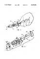
- FIG. 1is a perspective view showing the user grasping the syringe in the palm of his hand and pulling the plunger out of the barrel;
- FIG. 2is an exploded perspective view of the plunger showing the shank and the piston head;
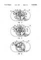
- FIG. 3is a cross sectional view of the shank, taken along the line 3--3 of FIG. 2, also showing the locking member;
- FIG. 4is a cross sectional view corresponding to FIG. 3 except with an alternative locking member
- FIG. 5is a cross sectional view of an alternative embodiment of the shank, and also an alternative locking member
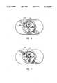
- FIG. 6is a cross sectional view of an alternate embodiment of the locking member cemented in place
- FIG. 7is a cross sectional view of an alternate embodiment of the locking member cemented in place
- FIG. 8is a cross sectional view of the piston head
- FIG. 9is a partial cross sectional view of the proximal end of the barrel with the plunger withdrawn approximately to its normal maximum position, short of complete withdrawal, showing the escape-proof feature and the glove-blocking feature;
- FIG. 10is cutaway view of a portion of the shank and locking member as indicated in FIG. 2;
- FIG. 11is a cross sectional view taken along the line 11--11 of FIG. 2.
- the syringe 10comprises a barrel 12 and a plunger 14.
- the barrel 12is preferably a one-piece molded plastic member, fashioned from a transparent plastic, and having a barrel wall 18.
- the barrelis open at its proximal end and closed at its distal end except for a relatively short tubular member 16 passing therethrough which serves as a means for attaching a cannula thereto.
- the barrelalso comprises a segmental flange 20 affixed to the proximal end of the barrel and extending radially outward. Although this flange is shown as being segmental, with ears extending outwardly at positions 180° apart, the flange could be completely circular if desired.
- the flangeserves as a means for supporting the fingers when forcing the plunger into the barrel or withdrawing the plunger from the barrel as shown in FIG. 1.
- the barrelalso has indicia 22 marked thereon which indicate the volume inside the barrel distal of the markings. These markings allow the user to fill the syringe with a prescribed amount of medication, or alternatively to determine when a prescribed amount of fluid has been aspirated from the patient.
- FIG. 2shows an exploded perspective view of the plunger 14 withdrawn from the barrel.
- the plungercomprises a shank 30 and a piston head 32, with a locking member 34, to be described later, affixed thereto.
- the shank 30is preferably fabricated as a one-piece molded item, fashioned from a rigid plastic.
- the shankis configured with a plurality of longitudinal and radially extending vanes.
- These vanesextend longitudinally over the major portion of the shank in order to provide the desired rigidity.
- Disc 60has a diameter slightly greater than the diameter of a phantom cylindrical volume that would be generated (swept out) by the vanes of the shank if the shank were rotated about its axis. Additionally, the diameter of disc 60 is slightly less than the inside diameter of the barrel 12, thus permitting it to move axially within the barrel. Disc 60 also serves as a portion of an escape-proof feature, to be described later.
- Disc 62has a diameter slightly less than the diameter of disc 60, being approximately the same as the diameter of the phantom cylindrical volume described above. Disc 62 serves as a bearing surface for the annular rim of piston head 32, to be described later.
- Disc 64has a diameter less than the diameter of disc 62 and serves to engage an internal groove 70 of piston head 32, as shown in FIG. 8.
- Groove 70has an outer diameter slightly greater than the diameter of disc 62.
- Piston head 32has a chamfered portion 72 (see FIG. 8) wherein the smaller diameter of the chamfer is less than the diameter of disc 62.
- piston head 32is fashioned from a resilient elastic material, such as neoprene rubber, and thus disc 62 can be inserted into groove 70 by expanding the chamfered portion, aided by tilting the disc 64 as it is inserted.
- disc 62serves as a bearing surface for the piston head 32.
- Annular surface 74 (FIG. 8) of the piston head 32is the surface against which disc 62 bears.
- disc 66is configured as an integral part of shank 30.
- Disc 66is fashioned at the proximal end of the shank and has a diameter somewhat greater than the diameter of the barrel.
- the primary purpose of disc 66is to serve as a support for the palm of the user to bear against when the shank is grasped so as to insert or retract the plunger with respect to the barrel.
- itmay serve as a support for the thumb of a user to bear against when pushing the plunger into the barrel, in which case the middle finger and index finger of the user bear against the distal surface of the flange 20.
- the proximal surface of disc 66is preferably serrated to aid in such usage.
- vanesare tapered at their proximal ends, as shown at 65 for a selected length. This serves to facilitate the grasping of the plunger by the user in the manner shown in FIG. 1, when the plunger is fully inserted into the barrel, permitting the thumb to exert force between the disc 66 and flange 20 to retract the plunger.
- piston head 32is equipped with annular ridges 76, 78, 80. These ridges have a diameter slightly greater than the internal diameter of the barrel, and thus, being resilient, serve to sealingly engage the barrel wall. Their purpose is to provide means whereby an at least partial vacuum can be established and maintained for an extended period of time in the barrel distal of the piston head upon retraction of the plunger, as well as providing a fluid-tight seal when the contents of the barrel are injected.
- End wall 82(see FIG. 8) of piston head 32 is preferably somewhat tapered so as to form a convex outer surface. The indicia markings on the barrel indicate the volume within the barrel distal of the piston head.
- FIG. 9shows a partial cross sectional view of the proximal end of the barrel and the plunger inserted therein, but being withdrawn to approximately its outermost position short of being completely withdrawn.
- disc 60has a diameter slightly greater than the internal diameter of annular ridge 90 which projects radially inward from the inside wall of barrel 10.
- the force necessary to continue the withdrawalbecomes greatly increased. This inhibits the user from inadvertently completely withdrawing the plunger.
- complete withdrawalcan be effected when necessary by applying sufficient force, aided by a slight tilting of the disc 60.
- the plungercan be initially inserted into the barrel.
- annular ridge 92positioned on the proximal face of the flange 20.
- this ridge 92when a gloved hand of a user is pressed against flange 20 during usage there is a tendency for a portion of the glove to be drawn into the barrel if there is a vacuum therein which tends to draw the plunger in.
- the presence of the ridge 92inhibits this drawing-in of the glove by spacing the fingers far enough away from the opening of the barrel to avoid the suction created by the vacuum.
- FIGS. 2, 3, 10, and 11One presently preferred embodiment is shown in FIGS. 2, 3, 10, and 11.
- this embodimentcomprises a relatively short elongate double channel 100, with each individual channel, such as 102 and 104, being configured as a block "U", and with the channels being interconnected by a connecting web 106 which connects the ends of mutually facing, but separated, respective side walls 108 and 110 of the two channels.
- Web 106is configured so as to space the facing walls 108 and 110 of the channels a distance apart slightly greater than the thickness of a vane, such as 40, of the plunger's shank, thus allowing the vane 40 to be positioned snugly between the facing walls 108 and 110.
- walls 108 and 110are configured to have a depth approximately the same as the radial dimension of vane 40, all as shown.
- vane 40fits snugly between the side walls 108 and 110.
- Respective webs 112 and 114 of the channelshave a width somewhat less than the radial dimension of the vanes 46 and 42.
- vane 40has a slot 120 fashioned therein, as shown best in FIGS. 10 and 11, which accepts web 106 snugly therein.
- the slot 120 in vane 40incorporates a projection 110 which projects over web 106, thus serving to lock channel 100 in place.
- side wall 122hereafter called the locking arm, of channel 104 is shown to project a sufficient distance outwardly and away from the vane 40 as to effect constructive interference with the peripheral wall 18 of the barrel. Due to the resilient nature of the channel 100, hereafter called the locking member, the constructive interference may be eliminated by pivoting locking arm 122 inward to a position such as that shown in phantom. Locking arm 122 pivots about its junction 126 with web 114. When so pivoted inward, the plunger with locking member or channel 100 may be inserted into the barrel.
- locking arm 122springs back into its unstressed position, again effecting constructive interference which prevents the plunger from being pulled back into the barrel.
- sidewall 124may also be configured as a locking arm so as to provide constructive interference with the peripheral barrel wall simply by extending its dimension as was done for locking arm 122, as shown in FIG. 4. This variation may be preferred by some users as it provides a double locking feature.
- pivoting actionmay be enhanced by providing a slight relief cutout 126 at the junction of the locking arm 122 and web 114, as depicted.
- a plurality of slots 120 on vane 40could be provided, each having a locking member so as to permit the plunger to be locked at any location along the plunger.
- the embodiment described aboveutilizes a plunger with a shank having four vanes.
- Another embodiment utilizing a shank having three vanesis depicted in FIG. 5.
- the locking member 140is configured as a channel having a projecting arm 142, hereafter called a locking arm which serves the same function as locking arm 122 of the previous embodiment of FIG. 3.
- Locking arm 142pivots about a junction 143 which comprises the junction of locking arm 142 with sidewall 144. In its unstressed position locking arm 142 projects outwardly sufficiently far as to provide constructive interference with peripheral wall 18 of the barrel, as noted, when the plunger is sufficiently withdrawn.
- a self-locking featureis provided similar to the other embodiment.
- Unlockingis effected by pivoting locking arm 142 inward to a position as noted by the phantom lines.
- Locking member 140is affixed to vane 50 of the shank in the same manner as locking member 100 of the previous embodiment. Alternatively, locking member 140 may be cemented to vane 50.
- the inventionteaches the use of any locking member that comprises a resilient locking member attached to the shank of a syringe plunger, and wherein the locking member is configured to pivot into the volume of space of the syringe barrel when the locking arm is pivoted inward by a user, and wherein the locking arm reverts back to its unstressed locking position when pulled outside of the barrel.
Landscapes
- Health & Medical Sciences (AREA)
- Vascular Medicine (AREA)
- Engineering & Computer Science (AREA)
- Anesthesiology (AREA)
- Biomedical Technology (AREA)
- Heart & Thoracic Surgery (AREA)
- Hematology (AREA)
- Life Sciences & Earth Sciences (AREA)
- Animal Behavior & Ethology (AREA)
- General Health & Medical Sciences (AREA)
- Public Health (AREA)
- Veterinary Medicine (AREA)
- Infusion, Injection, And Reservoir Apparatuses (AREA)
Abstract
Description
Claims (14)
Priority Applications (3)
| Application Number | Priority Date | Filing Date | Title |
|---|---|---|---|
| US07/792,203US5215536A (en) | 1991-11-13 | 1991-11-13 | Self-locking control syringe |
| AU31378/93AAU3137893A (en) | 1991-11-13 | 1992-11-13 | Self-locking control syringe |
| PCT/US1992/009862WO1993009827A1 (en) | 1991-11-13 | 1992-11-13 | Self-locking control syringe |
Applications Claiming Priority (1)
| Application Number | Priority Date | Filing Date | Title |
|---|---|---|---|
| US07/792,203US5215536A (en) | 1991-11-13 | 1991-11-13 | Self-locking control syringe |
Publications (1)
| Publication Number | Publication Date |
|---|---|
| US5215536Atrue US5215536A (en) | 1993-06-01 |
Family
ID=25156113
Family Applications (1)
| Application Number | Title | Priority Date | Filing Date |
|---|---|---|---|
| US07/792,203Expired - LifetimeUS5215536A (en) | 1991-11-13 | 1991-11-13 | Self-locking control syringe |
Country Status (3)
| Country | Link |
|---|---|
| US (1) | US5215536A (en) |
| AU (1) | AU3137893A (en) |
| WO (1) | WO1993009827A1 (en) |
Cited By (70)
| Publication number | Priority date | Publication date | Assignee | Title |
|---|---|---|---|---|
| US5338311A (en) | 1993-08-23 | 1994-08-16 | Mahurkar Sakharam D | Hypodermic needle assembly |
| US5377879A (en)* | 1993-12-22 | 1995-01-03 | Isaacs; Linda R. F. | Measuring spoon |
| US5401249A (en)* | 1993-06-07 | 1995-03-28 | Shields; Jack W. | Safely disposable, non-reusable injection device |
| US5485853A (en)* | 1994-04-28 | 1996-01-23 | Stubbs; George | Apparatus for withdrawing fluid or tissue from a patient's body |
| EP0709106A3 (en)* | 1994-09-30 | 1996-09-11 | Takeda Chemical Industries Ltd | Syringe |
| US5558637A (en)* | 1993-10-13 | 1996-09-24 | Leiras Oy | Implant injection device |
| US5895376A (en)* | 1996-10-23 | 1999-04-20 | Mayo Foundation For Medical Education And Research | Hemostasis valve, system and assembly |
| US5989219A (en)* | 1998-01-23 | 1999-11-23 | Becton, Dickinson And Company | Single-use syringe |
| US6142978A (en)* | 2000-01-24 | 2000-11-07 | Bracco Diagnostics, Inc. | Self-aligning plunger rod |
| US6190363B1 (en)* | 2000-01-24 | 2001-02-20 | Bracco Diagnostics, Inc. | Self-aligning plunger rod |
| US6206859B1 (en)* | 2000-01-24 | 2001-03-27 | Bracco Diagnostics, Inc. | Self-aligning plunger rod |
| US20020087125A1 (en)* | 1997-03-21 | 2002-07-04 | Pokorney James L. | High pressure syringe |
| USD460820S1 (en) | 2000-12-04 | 2002-07-23 | Bracco Diagnostics Inc. | Ellipsoidal syringe barrel |
| USD461243S1 (en) | 2000-12-04 | 2002-08-06 | Bracco Diagnostics Inc. | Ellipsoidal syringe barrel |
| US20020191487A1 (en)* | 2000-10-25 | 2002-12-19 | Kyphon Inc. | Systems and methods for mixing and transferring flowable materials |
| US20030195524A1 (en)* | 2002-04-12 | 2003-10-16 | Gil Barner | Body tissue aspiration cannula |
| WO2003026720A3 (en)* | 2001-09-24 | 2003-11-13 | Becton Dickinson Co | Single use syringe and plunger rod locking device therefor |
| US6652493B1 (en) | 2000-07-05 | 2003-11-25 | Animas Corporation | Infusion pump syringe |
| US20040024357A1 (en)* | 2001-09-24 | 2004-02-05 | Pelkey Brian J. | Single use syringe and plunger rod locking device therefor |
| US20040059294A1 (en)* | 2002-09-25 | 2004-03-25 | Pelkey Brian J. | Single use syringe and plunger rod locking device therefor |
| US20040073166A1 (en)* | 2001-09-24 | 2004-04-15 | Lau Steven Choon Meng | Single use syringe and plunger rod locking device therefor |
| US20040172008A1 (en)* | 2002-11-19 | 2004-09-02 | Gmp/Cardiac Care, Inc. | Hemostasis valve and method of using a hemostasis valve |
| US6790197B2 (en) | 2002-09-25 | 2004-09-14 | Becton Dickinson And Company | Single use syringe and plunger rod locking device therefor |
| US20050080382A1 (en)* | 2003-10-14 | 2005-04-14 | Hsin-Po Hsieh | Safety syringe |
| US20050100424A1 (en)* | 1996-04-10 | 2005-05-12 | Distasio Robert J. | Locking nut, bolt and clip systems and assemblies |
| US20050154353A1 (en)* | 2004-01-09 | 2005-07-14 | Alheidt Thomas A. | Positive displacement flush syringe |
| WO2006012280A1 (en)* | 2004-06-29 | 2006-02-02 | Becton, Dickinson And Company | Single-use syringe |
| US20060100591A1 (en)* | 2002-10-11 | 2006-05-11 | Alheidt Thomas A | Flush syringe having compressible plunger |
| US20060178638A1 (en)* | 2004-12-03 | 2006-08-10 | Reynolds David L | Device and method for pharmaceutical mixing and delivery |
| USD531500S1 (en) | 2005-05-12 | 2006-11-07 | The Procter & Gamble Company | Ornamentation for container element |
| US20070043376A1 (en)* | 2003-02-21 | 2007-02-22 | Osteobiologics, Inc. | Bone and cartilage implant delivery device |
| US20070073226A1 (en)* | 2005-09-23 | 2007-03-29 | John Polidoro | Syringe |
| US20070088293A1 (en)* | 2005-07-06 | 2007-04-19 | Fangrow Thomas F Jr | Medical connector with closeable male luer |
| US20070129686A1 (en)* | 2003-09-17 | 2007-06-07 | Dali Medical Devices Ltd. | Automatic injection device |
| USD550099S1 (en) | 2004-04-22 | 2007-09-04 | The Procter & Gamble Company | Bottle |
| US20070225656A1 (en)* | 2006-03-24 | 2007-09-27 | Hoyle John D Jr | Dosage Control Syringe |
| US20070255227A1 (en)* | 2006-04-27 | 2007-11-01 | Haase James M | Methods and apparatus for refilling an infusion device |
| US20080082055A1 (en)* | 2006-09-29 | 2008-04-03 | Tyco Healthcare Group Lp | Detachable plunger rod syringe |
| US20080124397A1 (en)* | 1999-12-29 | 2008-05-29 | Regeneration Technologies, Inc. | System For Reconstituting Pastes And Methods Of Using Same |
| WO2008057976A3 (en)* | 2006-11-03 | 2008-08-07 | Avanca Medical Devices Inc | Multiple dose syringes |
| US20080221529A1 (en)* | 2007-03-05 | 2008-09-11 | Kiehne Bruce L | Syringe with rear plunger lock |
| US20090204076A1 (en)* | 2003-02-03 | 2009-08-13 | Barry Peter Liversidge | Medical Injector |
| US20100036318A1 (en)* | 2006-10-19 | 2010-02-11 | Elcam Medical Agricultural Cooperative Association | Automatic injection device |
| US20100174236A1 (en)* | 2008-11-26 | 2010-07-08 | Steven Burns | Single-use auto-disable syringe |
| US20110049181A1 (en)* | 2008-04-18 | 2011-03-03 | Peter Lutz | Dispensing device, kit containing the device, and method of operating the device |
| US7901382B2 (en) | 2003-09-17 | 2011-03-08 | Dali Medical Devices, Ltd. | Automatic needle device |
| US7985216B2 (en) | 2004-03-16 | 2011-07-26 | Dali Medical Devices Ltd. | Medicinal container engagement and automatic needle device |
| CN102753275A (en)* | 2010-02-12 | 2012-10-24 | 药物混合系统股份公司 | Discharge device having a locking element |
| US20130123712A1 (en)* | 2011-11-11 | 2013-05-16 | Becton, Dickinson And Company | Plunger Rod Retaining Anchors |
| US8485986B2 (en) | 2010-06-08 | 2013-07-16 | Merit Medical Systems, Inc. | Biopsy collection device and related methods |
| WO2013132192A1 (en) | 2012-03-08 | 2013-09-12 | Stemcis | Syringe for medical applications |
| US20140188052A1 (en)* | 2012-12-28 | 2014-07-03 | Daikyo Seiko, Ltd. | Medical syringe |
| US8992477B2 (en) | 2011-01-24 | 2015-03-31 | Elcam Agricultural Cooperative Association Ltd. | Injector |
| US20150105735A1 (en)* | 2013-10-16 | 2015-04-16 | Regeneron Pharmaceuticals, Inc. | Syringe pistons, systems and methods |
| US20150164309A1 (en)* | 2013-12-17 | 2015-06-18 | Biovision Technologies, Llc | Surgical device for performing a sphenopalatine ganglion block procedure |
| US9186463B2 (en) | 2010-06-30 | 2015-11-17 | John D. Hoyle, Jr. | Dosage control syringe |
| US9248266B2 (en) | 2013-12-17 | 2016-02-02 | Biovision Technologies, Llc | Method of performing a sphenopalatine ganglion block procedure |
| USD750774S1 (en)* | 2013-04-19 | 2016-03-01 | Transcoject Gmbh | Syringe plunger |
| US20160271375A1 (en)* | 2013-12-17 | 2016-09-22 | Biovision Technologies, Inc. | Methods for treating sinus diseases |
| US9468745B2 (en) | 2011-01-05 | 2016-10-18 | Spotlight Technology Partners Llc | Apparatus and methods for inflating and deflating balloon catheters |
| USD772406S1 (en) | 2014-12-16 | 2016-11-22 | Biovision Technologies, Llc | Surgical device |
| US20170028135A1 (en)* | 2014-04-14 | 2017-02-02 | Swedish Orphan Biovitrum Ab (Publ) | Syringe plunger rod |
| US9694163B2 (en) | 2013-12-17 | 2017-07-04 | Biovision Technologies, Llc | Surgical device for performing a sphenopalatine ganglion block procedure |
| USD804651S1 (en) | 2017-01-10 | 2017-12-05 | Howard Loonan | Syringe |
| US20180078707A1 (en)* | 2016-09-20 | 2018-03-22 | Howard Loonan | Syringe with position locking plunger |
| US10525240B1 (en) | 2018-06-28 | 2020-01-07 | Sandler Scientific LLC | Sino-nasal rinse delivery device with agitation, flow-control and integrated medication management system |
| US11229747B2 (en)* | 2014-02-03 | 2022-01-25 | Unl Holdings Llc | Expanding plunger rods for syringes |
| WO2023038988A1 (en)* | 2021-09-07 | 2023-03-16 | Bree Elizabeth Marie | Linking structure and container assembly to facilitate liquid transfer from a donor container to a recipient container |
| EP4393530A1 (en) | 2022-12-26 | 2024-07-03 | Estar Technologies Ltd | Syringe device plunger with axially extendable detents and methods of using and processes of manufacturing the same |
| WO2025106851A1 (en)* | 2023-11-16 | 2025-05-22 | Inari Medical, Inc. | Automatic locking and unlocking vacuum syringes, and associated systems and methods |
Families Citing this family (4)
| Publication number | Priority date | Publication date | Assignee | Title |
|---|---|---|---|---|
| US6176846B1 (en) | 1999-03-22 | 2001-01-23 | Bracco Diagnostics, Inc. | Plunger rod |
| US6030367A (en)* | 1999-03-22 | 2000-02-29 | Bracco Research | Plunger rod |
| US20070049872A1 (en)* | 2005-07-01 | 2007-03-01 | Philip Watts | Syringe clip |
| USD690807S1 (en) | 2011-11-11 | 2013-10-01 | Becton, Dickinson And Company | Plunger rod having retaining anchors |
Citations (18)
| Publication number | Priority date | Publication date | Assignee | Title |
|---|---|---|---|---|
| US3747812A (en)* | 1971-10-21 | 1973-07-24 | Medical Concepts Inc | Syringe |
| US3951146A (en)* | 1972-11-01 | 1976-04-20 | Arias Marcelo Chiquiar | Disposable self-destructible syringes which render themselves unreusable |
| US4333458A (en)* | 1981-02-09 | 1982-06-08 | Sterling Drug Inc. | Self-aspirating syringe with positively engaged locking collet |
| US4386606A (en)* | 1979-12-26 | 1983-06-07 | Waters Instruments, Inc. | Syringe lock |
| US4610672A (en)* | 1985-06-10 | 1986-09-09 | Sherwood Medical Company | Syringe locking device |
| US4711637A (en)* | 1986-02-04 | 1987-12-08 | Baxter Travenol Laboratories, Inc. | Syringe lock |
| US4744791A (en)* | 1986-12-18 | 1988-05-17 | Georges Egolf | Syringe with automatic piston retraction |
| US4758232A (en)* | 1987-09-08 | 1988-07-19 | Chak Choi K | Suction syringe with an automatic locking means |
| WO1989002287A1 (en)* | 1987-09-18 | 1989-03-23 | Free Michael J | Single use disposable syringe |
| US4840616A (en)* | 1987-02-27 | 1989-06-20 | Bev-Cap Plastics Pty. Ltd. | Syringe hypodermic needle |
| WO1989009331A1 (en)* | 1988-04-02 | 1989-10-05 | Robert Bosch Gmbh | Learning control process for an internal combustion engine and device therefor |
| US4890626A (en)* | 1986-08-19 | 1990-01-02 | Wang Ko P | Removable locking device for use with syringes |
| US4925449A (en)* | 1988-01-11 | 1990-05-15 | Applied Vascular Devices | Manually driven syringe |
| US4929238A (en)* | 1988-11-23 | 1990-05-29 | Coeur Laboratories, Inc. | Multi-pressure injector device |
| US4961728A (en)* | 1988-12-30 | 1990-10-09 | Becton, Dickinson And Company | Single-use syringe having misuse resistant features |
| US4973310A (en)* | 1988-12-30 | 1990-11-27 | Becton, Dickinson And Company | Single-use syringe |
| WO1991001768A1 (en)* | 1989-08-07 | 1991-02-21 | Alan Chris Allison | Insertable element for preventing reuse of plastic syringes |
| WO1991012039A1 (en)* | 1990-02-15 | 1991-08-22 | Alan Henry Polyblank | Non-reusable syringe |
- 1991
- 1991-11-13USUS07/792,203patent/US5215536A/ennot_activeExpired - Lifetime
- 1992
- 1992-11-13AUAU31378/93Apatent/AU3137893A/ennot_activeAbandoned
- 1992-11-13WOPCT/US1992/009862patent/WO1993009827A1/enactiveApplication Filing
Patent Citations (18)
| Publication number | Priority date | Publication date | Assignee | Title |
|---|---|---|---|---|
| US3747812A (en)* | 1971-10-21 | 1973-07-24 | Medical Concepts Inc | Syringe |
| US3951146A (en)* | 1972-11-01 | 1976-04-20 | Arias Marcelo Chiquiar | Disposable self-destructible syringes which render themselves unreusable |
| US4386606A (en)* | 1979-12-26 | 1983-06-07 | Waters Instruments, Inc. | Syringe lock |
| US4333458A (en)* | 1981-02-09 | 1982-06-08 | Sterling Drug Inc. | Self-aspirating syringe with positively engaged locking collet |
| US4610672A (en)* | 1985-06-10 | 1986-09-09 | Sherwood Medical Company | Syringe locking device |
| US4711637A (en)* | 1986-02-04 | 1987-12-08 | Baxter Travenol Laboratories, Inc. | Syringe lock |
| US4890626A (en)* | 1986-08-19 | 1990-01-02 | Wang Ko P | Removable locking device for use with syringes |
| US4744791A (en)* | 1986-12-18 | 1988-05-17 | Georges Egolf | Syringe with automatic piston retraction |
| US4840616A (en)* | 1987-02-27 | 1989-06-20 | Bev-Cap Plastics Pty. Ltd. | Syringe hypodermic needle |
| US4758232A (en)* | 1987-09-08 | 1988-07-19 | Chak Choi K | Suction syringe with an automatic locking means |
| WO1989002287A1 (en)* | 1987-09-18 | 1989-03-23 | Free Michael J | Single use disposable syringe |
| US4925449A (en)* | 1988-01-11 | 1990-05-15 | Applied Vascular Devices | Manually driven syringe |
| WO1989009331A1 (en)* | 1988-04-02 | 1989-10-05 | Robert Bosch Gmbh | Learning control process for an internal combustion engine and device therefor |
| US4929238A (en)* | 1988-11-23 | 1990-05-29 | Coeur Laboratories, Inc. | Multi-pressure injector device |
| US4961728A (en)* | 1988-12-30 | 1990-10-09 | Becton, Dickinson And Company | Single-use syringe having misuse resistant features |
| US4973310A (en)* | 1988-12-30 | 1990-11-27 | Becton, Dickinson And Company | Single-use syringe |
| WO1991001768A1 (en)* | 1989-08-07 | 1991-02-21 | Alan Chris Allison | Insertable element for preventing reuse of plastic syringes |
| WO1991012039A1 (en)* | 1990-02-15 | 1991-08-22 | Alan Henry Polyblank | Non-reusable syringe |
Cited By (125)
| Publication number | Priority date | Publication date | Assignee | Title |
|---|---|---|---|---|
| US5401249A (en)* | 1993-06-07 | 1995-03-28 | Shields; Jack W. | Safely disposable, non-reusable injection device |
| US5338311A (en) | 1993-08-23 | 1994-08-16 | Mahurkar Sakharam D | Hypodermic needle assembly |
| US5514100A (en) | 1993-08-23 | 1996-05-07 | Mahurkar; Sakharam D. | Hypodermic needle assembly |
| US5558637A (en)* | 1993-10-13 | 1996-09-24 | Leiras Oy | Implant injection device |
| US5377879A (en)* | 1993-12-22 | 1995-01-03 | Isaacs; Linda R. F. | Measuring spoon |
| US5485853A (en)* | 1994-04-28 | 1996-01-23 | Stubbs; George | Apparatus for withdrawing fluid or tissue from a patient's body |
| US5688252A (en)* | 1994-09-30 | 1997-11-18 | Takeda Chemical Industries, Ltd. | Syringe |
| EP0709106A3 (en)* | 1994-09-30 | 1996-09-11 | Takeda Chemical Industries Ltd | Syringe |
| US20050100424A1 (en)* | 1996-04-10 | 2005-05-12 | Distasio Robert J. | Locking nut, bolt and clip systems and assemblies |
| US5895376A (en)* | 1996-10-23 | 1999-04-20 | Mayo Foundation For Medical Education And Research | Hemostasis valve, system and assembly |
| US6221057B1 (en) | 1996-10-23 | 2001-04-24 | Mayo Foundation For Medical Education And Research | Hemostasis valve, system and assembly |
| US7022112B2 (en) | 1997-03-21 | 2006-04-04 | Pokorney James L | High pressure syringe |
| US20020087125A1 (en)* | 1997-03-21 | 2002-07-04 | Pokorney James L. | High pressure syringe |
| US5989219A (en)* | 1998-01-23 | 1999-11-23 | Becton, Dickinson And Company | Single-use syringe |
| US20080124397A1 (en)* | 1999-12-29 | 2008-05-29 | Regeneration Technologies, Inc. | System For Reconstituting Pastes And Methods Of Using Same |
| US7824702B2 (en) | 1999-12-29 | 2010-11-02 | Rti Biologics, Inc. | Composition for making a bone paste |
| US6142978A (en)* | 2000-01-24 | 2000-11-07 | Bracco Diagnostics, Inc. | Self-aligning plunger rod |
| US6190363B1 (en)* | 2000-01-24 | 2001-02-20 | Bracco Diagnostics, Inc. | Self-aligning plunger rod |
| US6206859B1 (en)* | 2000-01-24 | 2001-03-27 | Bracco Diagnostics, Inc. | Self-aligning plunger rod |
| US6652493B1 (en) | 2000-07-05 | 2003-11-25 | Animas Corporation | Infusion pump syringe |
| US20060187747A1 (en)* | 2000-10-25 | 2006-08-24 | Kyphon Inc. | Methods for mixing and transferring flowable materials |
| US20070121422A1 (en)* | 2000-10-25 | 2007-05-31 | Kyphon Inc. | Methods for mixing and transferring flowable materials |
| US7278778B2 (en) | 2000-10-25 | 2007-10-09 | Kyphon Inc. | System for mixing and transferring flowable materials |
| US7160020B2 (en) | 2000-10-25 | 2007-01-09 | Kyphon Inc. | Methods for mixing and transferring flowable materials |
| US20020191487A1 (en)* | 2000-10-25 | 2002-12-19 | Kyphon Inc. | Systems and methods for mixing and transferring flowable materials |
| USD461243S1 (en) | 2000-12-04 | 2002-08-06 | Bracco Diagnostics Inc. | Ellipsoidal syringe barrel |
| USD460820S1 (en) | 2000-12-04 | 2002-07-23 | Bracco Diagnostics Inc. | Ellipsoidal syringe barrel |
| AP1877A (en)* | 2001-09-24 | 2008-08-13 | Becton Dickinson Co | Single use syringe and plunger rod locking device therefor. |
| US7052482B2 (en)* | 2001-09-24 | 2006-05-30 | Becton, Dickinson And Company | Single use syringe and plunger rod locking device therefor |
| WO2003026720A3 (en)* | 2001-09-24 | 2003-11-13 | Becton Dickinson Co | Single use syringe and plunger rod locking device therefor |
| US20040024357A1 (en)* | 2001-09-24 | 2004-02-05 | Pelkey Brian J. | Single use syringe and plunger rod locking device therefor |
| US6986756B2 (en) | 2001-09-24 | 2006-01-17 | Becton, Dickinson And Company | Single use syringe and plunger rod locking device therefor |
| US6991618B2 (en)* | 2001-09-24 | 2006-01-31 | Becton Dickinson And Company | Single use syringe and plunger rod locking device therefor |
| CN100446819C (en)* | 2001-09-24 | 2008-12-31 | 贝克顿迪肯森公司 | Single use syringe and plunger rod locking device therefor |
| US20040073166A1 (en)* | 2001-09-24 | 2004-04-15 | Lau Steven Choon Meng | Single use syringe and plunger rod locking device therefor |
| US20030195524A1 (en)* | 2002-04-12 | 2003-10-16 | Gil Barner | Body tissue aspiration cannula |
| US20040059294A1 (en)* | 2002-09-25 | 2004-03-25 | Pelkey Brian J. | Single use syringe and plunger rod locking device therefor |
| US6790197B2 (en) | 2002-09-25 | 2004-09-14 | Becton Dickinson And Company | Single use syringe and plunger rod locking device therefor |
| US20050187518A1 (en)* | 2002-09-25 | 2005-08-25 | Pelkey Brian J. | Single use syringe and plunger rod locking device therefor |
| US20060100591A1 (en)* | 2002-10-11 | 2006-05-11 | Alheidt Thomas A | Flush syringe having compressible plunger |
| US9333301B2 (en) | 2002-10-11 | 2016-05-10 | Becton, Dickinson And Company | Flush syringe having compressible plunger |
| US20040172008A1 (en)* | 2002-11-19 | 2004-09-02 | Gmp/Cardiac Care, Inc. | Hemostasis valve and method of using a hemostasis valve |
| US20090204076A1 (en)* | 2003-02-03 | 2009-08-13 | Barry Peter Liversidge | Medical Injector |
| US20070043376A1 (en)* | 2003-02-21 | 2007-02-22 | Osteobiologics, Inc. | Bone and cartilage implant delivery device |
| US8376998B2 (en) | 2003-09-17 | 2013-02-19 | Elcam Medical Agricultural Cooperative Association Ltd. | Automatic injection device |
| US8328765B2 (en) | 2003-09-17 | 2012-12-11 | Dali Medical Devices Ltd. | Automatic needle device |
| EP2650033A2 (en) | 2003-09-17 | 2013-10-16 | Elcam Medical Agricultural Cooperative Association Ltd. | Automatic injection device |
| US20070129686A1 (en)* | 2003-09-17 | 2007-06-07 | Dali Medical Devices Ltd. | Automatic injection device |
| US7901382B2 (en) | 2003-09-17 | 2011-03-08 | Dali Medical Devices, Ltd. | Automatic needle device |
| US20110152783A1 (en)* | 2003-09-17 | 2011-06-23 | Dali Medical Devices Ltd. | Automatic needle device |
| US11623051B2 (en) | 2003-09-17 | 2023-04-11 | E3D Agricultural Cooperative Association Ltd. | Automatic injection device |
| US6979314B2 (en)* | 2003-10-14 | 2005-12-27 | Syriteck Medical Devices Co., Ltd. | Safety syringe |
| US20050080382A1 (en)* | 2003-10-14 | 2005-04-14 | Hsin-Po Hsieh | Safety syringe |
| US20080262439A1 (en)* | 2004-01-09 | 2008-10-23 | Becton Dickinson And Company | Positive Displacement Flush Syringe |
| US20080021414A1 (en)* | 2004-01-09 | 2008-01-24 | Becton Dickinson And Company | Positive displacement flush syringe |
| US20050154353A1 (en)* | 2004-01-09 | 2005-07-14 | Alheidt Thomas A. | Positive displacement flush syringe |
| US8574202B2 (en) | 2004-01-09 | 2013-11-05 | Becton, Dickinson And Company | Positive displacement flush syringe |
| US7985216B2 (en) | 2004-03-16 | 2011-07-26 | Dali Medical Devices Ltd. | Medicinal container engagement and automatic needle device |
| USD550099S1 (en) | 2004-04-22 | 2007-09-04 | The Procter & Gamble Company | Bottle |
| US7740610B2 (en) | 2004-06-29 | 2010-06-22 | Becton, Dickinson And Company | Single-use syringe |
| WO2006012280A1 (en)* | 2004-06-29 | 2006-02-02 | Becton, Dickinson And Company | Single-use syringe |
| US20060079839A1 (en)* | 2004-06-29 | 2006-04-13 | Becton, Dickinson And Company | Single-use syringe |
| US20080154196A1 (en)* | 2004-06-29 | 2008-06-26 | Becton, Dickinson And Company | Single-Use Syringe |
| US20060178641A1 (en)* | 2004-12-03 | 2006-08-10 | Reynolds David L | Extensible plunger rod for pharmaceutical delivery device |
| US20060178638A1 (en)* | 2004-12-03 | 2006-08-10 | Reynolds David L | Device and method for pharmaceutical mixing and delivery |
| US20060178644A1 (en)* | 2004-12-03 | 2006-08-10 | Reynolds David L | Pharmaceutical cartridge assembly and method of filling same |
| USD531500S1 (en) | 2005-05-12 | 2006-11-07 | The Procter & Gamble Company | Ornamentation for container element |
| US20070088293A1 (en)* | 2005-07-06 | 2007-04-19 | Fangrow Thomas F Jr | Medical connector with closeable male luer |
| US20070073226A1 (en)* | 2005-09-23 | 2007-03-29 | John Polidoro | Syringe |
| US7470259B2 (en) | 2006-03-24 | 2008-12-30 | Hoyle Jr John D | Dosage control syringe |
| US20070225656A1 (en)* | 2006-03-24 | 2007-09-27 | Hoyle John D Jr | Dosage Control Syringe |
| US20070255227A1 (en)* | 2006-04-27 | 2007-11-01 | Haase James M | Methods and apparatus for refilling an infusion device |
| US8038656B2 (en) | 2006-09-29 | 2011-10-18 | Tyco Healthcare Group Lp | Detachable plunger rod syringe |
| US20080082055A1 (en)* | 2006-09-29 | 2008-04-03 | Tyco Healthcare Group Lp | Detachable plunger rod syringe |
| US9345831B2 (en) | 2006-10-19 | 2016-05-24 | E3D Agricultural Cooperative Association Ltd | Automatic injection device |
| US20100036318A1 (en)* | 2006-10-19 | 2010-02-11 | Elcam Medical Agricultural Cooperative Association | Automatic injection device |
| WO2008057976A3 (en)* | 2006-11-03 | 2008-08-07 | Avanca Medical Devices Inc | Multiple dose syringes |
| US20080221529A1 (en)* | 2007-03-05 | 2008-09-11 | Kiehne Bruce L | Syringe with rear plunger lock |
| US8469233B2 (en)* | 2008-04-18 | 2013-06-25 | Kuros Biosurgery Ag | Dispensing device, kit containing the device, and method of operating the device |
| US20110049181A1 (en)* | 2008-04-18 | 2011-03-03 | Peter Lutz | Dispensing device, kit containing the device, and method of operating the device |
| US8287491B2 (en) | 2008-11-26 | 2012-10-16 | Becton, Dickinson And Company | Single-use auto-disable syringe |
| US20100174236A1 (en)* | 2008-11-26 | 2010-07-08 | Steven Burns | Single-use auto-disable syringe |
| US9205205B2 (en) | 2008-11-26 | 2015-12-08 | Becton, Dickinson And Company | Single-use auto-disable syringe |
| CN102753275A (en)* | 2010-02-12 | 2012-10-24 | 药物混合系统股份公司 | Discharge device having a locking element |
| CN102753275B (en)* | 2010-02-12 | 2015-05-13 | 药物混合系统股份公司 | Discharge device having a locking element |
| US8485986B2 (en) | 2010-06-08 | 2013-07-16 | Merit Medical Systems, Inc. | Biopsy collection device and related methods |
| US9186463B2 (en) | 2010-06-30 | 2015-11-17 | John D. Hoyle, Jr. | Dosage control syringe |
| US9468745B2 (en) | 2011-01-05 | 2016-10-18 | Spotlight Technology Partners Llc | Apparatus and methods for inflating and deflating balloon catheters |
| US8992477B2 (en) | 2011-01-24 | 2015-03-31 | Elcam Agricultural Cooperative Association Ltd. | Injector |
| US12420029B2 (en) | 2011-01-24 | 2025-09-23 | E3D Agricultural Cooperative Association Ltd. | Injector |
| US10806867B2 (en) | 2011-01-24 | 2020-10-20 | E3D Agricultural Cooperative Association Ltd. | Injector |
| US20130123712A1 (en)* | 2011-11-11 | 2013-05-16 | Becton, Dickinson And Company | Plunger Rod Retaining Anchors |
| US20150105754A1 (en)* | 2012-03-08 | 2015-04-16 | Stemcis | Syringe for medical applications |
| WO2013132192A1 (en) | 2012-03-08 | 2013-09-12 | Stemcis | Syringe for medical applications |
| US9545464B2 (en)* | 2012-03-08 | 2017-01-17 | Stemcis | Syringe with ratcheting operating rod and lockable plunger head |
| US9511192B2 (en)* | 2012-12-28 | 2016-12-06 | Daikyo Seiko, Ltd. | Medical syringe |
| US20140188052A1 (en)* | 2012-12-28 | 2014-07-03 | Daikyo Seiko, Ltd. | Medical syringe |
| USD750774S1 (en)* | 2013-04-19 | 2016-03-01 | Transcoject Gmbh | Syringe plunger |
| US20150105735A1 (en)* | 2013-10-16 | 2015-04-16 | Regeneron Pharmaceuticals, Inc. | Syringe pistons, systems and methods |
| US10016580B2 (en)* | 2013-12-17 | 2018-07-10 | Biovision Technologies, Llc | Methods for treating sinus diseases |
| US20160271375A1 (en)* | 2013-12-17 | 2016-09-22 | Biovision Technologies, Inc. | Methods for treating sinus diseases |
| US9510743B2 (en) | 2013-12-17 | 2016-12-06 | Biovision Technologies, Llc | Stabilized surgical device for performing a sphenopalatine ganglion block procedure |
| US9516995B2 (en)* | 2013-12-17 | 2016-12-13 | Biovision Technologies, Llc | Surgical device for performing a sphenopalatine ganglion block procedure |
| US9694163B2 (en) | 2013-12-17 | 2017-07-04 | Biovision Technologies, Llc | Surgical device for performing a sphenopalatine ganglion block procedure |
| US9248266B2 (en) | 2013-12-17 | 2016-02-02 | Biovision Technologies, Llc | Method of performing a sphenopalatine ganglion block procedure |
| US9839347B2 (en) | 2013-12-17 | 2017-12-12 | Biovision Technologies Llc | Method of performing a sphenopalatine ganglion block procedure |
| US11058855B2 (en) | 2013-12-17 | 2021-07-13 | Biovision Technologies, Llc | Surgical device for performing a sphenopalatine ganglion block procedure |
| US20150164309A1 (en)* | 2013-12-17 | 2015-06-18 | Biovision Technologies, Llc | Surgical device for performing a sphenopalatine ganglion block procedure |
| US10046143B2 (en) | 2013-12-17 | 2018-08-14 | Biovision Technologies Llc | Surgical device for performing a sphenopalatine ganglion block procedure |
| US10420459B2 (en) | 2013-12-17 | 2019-09-24 | Biovision Technologies, Llc | Method of performing a sphenopalatine ganglion block procedure |
| US10589072B2 (en) | 2013-12-17 | 2020-03-17 | Biovision Technologies, Llc | Methods for treating sinus diseases |
| US11229747B2 (en)* | 2014-02-03 | 2022-01-25 | Unl Holdings Llc | Expanding plunger rods for syringes |
| US20170028135A1 (en)* | 2014-04-14 | 2017-02-02 | Swedish Orphan Biovitrum Ab (Publ) | Syringe plunger rod |
| US11191903B2 (en)* | 2014-04-14 | 2021-12-07 | Swedish Orphan Biovitrum Ab (Publ) | Syringe plunger rod |
| USD772406S1 (en) | 2014-12-16 | 2016-11-22 | Biovision Technologies, Llc | Surgical device |
| US10857301B2 (en)* | 2016-09-20 | 2020-12-08 | Endospace Corporation | Syringe with position locking plunger |
| US20180078707A1 (en)* | 2016-09-20 | 2018-03-22 | Howard Loonan | Syringe with position locking plunger |
| USD804651S1 (en) | 2017-01-10 | 2017-12-05 | Howard Loonan | Syringe |
| US10525240B1 (en) | 2018-06-28 | 2020-01-07 | Sandler Scientific LLC | Sino-nasal rinse delivery device with agitation, flow-control and integrated medication management system |
| WO2023038988A1 (en)* | 2021-09-07 | 2023-03-16 | Bree Elizabeth Marie | Linking structure and container assembly to facilitate liquid transfer from a donor container to a recipient container |
| CN116745215A (en)* | 2021-09-07 | 2023-09-12 | 伊丽莎白·玛丽·布里 | Linking structures and container components that facilitate the transfer of liquid from a donor container to a recipient container |
| CN116745215B (en)* | 2021-09-07 | 2024-02-20 | 安妮·玛丽·布里 | Coupling structure and container assembly for facilitating transfer of liquid from a donor container to a recipient container |
| US11952168B2 (en) | 2021-09-07 | 2024-04-09 | Anne Marie Bree | Linking structure and container assembly to facilitate liquid transfer from a donor container to a recipient container |
| EP4393530A1 (en) | 2022-12-26 | 2024-07-03 | Estar Technologies Ltd | Syringe device plunger with axially extendable detents and methods of using and processes of manufacturing the same |
| WO2025106851A1 (en)* | 2023-11-16 | 2025-05-22 | Inari Medical, Inc. | Automatic locking and unlocking vacuum syringes, and associated systems and methods |
Also Published As
| Publication number | Publication date |
|---|---|
| AU3137893A (en) | 1993-06-15 |
| WO1993009827A1 (en) | 1993-05-27 |
Similar Documents
| Publication | Publication Date | Title |
|---|---|---|
| US5215536A (en) | Self-locking control syringe | |
| EP0916354B1 (en) | Single-use safety syringe | |
| US6206856B1 (en) | Safety syringe | |
| US6106500A (en) | Hypodermic needle assembly | |
| JP2921562B2 (en) | Needle shield assembly | |
| US6261259B1 (en) | Needle removal and containment device and method of using same | |
| CA2384597C (en) | Improved retractable needle single use safety syringe | |
| EP0436646B1 (en) | Guarded winged needle assembly | |
| CA2464854C (en) | Medical device having releasable retainer | |
| US5219339A (en) | Single use medical needle | |
| US8663169B2 (en) | Needle for bloodless IV | |
| US5643222A (en) | Hypodermic needle assembly | |
| US6860872B2 (en) | Safety syringe/catheter | |
| JPH05261153A (en) | Throw-away self-shielded hypodermic syringe | |
| JPH05508568A (en) | Improved parenteral administration device | |
| JPH10127767A (en) | Needle assembly provided with needle barrier which can be operated by one hand | |
| EP1704888A1 (en) | Retractable needle single use safety syringe |
Legal Events
| Date | Code | Title | Description |
|---|---|---|---|
| AS | Assignment | Owner name:MERIT MEDICAL SYSTEMS, INC., UTAH Free format text:ASSIGNMENT OF ASSIGNORS INTEREST.;ASSIGNORS:LAMPROPOULOS, FRED P.;PADILLA, WILLIAM;NELSON, ARLIN D.;REEL/FRAME:005980/0388 Effective date:19911210 | |
| STCF | Information on status: patent grant | Free format text:PATENTED CASE | |
| CC | Certificate of correction | ||
| AS | Assignment | Owner name:ZIONS FIRST NATIONAL BANK, UTAH Free format text:SECURITY INTEREST;ASSIGNOR:MERIT MEDICAL SYSTEMS, INC.;REEL/FRAME:007709/0949 Effective date:19951010 | |
| FEPP | Fee payment procedure | Free format text:PAYOR NUMBER ASSIGNED (ORIGINAL EVENT CODE: ASPN); ENTITY STATUS OF PATENT OWNER: LARGE ENTITY Free format text:PAT HLDR NO LONGER CLAIMS SMALL ENT STAT AS SMALL BUSINESS (ORIGINAL EVENT CODE: LSM2); ENTITY STATUS OF PATENT OWNER: LARGE ENTITY | |
| FPAY | Fee payment | Year of fee payment:4 | |
| FEPP | Fee payment procedure | Free format text:PAYER NUMBER DE-ASSIGNED (ORIGINAL EVENT CODE: RMPN); ENTITY STATUS OF PATENT OWNER: LARGE ENTITY | |
| FPAY | Fee payment | Year of fee payment:8 | |
| FPAY | Fee payment | Year of fee payment:12 |