US5214582A - Interactive diagnostic system for an automotive vehicle, and method - Google Patents
Interactive diagnostic system for an automotive vehicle, and methodDownload PDFInfo
- Publication number
- US5214582A US5214582AUS07/647,774US64777491AUS5214582AUS 5214582 AUS5214582 AUS 5214582AUS 64777491 AUS64777491 AUS 64777491AUS 5214582 AUS5214582 AUS 5214582A
- Authority
- US
- United States
- Prior art keywords
- computer
- sensors
- actuators
- auto
- terminals
- Prior art date
- Legal status (The legal status is an assumption and is not a legal conclusion. Google has not performed a legal analysis and makes no representation as to the accuracy of the status listed.)
- Expired - Lifetime
Links
- 230000002452interceptive effectEffects0.000titleclaimsabstractdescription10
- 238000000034methodMethods0.000titleclaims9
- 238000012544monitoring processMethods0.000claimsabstractdescription33
- 230000006870functionEffects0.000claimsabstractdescription30
- 238000012360testing methodMethods0.000claimsabstractdescription28
- 230000000295complement effectEffects0.000claimsdescription7
- 230000000007visual effectEffects0.000claims1
- 238000002405diagnostic procedureMethods0.000abstractdescription6
- QVGXLLKOCUKJST-UHFFFAOYSA-Natomic oxygenChemical compound[O]QVGXLLKOCUKJST-UHFFFAOYSA-N0.000description34
- 229910052760oxygenInorganic materials0.000description34
- 239000001301oxygenSubstances0.000description34
- 239000000446fuelSubstances0.000description10
- 238000005516engineering processMethods0.000description4
- 238000002347injectionMethods0.000description3
- 239000007924injectionSubstances0.000description3
- 230000007246mechanismEffects0.000description3
- 230000002159abnormal effectEffects0.000description2
- 238000010586diagramMethods0.000description2
- 206010000117Abnormal behaviourDiseases0.000description1
- 101001022148Homo sapiens FurinProteins0.000description1
- 101000701936Homo sapiens Signal peptidase complex subunit 1Proteins0.000description1
- 102100030313Signal peptidase complex subunit 1Human genes0.000description1
- 230000009471actionEffects0.000description1
- 238000013459approachMethods0.000description1
- 230000005540biological transmissionEffects0.000description1
- 238000002485combustion reactionMethods0.000description1
- 238000013461designMethods0.000description1
- 238000003745diagnosisMethods0.000description1
- 125000000524functional groupChemical group0.000description1
- 238000011990functional testingMethods0.000description1
- 230000004044responseEffects0.000description1
- 230000000979retarding effectEffects0.000description1
- 238000013519translationMethods0.000description1
Images


Classifications
- G—PHYSICS
- G01—MEASURING; TESTING
- G01R—MEASURING ELECTRIC VARIABLES; MEASURING MAGNETIC VARIABLES
- G01R31/00—Arrangements for testing electric properties; Arrangements for locating electric faults; Arrangements for electrical testing characterised by what is being tested not provided for elsewhere
- G01R31/36—Arrangements for testing, measuring or monitoring the electrical condition of accumulators or electric batteries, e.g. capacity or state of charge [SoC]
- G01R31/3644—Constructional arrangements
- G01R31/3648—Constructional arrangements comprising digital calculation means, e.g. for performing an algorithm
- G—PHYSICS
- G01—MEASURING; TESTING
- G01R—MEASURING ELECTRIC VARIABLES; MEASURING MAGNETIC VARIABLES
- G01R31/00—Arrangements for testing electric properties; Arrangements for locating electric faults; Arrangements for electrical testing characterised by what is being tested not provided for elsewhere
- G01R31/005—Testing of electric installations on transport means
- G01R31/006—Testing of electric installations on transport means on road vehicles, e.g. automobiles or trucks
- G01R31/007—Testing of electric installations on transport means on road vehicles, e.g. automobiles or trucks using microprocessors or computers
- G—PHYSICS
- G07—CHECKING-DEVICES
- G07C—TIME OR ATTENDANCE REGISTERS; REGISTERING OR INDICATING THE WORKING OF MACHINES; GENERATING RANDOM NUMBERS; VOTING OR LOTTERY APPARATUS; ARRANGEMENTS, SYSTEMS OR APPARATUS FOR CHECKING NOT PROVIDED FOR ELSEWHERE
- G07C5/00—Registering or indicating the working of vehicles
- G07C5/08—Registering or indicating performance data other than driving, working, idle, or waiting time, with or without registering driving, working, idle or waiting time
- G07C5/0808—Diagnosing performance data
- G—PHYSICS
- G01—MEASURING; TESTING
- G01R—MEASURING ELECTRIC VARIABLES; MEASURING MAGNETIC VARIABLES
- G01R31/00—Arrangements for testing electric properties; Arrangements for locating electric faults; Arrangements for electrical testing characterised by what is being tested not provided for elsewhere
- G01R31/005—Testing of electric installations on transport means
Definitions
- the present inventionrelates generally to a diagnostic system for an automotive vehicle of the type having (1) a network of sensors and actuators for independently sensing and actuating a number of different functions within the vehicle and (2) an onboard computer for monitoring the sensors and controlling the operation of the actuators.
- the present inventionrelates more particularly to what may be referred to as an interactive system for diagnosing the performance of a vehicle (1) by controlling the operation of one or more of its specific actuators independent of its onboard computer, (2) by simulating the operation of one or more of its specific sensors independent of the actual operation of those sensors, and (3) by continuously monitoring and analyzing the other vehicle actuators and sensors and, in fact, all of the electronic data entering and/or exiting the onboard computer, preferably, in real time.
- a typical vehicle manufactured todayincludes an onboard computer 10 which is generally referred to as an electronic control module.
- This ECMserves to control the operation of one or more specific actuators associated with the vehicle's auto drive system 12 including its engine and other components by responding to the network of corresponding sensors.
- Typical actuatorswhich are usually solenoids, although not always, might include fuel injectors, an air diverter valve, an ignition module, valves associated with anti-lock brakes, as well as others, some of which are illustrated in FIG. 1.
- Typical sensorsmay include temperature sensors, oxygen level sensors, sensors associated with anti-lock brakes and so on, some of which are also illustrated in FIG. 1.
- the way in which these components interrelate with one another and with the electronic control modulemay be best exemplified by the way in which fuel injection is controlled as a function of oxygen levels within the engine. More specifically, the ECM uses an oxygen sensor in the exhaust manifold to sense the oxygen level there and, at the same time, it operates the fuel injector through an associated solenoid. Thus, if the ECM senses an increase in oxygen, it will automatically increase fuel consumption by appropriately operating the fuel injection solenoid and, if it senses a decrease in oxygen, it will automatically decrease fuel consumption by means of the same solenoid, thus achieving optimal emission levels.
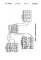
- FIG. 1a typical arrangement 14 for electrically connecting the ECM 10 with its network of actuators and sensors 12 is illustrated.
- This connection arrangementincludes an auto-side connector 16 having a series of auto-side plug-in terminals 18 respectively connected with associated sensors and actuators and a computer-side connector 20 disengageably connectable to the auto-side connector by means of corresponding, complementary computer-side plug-in terminals 22 connected to the appropriate circuitry within electronic control module 10.
- the auto-side terminals 18are shown as the male terminals and the computer-side terminals 22 are shown as female terminals.
- cooperating terminals 18, 22are designated T1, T2, T3 and so on.
- the oxygen sensormight be associated with terminal T1 in one vehicle and T5 in another.
- Vehicle makes and modelsmay include sensors and actuators that other vehicle makes and models do not have.
- a knock sensor used to sense engine knocks, which result in the ECM retarding spark timing,is found generally only in more expensive cars.
- the automotive service professionalmight use what is commonly referred to as a "breakout box", generally indicated by the reference numeral 24, for gaining access to all of the terminals T1-T10.
- the breakout boxhas its own adaptor 26 disposed between and connecting together auto-side connector 16 with computer-side connector 20 such that each terminal 18 remains connected to its associated terminal 22.
- adaptor 26is connected to the breakout box through a connecting harness 28 for electrically connecting the breakout box's own terminals 30 to corresponding terminals T1, T2, T3 and so on.
- the automotive service professionalcan easily gain access to any of the terminals T1-T10 by means of terminals 30.
- the breakout box 24is typically used by the automotive service professional to diagnose a problem associated with energization of a trouble light on the dashboard of the vehicle in question.
- Many vehicle makes and modelsinclude their own trouble code associated with each given trouble light.
- a trouble codeindicates some abnormal condition in a given circuit within the vehicle's electronic system.
- trouble code 42 on a GM vehiclemay indicate abnormal voltage readings from the oxygen sensor.
- a professionalmay connect the breakout box 24 and insert a voltmeter into the terminal associated with the oxygen sensor on that particular vehicle, say terminal T:, and verify the actual voltage in the circuit. It is worthwhile noting that whereas some trouble codes are very specific, others are quite general and in many cases the same code will be set for many different problems; further more, many problems will cause the setting of multiple trouble codes.
- the diagnostic system associated with the breakout box 24, as described above,is a passive system. That is, the automotive service professional uses the breakout box to access the connector terminals in order to observe the components associated with those terminals typically by connecting a volt meter and from those observations, he is hopefully able to diagnose the problem.
- a more particular object of the present inventionis to provide a diagnostic work station which utilizes its own external computer for continuously monitoring, preferably in real time, and analyzing electronic data entering and/or exiting the onboard computer of the vehicle being diagnosed including actual data associated with the vehicle's network of sensors and actuators
- Another particular object of the present inventionis to provide a state-of-the-art diagnostic work station that takes an interactive role, which means that it is not only capable of analyzing the electronic data entering and/or exiting the onboard computer, but it is also capable of controlling the operation of one or more specific actuators independent of the onboard computer and simulating the operation of one or more specific sensors, independent of the actual operation of these sensors, as contrasted with the previously described breakout box 24 which merely takes a passive role.
- Still another particular object of the present inventionis to provide a state-of-the-art diagnostic work station that is rapidly and easily adapted for use with different vehicle makes and models.
- the particular diagnostic work station, actually system, disclosed hereinis specifically designed for high technology automotive vehicles of the type described in conjunction with FIG. 1.
- a vehicleincluding (1) a network of sensors and actuators for independently sensing and actuating a number of different functions within the vehicle, (2) an onboard computer for monitoring the sensors and controlling operation of the actuators, and (3) cooperating auto-side and computer-side connectors having cooperating auto-side and computer-side plug-in terminals for electrically connecting the onboard computer with the sensors and actuators, again as described previously in conjunction with FIG. 1.
- the particular diagnostic work station disclosed hereinutilizes means including its own computer arrangement separate from the vehicle's onboard computer, for continuously monitoring and analyzing in real time electronic data entering and/or exiting the onboard computer, that is, the ECM, including actual data associated with the vehicle's network of sensors and actuators.
- the ECMelectronic data entering and/or exiting the onboard computer
- the monitorin association with the external computer arrangement, the outputs of a number of related sensors can be simultaneously observed visually while, at the same time, the operation of associated actuators are monitored.
- the diagnostic work station disclosed hereinincludes a series of components that cooperate with its external computer for allowing the work station to interact directly with the vehicle's network of sensors and actuators and its onboard computer. This is accomplished first by providing suitable means for selectively and temporarily disconnecting one or more specific sensors and/or one or more specific actuators from the vehicle's onboard computer. At the same time, the work station's external computer arrangement is temporarily connected with these latter sensors for simulating the action of each one independent of its actual operation and also connected to these latter actuators for controlling the operation of each of these actuators independent of the onboard computer.
- some of the other sensors and actuatorsthat is, those not disconnected from the vehicle's onboard computer, can be continuously monitored and analyzed by the external computer.
- the diagnostic work station disclosed hereinit is not necessary to move the vehicle to a location of high altitude or to subject the vehicle to high or low temperature conditions. Rather, all that is necessary is to disconnect the appropriate barometric and temperature sensors from the vehicle's onboard computer and, using the external computer arrangement, simulate the way the sensors would operate at high altitude and at high or low temperature conditions so that the onboard computer thinks these latter conditions exist. The onboard computer will then operate the rest of the vehicle functions as if that were the case and these latter functions can then be monitored and analyzed by the external computer under these simulated conditions.
- the diagnostic work station disclosed hereinmerely serves a passive role of continuously monitoring and analyzing the vehicle in question or actually interacts with the vehicle, as described briefly above, it is readily and rapidly adaptable for use with vehicles of different makes and models. This is because, although different vehicle makes and models include different sensors and/or actuators and different onboard computers, the work station's external computer is provided with a database for distinguishing between these differences.
- FIG. 1diagrammatically illustrates, partially in block-diagram, a diagnostic system designed in accordance with the prior art for use with high-technology automotive vehicles;
- FIG. 2is a diagrammatic illustration, partially in block-diagram, of a diagnostic work station for similar high-technology vehicles, but one which is designed in accordance with the present invention.
- FIG. 3is a diagrammatic illustration of a particular feature of the work station in FIG. 2.
- FIGS. 4 and 5are further diagrammatic illustrations depicting the way the system functions.
- FIG. 2illustrates a diagnostic work station 32 which is designed in accordance with the present invention to provide automotive service professionals with all the tools necessary to perform precision diagnostic testing on today's high technology vehicles.
- vehicle 34is diagrammatically illustrated in FIG. 2 and corresponds to the vehicle described heretofore in conjunction with FIG. 1.
- vehicle 34includes among other components, an entire auto-drive system 35 which itself includes an engine, transmission, brakes, and so on, as well as a network of sensors and actuators associated with these latter components.
- the sensors and actuatorsare indicated by the letters S and A with numerical subscripts distinguishing one from the other.
- Vehicle 34also includes an onboard computer, specifically the same electronic control module 10 and arrangement 14 for electrically connecting the ECM with the sensors and actuators as described in conjunction with FIG. 1.
- arrangement 14includes an auto-side connector 16 having its own auto-side plug-in terminals 18 and a computer-side connector 20 including its own computer-side plug-in terminals 22.
- terminals T1-T10For purposes of convenience, only ten terminals are illustrated, specifically terminals T1-T10. Most of these terminals connect associated sensors or actuators with appropriate circuitry at ECM 10.
- terminal T1connects ECM 10 with sensor S1
- terminal T2connects the ECM to sensor S2, and so on.
- the particular components M7 and G8 illustrated as part of the auto-drive system and connected to the ECM through terminals T7 and T8will be described hereinafter along with the function of terminal T9.
- diagnostic work station 32This work station includes its own external computer arrangement 36 which, as will be discussed in more detail below, is specifically designed for three primary purposes. First, it is designed to control the operation of one or more specific actuators independent of one another and independent of the onboard ECM 10. Second, it is designed to simulate the operation of one or more specific sensors, independent of one another and independent of their actual operation. Third, computer arrangement 36 is designed to continuously monitor and analyze in real time all of the electronic data entering and exiting ECM 10 including actual data associated with the network of sensors and actuators.
- work station 32also includes an arrangement 38 which also serves a number of purposes.
- arrangement 38serves to selectively and temporarily disconnect one or more specific sensors and/or actuators from ECM 10.
- arrangement 38serves to connect external computer arrangement 36 to those actuators that have been temporarily disconnected from ECM 10 so that the external computer arrangement can override the ECM and control those actuators.
- arrangement 38serves to connect the external computer arrangement 36 into the circuitry of ECM 10 associated with those sensors that have been temporarily disconnected in order to simulate the operation of those sensors.
- arrangement 38serves to connect external computer arrangement 36 to ECM 10 for monitoring the data entering and/or leaving the ECM, that is, the data passing between the ECM and various vehicle drive system components.
- actuator A6for example, actuator A6
- sensors S3 and S4it can also monitor the other actuators and sensors, that is, those actuators and sensors that remain connected to the ECM.
- the ECMBy modulating this signal in the same way as the actual sensor S4 would, the ECM can be made to believe that the engine itself is varying in temperature causing it to vary the ignition timing accordingly. As a result, the vehicle's advance-retard angle can be observed as a function of temperature without ever leaving the service garage.
- This systemis supposed to allow a certain amount of air to flow from the exhaust back into the intake manifold for controlling the temperature in the manifold by using the heat from the exhaust air.
- Thisis controlled by a certain actuator, for example, the exhaust recirculation valve in General Motors cars.
- this valvewill only open under certain conditions.
- One such conditionis when the vehicle is under load, as briefly mentioned earlier in the discussion of FIG. 1.
- the vehicle's ECMwill not itself open the exhaust recirculation valve since the vehicle itself is not under load.
- work station 32is especially appropriate.
- computer arrangement 36takes over control of certain actuators and simulates certain sensors to make ECM 10 think that the vehicle is under a load. At the same time, it continuously monitors the valve in question in order to see if it actually does open the proper way under this load.
- computer arrangement 36it is also possible to use computer arrangement 36 to directly control the EGR value, by disconnecting it from ECM 10, and driving it to open, simultaneously monitoring other vehicle conditions such as temperature and fuel modulation in order to discern whether the value is operating properly.
- work station 32may be used solely for monitoring and analyzing certain vehicle functions without any interactive role at all.
- An example of thismight be the vehicle's cruise control. Since the cruise control is not critical to the vehicle's operation, it may be desirable, from an economic standpoint, to provide the work station without means for interacting with the cruise control. In this case, the cruise control would be connected to computer arrangement 36 in a "monitor only" mode, in which case, the computer arrangement can still analyze operation of the cruise control and not directly affect its operation.
- work station 32In a most economical version of work station 32, it would be designed only to continuously monitor and analyze in real time electronic data entering and exiting the ECM without any interactive roles at all.
- the work stationserves as a highly sophisticated analytical tool far superior to the breakout box illustrated in FIG. 1, but would have less diagnostic capability than the interactive work station illustrated in FIG. 2.
- this latter arrangementincluding what may be referred to as a pod 40 which is comprised of a series of lines or channels C1, C2 and so on, include electronic switching circuits to be described below.
- This podis disengageably connectable to a vehicle adaptor 42 by means of their respective plug-in cable harnesses 44 and 46.
- Adaptor 42is comprised of its own auto-side connector 48 and its own computer-side connector 50, each of which includes its own plug-in terminals complementary to plug-in terminals 18 and 22. In this way the connectors 16 and 48 and the connectors 20 and 50 can be respectively connected together.
- the connectors 16 and 20may differ for different vehicle makes and models and, hence, different adapters must be used.
- the terminal T1 associated with the sensor S1 as shown in FIG. 2is connected to Channel C1.
- the terminal T1may be associated with different drive system component, for example, sensor S4, and might therefore be connected through the cooperating adaptor to Channel C 4 for example.
- each adapterhas its own unique way of connecting terminals T1, T2 and so on with channel lines C1, C2 and so on.
- pod 40is comprised of a series of electronic switching circuits which may be readily provided by those with ordinary skill in the art. However, for purposes of simplicity, these switching circuits are depicted in FIG. 2 as simple mechanical switches and will be referred to herein as either switches or switching circuits. It is important to note that there are three different sets of switching circuits which perform three different functions. There is a first set of switching circuits generally represented by the switches S1, S2, S3 and so on. A second set is indicated at S'1, S'2 and so on, while a third set is shown at S"5, S"6, S"8 and S"10. The function of each set will be described below.
- Switches S1, S2, S3 and so onfunction to selectively connect or disconnect corresponding auto-side terminals 18 to or from associated computer-side terminal 22.
- the switch S1 on channel line C1is shown in its closed condition, thereby connecting the T1 terminal 18 to the T1 terminal 22.
- Thiswill electrically connect the sensor S1 to its associated circuitry in ECM 10 through the plug-in terminals T1.
- switch S2 on channel line C2which maintains sensor S2 connected to ECM 10.
- sensors S3 and S4are shown in an opened condition, thereby disconnecting the T3 and T4 terminals 18 from the T3 and T4 terminals 22 which, in turn, disconnect sensors S3 and S4 from ECM 10.
- switches S6is open, switches S5 and S10 are closed, and there are no switches S associated with channel lines C7, C8 and C9.
- the C7 channel linewhich is a monitor only line as described above, may be connected to, for example, the connector terminals associated with the vehicle's cruise control. In this way, computer arrangement 36 can monitor and analyze the cruise control but it cannot interact with it.
- the C9 line in FIG. 2is actually provided to symbolically represent a series of lines for monitoring all of the other lines. This is more realistically depicted in FIG. 3, as will be seen.
- the C8 linewill be discussed hereinafter.
- the second series of switches, S'1, S'2 and so on,serve to connect corresponding computer-side terminals 22 to the sensor simulating circuitry 56 within computer arrangement 36 while the third series of switches S"5, S"6 and S"8 serve to connect the corresponding auto-side terminals 18 to the actuator driving circuit 56 within computer arrangement 36.
- switch S'1is shown opened and therefore assures that the circuitry within the ECM 10 and connected to the T1 computer-side terminal 22 is not driven by external computer arrangement 36.
- switching circuit S'3connects computer arrangement 36 to the circuitry in ECM 10 associated with sensor S3 through the T3 computer-side terminal 22.
- switching circuit S"6is closed and therefore connects actuator A6 with computer arrangement 36 through the T6 terminal 18.
- channel line C8the status of the other switching circuits should be self explanatory from FIG. 2 and the discussion immediately above.
- the switching circuits S'are associated with sensors and thus connect the computer arrangement 36 to ECM 10 while the switching circuits S" are associated with actuators and hence connect computer arrangement 36 to the actuators.
- line C 8it should be noted that it includes both an S' and an S" switching circuit. This is because the C 8 line serves to test the ground lines in the entire vehicle system. By closing the switch S'8, the ground lines in the ECM 10 can be resistance tested by injecting a known current into the line and measuring the resultant voltage. This is also true for the ground lines of the vehicle drive system side by closing the switch S"8. While only one such line C8 is shown, there are usually a number of such lines.
- this arrangementincludes its own CPU 52 which can be, for example, part of a readily providable personal computer including an associated monitor 54 and keyboard 55.
- the arrangementalso provides a suitable and readily providable interface between the computer including the necessary digital/analog converters one of which is generally indicated at 56 and analog/digital converters generally indicated at 58.
- the digital/analog converters 56allow CPU 52 to drive (actually control the operation of) particular vehicle actuators through switching circuits S" and simulate particular sensors feeding into circuitry within the ECM 10 through cooperating switching circuits S'.
- the analog/digital convertersallow the external CPU 52 to "listen to", that is, monitor data entering and leaving ECM 10.
- one or more A/D converterscan be used for listening to all the terminal lines utilizing a suitable and readily providable sweep mechanism which is operated in a time slicing mode.
- some of the D/A converters associated with actuatorsare actually driver circuits including on-off switches.
- channels C1-C10 in pod 40connect to A/D circuitry 58 through a conventional and readily providable multiplexer 59 forming part of the sweep mechanism just mentioned so that individual terminal lines and specific groups of terminal lines can be scanned by the CPU.
- CPU 52may be part of any suitable and readily providable computer, for example a standard personal computer.
- the software used to run the computerrepresented generally by the diagrammatically depicted look up table 59 or menu, is also readily providable by those with ordinary skill in the art in view of the teachings herein.
- the softwaremust be designed to control the various actuators in the intended manner and simulate the various sensors. It also must have the ability to analyze the various data presented to the external computer.
- a particular feature of work station 32resides in a specific software database maintained within CPU 52.
- different vehicle makes and/or models compatible with work station 32may include different sensors or actuators, different onboard computers and/or a different arrangement of auto-side and computer-side terminals.
- external CPU 52includes a database for distinguishing between any of these differences in different vehicle makes and models.
- the automotive service professionalcan easily enter the appropriate vehicle identification into CPU 52 using keyboard 55 and provide the appropriate adaptor 32 in order to make the work station compatible with the particular vehicle in question.
- the databasealso includes performance information pertaining to specific sensors and actuators for particular vehicle makes and models.
- the CPU and its softwareinclude suitable and readily providable means for storing electronic data presented to it into memory, a database having exemplary data associated with the networks of sensors and actuators, and means for comparing the actual data stored in memory with the exemplary data.
- the CPU and its softwarealso include suitable and readily providable means for carrying out different diagnostic tests by operating certain specific actuators and simulating certain specific sensors in a predetermined way.
- Software menu 60is shown specifically including an "AUTO SELECT" item which represents a data base for distinguishing between vehicle makes and models.
- the T1-T10 itemsrepresent data associated with the sensors, actuators and other components connected with connector terminals T1-T10. As stated above, this data varies with the particular vehicle selected and would include for certain components the desired performance criteria to be used as a reference against actual performance data.
- the items labeled "Test No. 1", “Test No. 2" and so onrefer to a data base for carrying out different predetermined diagnostic tests.
- the menu 60 illustrated in FIG. 2is by no means complete, nor is it intended to be complete. It is provided rather as an example of the necessary software required to operate CPU 52 in the desired manner, which software is readily providable, as indicated above. A more detailed discussion of the way in which the overall work station operates from a software standpoint will follow.
- the terminal lines associated with terminals T1 and T2are shown as monitoring lines and, hence, include no switching circuits at all.
- the terminal lines associated with terminals T3, T4 and T5do include switching circuits.
- a single switching circuitis used to combine the function of the previously described switches S and S' or S".
- a single switching circuit S"3is used to connect the auto-side and ECM side terminals T3 to one another and alternatively to connect the ECM side terminal T3 to D/A circuitry within computer arrangement 36. This is also the case for switching circuit S"4.
- the terminal line T5includes a switching circuit Sw5 which in one position connects together the ECM side and auto-side terminals T5 and in the opposite position connects computer arrangement 36, actually its driver circuit 56, to the auto side terminal T5 for connection with the associated actuator A5.
- a switching circuit Sw5which in one position connects together the ECM side and auto-side terminals T5 and in the opposite position connects computer arrangement 36, actually its driver circuit 56, to the auto side terminal T5 for connection with the associated actuator A5.
- driver circuitsincluding on/off switches rather than through D/A converters.
- any given actuatoris always driven by the external computer in a way which is consistent with the actuator's electrical properties, i.e., voltage, current, impedance, etc.
- a solenoidrequires different drive parameters than a stepper monitor. Note also that not only the monitoring lines T1 and T2 in FIG.
- A/D convertersare shown including A/D converters but all of the other lines, that is, those including switching circuits also include A/D converters which serve to monitor or listen to those lines, regardless of the position of any given switching circuit. In this latter regard, in actual practice, it may be desirable to include a single A/D converter for listening purposes along with a sweep mechanism operated in a time slice mode.
- the data base (DB)is composed of various tables as shown in FIG. 4, as follows:
- Component TableFor every component used with any vehicle, there is an entry in this table. Every entry contains the component identification (ID), type (sensor, thermistor, solenoid, etc.) and electrical parameters (min-max volts, resistance, inductance, translation tables to physical units, etc.).
- IDcomponent identification
- typesensor, thermistor, solenoid, etc.
- electrical parametersmin-max volts, resistance, inductance, translation tables to physical units, etc.
- Channel TableFor every channel Cl, C2 and so on in the pod there is an entry in this table. Every entry contains the channel mux-address, the switch address, the D/A address, and other electrical parameters (i.e. gain, impedence, drive capabilities, etc.).
- Every entryis itself a table with an entry for every terminal on the particular ECM. Every terminal entry contains the terminal name (e.g., T1, T2), the component connected to this terminal, and the channel C1, C2, and so on, through which this terminal is routed in pod 40.
- T1, T2the terminal name
- VINvehicle ID number
- general engine informationi.e., number of cylinders, ignition type, injection type, etc.
- Different componentsmay connect to same terminal on different connectors.
- Some channelsmay connect to different components on different connectors.
- the first examplewill be what is called a sweep test, invoked by say item Test No. 1 in menu 60 of FIG. 2.
- the sweep testis a software function that examines all terminals of a given vehicle sequentially, monitoring them under known conditions for abnormal behavior.
- the second example to be discussedis a functional bypass test, invoked say by item Test No. 5 of menu 60, FIG. 2.
- a functional testwill look at a group of terminals simultaneously, examining a particular correlation in their operation.
- Sweep testsare divided into functional groups: key off, key on-engine off, cranking and engine running tests.
- the vehicle ECMUnder constant running conditions (RPM and load) the vehicle ECM will constantly monitor the oxygen sensor output which may be high, indicating high oxygen contents in the exhaust manifold, or low, indicating low oxygen.
- the ECMresponds by modulating the fuel injectors to counter the oxygen readings.
- oxygenwhen oxygen is high, the ECM will widen the injector pulse width, causing more fuel to be delivered into the combustion chamber, eventually reducing the oxygen contents in the exhaust manifold, and vice versa when oxygen is low.
- This schemeis called a negative feedback loop, where injector pulse width is the controlled variable and oxygen is the error signal.
- Test DescriptionWhile the engine is running, the system 32 will inject a simulated oxygen signal into the ECM.
- the signalis a square wave, with min-max voltage range based on DB values for a given oxygen sensor. While injecting this signal, the system will simultaneously monitor the Injector driver line, computing in real time the variation in injector pulse width, and also the output of the real oxygen sensor.
- a software functionis provided within the system to execute the above test.
- the connector table for the vehicle(FIG. 4) is scanned, searching for the terminals corresponding to the oxygen signal, the injector drivers (one or more) and the tach signal (RPM).
- the oxygen channel switchis configured for bypass into the ECM.
- the appropriate D/Ais configured to generate a square wave with min-max voltage equal to nominal values for oxygen from the DB.
- the injector driver, the oxygen sensor and the tach signalare configured for "Read" (to listen) by properly selecting their respective channels in the A/D mux.
- the useris instructed to rev the engine to 2000 RPM, and the test begins:
- the systemmonitors the tach signal, waiting for 2000 RPM. At that point, the D/A is enabled which causes the simulated signal to be generated.
- the programthen monitors simultaneously the simulated value, the real oxygen value and the injector driver.
- the injector signalis converted in real time to a pulse-width value, and is plotted against time together with the other values. This goes on for approximately 15 seconds, at which time bypass is disabled and monitoring stops.
- the final stageis a mathematical computation done on the data recorded in memory. The correlation of simulated oxygen and injector pulse width is computed, and the skew between simulated oxygen and real oxygen is measured. Both values are compared against good known results.
- the present inventionis not limited to the particular computer arrangement 36 or the particular connector arrangement 38 illustrated in FIGS. 2 and 3. Rather, based on the teachings herein, one with ordinary skill in the art can readily modify either of these arrangements so long as they fulfill the functions herein. Moreover, based on the teachings herein, and with suitable and readily providable knowledge about particular automotive vehicles, one with ordinary skill in the software art can readily design the software used to operate computer 52.
- the present inventiondoes not relate to the software per se but rather to the way in which the overall diagnostic station is able to continuously monitor and analyze vehicle 34 and more particularly to the way it is able to take an interactive role in the diagnostic process. In an actual working embodiment, an IBM PC AT or compatible system has been provided. Tables 1-3 forming the Appendix I attached hereto list examples of actual engines, specific functions and tests by the actual embodiment. The present invention contemplates but is not limited to these particular engines, functions and tests. ##SPC1##
Landscapes
- Physics & Mathematics (AREA)
- General Physics & Mathematics (AREA)
- Engineering & Computer Science (AREA)
- Combustion & Propulsion (AREA)
- Microelectronics & Electronic Packaging (AREA)
- Chemical & Material Sciences (AREA)
- Computer Hardware Design (AREA)
- Testing And Monitoring For Control Systems (AREA)
- Control Of Electric Motors In General (AREA)
- Testing Or Calibration Of Command Recording Devices (AREA)
- Automobile Manufacture Line, Endless Track Vehicle, Trailer (AREA)
- Electric Propulsion And Braking For Vehicles (AREA)
- Testing Of Engines (AREA)
- Vehicle Cleaning, Maintenance, Repair, Refitting, And Outriggers (AREA)
Abstract
Description
Claims (32)
Priority Applications (10)
| Application Number | Priority Date | Filing Date | Title |
|---|---|---|---|
| US07647774US5214582C1 (en) | 1991-01-30 | 1991-01-30 | Interactive diagnostic system for an automobile vehicle and method |
| JP04506273AJP3081243B2 (en) | 1991-01-30 | 1992-01-29 | Automotive interactive diagnostic device and method |
| DE69232029TDE69232029T2 (en) | 1991-01-30 | 1992-01-29 | INTERACTIVE DIAGNOSTIC SYSTEM AND METHOD FOR A MOTOR VEHICLE |
| DK92906083TDK0575399T3 (en) | 1991-01-30 | 1992-01-29 | Interactive diagnostic system for a motor vehicle and method |
| PCT/US1992/000721WO1992014216A1 (en) | 1991-01-30 | 1992-01-29 | Interactive diagnostic system for an automotive vehicle, and method |
| AT92906083TATE204990T1 (en) | 1991-01-30 | 1992-01-29 | INTERACTIVE DIAGNOSTICS SYSTEM AND METHOD FOR A MOTOR VEHICLE |
| EP92906083AEP0575399B1 (en) | 1991-01-30 | 1992-01-29 | Interactive diagnostic system for an automotive vehicle, and method |
| EP01200566AEP1116955A3 (en) | 1991-01-30 | 1992-01-29 | Interactive diagnostic system |
| CA002101336ACA2101336C (en) | 1991-01-30 | 1992-01-29 | Interactive diagnostic system for an automotive vehicle, and method |
| ES92906083TES2163397T3 (en) | 1991-01-30 | 1992-01-29 | PROCEDURE AND SYSTEM OF INTERACTIVE DIAGNOSIS FOR A CAR. |
Applications Claiming Priority (1)
| Application Number | Priority Date | Filing Date | Title |
|---|---|---|---|
| US07647774US5214582C1 (en) | 1991-01-30 | 1991-01-30 | Interactive diagnostic system for an automobile vehicle and method |
Publications (2)
| Publication Number | Publication Date |
|---|---|
| US5214582Atrue US5214582A (en) | 1993-05-25 |
| US5214582C1 US5214582C1 (en) | 2001-06-26 |
Family
ID=24598218
Family Applications (1)
| Application Number | Title | Priority Date | Filing Date |
|---|---|---|---|
| US07647774Expired - LifetimeUS5214582C1 (en) | 1991-01-30 | 1991-01-30 | Interactive diagnostic system for an automobile vehicle and method |
Country Status (9)
| Country | Link |
|---|---|
| US (1) | US5214582C1 (en) |
| EP (2) | EP0575399B1 (en) |
| JP (1) | JP3081243B2 (en) |
| AT (1) | ATE204990T1 (en) |
| CA (1) | CA2101336C (en) |
| DE (1) | DE69232029T2 (en) |
| DK (1) | DK0575399T3 (en) |
| ES (1) | ES2163397T3 (en) |
| WO (1) | WO1992014216A1 (en) |
Cited By (230)
| Publication number | Priority date | Publication date | Assignee | Title |
|---|---|---|---|---|
| US5327344A (en)* | 1992-09-16 | 1994-07-05 | Caterpillar Inc. | Method and apparatus for reconfiguring a computerized monitoring system |
| US5327343A (en)* | 1990-09-01 | 1994-07-05 | Daimler-Benz Ag | Universally and bidirectionally operable device for signal path control in a motor vehicle diagnostic system |
| US5345383A (en)* | 1992-09-16 | 1994-09-06 | Caterpillar Inc. | Method and apparatus for selectively monitoring input |
| US5347260A (en)* | 1992-09-16 | 1994-09-13 | Caterpillar Inc. | Method and apparatus for receiving data |
| US5361059A (en)* | 1992-09-16 | 1994-11-01 | Caterpillar Inc. | Method and apparatus for modifying the functionality of a gauge |
| US5369392A (en)* | 1992-09-16 | 1994-11-29 | Caterpillar Inc. | Method and apparatus for indicating faults in switch-type inputs |
| US5371487A (en)* | 1992-09-16 | 1994-12-06 | Caterpillar Inc. | Method and apparatus for indicating a changed condition |
| US5408412A (en)* | 1992-04-09 | 1995-04-18 | United Technologies Corporation | Engine fault diagnostic system |
| US5442170A (en)* | 1994-04-15 | 1995-08-15 | Balco, Incorporated | Programmable cable adaptor for connecting different automobile computers to diagnostic equipment |
| US5453939A (en)* | 1992-09-16 | 1995-09-26 | Caterpillar Inc. | Computerized diagnostic and monitoring system |
| US5459660A (en)* | 1993-12-22 | 1995-10-17 | Chrysler Corporation | Circuit and method for interfacing with vehicle computer |
| US5463567A (en)* | 1993-10-15 | 1995-10-31 | Caterpillar Inc. | Apparatus and method for providing historical data regarding machine operating parameters |
| US5507326A (en)* | 1994-08-05 | 1996-04-16 | Scully Signal Company | Fluid overfill protection and product identification system |
| US5530360A (en)* | 1994-12-09 | 1996-06-25 | Chrysler Corporation | Apparatus and method for diagnosing faults in a vehicle electrical system |
| US5532927A (en)* | 1990-07-27 | 1996-07-02 | V. L. Churchill, Ltd. | Automotive diagnostic tool |
| US5534856A (en)* | 1993-11-18 | 1996-07-09 | Scully Signal Company | Vehicle identification and verification system |
| US5535620A (en)* | 1993-04-05 | 1996-07-16 | Applied Computer Engineering, Inc. | Engine management system |
| US5550762A (en)* | 1993-12-20 | 1996-08-27 | Doll; John A. | Diagnostic system for electronic automotive system |
| US5574645A (en)* | 1995-02-28 | 1996-11-12 | Snap-On Technologies, Inc. | Manifold absolute pressure sensor emulator |
| US5631831A (en)* | 1993-02-26 | 1997-05-20 | Spx Corporation | Diagnosis method for vehicle systems |
| US5644491A (en)* | 1994-01-31 | 1997-07-01 | Sendec Corporation | Self contained multi-function engine monitor and timer for providing engine running time, job time, service time and tachometer functions |
| US5646865A (en)* | 1994-10-27 | 1997-07-08 | General Motors Corporation | Automotive diagnostic communications |
| US5659680A (en)* | 1995-06-30 | 1997-08-19 | Micro Processor Systems, Inc. | PC compatible modular based diagnostic system |
| US5671141A (en)* | 1993-04-05 | 1997-09-23 | Ford Global Technologies, Inc. | Computer program architecture for onboard vehicle diagnostic system |
| US5683261A (en)* | 1994-05-19 | 1997-11-04 | Spx Corporation | Removable coupling module for mechanically multiplexing conductors |
| US5686840A (en)* | 1996-05-08 | 1997-11-11 | Automotive Controls Corporation | Method and apparatus for throttle position sensor testing |
| US5700090A (en)* | 1996-01-03 | 1997-12-23 | Rosemount Inc. | Temperature sensor transmitter with sensor sheath lead |
| US5713007A (en)* | 1993-12-14 | 1998-01-27 | Aerospatiale Societe Nationale Industrielle | Process and device for detecting operating inconsistencies in a system with multiple phases of operation |
| US5746511A (en)* | 1996-01-03 | 1998-05-05 | Rosemount Inc. | Temperature transmitter with on-line calibration using johnson noise |
| US5771474A (en)* | 1994-01-04 | 1998-06-23 | Robertbosch Gmbh | Method for testing electronic control devices |
| US5793649A (en)* | 1993-03-17 | 1998-08-11 | Kioritz Corporation | Apparatus for measuring the operation of vehicular engines |
| US5798647A (en)* | 1996-05-06 | 1998-08-25 | Chrysler Corporation | Diagnostic test controller apparatus |
| US5828567A (en)* | 1996-11-07 | 1998-10-27 | Rosemount Inc. | Diagnostics for resistance based transmitter |
| WO1999010751A1 (en)* | 1997-08-27 | 1999-03-04 | Factor 1 Limited | Fuel injection diagnostic control device |
| WO1999036839A1 (en)* | 1998-01-16 | 1999-07-22 | WILLIAMS, Norman, George | User configurable bimodular engine management computer |
| US5956663A (en)* | 1996-11-07 | 1999-09-21 | Rosemount, Inc. | Signal processing technique which separates signal components in a sensor for sensor diagnostics |
| US6003808A (en)* | 1997-07-11 | 1999-12-21 | Pratt & Whitney Canada Inc. | Maintenance and warranty control system for aircraft |
| US6014598A (en)* | 1996-06-28 | 2000-01-11 | Arcelik A.S. | Model-based fault detection system for electric motors |
| US6017143A (en)* | 1996-03-28 | 2000-01-25 | Rosemount Inc. | Device in a process system for detecting events |
| WO2000012993A1 (en)* | 1998-08-27 | 2000-03-09 | Automotive Electronics, Inc. | Electronic control assembly testing system |
| US6047220A (en)* | 1996-12-31 | 2000-04-04 | Rosemount Inc. | Device in a process system for validating a control signal from a field device |
| US6073088A (en)* | 1997-02-14 | 2000-06-06 | Schlumberger Technologies, Inc. | EMS testing system |
| WO2000034838A1 (en)* | 1998-12-04 | 2000-06-15 | Edge Diagnostic Systems | Modular vehicle diagnostic system |
| US6097998A (en)* | 1998-09-11 | 2000-08-01 | Alliedsignal Truck Brake Systems Co. | Method and apparatus for graphically monitoring and controlling a vehicle anti-lock braking system |
| EP0819928A4 (en)* | 1996-02-05 | 2000-08-02 | Honda Motor Co Ltd | Car diagnosis method and apparatus |
| US6134488A (en)* | 1997-03-10 | 2000-10-17 | Honda Giken Kogyo Kabushiki Kaisha | Method and device for diagnosis for vehicle |
| US6151547A (en)* | 1999-02-24 | 2000-11-21 | Engelhard Corporation | Air/fuel ratio manipulation code for optimizing dynamic emissions |
| US6157877A (en)* | 1995-09-05 | 2000-12-05 | Sun Electric U.K. Limited | Apparatus and method for testing automotive electronic control units and batteries and related equipment |
| US6169943B1 (en)* | 1999-07-14 | 2001-01-02 | Eaton Corporation | Motor vehicle diagnostic system using hand-held remote control |
| US6297646B1 (en)* | 1997-06-25 | 2001-10-02 | Snap-On Tools Company | Electrical tester for small motor vehicles |
| US6298454B1 (en) | 1999-02-22 | 2001-10-02 | Fisher-Rosemount Systems, Inc. | Diagnostics in a process control system |
| US6311162B1 (en) | 1998-07-25 | 2001-10-30 | Ernst F. Reichwein | Interactive symptomatic recording system and methods |
| US6314375B1 (en)* | 1997-03-10 | 2001-11-06 | Honda Giken Kogyo Kabushiki Kaisha | Method and device for diagnosis for vehicle |
| US6321142B1 (en) | 2000-05-16 | 2001-11-20 | Cummins Engine Company, Inc. | System for programming a vehicle control computer with selectable features and/or trim values |
| US6330587B1 (en) | 1998-12-21 | 2001-12-11 | Ford Global Technologies, Inc. | Real-time multiprocessing computer infrastructure for automated testing |
| US6345257B1 (en)* | 1998-12-14 | 2002-02-05 | National Railroad Passenger Corporation | Computer based interactive defect reporting system for the paperless reporting of problems in a vehicle forming part of a fleet |
| US20020022894A1 (en)* | 2000-05-23 | 2002-02-21 | Evren Eryurek | Enhanced fieldbus device alerts in a process control system |
| US6356191B1 (en) | 1999-06-17 | 2002-03-12 | Rosemount Inc. | Error compensation for a process fluid temperature transmitter |
| US6363302B1 (en)* | 1999-05-07 | 2002-03-26 | Robert Bosch Gmbh | Method and apparatus for operating a control unit for controlling operational sequences in a vehicle |
| US6370448B1 (en) | 1997-10-13 | 2002-04-09 | Rosemount Inc. | Communication technique for field devices in industrial processes |
| WO2002037399A1 (en)* | 2000-11-03 | 2002-05-10 | Detroit Diesel Corporation | Sensor simulator for calibration and service of internal combustion engines |
| US20020073000A1 (en)* | 2000-05-05 | 2002-06-13 | Mike Sage | System and method for implementing a wireless network in a service center for generating a repair order |
| US20020077711A1 (en)* | 1999-02-22 | 2002-06-20 | Nixon Mark J. | Fusion of process performance monitoring with process equipment monitoring and control |
| US6429773B1 (en) | 2000-10-31 | 2002-08-06 | Hewlett-Packard Company | System for remotely communicating with a vehicle |
| US6434504B1 (en) | 1996-11-07 | 2002-08-13 | Rosemount Inc. | Resistance based process control device diagnostics |
| US6449574B1 (en) | 1996-11-07 | 2002-09-10 | Micro Motion, Inc. | Resistance based process control device diagnostics |
| US6473710B1 (en) | 1999-07-01 | 2002-10-29 | Rosemount Inc. | Low power two-wire self validating temperature transmitter |
| US6477453B2 (en)* | 2000-12-28 | 2002-11-05 | Denso Corporation | Controller for vehicle with self-diagnostic function and recording medium |
| US6505517B1 (en) | 1999-07-23 | 2003-01-14 | Rosemount Inc. | High accuracy signal processing for magnetic flowmeter |
| US20030028268A1 (en)* | 2001-03-01 | 2003-02-06 | Evren Eryurek | Data sharing in a process plant |
| US6519546B1 (en) | 1996-11-07 | 2003-02-11 | Rosemount Inc. | Auto correcting temperature transmitter with resistance based sensor |
| KR100373007B1 (en)* | 2000-07-13 | 2003-02-25 | 현대자동차주식회사 | Windows monitoring tool of control unit for vehicle |
| US6539267B1 (en) | 1996-03-28 | 2003-03-25 | Rosemount Inc. | Device in a process system for determining statistical parameter |
| US6542799B2 (en)* | 1999-11-30 | 2003-04-01 | Mitsubishi Jidosha Kogyo Kabushiki Kaisha | Vehicle trouble diagnosis method, vehicle trouble diagnosis apparatus and computer-readable record medium recording trouble diagnosis program |
| US6556145B1 (en) | 1999-09-24 | 2003-04-29 | Rosemount Inc. | Two-wire fluid temperature transmitter with thermocouple diagnostics |
| US20030093522A1 (en)* | 1995-06-05 | 2003-05-15 | Tetsuro Motoyama | Method and system for diagnosis or control of machines |
| US6571191B1 (en) | 1998-10-27 | 2003-05-27 | Cummins, Inc. | Method and system for recalibration of an electronic control module |
| US20030125851A1 (en)* | 2001-12-31 | 2003-07-03 | Keith Andreasen | Automotive code reader |
| US6601005B1 (en) | 1996-11-07 | 2003-07-29 | Rosemount Inc. | Process device diagnostics using process variable sensor signal |
| US6611775B1 (en) | 1998-12-10 | 2003-08-26 | Rosemount Inc. | Electrode leakage diagnostics in a magnetic flow meter |
| US6615149B1 (en) | 1998-12-10 | 2003-09-02 | Rosemount Inc. | Spectral diagnostics in a magnetic flow meter |
| US20030171905A1 (en)* | 2001-02-13 | 2003-09-11 | Horst Wagner | Method and device for emulating control and/or regulating functions of a control or regulating device |
| US6629059B2 (en) | 2001-05-14 | 2003-09-30 | Fisher-Rosemount Systems, Inc. | Hand held diagnostic and communication device with automatic bus detection |
| US6633782B1 (en) | 1999-02-22 | 2003-10-14 | Fisher-Rosemount Systems, Inc. | Diagnostic expert in a process control system |
| US20030200015A1 (en)* | 2000-02-09 | 2003-10-23 | Oshkosh Truck Corporation | Equipment service vehicle having on-board diagnostic system |
| US6654697B1 (en) | 1996-03-28 | 2003-11-25 | Rosemount Inc. | Flow measurement with diagnostics |
| US6701274B1 (en) | 1999-08-27 | 2004-03-02 | Rosemount Inc. | Prediction of error magnitude in a pressure transmitter |
| US20040044605A1 (en)* | 2002-08-29 | 2004-03-04 | International Business Machines Corporation | Anticipatory mobile system service brokering and resource planning from multiple providers |
| US6735484B1 (en) | 2000-09-20 | 2004-05-11 | Fargo Electronics, Inc. | Printer with a process diagnostics system for detecting events |
| US20040093243A1 (en)* | 2002-11-07 | 2004-05-13 | International Business Machines Corporation | Supplemental diagnostic and services resource planning for mobile systems |
| US20040093299A1 (en)* | 2002-11-07 | 2004-05-13 | International Business Machines Corporation | System and method for coalescing information for presentation to a vehicle operator |
| US20040093289A1 (en)* | 2002-11-07 | 2004-05-13 | International Business Machines Corporation | Location based services anonymous session tracking and anonymous information aggregation |
| US6754601B1 (en) | 1996-11-07 | 2004-06-22 | Rosemount Inc. | Diagnostics for resistive elements of process devices |
| WO2004063949A2 (en) | 2003-01-09 | 2004-07-29 | Siemens Energy & Automation, Inc. | Method and system for computer-assisted testing of a machine system |
| US6772036B2 (en) | 2001-08-30 | 2004-08-03 | Fisher-Rosemount Systems, Inc. | Control system using process model |
| WO2004104969A1 (en)* | 2003-05-26 | 2004-12-02 | Teekay Norway As | A method and a simulator device for training a pilot of a vessel |
| US20040249583A1 (en)* | 1996-03-28 | 2004-12-09 | Evren Eryurek | Pressure transmitter with diagnostics |
| US6831375B1 (en) | 2000-09-06 | 2004-12-14 | Paccar Inc. | Diagnostics, protection, and isolation system for electronic devices on a vehicle data communication bus |
| US20050015380A1 (en)* | 2001-08-17 | 2005-01-20 | Rainer Burkhardt | Communication method and communication module |
| WO2005034047A1 (en)* | 2003-10-03 | 2005-04-14 | Snap-On Technologies, Inc. | System and method for diagnosing an automotive vehicle |
| US20050096806A1 (en)* | 2003-11-03 | 2005-05-05 | Diem Earl D. | Non-intrusive diagnostic tool for sensing oxygen sensor operation |
| US6907383B2 (en) | 1996-03-28 | 2005-06-14 | Rosemount Inc. | Flow diagnostic system |
| US6920799B1 (en) | 2004-04-15 | 2005-07-26 | Rosemount Inc. | Magnetic flow meter with reference electrode |
| US20050171735A1 (en)* | 2004-01-16 | 2005-08-04 | David Huang | Handheld diagnostic device and method for displaying bitmapped graphic characters utilizing a condensed bitmap character library |
| US20050182534A1 (en)* | 2003-12-31 | 2005-08-18 | Ian Legate | Telematics-based vehicle data acquisition architecture |
| US6941203B2 (en)* | 2001-09-21 | 2005-09-06 | Innova Electronics Corporation | Method and system for computer network implemented vehicle diagnostics |
| US6970003B2 (en) | 2001-03-05 | 2005-11-29 | Rosemount Inc. | Electronics board life prediction of microprocessor-based transmitters |
| WO2005121915A1 (en)* | 2004-06-08 | 2005-12-22 | Marine Cybernetics As | Method for testing of a combined dynamic positioning and power management system |
| US20060030981A1 (en)* | 2004-07-22 | 2006-02-09 | Snap-On Incorporated | Automated analysis of vehicle diagnostic data stream to identify anomaly |
| US20060027650A1 (en)* | 2004-07-22 | 2006-02-09 | Keith Andreasen | Scan tool user interface |
| US7010459B2 (en) | 1999-06-25 | 2006-03-07 | Rosemount Inc. | Process device diagnostics using process variable sensor signal |
| EP1530168A3 (en)* | 2003-11-07 | 2006-03-08 | Fulvio Ravo | Apparatus for remote diagnosis of motor vehicles |
| US20060052921A1 (en)* | 2002-11-07 | 2006-03-09 | Bodin William K | On-demand system for supplemental diagnostic and service resource planning for mobile systems |
| US20060058929A1 (en)* | 2004-02-16 | 2006-03-16 | Marine Cybernetics As | Method and system for testing a control system of a marine vessel |
| US7018800B2 (en) | 2003-08-07 | 2006-03-28 | Rosemount Inc. | Process device with quiescent current diagnostics |
| US7046180B2 (en) | 2004-04-21 | 2006-05-16 | Rosemount Inc. | Analog-to-digital converter with range error detection |
| US20060106966A1 (en)* | 2004-09-02 | 2006-05-18 | Eugen Joos | Data bus interface for a control unit, and control unit having a data bus interface |
| US20060111855A1 (en)* | 2004-11-19 | 2006-05-25 | Marine Cybernetics As | Test method and system for dynamic positioning systems |
| US20060116796A1 (en)* | 2002-12-30 | 2006-06-01 | Marine Cybernetics As | System and method for testing a control system of a marine vessel |
| US20060122747A1 (en)* | 2004-12-03 | 2006-06-08 | Brown Jack E Jr | Method for detection of low leak rates in a tire |
| KR100602801B1 (en)* | 1996-08-22 | 2006-07-20 | 로베르트 보쉬 게엠베하 | Diagnostic method for electric devices |
| US7085610B2 (en) | 1996-03-28 | 2006-08-01 | Fisher-Rosemount Systems, Inc. | Root cause diagnostics |
| US7085680B2 (en) | 2004-01-16 | 2006-08-01 | Innova Electronics Corporation | Vehicle diagnostic tool |
| US20060229777A1 (en)* | 2005-04-12 | 2006-10-12 | Hudson Michael D | System and methods of performing real-time on-board automotive telemetry analysis and reporting |
| US20060243788A1 (en)* | 2005-04-04 | 2006-11-02 | David Waco | Method and apparatus for wireless PC tablet presentation process |
| US20060271255A1 (en)* | 2004-12-30 | 2006-11-30 | Teradyne, Inc. | System and method for vehicle diagnostics and prognostics |
| US20060293811A1 (en)* | 2005-06-24 | 2006-12-28 | Keith Andreasen | Automotive data logger |
| US20070005201A1 (en)* | 2005-06-30 | 2007-01-04 | Chenn Ieon C | Cellphone based vehicle diagnostic system |
| US20070100478A1 (en)* | 2005-10-31 | 2007-05-03 | Marine Cybernetics As | Method and system for testing a control system for a marine petroleum process plant |
| US7221988B2 (en) | 2001-03-01 | 2007-05-22 | Rosemount, Inc. | Creation and display of indices within a process plant |
| WO2007096210A1 (en)* | 2006-02-22 | 2007-08-30 | Robert Bosch Gmbh | Method and circuit arrangement for simulating fault states in a control device |
| US7272531B2 (en) | 2005-09-20 | 2007-09-18 | Fisher-Rosemount Systems, Inc. | Aggregation of asset use indices within a process plant |
| US20070225880A1 (en)* | 2006-03-27 | 2007-09-27 | Eddie Sirhan | Test interface for diagnosing communication faults in automobiles |
| US7290450B2 (en) | 2003-07-18 | 2007-11-06 | Rosemount Inc. | Process diagnostics |
| US20070299592A1 (en)* | 2004-08-13 | 2007-12-27 | Romer Richard A | Drivetrain protection and management system |
| US7321846B1 (en) | 2006-10-05 | 2008-01-22 | Rosemount Inc. | Two-wire process control loop diagnostics |
| US20080053189A1 (en)* | 2006-08-31 | 2008-03-06 | Christopher Bell | Active wheel speed sensor tester |
| EP1906154A1 (en)* | 2006-09-29 | 2008-04-02 | Fanuc Ltd | Circuit for emulating encoder data |
| US20080125884A1 (en)* | 2006-09-26 | 2008-05-29 | Schumacher Mark S | Automatic field device service adviser |
| US20080177438A1 (en)* | 2005-06-24 | 2008-07-24 | Innova Electronics Corporation | Vehicle diagnostic system |
| US20080215291A1 (en)* | 2000-03-09 | 2008-09-04 | Wegerich Stephan W | Complex signal decomposition and modeling |
| US20080288315A1 (en)* | 2002-11-07 | 2008-11-20 | William Kress Bodin | Location Based Services Revenue Sharing and Cost Offsetting |
| US7467051B2 (en) | 2005-12-07 | 2008-12-16 | Marine Cybernetics As | Method and a system for testing of a power management system of a marine vessel |
| US20090006476A1 (en)* | 2007-06-28 | 2009-01-01 | Innova Electronics Corporation | Automotive diagnostic and remedial process |
| US7523667B2 (en) | 2003-12-23 | 2009-04-28 | Rosemount Inc. | Diagnostics of impulse piping in an industrial process |
| US20090118893A1 (en)* | 2007-11-05 | 2009-05-07 | Xiuyu Che | Method of integrated detection for automobile instruments |
| US7557702B2 (en) | 1999-02-22 | 2009-07-07 | Evren Eryurek | Integrated alert generation in a process plant |
| US7577581B1 (en) | 2000-10-31 | 2009-08-18 | Hewlett-Packard Development Company, L.P. | Method for targeting promotions to individual associated with a vehicle |
| US7590511B2 (en) | 2007-09-25 | 2009-09-15 | Rosemount Inc. | Field device for digital process control loop diagnostics |
| US7603293B2 (en) | 2005-06-24 | 2009-10-13 | Innova Electronics Corporation | Method of providing diagnostic information in connection with the sale of pre-owned vehicles |
| US20090276115A1 (en)* | 2005-06-30 | 2009-11-05 | Chen Ieon C | Handheld Automotive Diagnostic Tool with VIN Decoder and Communication System |
| US7623932B2 (en) | 1996-03-28 | 2009-11-24 | Fisher-Rosemount Systems, Inc. | Rule set for root cause diagnostics |
| US7627441B2 (en) | 2003-09-30 | 2009-12-01 | Rosemount Inc. | Process device with vibration based diagnostics |
| US7630861B2 (en) | 1996-03-28 | 2009-12-08 | Rosemount Inc. | Dedicated process diagnostic device |
| US20090326757A1 (en)* | 2004-07-22 | 2009-12-31 | Keith Andreasen | Scan tool user interface |
| US7702401B2 (en) | 2007-09-05 | 2010-04-20 | Fisher-Rosemount Systems, Inc. | System for preserving and displaying process control data associated with an abnormal situation |
| FR2937743A1 (en)* | 2008-10-29 | 2010-04-30 | Renault Sas | Engine harness diagnosing device for motor vehicle, has auxiliary branching units connecting ground terminal of stub to ground terminal of battery and connecting supply terminal of connector or supply terminal of outlet to terminal of stub |
| WO2010063345A1 (en)* | 2008-12-05 | 2010-06-10 | Gm Global Technology Operations, Inc. | Breakout system and breakout box for measuring signals in a vehicle |
| US7750642B2 (en) | 2006-09-29 | 2010-07-06 | Rosemount Inc. | Magnetic flowmeter with verification |
| US20100174446A1 (en)* | 2007-06-28 | 2010-07-08 | Keith Andreasen | Automotive diagnostic process |
| US20100217498A1 (en)* | 2007-10-30 | 2010-08-26 | Bilal Youssef | Engine control method based on graphic signatures |
| US20100288054A1 (en)* | 2009-05-12 | 2010-11-18 | Foss Scot R | System to detect poor process ground connections |
| US7940189B2 (en) | 2005-09-29 | 2011-05-10 | Rosemount Inc. | Leak detector for process valve |
| US20110112932A1 (en)* | 2009-11-10 | 2011-05-12 | Ieon Chen | Method and Apparatus for Interfacing an Automotive Diagnostic Tool with a Diagnostic Database |
| US7949495B2 (en) | 1996-03-28 | 2011-05-24 | Rosemount, Inc. | Process variable transmitter with diagnostics |
| US7953501B2 (en) | 2006-09-25 | 2011-05-31 | Fisher-Rosemount Systems, Inc. | Industrial process control loop monitor |
| US8005647B2 (en) | 2005-04-08 | 2011-08-23 | Rosemount, Inc. | Method and apparatus for monitoring and performing corrective measures in a process plant using monitoring data with corrective measures data |
| US8055479B2 (en) | 2007-10-10 | 2011-11-08 | Fisher-Rosemount Systems, Inc. | Simplified algorithm for abnormal situation prevention in load following applications including plugged line diagnostics in a dynamic process |
| US8073967B2 (en) | 2002-04-15 | 2011-12-06 | Fisher-Rosemount Systems, Inc. | Web services-based communications for use with process control systems |
| US8112565B2 (en) | 2005-06-08 | 2012-02-07 | Fisher-Rosemount Systems, Inc. | Multi-protocol field device interface with automatic bus detection |
| EP2219088A3 (en)* | 2009-02-13 | 2012-03-28 | Hitzing + Paetzold Elektronische Motormanagement Systeme GmbH | Method and device for electronic simulation of a combustion engine |
| US20120226408A1 (en)* | 2011-03-04 | 2012-09-06 | Spx Corporation | Multiplexing device with provision for expansion |
| US8275577B2 (en) | 2006-09-19 | 2012-09-25 | Smartsignal Corporation | Kernel-based method for detecting boiler tube leaks |
| US8290721B2 (en) | 1996-03-28 | 2012-10-16 | Rosemount Inc. | Flow measurement diagnostics |
| US8301676B2 (en) | 2007-08-23 | 2012-10-30 | Fisher-Rosemount Systems, Inc. | Field device with capability of calculating digital filter coefficients |
| US8311774B2 (en) | 2006-12-15 | 2012-11-13 | Smartsignal Corporation | Robust distance measures for on-line monitoring |
| US8417595B2 (en) | 2001-03-01 | 2013-04-09 | Fisher-Rosemount Systems, Inc. | Economic calculations in a process control system |
| US8595034B2 (en) | 1996-01-29 | 2013-11-26 | Progressive Casualty Insurance Company | Monitoring system for determining and communicating a cost of insurance |
| US8620853B2 (en) | 2011-07-19 | 2013-12-31 | Smartsignal Corporation | Monitoring method using kernel regression modeling with pattern sequences |
| US20140005881A1 (en)* | 2012-07-02 | 2014-01-02 | Carmen Hardesty | Automotive Diagnostic System |
| US8634305B2 (en) | 2011-09-02 | 2014-01-21 | Honeywell International Inc. | Time triggered ethernet system testing means and method |
| US8660980B2 (en) | 2011-07-19 | 2014-02-25 | Smartsignal Corporation | Monitoring system using kernel regression modeling with pattern sequences |
| WO2014094149A1 (en)* | 2012-12-19 | 2014-06-26 | Westport Power Inc. | Simulator maintenance tool for a gaseous fuel system of an internal combustion engine and method of using same |
| GB2510384A (en)* | 2013-02-01 | 2014-08-06 | Jaguar Land Rover Ltd | Vehicle diagnostics apparatus and method |
| GB2510386A (en)* | 2013-02-01 | 2014-08-06 | Jaguar Land Rover Ltd | Vehicle diagnostics apparatus and method |
| GB2510385A (en)* | 2013-02-01 | 2014-08-06 | Jaguar Land Rover Ltd | Vehicle diagnostics apparatus and method |
| WO2014127046A1 (en)* | 2013-02-12 | 2014-08-21 | Headsight, Inc. | Diagnostic system for a controller |
| US8892451B2 (en) | 1996-01-29 | 2014-11-18 | Progressive Casualty Insurance Company | Vehicle monitoring system |
| US8898036B2 (en) | 2007-08-06 | 2014-11-25 | Rosemount Inc. | Process variable transmitter with acceleration sensor |
| US9052240B2 (en) | 2012-06-29 | 2015-06-09 | Rosemount Inc. | Industrial process temperature transmitter with sensor stress diagnostics |
| US9201420B2 (en) | 2005-04-08 | 2015-12-01 | Rosemount, Inc. | Method and apparatus for performing a function in a process plant using monitoring data with criticality evaluation data |
| US9207670B2 (en) | 2011-03-21 | 2015-12-08 | Rosemount Inc. | Degrading sensor detection implemented within a transmitter |
| US9207129B2 (en) | 2012-09-27 | 2015-12-08 | Rosemount Inc. | Process variable transmitter with EMF detection and correction |
| US9250625B2 (en) | 2011-07-19 | 2016-02-02 | Ge Intelligent Platforms, Inc. | System of sequential kernel regression modeling for forecasting and prognostics |
| US9256224B2 (en) | 2011-07-19 | 2016-02-09 | GE Intelligent Platforms, Inc | Method of sequential kernel regression modeling for forecasting and prognostics |
| US9602122B2 (en) | 2012-09-28 | 2017-03-21 | Rosemount Inc. | Process variable measurement noise diagnostic |
| GB2543852A (en)* | 2015-11-02 | 2017-05-03 | Caterpillar Inc | Method for end of line testing of a vehicle with a work implement |
| US9704307B2 (en) | 2013-04-26 | 2017-07-11 | Jaguar Land Rover Limited | Vehicle diagnostics apparatus, diagnostics unit and methods |
| CN107152339A (en)* | 2017-06-30 | 2017-09-12 | 北京联动泰克汽车技术有限公司 | A kind of engine controller detecting system and detection method |
| WO2017153111A1 (en)* | 2016-03-07 | 2017-09-14 | Siemens Aktiengesellschaft | Transport unit having at least one installation |
| US9857820B2 (en) | 2005-10-07 | 2018-01-02 | Dspace Digital Signal Processing And Control Engineering Gmbh | Method and device for simulating an electric/electronic load |
| US9915925B2 (en) | 2014-02-25 | 2018-03-13 | Honeywell International Inc. | Initiated test health management system and method |
| US9927788B2 (en) | 2011-05-19 | 2018-03-27 | Fisher-Rosemount Systems, Inc. | Software lockout coordination between a process control system and an asset management system |
| US10026130B1 (en)* | 2014-05-20 | 2018-07-17 | State Farm Mutual Automobile Insurance Company | Autonomous vehicle collision risk assessment |
| US10156848B1 (en) | 2016-01-22 | 2018-12-18 | State Farm Mutual Automobile Insurance Company | Autonomous vehicle routing during emergencies |
| US10246097B1 (en) | 2014-11-13 | 2019-04-02 | State Farm Mutual Automobile Insurance Company | Autonomous vehicle operator identification |
| US10324463B1 (en) | 2016-01-22 | 2019-06-18 | State Farm Mutual Automobile Insurance Company | Autonomous vehicle operation adjustment based upon route |
| US20190186962A1 (en)* | 2017-12-19 | 2019-06-20 | Toyota Jidosha Kabushiki Kaisha | Quality of Service for a Vehicular Plug-and-Play Ecosystem |
| US10373259B1 (en) | 2014-05-20 | 2019-08-06 | State Farm Mutual Automobile Insurance Company | Fully autonomous vehicle insurance pricing |
| US10395332B1 (en) | 2016-01-22 | 2019-08-27 | State Farm Mutual Automobile Insurance Company | Coordinated autonomous vehicle automatic area scanning |
| US10475127B1 (en) | 2014-07-21 | 2019-11-12 | State Farm Mutual Automobile Insurance Company | Methods of providing insurance savings based upon telematics and insurance incentives |
| US10679497B1 (en) | 2016-01-22 | 2020-06-09 | State Farm Mutual Automobile Insurance Company | Autonomous vehicle application |
| US10719886B1 (en) | 2014-05-20 | 2020-07-21 | State Farm Mutual Automobile Insurance Company | Accident fault determination for autonomous vehicles |
| US10748419B1 (en) | 2015-08-28 | 2020-08-18 | State Farm Mutual Automobile Insurance Company | Vehicular traffic alerts for avoidance of abnormal traffic conditions |
| CN111948527A (en)* | 2019-05-15 | 2020-11-17 | 长城汽车股份有限公司 | Hall type brake switch testing device and method and vehicle |
| US11030702B1 (en) | 2012-02-02 | 2021-06-08 | Progressive Casualty Insurance Company | Mobile insurance platform system |
| US11068560B2 (en) | 2007-06-28 | 2021-07-20 | Innova Electronics, Inc. | Method of processing vehicle diagnostic data |
| CN113295436A (en)* | 2021-06-24 | 2021-08-24 | 中国第一汽车股份有限公司 | Rack wire harness assembly system and connecting method of rack wire harness assembly |
| US11242051B1 (en) | 2016-01-22 | 2022-02-08 | State Farm Mutual Automobile Insurance Company | Autonomous vehicle action communications |
| US11441916B1 (en) | 2016-01-22 | 2022-09-13 | State Farm Mutual Automobile Insurance Company | Autonomous vehicle trip routing |
| EP4043978A4 (en)* | 2019-11-06 | 2022-11-23 | Autel Intelligent Technology Corp., Ltd. | AUTOMOTIVE DIAGNOSTIC DEVICE, SYSTEM AND METHOD |
| US20230034993A1 (en)* | 2016-10-05 | 2023-02-02 | Snap-On Incorporated | System and Method for Providing an Interactive Vehicle Diagnostic Display |
| US11574510B2 (en) | 2020-03-30 | 2023-02-07 | Innova Electronics Corporation | Multi-functional automotive diagnostic tablet with interchangeable function-specific cartridges |
| US11580604B1 (en) | 2014-05-20 | 2023-02-14 | State Farm Mutual Automobile Insurance Company | Autonomous vehicle operation feature monitoring and evaluation of effectiveness |
| US11651628B2 (en) | 2020-04-20 | 2023-05-16 | Innova Electronics Corporation | Router for vehicle diagnostic system |
| US11669090B2 (en) | 2014-05-20 | 2023-06-06 | State Farm Mutual Automobile Insurance Company | Autonomous vehicle operation feature monitoring and evaluation of effectiveness |
| US11719545B2 (en) | 2016-01-22 | 2023-08-08 | Hyundai Motor Company | Autonomous vehicle component damage and salvage assessment |
| US11967189B2 (en) | 2020-04-20 | 2024-04-23 | Innova Electronics Corporation | Router for communicating vehicle data to a vehicle resource |
| US12159017B2 (en) | 2016-10-05 | 2024-12-03 | Snap-On Incorporated | System and method for providing an interactive vehicle diagnostic display |
| CN120447462A (en)* | 2025-07-09 | 2025-08-08 | 中国航发湖南动力机械研究所 | Turboprop engine dual-rod timing coordinated control and disturbance-free switching system and method |
Families Citing this family (18)
| Publication number | Priority date | Publication date | Assignee | Title |
|---|---|---|---|---|
| DE4302482B4 (en) | 1993-01-29 | 2006-04-13 | Robert Bosch Gmbh | Method for testing an electronic control unit using an external diagnostic device |
| AU671578B3 (en)* | 1995-11-02 | 1996-08-29 | Wen Kuei Lai | A device for indicating conditions, implying maintenance, and preventing theft of a car |
| JP3426152B2 (en)* | 1999-02-16 | 2003-07-14 | 株式会社オートネットワーク技術研究所 | Inspection method for in-vehicle electronic unit |
| NO318712B1 (en)* | 2002-12-30 | 2005-05-02 | Marine Cybernetics As | System and method for testing a control system in a vessel |
| DE10306999A1 (en)* | 2003-02-19 | 2004-09-02 | Siemens Ag | Vehicle external diagnosis system connects to on-board computer via network and has operating unit comprising touch-screen display, printer and credit card scanner |
| DE10352282A1 (en)* | 2003-11-08 | 2005-06-09 | Robert Bosch Gmbh | Test device for testing the functionality of an electrical component |
| JP2006349444A (en)* | 2005-06-15 | 2006-12-28 | Denso Corp | Vehicle diagnostic device and vehicle diagnostic method |
| WO2007038983A1 (en)* | 2005-09-29 | 2007-04-12 | Snap-On Incorporated | Analysis of vehicle diagnostic data stream using a recorded movie of the data stream |
| KR101211886B1 (en)* | 2010-11-29 | 2012-12-13 | 주식회사 현대케피코 | Multi Break-out Box |
| DE102012011908B4 (en)* | 2012-06-15 | 2018-02-22 | Audi Ag | Diagnostic system for a motor vehicle and method for operating such a diagnostic system |
| KR101353909B1 (en)* | 2012-09-05 | 2014-01-23 | 한국항공우주연구원 | Break out box for multiplex standard type |
| DE102014203483A1 (en) | 2014-02-26 | 2015-08-27 | Robert Bosch Gmbh | Isolation adapter, adapter cable and diagnostic system for a vehicle |
| KR101631081B1 (en)* | 2014-07-21 | 2016-06-20 | 주식회사 파나시아 | Reliability evaluation test system and method for dynamic positioning system |
| US10345338B2 (en) | 2015-09-21 | 2019-07-09 | Biosense Webster (Israel ) LTD. | Test cap for a cable |
| DE102016213256A1 (en)* | 2016-07-20 | 2018-01-25 | Volkswagen Aktiengesellschaft | Method for operating a motor vehicle system |
| CN112816812A (en)* | 2020-12-30 | 2021-05-18 | 嘉兴毅拓汽车科技有限公司 | Function test equipment for non-intelligent electric control actuator and test method thereof |
| CN113176743B (en)* | 2021-03-25 | 2022-11-15 | 四川百纳科技有限责任公司 | CAN network physical layer diagnosis resistance self-adaptive circuit and method |
| DE102021115141B3 (en)* | 2021-06-11 | 2022-10-20 | Dspace Gmbh | Device for testing an electronic control unit with a hardware-in-the-loop simulator |
Citations (7)
| Publication number | Priority date | Publication date | Assignee | Title |
|---|---|---|---|---|
| US4300205A (en)* | 1980-04-07 | 1981-11-10 | Acf Industries, Inc. | Automative engine simulating apparatus |
| US4757463A (en)* | 1986-06-02 | 1988-07-12 | International Business Machines Corp. | Fault isolation for vehicle using a multifunction test probe |
| US4796206A (en)* | 1986-06-02 | 1989-01-03 | International Business Machines Corporation | Computer assisted vehicle service featuring signature analysis and artificial intelligence |
| US4862371A (en)* | 1986-08-18 | 1989-08-29 | Mitsubishi Denki Kabushiki Kaisha | Fault diagnosis system for electronic devices on automobiles |
| US5003477A (en)* | 1988-02-18 | 1991-03-26 | Fuji Jukogyo Kabushiki Kaisha | Diagnosis system for a motor vehicle |
| US5041976A (en)* | 1989-05-18 | 1991-08-20 | Ford Motor Company | Diagnostic system using pattern recognition for electronic automotive control systems |
| US5077670A (en)* | 1988-12-28 | 1991-12-31 | Nissan Motor Company, Limited | System and method applicable to vehicles for communicating between data processing stations |
Family Cites Families (11)
| Publication number | Priority date | Publication date | Assignee | Title |
|---|---|---|---|---|
| US4404639A (en) | 1980-12-02 | 1983-09-13 | Chevron Research Company | Automotive diagnostic system |
| US4497057A (en)* | 1981-08-07 | 1985-01-29 | Nippondenso Co., Ltd. | Motor vehicle diagnostic monitoring system |
| US4623976A (en)* | 1984-03-16 | 1986-11-18 | Allied Corporation | Automatic calibration apparatus for an automotive control system |
| DE3437980A1 (en)* | 1984-10-17 | 1986-04-17 | Robert Bosch Gmbh, 7000 Stuttgart | DEVICE FOR CONTROLLING AND MONITORING PROCESSES IN THE MOTOR VEHICLE |
| KR910003809Y1 (en)* | 1987-03-31 | 1991-06-03 | 미쓰비시전기 주식회사 | Multi-function tester for self-diagnosis |
| JPH0830672B2 (en)* | 1987-12-11 | 1996-03-27 | 富士重工業株式会社 | Vehicle diagnostic device |
| JPH0752142B2 (en)* | 1987-12-21 | 1995-06-05 | 富士重工業株式会社 | Vehicle diagnostic device |
| JPH0776725B2 (en)* | 1988-02-18 | 1995-08-16 | 富士重工業株式会社 | Vehicle diagnostic device |
| JPH0718780B2 (en)* | 1988-03-29 | 1995-03-06 | 富士重工業株式会社 | Vehicle diagnostic system |
| JPH0776737B2 (en)* | 1988-10-21 | 1995-08-16 | 富士重工業株式会社 | Vehicle diagnostic system |
| WO1990015316A1 (en)* | 1989-06-07 | 1990-12-13 | Electra International Pty. Ltd. | Computer-aided engine diagnostic system |
- 1991
- 1991-01-30USUS07647774patent/US5214582C1/ennot_activeExpired - Lifetime
- 1992
- 1992-01-29DKDK92906083Tpatent/DK0575399T3/enactive
- 1992-01-29WOPCT/US1992/000721patent/WO1992014216A1/enactiveIP Right Grant
- 1992-01-29EPEP92906083Apatent/EP0575399B1/ennot_activeExpired - Lifetime
- 1992-01-29EPEP01200566Apatent/EP1116955A3/ennot_activeWithdrawn
- 1992-01-29ESES92906083Tpatent/ES2163397T3/ennot_activeExpired - Lifetime
- 1992-01-29ATAT92906083Tpatent/ATE204990T1/ennot_activeIP Right Cessation
- 1992-01-29CACA002101336Apatent/CA2101336C/ennot_activeExpired - Fee Related
- 1992-01-29DEDE69232029Tpatent/DE69232029T2/ennot_activeExpired - Fee Related
- 1992-01-29JPJP04506273Apatent/JP3081243B2/ennot_activeExpired - Fee Related
Patent Citations (7)
| Publication number | Priority date | Publication date | Assignee | Title |
|---|---|---|---|---|
| US4300205A (en)* | 1980-04-07 | 1981-11-10 | Acf Industries, Inc. | Automative engine simulating apparatus |
| US4757463A (en)* | 1986-06-02 | 1988-07-12 | International Business Machines Corp. | Fault isolation for vehicle using a multifunction test probe |
| US4796206A (en)* | 1986-06-02 | 1989-01-03 | International Business Machines Corporation | Computer assisted vehicle service featuring signature analysis and artificial intelligence |
| US4862371A (en)* | 1986-08-18 | 1989-08-29 | Mitsubishi Denki Kabushiki Kaisha | Fault diagnosis system for electronic devices on automobiles |
| US5003477A (en)* | 1988-02-18 | 1991-03-26 | Fuji Jukogyo Kabushiki Kaisha | Diagnosis system for a motor vehicle |
| US5077670A (en)* | 1988-12-28 | 1991-12-31 | Nissan Motor Company, Limited | System and method applicable to vehicles for communicating between data processing stations |
| US5041976A (en)* | 1989-05-18 | 1991-08-20 | Ford Motor Company | Diagnostic system using pattern recognition for electronic automotive control systems |
Cited By (436)
| Publication number | Priority date | Publication date | Assignee | Title |
|---|---|---|---|---|
| US5532927A (en)* | 1990-07-27 | 1996-07-02 | V. L. Churchill, Ltd. | Automotive diagnostic tool |
| US5327343A (en)* | 1990-09-01 | 1994-07-05 | Daimler-Benz Ag | Universally and bidirectionally operable device for signal path control in a motor vehicle diagnostic system |
| US5408412A (en)* | 1992-04-09 | 1995-04-18 | United Technologies Corporation | Engine fault diagnostic system |
| US5347260A (en)* | 1992-09-16 | 1994-09-13 | Caterpillar Inc. | Method and apparatus for receiving data |
| US5361059A (en)* | 1992-09-16 | 1994-11-01 | Caterpillar Inc. | Method and apparatus for modifying the functionality of a gauge |
| US5369392A (en)* | 1992-09-16 | 1994-11-29 | Caterpillar Inc. | Method and apparatus for indicating faults in switch-type inputs |
| US5345383A (en)* | 1992-09-16 | 1994-09-06 | Caterpillar Inc. | Method and apparatus for selectively monitoring input |
| US5327344A (en)* | 1992-09-16 | 1994-07-05 | Caterpillar Inc. | Method and apparatus for reconfiguring a computerized monitoring system |
| US5453939A (en)* | 1992-09-16 | 1995-09-26 | Caterpillar Inc. | Computerized diagnostic and monitoring system |
| US5371487A (en)* | 1992-09-16 | 1994-12-06 | Caterpillar Inc. | Method and apparatus for indicating a changed condition |
| US5631831A (en)* | 1993-02-26 | 1997-05-20 | Spx Corporation | Diagnosis method for vehicle systems |
| US5793649A (en)* | 1993-03-17 | 1998-08-11 | Kioritz Corporation | Apparatus for measuring the operation of vehicular engines |
| US5535620A (en)* | 1993-04-05 | 1996-07-16 | Applied Computer Engineering, Inc. | Engine management system |
| US5671141A (en)* | 1993-04-05 | 1997-09-23 | Ford Global Technologies, Inc. | Computer program architecture for onboard vehicle diagnostic system |
| US5463567A (en)* | 1993-10-15 | 1995-10-31 | Caterpillar Inc. | Apparatus and method for providing historical data regarding machine operating parameters |
| US5534856A (en)* | 1993-11-18 | 1996-07-09 | Scully Signal Company | Vehicle identification and verification system |
| US5713007A (en)* | 1993-12-14 | 1998-01-27 | Aerospatiale Societe Nationale Industrielle | Process and device for detecting operating inconsistencies in a system with multiple phases of operation |
| US5550762A (en)* | 1993-12-20 | 1996-08-27 | Doll; John A. | Diagnostic system for electronic automotive system |
| US5459660A (en)* | 1993-12-22 | 1995-10-17 | Chrysler Corporation | Circuit and method for interfacing with vehicle computer |
| US5771474A (en)* | 1994-01-04 | 1998-06-23 | Robertbosch Gmbh | Method for testing electronic control devices |
| US5644491A (en)* | 1994-01-31 | 1997-07-01 | Sendec Corporation | Self contained multi-function engine monitor and timer for providing engine running time, job time, service time and tachometer functions |
| US5442170A (en)* | 1994-04-15 | 1995-08-15 | Balco, Incorporated | Programmable cable adaptor for connecting different automobile computers to diagnostic equipment |
| US5683261A (en)* | 1994-05-19 | 1997-11-04 | Spx Corporation | Removable coupling module for mechanically multiplexing conductors |
| US5507326A (en)* | 1994-08-05 | 1996-04-16 | Scully Signal Company | Fluid overfill protection and product identification system |
| US5646865A (en)* | 1994-10-27 | 1997-07-08 | General Motors Corporation | Automotive diagnostic communications |
| US5530360A (en)* | 1994-12-09 | 1996-06-25 | Chrysler Corporation | Apparatus and method for diagnosing faults in a vehicle electrical system |
| US5574645A (en)* | 1995-02-28 | 1996-11-12 | Snap-On Technologies, Inc. | Manifold absolute pressure sensor emulator |
| US20030093522A1 (en)* | 1995-06-05 | 2003-05-15 | Tetsuro Motoyama | Method and system for diagnosis or control of machines |
| US5659680A (en)* | 1995-06-30 | 1997-08-19 | Micro Processor Systems, Inc. | PC compatible modular based diagnostic system |
| US6157877A (en)* | 1995-09-05 | 2000-12-05 | Sun Electric U.K. Limited | Apparatus and method for testing automotive electronic control units and batteries and related equipment |
| US5700090A (en)* | 1996-01-03 | 1997-12-23 | Rosemount Inc. | Temperature sensor transmitter with sensor sheath lead |
| US5876122A (en)* | 1996-01-03 | 1999-03-02 | Rosemount Inc. | Temperature sensor |
| US5746511A (en)* | 1996-01-03 | 1998-05-05 | Rosemount Inc. | Temperature transmitter with on-line calibration using johnson noise |
| US8892451B2 (en) | 1996-01-29 | 2014-11-18 | Progressive Casualty Insurance Company | Vehicle monitoring system |
| US8595034B2 (en) | 1996-01-29 | 2013-11-26 | Progressive Casualty Insurance Company | Monitoring system for determining and communicating a cost of insurance |
| US9754424B2 (en) | 1996-01-29 | 2017-09-05 | Progressive Casualty Insurance Company | Vehicle monitoring system |
| EP0819928A4 (en)* | 1996-02-05 | 2000-08-02 | Honda Motor Co Ltd | Car diagnosis method and apparatus |
| US6532392B1 (en) | 1996-03-28 | 2003-03-11 | Rosemount Inc. | Transmitter with software for determining when to initiate diagnostics |
| US7949495B2 (en) | 1996-03-28 | 2011-05-24 | Rosemount, Inc. | Process variable transmitter with diagnostics |
| US8290721B2 (en) | 1996-03-28 | 2012-10-16 | Rosemount Inc. | Flow measurement diagnostics |
| US6397114B1 (en) | 1996-03-28 | 2002-05-28 | Rosemount Inc. | Device in a process system for detecting events |
| US6017143A (en)* | 1996-03-28 | 2000-01-25 | Rosemount Inc. | Device in a process system for detecting events |
| US6539267B1 (en) | 1996-03-28 | 2003-03-25 | Rosemount Inc. | Device in a process system for determining statistical parameter |
| US7254518B2 (en) | 1996-03-28 | 2007-08-07 | Rosemount Inc. | Pressure transmitter with diagnostics |
| US6907383B2 (en) | 1996-03-28 | 2005-06-14 | Rosemount Inc. | Flow diagnostic system |
| US20040249583A1 (en)* | 1996-03-28 | 2004-12-09 | Evren Eryurek | Pressure transmitter with diagnostics |
| US7085610B2 (en) | 1996-03-28 | 2006-08-01 | Fisher-Rosemount Systems, Inc. | Root cause diagnostics |
| US6654697B1 (en) | 1996-03-28 | 2003-11-25 | Rosemount Inc. | Flow measurement with diagnostics |
| US7630861B2 (en) | 1996-03-28 | 2009-12-08 | Rosemount Inc. | Dedicated process diagnostic device |
| US6119047A (en)* | 1996-03-28 | 2000-09-12 | Rosemount Inc. | Transmitter with software for determining when to initiate diagnostics |
| US7623932B2 (en) | 1996-03-28 | 2009-11-24 | Fisher-Rosemount Systems, Inc. | Rule set for root cause diagnostics |
| US5798647A (en)* | 1996-05-06 | 1998-08-25 | Chrysler Corporation | Diagnostic test controller apparatus |
| GB2330209A (en)* | 1996-05-08 | 1999-04-14 | Automotive Controls Corp | Method and apparatus for throttle position sensor testing |
| US5686840A (en)* | 1996-05-08 | 1997-11-11 | Automotive Controls Corporation | Method and apparatus for throttle position sensor testing |
| WO1997042513A1 (en)* | 1996-05-08 | 1997-11-13 | Automotive Controls Corporation | Method and apparatus for throttle position sensor testing |
| GB2330209B (en)* | 1996-05-08 | 2001-01-17 | Automotive Controls Corp | Method and apparatus for throttle position sensor testing |
| US6014598A (en)* | 1996-06-28 | 2000-01-11 | Arcelik A.S. | Model-based fault detection system for electric motors |
| KR100602801B1 (en)* | 1996-08-22 | 2006-07-20 | 로베르트 보쉬 게엠베하 | Diagnostic method for electric devices |
| US6434504B1 (en) | 1996-11-07 | 2002-08-13 | Rosemount Inc. | Resistance based process control device diagnostics |
| US6754601B1 (en) | 1996-11-07 | 2004-06-22 | Rosemount Inc. | Diagnostics for resistive elements of process devices |
| US5828567A (en)* | 1996-11-07 | 1998-10-27 | Rosemount Inc. | Diagnostics for resistance based transmitter |
| US6449574B1 (en) | 1996-11-07 | 2002-09-10 | Micro Motion, Inc. | Resistance based process control device diagnostics |
| US6601005B1 (en) | 1996-11-07 | 2003-07-29 | Rosemount Inc. | Process device diagnostics using process variable sensor signal |
| US5956663A (en)* | 1996-11-07 | 1999-09-21 | Rosemount, Inc. | Signal processing technique which separates signal components in a sensor for sensor diagnostics |
| US6519546B1 (en) | 1996-11-07 | 2003-02-11 | Rosemount Inc. | Auto correcting temperature transmitter with resistance based sensor |
| US6047220A (en)* | 1996-12-31 | 2000-04-04 | Rosemount Inc. | Device in a process system for validating a control signal from a field device |
| US6073088A (en)* | 1997-02-14 | 2000-06-06 | Schlumberger Technologies, Inc. | EMS testing system |
| US6134488A (en)* | 1997-03-10 | 2000-10-17 | Honda Giken Kogyo Kabushiki Kaisha | Method and device for diagnosis for vehicle |
| US6314375B1 (en)* | 1997-03-10 | 2001-11-06 | Honda Giken Kogyo Kabushiki Kaisha | Method and device for diagnosis for vehicle |
| US6297646B1 (en)* | 1997-06-25 | 2001-10-02 | Snap-On Tools Company | Electrical tester for small motor vehicles |
| US6003808A (en)* | 1997-07-11 | 1999-12-21 | Pratt & Whitney Canada Inc. | Maintenance and warranty control system for aircraft |
| US6125312A (en)* | 1997-07-11 | 2000-09-26 | Pratt & Whitney Canada Corp. | Maintenance and warranty control system for aircraft |
| AU744286B2 (en)* | 1997-08-27 | 2002-02-21 | Mobilizer Limited | Fuel injection diagnostic control device |
| WO1999010751A1 (en)* | 1997-08-27 | 1999-03-04 | Factor 1 Limited | Fuel injection diagnostic control device |
| US6425384B1 (en) | 1997-08-27 | 2002-07-30 | Factor 1 Limited | Fuel injection diagnostic control device |
| US6370448B1 (en) | 1997-10-13 | 2002-04-09 | Rosemount Inc. | Communication technique for field devices in industrial processes |
| WO1999036839A1 (en)* | 1998-01-16 | 1999-07-22 | WILLIAMS, Norman, George | User configurable bimodular engine management computer |
| US6311162B1 (en) | 1998-07-25 | 2001-10-30 | Ernst F. Reichwein | Interactive symptomatic recording system and methods |
| US20010053983A1 (en)* | 1998-07-25 | 2001-12-20 | Reichwein Ernst F. | Interactive symptomatic recording system and methods |
| US20020040328A1 (en)* | 1998-07-25 | 2002-04-04 | Reichwein Ernst F. | Interactive symptomatic recording system and method utilizing symptomatic memory |
| US7254550B2 (en) | 1998-07-25 | 2007-08-07 | Reichwein & White Enterprises | Interactive symptomatic recording system and method utilizing symptomatic memory |
| US6104988A (en)* | 1998-08-27 | 2000-08-15 | Automotive Electronics, Inc. | Electronic control assembly testing system |
| WO2000012993A1 (en)* | 1998-08-27 | 2000-03-09 | Automotive Electronics, Inc. | Electronic control assembly testing system |
| US6097998A (en)* | 1998-09-11 | 2000-08-01 | Alliedsignal Truck Brake Systems Co. | Method and apparatus for graphically monitoring and controlling a vehicle anti-lock braking system |
| US6594603B1 (en) | 1998-10-19 | 2003-07-15 | Rosemount Inc. | Resistive element diagnostics for process devices |
| US6571191B1 (en) | 1998-10-27 | 2003-05-27 | Cummins, Inc. | Method and system for recalibration of an electronic control module |
| WO2000034838A1 (en)* | 1998-12-04 | 2000-06-15 | Edge Diagnostic Systems | Modular vehicle diagnostic system |
| US6615149B1 (en) | 1998-12-10 | 2003-09-02 | Rosemount Inc. | Spectral diagnostics in a magnetic flow meter |
| US6611775B1 (en) | 1998-12-10 | 2003-08-26 | Rosemount Inc. | Electrode leakage diagnostics in a magnetic flow meter |
| US6345257B1 (en)* | 1998-12-14 | 2002-02-05 | National Railroad Passenger Corporation | Computer based interactive defect reporting system for the paperless reporting of problems in a vehicle forming part of a fleet |
| US6330587B1 (en) | 1998-12-21 | 2001-12-11 | Ford Global Technologies, Inc. | Real-time multiprocessing computer infrastructure for automated testing |
| US6557118B2 (en) | 1999-02-22 | 2003-04-29 | Fisher Rosemount Systems Inc. | Diagnostics in a process control system |
| US20020077711A1 (en)* | 1999-02-22 | 2002-06-20 | Nixon Mark J. | Fusion of process performance monitoring with process equipment monitoring and control |
| US7557702B2 (en) | 1999-02-22 | 2009-07-07 | Evren Eryurek | Integrated alert generation in a process plant |
| US6615090B1 (en) | 1999-02-22 | 2003-09-02 | Fisher-Rosemont Systems, Inc. | Diagnostics in a process control system which uses multi-variable control techniques |
| US6298454B1 (en) | 1999-02-22 | 2001-10-02 | Fisher-Rosemount Systems, Inc. | Diagnostics in a process control system |
| US7206646B2 (en) | 1999-02-22 | 2007-04-17 | Fisher-Rosemount Systems, Inc. | Method and apparatus for performing a function in a plant using process performance monitoring with process equipment monitoring and control |
| US6633782B1 (en) | 1999-02-22 | 2003-10-14 | Fisher-Rosemount Systems, Inc. | Diagnostic expert in a process control system |
| US6151547A (en)* | 1999-02-24 | 2000-11-21 | Engelhard Corporation | Air/fuel ratio manipulation code for optimizing dynamic emissions |
| US6363302B1 (en)* | 1999-05-07 | 2002-03-26 | Robert Bosch Gmbh | Method and apparatus for operating a control unit for controlling operational sequences in a vehicle |
| US6356191B1 (en) | 1999-06-17 | 2002-03-12 | Rosemount Inc. | Error compensation for a process fluid temperature transmitter |
| US7010459B2 (en) | 1999-06-25 | 2006-03-07 | Rosemount Inc. | Process device diagnostics using process variable sensor signal |
| US6473710B1 (en) | 1999-07-01 | 2002-10-29 | Rosemount Inc. | Low power two-wire self validating temperature transmitter |
| US6169943B1 (en)* | 1999-07-14 | 2001-01-02 | Eaton Corporation | Motor vehicle diagnostic system using hand-held remote control |
| US6505517B1 (en) | 1999-07-23 | 2003-01-14 | Rosemount Inc. | High accuracy signal processing for magnetic flowmeter |
| US6701274B1 (en) | 1999-08-27 | 2004-03-02 | Rosemount Inc. | Prediction of error magnitude in a pressure transmitter |
| US6556145B1 (en) | 1999-09-24 | 2003-04-29 | Rosemount Inc. | Two-wire fluid temperature transmitter with thermocouple diagnostics |
| US6542799B2 (en)* | 1999-11-30 | 2003-04-01 | Mitsubishi Jidosha Kogyo Kabushiki Kaisha | Vehicle trouble diagnosis method, vehicle trouble diagnosis apparatus and computer-readable record medium recording trouble diagnosis program |
| US7522979B2 (en)* | 2000-02-09 | 2009-04-21 | Oshkosh Corporation | Equipment service vehicle having on-board diagnostic system |
| US20030200015A1 (en)* | 2000-02-09 | 2003-10-23 | Oshkosh Truck Corporation | Equipment service vehicle having on-board diagnostic system |
| US8239170B2 (en) | 2000-03-09 | 2012-08-07 | Smartsignal Corporation | Complex signal decomposition and modeling |
| US20080215291A1 (en)* | 2000-03-09 | 2008-09-04 | Wegerich Stephan W | Complex signal decomposition and modeling |
| US20020073000A1 (en)* | 2000-05-05 | 2002-06-13 | Mike Sage | System and method for implementing a wireless network in a service center for generating a repair order |
| US6321142B1 (en) | 2000-05-16 | 2001-11-20 | Cummins Engine Company, Inc. | System for programming a vehicle control computer with selectable features and/or trim values |
| US20020022894A1 (en)* | 2000-05-23 | 2002-02-21 | Evren Eryurek | Enhanced fieldbus device alerts in a process control system |
| US7562135B2 (en) | 2000-05-23 | 2009-07-14 | Fisher-Rosemount Systems, Inc. | Enhanced fieldbus device alerts in a process control system |
| KR100373007B1 (en)* | 2000-07-13 | 2003-02-25 | 현대자동차주식회사 | Windows monitoring tool of control unit for vehicle |
| US6831375B1 (en) | 2000-09-06 | 2004-12-14 | Paccar Inc. | Diagnostics, protection, and isolation system for electronic devices on a vehicle data communication bus |
| US6735484B1 (en) | 2000-09-20 | 2004-05-11 | Fargo Electronics, Inc. | Printer with a process diagnostics system for detecting events |
| US7577581B1 (en) | 2000-10-31 | 2009-08-18 | Hewlett-Packard Development Company, L.P. | Method for targeting promotions to individual associated with a vehicle |
| US6429773B1 (en) | 2000-10-31 | 2002-08-06 | Hewlett-Packard Company | System for remotely communicating with a vehicle |
| WO2002037399A1 (en)* | 2000-11-03 | 2002-05-10 | Detroit Diesel Corporation | Sensor simulator for calibration and service of internal combustion engines |
| US6477453B2 (en)* | 2000-12-28 | 2002-11-05 | Denso Corporation | Controller for vehicle with self-diagnostic function and recording medium |
| US8170860B2 (en)* | 2001-02-13 | 2012-05-01 | Robert Bosch Gmbh | Method and device for emulating control and/or regulating functions of a control or regulating device |
| US20030171905A1 (en)* | 2001-02-13 | 2003-09-11 | Horst Wagner | Method and device for emulating control and/or regulating functions of a control or regulating device |
| US20030028268A1 (en)* | 2001-03-01 | 2003-02-06 | Evren Eryurek | Data sharing in a process plant |
| US8044793B2 (en) | 2001-03-01 | 2011-10-25 | Fisher-Rosemount Systems, Inc. | Integrated device alerts in a process control system |
| US7346404B2 (en) | 2001-03-01 | 2008-03-18 | Fisher-Rosemount Systems, Inc. | Data sharing in a process plant |
| US8417595B2 (en) | 2001-03-01 | 2013-04-09 | Fisher-Rosemount Systems, Inc. | Economic calculations in a process control system |
| US7221988B2 (en) | 2001-03-01 | 2007-05-22 | Rosemount, Inc. | Creation and display of indices within a process plant |
| US8620779B2 (en) | 2001-03-01 | 2013-12-31 | Fisher-Rosemount Systems, Inc. | Economic calculations in a process control system |
| US6970003B2 (en) | 2001-03-05 | 2005-11-29 | Rosemount Inc. | Electronics board life prediction of microprocessor-based transmitters |
| US6629059B2 (en) | 2001-05-14 | 2003-09-30 | Fisher-Rosemount Systems, Inc. | Hand held diagnostic and communication device with automatic bus detection |
| US20050015380A1 (en)* | 2001-08-17 | 2005-01-20 | Rainer Burkhardt | Communication method and communication module |
| US6772036B2 (en) | 2001-08-30 | 2004-08-03 | Fisher-Rosemount Systems, Inc. | Control system using process model |
| US6947816B2 (en) | 2001-09-21 | 2005-09-20 | Innova Electronics Corporation | Method and system for computer network implemented vehicle diagnostics |
| USRE40798E1 (en)* | 2001-09-21 | 2009-06-23 | Innova Electronics Corporation | Method and system for computer network implemented vehicle diagnostics |
| USRE40799E1 (en) | 2001-09-21 | 2009-06-23 | Innova Electronics Corporation | Method and system for computer network implemented vehicle diagnostics |
| US6941203B2 (en)* | 2001-09-21 | 2005-09-06 | Innova Electronics Corporation | Method and system for computer network implemented vehicle diagnostics |
| US6687584B2 (en)* | 2001-12-31 | 2004-02-03 | Innova Electronics Corporation | Automotive code reader |
| WO2003058678A3 (en)* | 2001-12-31 | 2004-01-15 | Innova Electronics Corp | Automotive code reader |
| US20030125851A1 (en)* | 2001-12-31 | 2003-07-03 | Keith Andreasen | Automotive code reader |
| USRE39619E1 (en) | 2001-12-31 | 2007-05-08 | Innova Electronics Corporation | Automotive code reader |
| US9094470B2 (en) | 2002-04-15 | 2015-07-28 | Fisher-Rosemount Systems, Inc. | Web services-based communications for use with process control systems |
| US8073967B2 (en) | 2002-04-15 | 2011-12-06 | Fisher-Rosemount Systems, Inc. | Web services-based communications for use with process control systems |
| US9760651B2 (en) | 2002-04-15 | 2017-09-12 | Fisher-Rosemount Systems, Inc. | Web services-based communications for use with process control systems |
| US20040044605A1 (en)* | 2002-08-29 | 2004-03-04 | International Business Machines Corporation | Anticipatory mobile system service brokering and resource planning from multiple providers |
| US20070288138A1 (en)* | 2002-08-29 | 2007-12-13 | Bodin William K | Anticipatory Mobile System Service Brokering and Resource Planning from Multiple Providers |
| US8010423B2 (en) | 2002-08-29 | 2011-08-30 | International Business Machines Corporation | Anticipatory mobile system service brokering and resource planning from multiple providers |
| US20040093299A1 (en)* | 2002-11-07 | 2004-05-13 | International Business Machines Corporation | System and method for coalescing information for presentation to a vehicle operator |
| US20040093243A1 (en)* | 2002-11-07 | 2004-05-13 | International Business Machines Corporation | Supplemental diagnostic and services resource planning for mobile systems |
| US20080288315A1 (en)* | 2002-11-07 | 2008-11-20 | William Kress Bodin | Location Based Services Revenue Sharing and Cost Offsetting |
| US7797170B2 (en) | 2002-11-07 | 2010-09-14 | International Business Machines Corporation | Location based services revenue sharing and cost offsetting |
| US20040093289A1 (en)* | 2002-11-07 | 2004-05-13 | International Business Machines Corporation | Location based services anonymous session tracking and anonymous information aggregation |
| US6847872B2 (en)* | 2002-11-07 | 2005-01-25 | International Business Machines Corporation | Supplemental diagnostic and services resource planning for mobile systems |
| US8027843B2 (en) | 2002-11-07 | 2011-09-27 | International Business Machines Corporation | On-demand supplemental diagnostic and service resource planning for mobile systems |
| US20060052921A1 (en)* | 2002-11-07 | 2006-03-09 | Bodin William K | On-demand system for supplemental diagnostic and service resource planning for mobile systems |
| US7496434B2 (en)* | 2002-12-30 | 2009-02-24 | Marine Cybernetics As | System and method for testing a control system of a marine vessel |
| US20060116796A1 (en)* | 2002-12-30 | 2006-06-01 | Marine Cybernetics As | System and method for testing a control system of a marine vessel |
| US7177734B2 (en)* | 2002-12-30 | 2007-02-13 | Marine Cybernetics As | System and method for testing a control system of a marine vessel |
| US20070250227A1 (en)* | 2002-12-30 | 2007-10-25 | Marine Cybernetics As | System and method for testing a control system of a marine vessel |
| CN100456192C (en)* | 2002-12-30 | 2009-01-28 | 海运控制公司 | System and method for testing a control system of a marine vessel |
| WO2004063949A3 (en)* | 2003-01-09 | 2005-02-03 | Siemens Energy & Automat | Method and system for computer-assisted testing of a machine system |
| US20040153788A1 (en)* | 2003-01-09 | 2004-08-05 | Krietemeyer James R. | System, method, and user interface for acceptance testing |
| US7228461B2 (en) | 2003-01-09 | 2007-06-05 | Siemens Energy & Automation, Inc. | System, method, and user interface for acceptance testing |
| WO2004063949A2 (en) | 2003-01-09 | 2004-07-29 | Siemens Energy & Automation, Inc. | Method and system for computer-assisted testing of a machine system |
| AU2004241516B2 (en)* | 2003-05-26 | 2007-02-22 | Teekay Norway As | A method and a simulator device for training a pilot of a vessel |
| GB2418404B (en)* | 2003-05-26 | 2006-09-06 | Teekay Norway As | A method and a simulator device for training a pilot of a vessel |
| WO2004104969A1 (en)* | 2003-05-26 | 2004-12-02 | Teekay Norway As | A method and a simulator device for training a pilot of a vessel |
| GB2418404A (en)* | 2003-05-26 | 2006-03-29 | Teekay Norway As | A method and a simulator device for training a pilot of a vessel |
| US7290450B2 (en) | 2003-07-18 | 2007-11-06 | Rosemount Inc. | Process diagnostics |
| US7018800B2 (en) | 2003-08-07 | 2006-03-28 | Rosemount Inc. | Process device with quiescent current diagnostics |
| US7627441B2 (en) | 2003-09-30 | 2009-12-01 | Rosemount Inc. | Process device with vibration based diagnostics |
| WO2005034047A1 (en)* | 2003-10-03 | 2005-04-14 | Snap-On Technologies, Inc. | System and method for diagnosing an automotive vehicle |
| US6947817B2 (en)* | 2003-11-03 | 2005-09-20 | Delphi Technologies, Inc. | Non-intrusive diagnostic tool for sensing oxygen sensor operation |
| US20050096806A1 (en)* | 2003-11-03 | 2005-05-05 | Diem Earl D. | Non-intrusive diagnostic tool for sensing oxygen sensor operation |
| EP1530168A3 (en)* | 2003-11-07 | 2006-03-08 | Fulvio Ravo | Apparatus for remote diagnosis of motor vehicles |
| US7523667B2 (en) | 2003-12-23 | 2009-04-28 | Rosemount Inc. | Diagnostics of impulse piping in an industrial process |
| EP1589489A3 (en)* | 2003-12-31 | 2006-05-24 | Teradyne, Inc. | Telematics-based vehicle data acquisition architecture |
| US7584029B2 (en) | 2003-12-31 | 2009-09-01 | Teradyne, Inc. | Telematics-based vehicle data acquisition architecture |
| US20050182534A1 (en)* | 2003-12-31 | 2005-08-18 | Ian Legate | Telematics-based vehicle data acquisition architecture |
| US7085680B2 (en) | 2004-01-16 | 2006-08-01 | Innova Electronics Corporation | Vehicle diagnostic tool |
| US7464000B2 (en) | 2004-01-16 | 2008-12-09 | Innova Electronics Corporation | Handheld diagnostic device and method for displaying bitmapped graphic characters utilizing a condensed bitmap character library |
| US20050171735A1 (en)* | 2004-01-16 | 2005-08-04 | David Huang | Handheld diagnostic device and method for displaying bitmapped graphic characters utilizing a condensed bitmap character library |
| US20060058929A1 (en)* | 2004-02-16 | 2006-03-16 | Marine Cybernetics As | Method and system for testing a control system of a marine vessel |
| US6920799B1 (en) | 2004-04-15 | 2005-07-26 | Rosemount Inc. | Magnetic flow meter with reference electrode |
| US7046180B2 (en) | 2004-04-21 | 2006-05-16 | Rosemount Inc. | Analog-to-digital converter with range error detection |
| CN100524132C (en)* | 2004-06-08 | 2009-08-05 | 海运控制公司 | Method for testing a combined dynamic positioning and power management system |
| US20060064211A1 (en)* | 2004-06-08 | 2006-03-23 | Marine Cybernetics As | Method for testing of a combined dynamic positioning and power management system |
| WO2005121915A1 (en)* | 2004-06-08 | 2005-12-22 | Marine Cybernetics As | Method for testing of a combined dynamic positioning and power management system |
| KR101155797B1 (en)* | 2004-06-08 | 2012-06-12 | 마린 사이버네틱스 에이에스 | Method for testing of a combined dynamic positioning and power management system |
| US20060027650A1 (en)* | 2004-07-22 | 2006-02-09 | Keith Andreasen | Scan tool user interface |
| US20090326757A1 (en)* | 2004-07-22 | 2009-12-31 | Keith Andreasen | Scan tool user interface |
| US20060030981A1 (en)* | 2004-07-22 | 2006-02-09 | Snap-On Incorporated | Automated analysis of vehicle diagnostic data stream to identify anomaly |
| US8301329B2 (en) | 2004-07-22 | 2012-10-30 | Innova Electronics, Inc. | Scan tool user interface |
| US7437227B2 (en) | 2004-07-22 | 2008-10-14 | Innova Electronics Corporation | Scan tool user interface |
| US7421327B2 (en)* | 2004-08-13 | 2008-09-02 | Arvinmeritor Technology, Llc | Drivetrain protection and management system |
| US20070299592A1 (en)* | 2004-08-13 | 2007-12-27 | Romer Richard A | Drivetrain protection and management system |
| US20060106966A1 (en)* | 2004-09-02 | 2006-05-18 | Eugen Joos | Data bus interface for a control unit, and control unit having a data bus interface |
| US7594054B2 (en)* | 2004-09-02 | 2009-09-22 | Robert Bosch Gmbh | Data bus interface for a control unit, and control unit having a data bus interface |
| US20060111855A1 (en)* | 2004-11-19 | 2006-05-25 | Marine Cybernetics As | Test method and system for dynamic positioning systems |
| US7818103B2 (en) | 2004-11-19 | 2010-10-19 | Marine Cybernetics As | Test method and system for dynamic positioning systems |
| US20060122747A1 (en)* | 2004-12-03 | 2006-06-08 | Brown Jack E Jr | Method for detection of low leak rates in a tire |
| US20060271255A1 (en)* | 2004-12-30 | 2006-11-30 | Teradyne, Inc. | System and method for vehicle diagnostics and prognostics |
| US20060243788A1 (en)* | 2005-04-04 | 2006-11-02 | David Waco | Method and apparatus for wireless PC tablet presentation process |
| US9201420B2 (en) | 2005-04-08 | 2015-12-01 | Rosemount, Inc. | Method and apparatus for performing a function in a process plant using monitoring data with criticality evaluation data |
| US8005647B2 (en) | 2005-04-08 | 2011-08-23 | Rosemount, Inc. | Method and apparatus for monitoring and performing corrective measures in a process plant using monitoring data with corrective measures data |
| WO2006110786A3 (en)* | 2005-04-12 | 2007-11-22 | Virtual Telemetry Corp | System and methods of performing real-time on-board automotive telemetry analysis and reporting |
| US20060229777A1 (en)* | 2005-04-12 | 2006-10-12 | Hudson Michael D | System and methods of performing real-time on-board automotive telemetry analysis and reporting |
| US8112565B2 (en) | 2005-06-08 | 2012-02-07 | Fisher-Rosemount Systems, Inc. | Multi-protocol field device interface with automatic bus detection |
| US20100005010A1 (en)* | 2005-06-24 | 2010-01-07 | Chenn Ieon C | Method of Providing Diagnostic Information in Connection with the Sale of Pre-Owned Vehicles |
| US20060293811A1 (en)* | 2005-06-24 | 2006-12-28 | Keith Andreasen | Automotive data logger |
| US8032419B2 (en) | 2005-06-24 | 2011-10-04 | Innova Electronics Corporation | Method of providing diagnostic information in connection with the sale of pre-owned vehicles |
| US8068951B2 (en) | 2005-06-24 | 2011-11-29 | Chen Ieon C | Vehicle diagnostic system |
| US20080177438A1 (en)* | 2005-06-24 | 2008-07-24 | Innova Electronics Corporation | Vehicle diagnostic system |
| US7603293B2 (en) | 2005-06-24 | 2009-10-13 | Innova Electronics Corporation | Method of providing diagnostic information in connection with the sale of pre-owned vehicles |
| US8024083B2 (en) | 2005-06-30 | 2011-09-20 | Chenn Ieon C | Cellphone based vehicle diagnostic system |
| US9117319B2 (en) | 2005-06-30 | 2015-08-25 | Innova Electronics, Inc. | Handheld automotive diagnostic tool with VIN decoder and communication system |
| US20090276115A1 (en)* | 2005-06-30 | 2009-11-05 | Chen Ieon C | Handheld Automotive Diagnostic Tool with VIN Decoder and Communication System |
| US20070005201A1 (en)* | 2005-06-30 | 2007-01-04 | Chenn Ieon C | Cellphone based vehicle diagnostic system |
| US7272531B2 (en) | 2005-09-20 | 2007-09-18 | Fisher-Rosemount Systems, Inc. | Aggregation of asset use indices within a process plant |
| US7940189B2 (en) | 2005-09-29 | 2011-05-10 | Rosemount Inc. | Leak detector for process valve |
| US9857820B2 (en) | 2005-10-07 | 2018-01-02 | Dspace Digital Signal Processing And Control Engineering Gmbh | Method and device for simulating an electric/electronic load |
| US20070100478A1 (en)* | 2005-10-31 | 2007-05-03 | Marine Cybernetics As | Method and system for testing a control system for a marine petroleum process plant |
| US7467051B2 (en) | 2005-12-07 | 2008-12-16 | Marine Cybernetics As | Method and a system for testing of a power management system of a marine vessel |
| CN101336398B (en)* | 2005-12-07 | 2011-12-07 | 海运控制公司 | A method and a system for testing of a power management system of a marine vessel |
| US8589139B2 (en) | 2006-02-22 | 2013-11-19 | Robert Bosch Gmbh | Method and circuit configuration for simulating fault states in a control unit |
| WO2007096210A1 (en)* | 2006-02-22 | 2007-08-30 | Robert Bosch Gmbh | Method and circuit arrangement for simulating fault states in a control device |
| US20110078526A1 (en)* | 2006-02-22 | 2011-03-31 | Paul Mohr | Method and Circuit Configuration for Simulating Fault States in a Control Unit |
| US20070225880A1 (en)* | 2006-03-27 | 2007-09-27 | Eddie Sirhan | Test interface for diagnosing communication faults in automobiles |
| US7664579B2 (en)* | 2006-03-27 | 2010-02-16 | Eddie Sirhan | Test interface for diagnosing communication faults in automobiles |
| US20080053189A1 (en)* | 2006-08-31 | 2008-03-06 | Christopher Bell | Active wheel speed sensor tester |
| US8275577B2 (en) | 2006-09-19 | 2012-09-25 | Smartsignal Corporation | Kernel-based method for detecting boiler tube leaks |
| US7953501B2 (en) | 2006-09-25 | 2011-05-31 | Fisher-Rosemount Systems, Inc. | Industrial process control loop monitor |
| US8788070B2 (en) | 2006-09-26 | 2014-07-22 | Rosemount Inc. | Automatic field device service adviser |
| US20080125884A1 (en)* | 2006-09-26 | 2008-05-29 | Schumacher Mark S | Automatic field device service adviser |
| CN101153807B (en)* | 2006-09-29 | 2010-04-07 | 发那科株式会社 | Encoder communication circuit |
| US7750642B2 (en) | 2006-09-29 | 2010-07-06 | Rosemount Inc. | Magnetic flowmeter with verification |
| US20080079624A1 (en)* | 2006-09-29 | 2008-04-03 | Fanuc Ltd | Encoder communication circuit |
| US8823576B2 (en) | 2006-09-29 | 2014-09-02 | Fanuc Ltd | Encoder communication circuit |
| EP1906154A1 (en)* | 2006-09-29 | 2008-04-02 | Fanuc Ltd | Circuit for emulating encoder data |
| US7321846B1 (en) | 2006-10-05 | 2008-01-22 | Rosemount Inc. | Two-wire process control loop diagnostics |
| US8311774B2 (en) | 2006-12-15 | 2012-11-13 | Smartsignal Corporation | Robust distance measures for on-line monitoring |
| US8370018B2 (en) | 2007-06-28 | 2013-02-05 | Innova Electronics, Inc. | Automotive diagnostic process |
| US8019503B2 (en) | 2007-06-28 | 2011-09-13 | Innova Electronics Corp | Automotive diagnostic and remedial process |
| US20090006476A1 (en)* | 2007-06-28 | 2009-01-01 | Innova Electronics Corporation | Automotive diagnostic and remedial process |
| US11068560B2 (en) | 2007-06-28 | 2021-07-20 | Innova Electronics, Inc. | Method of processing vehicle diagnostic data |
| US20100174446A1 (en)* | 2007-06-28 | 2010-07-08 | Keith Andreasen | Automotive diagnostic process |
| US8898036B2 (en) | 2007-08-06 | 2014-11-25 | Rosemount Inc. | Process variable transmitter with acceleration sensor |
| US8301676B2 (en) | 2007-08-23 | 2012-10-30 | Fisher-Rosemount Systems, Inc. | Field device with capability of calculating digital filter coefficients |
| US7702401B2 (en) | 2007-09-05 | 2010-04-20 | Fisher-Rosemount Systems, Inc. | System for preserving and displaying process control data associated with an abnormal situation |
| US7590511B2 (en) | 2007-09-25 | 2009-09-15 | Rosemount Inc. | Field device for digital process control loop diagnostics |
| US8055479B2 (en) | 2007-10-10 | 2011-11-08 | Fisher-Rosemount Systems, Inc. | Simplified algorithm for abnormal situation prevention in load following applications including plugged line diagnostics in a dynamic process |
| US8712731B2 (en) | 2007-10-10 | 2014-04-29 | Fisher-Rosemount Systems, Inc. | Simplified algorithm for abnormal situation prevention in load following applications including plugged line diagnostics in a dynamic process |
| US20100217498A1 (en)* | 2007-10-30 | 2010-08-26 | Bilal Youssef | Engine control method based on graphic signatures |
| US20090118893A1 (en)* | 2007-11-05 | 2009-05-07 | Xiuyu Che | Method of integrated detection for automobile instruments |
| FR2937743A1 (en)* | 2008-10-29 | 2010-04-30 | Renault Sas | Engine harness diagnosing device for motor vehicle, has auxiliary branching units connecting ground terminal of stub to ground terminal of battery and connecting supply terminal of connector or supply terminal of outlet to terminal of stub |
| WO2010063345A1 (en)* | 2008-12-05 | 2010-06-10 | Gm Global Technology Operations, Inc. | Breakout system and breakout box for measuring signals in a vehicle |
| EP2219088A3 (en)* | 2009-02-13 | 2012-03-28 | Hitzing + Paetzold Elektronische Motormanagement Systeme GmbH | Method and device for electronic simulation of a combustion engine |
| US20100288054A1 (en)* | 2009-05-12 | 2010-11-18 | Foss Scot R | System to detect poor process ground connections |
| US7921734B2 (en) | 2009-05-12 | 2011-04-12 | Rosemount Inc. | System to detect poor process ground connections |
| US20110112932A1 (en)* | 2009-11-10 | 2011-05-12 | Ieon Chen | Method and Apparatus for Interfacing an Automotive Diagnostic Tool with a Diagnostic Database |
| US8306687B2 (en) | 2009-11-10 | 2012-11-06 | Innova Electronics, Inc. | Method of diagnosing a vehicle having diagnostic data |
| US20120226408A1 (en)* | 2011-03-04 | 2012-09-06 | Spx Corporation | Multiplexing device with provision for expansion |
| US8626375B2 (en)* | 2011-03-04 | 2014-01-07 | Bosch Automotive Service Solutions Llc | Multiplexing device with provision for expansion |
| US9207670B2 (en) | 2011-03-21 | 2015-12-08 | Rosemount Inc. | Degrading sensor detection implemented within a transmitter |
| US9927788B2 (en) | 2011-05-19 | 2018-03-27 | Fisher-Rosemount Systems, Inc. | Software lockout coordination between a process control system and an asset management system |
| US8620853B2 (en) | 2011-07-19 | 2013-12-31 | Smartsignal Corporation | Monitoring method using kernel regression modeling with pattern sequences |
| US9256224B2 (en) | 2011-07-19 | 2016-02-09 | GE Intelligent Platforms, Inc | Method of sequential kernel regression modeling for forecasting and prognostics |
| US8660980B2 (en) | 2011-07-19 | 2014-02-25 | Smartsignal Corporation | Monitoring system using kernel regression modeling with pattern sequences |
| US9250625B2 (en) | 2011-07-19 | 2016-02-02 | Ge Intelligent Platforms, Inc. | System of sequential kernel regression modeling for forecasting and prognostics |
| US8634305B2 (en) | 2011-09-02 | 2014-01-21 | Honeywell International Inc. | Time triggered ethernet system testing means and method |
| US11030702B1 (en) | 2012-02-02 | 2021-06-08 | Progressive Casualty Insurance Company | Mobile insurance platform system |
| US9052240B2 (en) | 2012-06-29 | 2015-06-09 | Rosemount Inc. | Industrial process temperature transmitter with sensor stress diagnostics |
| US20140005881A1 (en)* | 2012-07-02 | 2014-01-02 | Carmen Hardesty | Automotive Diagnostic System |
| US8838328B2 (en)* | 2012-07-02 | 2014-09-16 | Carmen Hardesty | Automotive diagnostic system |
| US9207129B2 (en) | 2012-09-27 | 2015-12-08 | Rosemount Inc. | Process variable transmitter with EMF detection and correction |
| US9602122B2 (en) | 2012-09-28 | 2017-03-21 | Rosemount Inc. | Process variable measurement noise diagnostic |
| WO2014094149A1 (en)* | 2012-12-19 | 2014-06-26 | Westport Power Inc. | Simulator maintenance tool for a gaseous fuel system of an internal combustion engine and method of using same |
| GB2510384A (en)* | 2013-02-01 | 2014-08-06 | Jaguar Land Rover Ltd | Vehicle diagnostics apparatus and method |
| US9639996B2 (en) | 2013-02-01 | 2017-05-02 | Jaguar Land Rover Limited | Vehicle diagnostics apparatus and method |
| GB2510385A (en)* | 2013-02-01 | 2014-08-06 | Jaguar Land Rover Ltd | Vehicle diagnostics apparatus and method |
| GB2510384B (en)* | 2013-02-01 | 2017-11-29 | Jaguar Land Rover Ltd | Vehicle diagnostics apparatus and method |
| GB2510386B (en)* | 2013-02-01 | 2017-11-29 | Jaguar Land Rover Ltd | Vehicle diagnostics apparatus and method |
| GB2510385B (en)* | 2013-02-01 | 2017-12-13 | Jaguar Land Rover Ltd | Vehicle diagnostics apparatus and method |
| GB2510386A (en)* | 2013-02-01 | 2014-08-06 | Jaguar Land Rover Ltd | Vehicle diagnostics apparatus and method |
| WO2014127046A1 (en)* | 2013-02-12 | 2014-08-21 | Headsight, Inc. | Diagnostic system for a controller |
| US9704307B2 (en) | 2013-04-26 | 2017-07-11 | Jaguar Land Rover Limited | Vehicle diagnostics apparatus, diagnostics unit and methods |
| US9915925B2 (en) | 2014-02-25 | 2018-03-13 | Honeywell International Inc. | Initiated test health management system and method |
| US11669090B2 (en) | 2014-05-20 | 2023-06-06 | State Farm Mutual Automobile Insurance Company | Autonomous vehicle operation feature monitoring and evaluation of effectiveness |
| US10719886B1 (en) | 2014-05-20 | 2020-07-21 | State Farm Mutual Automobile Insurance Company | Accident fault determination for autonomous vehicles |
| US11010840B1 (en) | 2014-05-20 | 2021-05-18 | State Farm Mutual Automobile Insurance Company | Fault determination with autonomous feature use monitoring |
| US10223479B1 (en) | 2014-05-20 | 2019-03-05 | State Farm Mutual Automobile Insurance Company | Autonomous vehicle operation feature evaluation |
| US11023629B1 (en) | 2014-05-20 | 2021-06-01 | State Farm Mutual Automobile Insurance Company | Autonomous vehicle operation feature evaluation |
| US12140959B2 (en) | 2014-05-20 | 2024-11-12 | State Farm Mutual Automobile Insurance Company | Autonomous vehicle operation feature monitoring and evaluation of effectiveness |
| US11869092B2 (en) | 2014-05-20 | 2024-01-09 | State Farm Mutual Automobile Insurance Company | Autonomous vehicle operation feature monitoring and evaluation of effectiveness |
| US11710188B2 (en) | 2014-05-20 | 2023-07-25 | State Farm Mutual Automobile Insurance Company | Autonomous communication feature use and insurance pricing |
| US10354330B1 (en) | 2014-05-20 | 2019-07-16 | State Farm Mutual Automobile Insurance Company | Autonomous feature use monitoring and insurance pricing |
| US10963969B1 (en) | 2014-05-20 | 2021-03-30 | State Farm Mutual Automobile Insurance Company | Autonomous communication feature use and insurance pricing |
| US10373259B1 (en) | 2014-05-20 | 2019-08-06 | State Farm Mutual Automobile Insurance Company | Fully autonomous vehicle insurance pricing |
| US11062396B1 (en) | 2014-05-20 | 2021-07-13 | State Farm Mutual Automobile Insurance Company | Determining autonomous vehicle technology performance for insurance pricing and offering |
| US12259726B2 (en) | 2014-05-20 | 2025-03-25 | State Farm Mutual Automobile Insurance Company | Autonomous vehicle operation feature monitoring and evaluation of effectiveness |
| US11580604B1 (en) | 2014-05-20 | 2023-02-14 | State Farm Mutual Automobile Insurance Company | Autonomous vehicle operation feature monitoring and evaluation of effectiveness |
| US10467704B1 (en)* | 2014-05-20 | 2019-11-05 | State Farm Mutual Automobile Insurance Company | Autonomous vehicle operation feature monitoring and evaluation of effectiveness |
| US11080794B2 (en) | 2014-05-20 | 2021-08-03 | State Farm Mutual Automobile Insurance Company | Autonomous vehicle technology effectiveness determination for insurance pricing |
| US10504306B1 (en) | 2014-05-20 | 2019-12-10 | State Farm Mutual Automobile Insurance Company | Accident response using autonomous vehicle monitoring |
| US11127086B2 (en) | 2014-05-20 | 2021-09-21 | State Farm Mutual Automobile Insurance Company | Accident fault determination for autonomous vehicles |
| US10529027B1 (en) | 2014-05-20 | 2020-01-07 | State Farm Mutual Automobile Insurance Company | Autonomous vehicle operation feature monitoring and evaluation of effectiveness |
| US11127083B1 (en) | 2014-05-20 | 2021-09-21 | State Farm Mutual Automobile Insurance Company | Driver feedback alerts based upon monitoring use of autonomous vehicle operation features |
| US11436685B1 (en) | 2014-05-20 | 2022-09-06 | State Farm Mutual Automobile Insurance Company | Fault determination with autonomous feature use monitoring |
| US11386501B1 (en) | 2014-05-20 | 2022-07-12 | State Farm Mutual Automobile Insurance Company | Accident fault determination for autonomous vehicles |
| US11288751B1 (en) | 2014-05-20 | 2022-03-29 | State Farm Mutual Automobile Insurance Company | Autonomous vehicle operation feature monitoring and evaluation of effectiveness |
| US10685403B1 (en) | 2014-05-20 | 2020-06-16 | State Farm Mutual Automobile Insurance Company | Fault determination with autonomous feature use monitoring |
| US11282143B1 (en) | 2014-05-20 | 2022-03-22 | State Farm Mutual Automobile Insurance Company | Fully autonomous vehicle insurance pricing |
| US10026130B1 (en)* | 2014-05-20 | 2018-07-17 | State Farm Mutual Automobile Insurance Company | Autonomous vehicle collision risk assessment |
| US10719885B1 (en) | 2014-05-20 | 2020-07-21 | State Farm Mutual Automobile Insurance Company | Autonomous feature use monitoring and insurance pricing |
| US11238538B1 (en) | 2014-05-20 | 2022-02-01 | State Farm Mutual Automobile Insurance Company | Accident risk model determination using autonomous vehicle operating data |
| US10726499B1 (en) | 2014-05-20 | 2020-07-28 | State Farm Mutual Automoible Insurance Company | Accident fault determination for autonomous vehicles |
| US10726498B1 (en) | 2014-05-20 | 2020-07-28 | State Farm Mutual Automobile Insurance Company | Accident fault determination for autonomous vehicles |
| US10748218B2 (en) | 2014-05-20 | 2020-08-18 | State Farm Mutual Automobile Insurance Company | Autonomous vehicle technology effectiveness determination for insurance pricing |
| US11069221B1 (en) | 2014-07-21 | 2021-07-20 | State Farm Mutual Automobile Insurance Company | Methods of facilitating emergency assistance |
| US11030696B1 (en) | 2014-07-21 | 2021-06-08 | State Farm Mutual Automobile Insurance Company | Methods of providing insurance savings based upon telematics and anonymous driver data |
| US10540723B1 (en) | 2014-07-21 | 2020-01-21 | State Farm Mutual Automobile Insurance Company | Methods of providing insurance savings based upon telematics and usage-based insurance |
| US11565654B2 (en) | 2014-07-21 | 2023-01-31 | State Farm Mutual Automobile Insurance Company | Methods of providing insurance savings based upon telematics and driving behavior identification |
| US10475127B1 (en) | 2014-07-21 | 2019-11-12 | State Farm Mutual Automobile Insurance Company | Methods of providing insurance savings based upon telematics and insurance incentives |
| US11634102B2 (en) | 2014-07-21 | 2023-04-25 | State Farm Mutual Automobile Insurance Company | Methods of facilitating emergency assistance |
| US11068995B1 (en) | 2014-07-21 | 2021-07-20 | State Farm Mutual Automobile Insurance Company | Methods of reconstructing an accident scene using telematics data |
| US10825326B1 (en) | 2014-07-21 | 2020-11-03 | State Farm Mutual Automobile Insurance Company | Methods of facilitating emergency assistance |
| US10723312B1 (en) | 2014-07-21 | 2020-07-28 | State Farm Mutual Automobile Insurance Company | Methods of theft prevention or mitigation |
| US11257163B1 (en) | 2014-07-21 | 2022-02-22 | State Farm Mutual Automobile Insurance Company | Methods of pre-generating insurance claims |
| US11634103B2 (en) | 2014-07-21 | 2023-04-25 | State Farm Mutual Automobile Insurance Company | Methods of facilitating emergency assistance |
| US12358463B2 (en) | 2014-07-21 | 2025-07-15 | State Farm Mutual Automobile Insurance Company | Methods of providing insurance savings based upon telematics and driving behavior identification |
| US12151644B2 (en) | 2014-07-21 | 2024-11-26 | State Farm Mutual Automobile Insurance Company | Methods of facilitating emergency assistance |
| US12365308B2 (en) | 2014-07-21 | 2025-07-22 | State Farm Mutual Automobile Insurance Company | Methods of facilitating emergency assistance |
| US10832327B1 (en) | 2014-07-21 | 2020-11-10 | State Farm Mutual Automobile Insurance Company | Methods of providing insurance savings based upon telematics and driving behavior identification |
| US12179695B2 (en) | 2014-07-21 | 2024-12-31 | State Farm Mutual Automobile Insurance Company | Methods of facilitating emergency assistance |
| US10997849B1 (en) | 2014-07-21 | 2021-05-04 | State Farm Mutual Automobile Insurance Company | Methods of facilitating emergency assistance |
| US10974693B1 (en) | 2014-07-21 | 2021-04-13 | State Farm Mutual Automobile Insurance Company | Methods of theft prevention or mitigation |
| US11014567B1 (en) | 2014-11-13 | 2021-05-25 | State Farm Mutual Automobile Insurance Company | Autonomous vehicle operator identification |
| US10824415B1 (en) | 2014-11-13 | 2020-11-03 | State Farm Automobile Insurance Company | Autonomous vehicle software version assessment |
| US10943303B1 (en) | 2014-11-13 | 2021-03-09 | State Farm Mutual Automobile Insurance Company | Autonomous vehicle operating style and mode monitoring |
| US10940866B1 (en) | 2014-11-13 | 2021-03-09 | State Farm Mutual Automobile Insurance Company | Autonomous vehicle operating status assessment |
| US11494175B2 (en) | 2014-11-13 | 2022-11-08 | State Farm Mutual Automobile Insurance Company | Autonomous vehicle operating status assessment |
| US10915965B1 (en) | 2014-11-13 | 2021-02-09 | State Farm Mutual Automobile Insurance Company | Autonomous vehicle insurance based upon usage |
| US11175660B1 (en) | 2014-11-13 | 2021-11-16 | State Farm Mutual Automobile Insurance Company | Autonomous vehicle control assessment and selection |
| US11173918B1 (en) | 2014-11-13 | 2021-11-16 | State Farm Mutual Automobile Insurance Company | Autonomous vehicle control assessment and selection |
| US10246097B1 (en) | 2014-11-13 | 2019-04-02 | State Farm Mutual Automobile Insurance Company | Autonomous vehicle operator identification |
| US10831204B1 (en) | 2014-11-13 | 2020-11-10 | State Farm Mutual Automobile Insurance Company | Autonomous vehicle automatic parking |
| US12086583B2 (en) | 2014-11-13 | 2024-09-10 | State Farm Mutual Automobile Insurance Company | Autonomous vehicle insurance based upon usage |
| US11977874B2 (en) | 2014-11-13 | 2024-05-07 | State Farm Mutual Automobile Insurance Company | Autonomous vehicle control assessment and selection |
| US10831191B1 (en) | 2014-11-13 | 2020-11-10 | State Farm Mutual Automobile Insurance Company | Autonomous vehicle accident and emergency response |
| US11954482B2 (en) | 2014-11-13 | 2024-04-09 | State Farm Mutual Automobile Insurance Company | Autonomous vehicle control assessment and selection |
| US11748085B2 (en) | 2014-11-13 | 2023-09-05 | State Farm Mutual Automobile Insurance Company | Autonomous vehicle operator identification |
| US11740885B1 (en) | 2014-11-13 | 2023-08-29 | State Farm Mutual Automobile Insurance Company | Autonomous vehicle software version assessment |
| US10824144B1 (en) | 2014-11-13 | 2020-11-03 | State Farm Mutual Automobile Insurance Company | Autonomous vehicle control assessment and selection |
| US11247670B1 (en) | 2014-11-13 | 2022-02-15 | State Farm Mutual Automobile Insurance Company | Autonomous vehicle control assessment and selection |
| US10821971B1 (en) | 2014-11-13 | 2020-11-03 | State Farm Mutual Automobile Insurance Company | Autonomous vehicle automatic parking |
| US11726763B2 (en) | 2014-11-13 | 2023-08-15 | State Farm Mutual Automobile Insurance Company | Autonomous vehicle automatic parking |
| US11720968B1 (en) | 2014-11-13 | 2023-08-08 | State Farm Mutual Automobile Insurance Company | Autonomous vehicle insurance based upon usage |
| US10353694B1 (en) | 2014-11-13 | 2019-07-16 | State Farm Mutual Automobile Insurance Company | Autonomous vehicle software version assessment |
| US11645064B2 (en) | 2014-11-13 | 2023-05-09 | State Farm Mutual Automobile Insurance Company | Autonomous vehicle accident and emergency response |
| US10416670B1 (en) | 2014-11-13 | 2019-09-17 | State Farm Mutual Automobile Insurance Company | Autonomous vehicle control assessment and selection |
| US11532187B1 (en) | 2014-11-13 | 2022-12-20 | State Farm Mutual Automobile Insurance Company | Autonomous vehicle operating status assessment |
| US11127290B1 (en) | 2014-11-13 | 2021-09-21 | State Farm Mutual Automobile Insurance Company | Autonomous vehicle infrastructure communication device |
| US11500377B1 (en) | 2014-11-13 | 2022-11-15 | State Farm Mutual Automobile Insurance Company | Autonomous vehicle control assessment and selection |
| US10950065B1 (en) | 2015-08-28 | 2021-03-16 | State Farm Mutual Automobile Insurance Company | Shared vehicle usage, monitoring and feedback |
| US10769954B1 (en) | 2015-08-28 | 2020-09-08 | State Farm Mutual Automobile Insurance Company | Vehicular driver warnings |
| US12159317B2 (en) | 2015-08-28 | 2024-12-03 | State Farm Mutual Automobile Insurance Company | Vehicular traffic alerts for avoidance of abnormal traffic conditions |
| US10977945B1 (en) | 2015-08-28 | 2021-04-13 | State Farm Mutual Automobile Insurance Company | Vehicular driver warnings |
| US11450206B1 (en) | 2015-08-28 | 2022-09-20 | State Farm Mutual Automobile Insurance Company | Vehicular traffic alerts for avoidance of abnormal traffic conditions |
| US10748419B1 (en) | 2015-08-28 | 2020-08-18 | State Farm Mutual Automobile Insurance Company | Vehicular traffic alerts for avoidance of abnormal traffic conditions |
| GB2543852A (en)* | 2015-11-02 | 2017-05-03 | Caterpillar Inc | Method for end of line testing of a vehicle with a work implement |
| US11513521B1 (en) | 2016-01-22 | 2022-11-29 | State Farm Mutual Automobile Insurance Copmany | Autonomous vehicle refueling |
| US11682244B1 (en) | 2016-01-22 | 2023-06-20 | State Farm Mutual Automobile Insurance Company | Smart home sensor malfunction detection |
| US10747234B1 (en) | 2016-01-22 | 2020-08-18 | State Farm Mutual Automobile Insurance Company | Method and system for enhancing the functionality of a vehicle |
| US10691126B1 (en) | 2016-01-22 | 2020-06-23 | State Farm Mutual Automobile Insurance Company | Autonomous vehicle refueling |
| US10679497B1 (en) | 2016-01-22 | 2020-06-09 | State Farm Mutual Automobile Insurance Company | Autonomous vehicle application |
| US11348193B1 (en) | 2016-01-22 | 2022-05-31 | State Farm Mutual Automobile Insurance Company | Component damage and salvage assessment |
| US12359927B2 (en) | 2016-01-22 | 2025-07-15 | State Farm Mutual Automobile Insurance Company | Autonomous vehicle component maintenance and repair |
| US10579070B1 (en) | 2016-01-22 | 2020-03-03 | State Farm Mutual Automobile Insurance Company | Method and system for repairing a malfunctioning autonomous vehicle |
| US10545024B1 (en) | 2016-01-22 | 2020-01-28 | State Farm Mutual Automobile Insurance Company | Autonomous vehicle trip routing |
| US12345536B2 (en) | 2016-01-22 | 2025-07-01 | State Farm Mutual Automobile Insurance Company | Smart home sensor malfunction detection |
| US11441916B1 (en) | 2016-01-22 | 2022-09-13 | State Farm Mutual Automobile Insurance Company | Autonomous vehicle trip routing |
| US11440494B1 (en) | 2016-01-22 | 2022-09-13 | State Farm Mutual Automobile Insurance Company | Detecting and responding to autonomous vehicle incidents |
| US11189112B1 (en) | 2016-01-22 | 2021-11-30 | State Farm Mutual Automobile Insurance Company | Autonomous vehicle sensor malfunction detection |
| US11181930B1 (en) | 2016-01-22 | 2021-11-23 | State Farm Mutual Automobile Insurance Company | Method and system for enhancing the functionality of a vehicle |
| US12313414B2 (en) | 2016-01-22 | 2025-05-27 | State Farm Mutual Automobile Insurance Company | Autonomous vehicle application |
| US10156848B1 (en) | 2016-01-22 | 2018-12-18 | State Farm Mutual Automobile Insurance Company | Autonomous vehicle routing during emergencies |
| US11136024B1 (en) | 2016-01-22 | 2021-10-05 | State Farm Mutual Automobile Insurance Company | Detecting and responding to autonomous environment incidents |
| US11526167B1 (en) | 2016-01-22 | 2022-12-13 | State Farm Mutual Automobile Insurance Company | Autonomous vehicle component maintenance and repair |
| US10802477B1 (en) | 2016-01-22 | 2020-10-13 | State Farm Mutual Automobile Insurance Company | Virtual testing of autonomous environment control system |
| US10503168B1 (en) | 2016-01-22 | 2019-12-10 | State Farm Mutual Automotive Insurance Company | Autonomous vehicle retrieval |
| US12174027B2 (en) | 2016-01-22 | 2024-12-24 | State Farm Mutual Automobile Insurance Company | Detecting and responding to autonomous vehicle incidents and unusual conditions |
| US11016504B1 (en) | 2016-01-22 | 2021-05-25 | State Farm Mutual Automobile Insurance Company | Method and system for repairing a malfunctioning autonomous vehicle |
| US11124186B1 (en) | 2016-01-22 | 2021-09-21 | State Farm Mutual Automobile Insurance Company | Autonomous vehicle control signal |
| US11600177B1 (en) | 2016-01-22 | 2023-03-07 | State Farm Mutual Automobile Insurance Company | Autonomous vehicle application |
| US11625802B1 (en) | 2016-01-22 | 2023-04-11 | State Farm Mutual Automobile Insurance Company | Coordinated autonomous vehicle automatic area scanning |
| US10395332B1 (en) | 2016-01-22 | 2019-08-27 | State Farm Mutual Automobile Insurance Company | Coordinated autonomous vehicle automatic area scanning |
| US10386845B1 (en) | 2016-01-22 | 2019-08-20 | State Farm Mutual Automobile Insurance Company | Autonomous vehicle parking |
| US11126184B1 (en) | 2016-01-22 | 2021-09-21 | State Farm Mutual Automobile Insurance Company | Autonomous vehicle parking |
| US11015942B1 (en) | 2016-01-22 | 2021-05-25 | State Farm Mutual Automobile Insurance Company | Autonomous vehicle routing |
| US11656978B1 (en) | 2016-01-22 | 2023-05-23 | State Farm Mutual Automobile Insurance Company | Virtual testing of autonomous environment control system |
| US11119477B1 (en) | 2016-01-22 | 2021-09-14 | State Farm Mutual Automobile Insurance Company | Anomalous condition detection and response for autonomous vehicles |
| US11242051B1 (en) | 2016-01-22 | 2022-02-08 | State Farm Mutual Automobile Insurance Company | Autonomous vehicle action communications |
| US10295363B1 (en) | 2016-01-22 | 2019-05-21 | State Farm Mutual Automobile Insurance Company | Autonomous operation suitability assessment and mapping |
| US11719545B2 (en) | 2016-01-22 | 2023-08-08 | Hyundai Motor Company | Autonomous vehicle component damage and salvage assessment |
| US12111165B2 (en) | 2016-01-22 | 2024-10-08 | State Farm Mutual Automobile Insurance Company | Autonomous vehicle retrieval |
| US10818105B1 (en) | 2016-01-22 | 2020-10-27 | State Farm Mutual Automobile Insurance Company | Sensor malfunction detection |
| US11062414B1 (en) | 2016-01-22 | 2021-07-13 | State Farm Mutual Automobile Insurance Company | System and method for autonomous vehicle ride sharing using facial recognition |
| US10824145B1 (en) | 2016-01-22 | 2020-11-03 | State Farm Mutual Automobile Insurance Company | Autonomous vehicle component maintenance and repair |
| US10324463B1 (en) | 2016-01-22 | 2019-06-18 | State Farm Mutual Automobile Insurance Company | Autonomous vehicle operation adjustment based upon route |
| US11879742B2 (en) | 2016-01-22 | 2024-01-23 | State Farm Mutual Automobile Insurance Company | Autonomous vehicle application |
| US11920938B2 (en) | 2016-01-22 | 2024-03-05 | Hyundai Motor Company | Autonomous electric vehicle charging |
| US10828999B1 (en) | 2016-01-22 | 2020-11-10 | State Farm Mutual Automobile Insurance Company | Autonomous electric vehicle charging |
| US12104912B2 (en) | 2016-01-22 | 2024-10-01 | State Farm Mutual Automobile Insurance Company | Coordinated autonomous vehicle automatic area scanning |
| US10829063B1 (en) | 2016-01-22 | 2020-11-10 | State Farm Mutual Automobile Insurance Company | Autonomous vehicle damage and salvage assessment |
| US11022978B1 (en) | 2016-01-22 | 2021-06-01 | State Farm Mutual Automobile Insurance Company | Autonomous vehicle routing during emergencies |
| US12055399B2 (en) | 2016-01-22 | 2024-08-06 | State Farm Mutual Automobile Insurance Company | Autonomous vehicle trip routing |
| WO2017153111A1 (en)* | 2016-03-07 | 2017-09-14 | Siemens Aktiengesellschaft | Transport unit having at least one installation |
| US11156649B2 (en) | 2016-03-07 | 2021-10-26 | Siemens Mobility GmbH | Transport unit having at least one installation |
| US11977716B2 (en)* | 2016-10-05 | 2024-05-07 | Snap-On Incorporated | System and method for providing an interactive vehicle diagnostic display |
| US12159017B2 (en) | 2016-10-05 | 2024-12-03 | Snap-On Incorporated | System and method for providing an interactive vehicle diagnostic display |
| US20230034993A1 (en)* | 2016-10-05 | 2023-02-02 | Snap-On Incorporated | System and Method for Providing an Interactive Vehicle Diagnostic Display |
| CN107152339A (en)* | 2017-06-30 | 2017-09-12 | 北京联动泰克汽车技术有限公司 | A kind of engine controller detecting system and detection method |
| US20190186962A1 (en)* | 2017-12-19 | 2019-06-20 | Toyota Jidosha Kabushiki Kaisha | Quality of Service for a Vehicular Plug-and-Play Ecosystem |
| US12241759B2 (en)* | 2017-12-19 | 2025-03-04 | Toyota Jidosha Kabushiki Kaisha | Quality of service for a vehicular plug-and-play ecosystem |
| CN111948527A (en)* | 2019-05-15 | 2020-11-17 | 长城汽车股份有限公司 | Hall type brake switch testing device and method and vehicle |
| CN111948527B (en)* | 2019-05-15 | 2022-07-05 | 长城汽车股份有限公司 | Hall type brake switch testing device and method and vehicle |
| US12327437B2 (en) | 2019-11-06 | 2025-06-10 | Autel Intelligent Technology Corp., Ltd. | Automobile diagnosis device, system and method |
| EP4043978A4 (en)* | 2019-11-06 | 2022-11-23 | Autel Intelligent Technology Corp., Ltd. | AUTOMOTIVE DIAGNOSTIC DEVICE, SYSTEM AND METHOD |
| US11574510B2 (en) | 2020-03-30 | 2023-02-07 | Innova Electronics Corporation | Multi-functional automotive diagnostic tablet with interchangeable function-specific cartridges |
| US11651628B2 (en) | 2020-04-20 | 2023-05-16 | Innova Electronics Corporation | Router for vehicle diagnostic system |
| US11967189B2 (en) | 2020-04-20 | 2024-04-23 | Innova Electronics Corporation | Router for communicating vehicle data to a vehicle resource |
| CN113295436B (en)* | 2021-06-24 | 2022-09-06 | 中国第一汽车股份有限公司 | Rack wire harness assembly system and connecting method of rack wire harness assembly |
| CN113295436A (en)* | 2021-06-24 | 2021-08-24 | 中国第一汽车股份有限公司 | Rack wire harness assembly system and connecting method of rack wire harness assembly |
| CN120447462A (en)* | 2025-07-09 | 2025-08-08 | 中国航发湖南动力机械研究所 | Turboprop engine dual-rod timing coordinated control and disturbance-free switching system and method |
Also Published As
| Publication number | Publication date |
|---|---|
| CA2101336C (en) | 2002-06-18 |
| CA2101336A1 (en) | 1992-07-31 |
| DE69232029T2 (en) | 2002-09-12 |
| US5214582C1 (en) | 2001-06-26 |
| ES2163397T3 (en) | 2002-02-01 |
| EP0575399A1 (en) | 1993-12-29 |
| WO1992014216A1 (en) | 1992-08-20 |
| ATE204990T1 (en) | 2001-09-15 |
| JP3081243B2 (en) | 2000-08-28 |
| EP1116955A2 (en) | 2001-07-18 |
| EP1116955A3 (en) | 2001-10-04 |
| EP0575399B1 (en) | 2001-08-29 |
| DE69232029D1 (en) | 2001-10-04 |
| EP0575399A4 (en) | 1995-03-01 |
| DK0575399T3 (en) | 2001-12-10 |
| JPH06505341A (en) | 1994-06-16 |
Similar Documents
| Publication | Publication Date | Title |
|---|---|---|
| US5214582A (en) | Interactive diagnostic system for an automotive vehicle, and method | |
| US4926330A (en) | Diagnosis system for a motor vehicle | |
| CA2057046C (en) | Computer-aided engine diagnostic system | |
| US4884033A (en) | Diagnostic test apparatus for electrical system of automotive vehicle | |
| US4757463A (en) | Fault isolation for vehicle using a multifunction test probe | |
| US4764727A (en) | Circuit continuity and voltage tester | |
| US6104988A (en) | Electronic control assembly testing system | |
| US4975848A (en) | Diagnosis system for a motor vehicle | |
| US5585552A (en) | Method and apparatus for diagnosing automotive engine problems using oxygen | |
| US4975847A (en) | Diagnosis system for a motor vehicle | |
| CN105676840B (en) | Automobile electric control system tester and its method of testing | |
| US20060030981A1 (en) | Automated analysis of vehicle diagnostic data stream to identify anomaly | |
| WO2000034838A1 (en) | Modular vehicle diagnostic system | |
| DE3904915A1 (en) | DIAGNOSTIC DEVICE FOR THE ELECTRONIC CONTROL OF A MOTOR VEHICLE ENGINE | |
| US4542335A (en) | Electronic control circuit systems analyzer | |
| US5309759A (en) | Pedal calculator | |
| EP0475975B1 (en) | Computer-aided engine diagnostic system | |
| US4557141A (en) | Method for diagnosing faults in electronic fuel control systems | |
| US5406836A (en) | EGR system testing device | |
| KR19980056883A (en) | Automobile Diagnosis Device | |
| KR970010786B1 (en) | Vehicle condition diagnosis method and device | |
| JP3025300B2 (en) | Computer-aided engine diagnostic system | |
| JPS6311332Y2 (en) | ||
| Teixeira et al. | Diagnostic Instrumentation for Military Vehicles | |
| DE3943842B4 (en) | Diagnostic device for motor vehicle engine electronic controller - displays operating mode code and control numerical information simultaneously |
Legal Events
| Date | Code | Title | Description |
|---|---|---|---|
| AS | Assignment | Owner name:EDGE DIAGNOSTIC SYSTEMS, A CORP. OF CA, CALIFORN Free format text:ASSIGNMENT OF ASSIGNORS INTEREST.;ASSIGNOR:GRAY, MOSHE;REEL/FRAME:005595/0365 Effective date:19910130 | |
| FEPP | Fee payment procedure | Free format text:PAT HOLDER CLAIMS SMALL ENTITY STATUS - SMALL BUSINESS (ORIGINAL EVENT CODE: SM02); ENTITY STATUS OF PATENT OWNER: LARGE ENTITY | |
| REMI | Maintenance fee reminder mailed | ||
| FPAY | Fee payment | Year of fee payment:4 | |
| FEPP | Fee payment procedure | Free format text:PAYOR NUMBER ASSIGNED (ORIGINAL EVENT CODE: ASPN); ENTITY STATUS OF PATENT OWNER: LARGE ENTITY | |
| FEPP | Fee payment procedure | Free format text:PETITION RELATED TO MAINTENANCE FEES FILED (ORIGINAL EVENT CODE: PMFP); ENTITY STATUS OF PATENT OWNER: LARGE ENTITY | |
| FEPP | Fee payment procedure | Free format text:PETITION RELATED TO MAINTENANCE FEES GRANTED (ORIGINAL EVENT CODE: PMFG); ENTITY STATUS OF PATENT OWNER: LARGE ENTITY | |
| SULP | Surcharge for late payment | ||
| STCF | Information on status: patent grant | Free format text:PATENTED CASE | |
| PRDP | Patent reinstated due to the acceptance of a late maintenance fee | Effective date:19980925 | |
| RR | Request for reexamination filed | Effective date:19981009 | |
| FEPP | Fee payment procedure | Free format text:PAYER NUMBER DE-ASSIGNED (ORIGINAL EVENT CODE: RMPN); ENTITY STATUS OF PATENT OWNER: LARGE ENTITY Free format text:PAYOR NUMBER ASSIGNED (ORIGINAL EVENT CODE: ASPN); ENTITY STATUS OF PATENT OWNER: LARGE ENTITY | |
| AS | Assignment | Owner name:SNAP-ON TOOLS COMPANY, WISCONSIN Free format text:ASSIGNMENT OF ASSIGNORS INTEREST;ASSIGNOR:EDGE DIAGNOSTIC SYSTEMS;REEL/FRAME:011245/0661 Effective date:20000921 | |
| FPAY | Fee payment | Year of fee payment:8 | |
| B1 | Reexamination certificate first reexamination | Free format text:THE PATENTABILITY OF CLAIMS 2-32 IS CONFIRMED. CLAIM 1 IS DETERMINED TO BE PATENTABLE AS AMENDED. | |
| C1 | Reexamination certificate (1st level) | ||
| FPAY | Fee payment | Year of fee payment:12 |