US5213293A - Stand equipped with accessory devices for supporting a freely orientable apparatus - Google Patents
Stand equipped with accessory devices for supporting a freely orientable apparatusDownload PDFInfo
- Publication number
- US5213293A US5213293AUS07/681,503US68150391AUS5213293AUS 5213293 AUS5213293 AUS 5213293AUS 68150391 AUS68150391 AUS 68150391AUS 5213293 AUS5213293 AUS 5213293A
- Authority
- US
- United States
- Prior art keywords
- stand
- linkage parallelogram
- linkage
- parallelogram
- recited
- Prior art date
- Legal status (The legal status is an assumption and is not a legal conclusion. Google has not performed a legal analysis and makes no representation as to the accuracy of the status listed.)
- Expired - Lifetime
Links
Images


Classifications
- F—MECHANICAL ENGINEERING; LIGHTING; HEATING; WEAPONS; BLASTING
- F16—ENGINEERING ELEMENTS AND UNITS; GENERAL MEASURES FOR PRODUCING AND MAINTAINING EFFECTIVE FUNCTIONING OF MACHINES OR INSTALLATIONS; THERMAL INSULATION IN GENERAL
- F16M—FRAMES, CASINGS OR BEDS OF ENGINES, MACHINES OR APPARATUS, NOT SPECIFIC TO ENGINES, MACHINES OR APPARATUS PROVIDED FOR ELSEWHERE; STANDS; SUPPORTS
- F16M13/00—Other supports for positioning apparatus or articles; Means for steadying hand-held apparatus or articles
- A—HUMAN NECESSITIES
- A61—MEDICAL OR VETERINARY SCIENCE; HYGIENE
- A61B—DIAGNOSIS; SURGERY; IDENTIFICATION
- A61B90/00—Instruments, implements or accessories specially adapted for surgery or diagnosis and not covered by any of the groups A61B1/00 - A61B50/00, e.g. for luxation treatment or for protecting wound edges
- A61B90/20—Surgical microscopes characterised by non-optical aspects
- A61B90/25—Supports therefor
- F—MECHANICAL ENGINEERING; LIGHTING; HEATING; WEAPONS; BLASTING
- F16—ENGINEERING ELEMENTS AND UNITS; GENERAL MEASURES FOR PRODUCING AND MAINTAINING EFFECTIVE FUNCTIONING OF MACHINES OR INSTALLATIONS; THERMAL INSULATION IN GENERAL
- F16M—FRAMES, CASINGS OR BEDS OF ENGINES, MACHINES OR APPARATUS, NOT SPECIFIC TO ENGINES, MACHINES OR APPARATUS PROVIDED FOR ELSEWHERE; STANDS; SUPPORTS
- F16M11/00—Stands or trestles as supports for apparatus or articles placed thereon ; Stands for scientific apparatus such as gravitational force meters
- F16M11/02—Heads
- F16M11/04—Means for attachment of apparatus; Means allowing adjustment of the apparatus relatively to the stand
- F16M11/06—Means for attachment of apparatus; Means allowing adjustment of the apparatus relatively to the stand allowing pivoting
- F16M11/10—Means for attachment of apparatus; Means allowing adjustment of the apparatus relatively to the stand allowing pivoting around a horizontal axis
- F—MECHANICAL ENGINEERING; LIGHTING; HEATING; WEAPONS; BLASTING
- F16—ENGINEERING ELEMENTS AND UNITS; GENERAL MEASURES FOR PRODUCING AND MAINTAINING EFFECTIVE FUNCTIONING OF MACHINES OR INSTALLATIONS; THERMAL INSULATION IN GENERAL
- F16M—FRAMES, CASINGS OR BEDS OF ENGINES, MACHINES OR APPARATUS, NOT SPECIFIC TO ENGINES, MACHINES OR APPARATUS PROVIDED FOR ELSEWHERE; STANDS; SUPPORTS
- F16M11/00—Stands or trestles as supports for apparatus or articles placed thereon ; Stands for scientific apparatus such as gravitational force meters
- F16M11/20—Undercarriages with or without wheels
- F16M11/2007—Undercarriages with or without wheels comprising means allowing pivoting adjustment
- F16M11/2014—Undercarriages with or without wheels comprising means allowing pivoting adjustment around a vertical axis
- F—MECHANICAL ENGINEERING; LIGHTING; HEATING; WEAPONS; BLASTING
- F16—ENGINEERING ELEMENTS AND UNITS; GENERAL MEASURES FOR PRODUCING AND MAINTAINING EFFECTIVE FUNCTIONING OF MACHINES OR INSTALLATIONS; THERMAL INSULATION IN GENERAL
- F16M—FRAMES, CASINGS OR BEDS OF ENGINES, MACHINES OR APPARATUS, NOT SPECIFIC TO ENGINES, MACHINES OR APPARATUS PROVIDED FOR ELSEWHERE; STANDS; SUPPORTS
- F16M11/00—Stands or trestles as supports for apparatus or articles placed thereon ; Stands for scientific apparatus such as gravitational force meters
- F16M11/20—Undercarriages with or without wheels
- F16M11/24—Undercarriages with or without wheels changeable in height or length of legs, also for transport only, e.g. by means of tubes screwed into each other
- F16M11/26—Undercarriages with or without wheels changeable in height or length of legs, also for transport only, e.g. by means of tubes screwed into each other by telescoping, with or without folding
- F16M11/28—Undercarriages for supports with one single telescoping pillar
- G—PHYSICS
- G02—OPTICS
- G02B—OPTICAL ELEMENTS, SYSTEMS OR APPARATUS
- G02B7/00—Mountings, adjusting means, or light-tight connections, for optical elements
- G02B7/001—Counterbalanced structures, e.g. surgical microscopes
- A—HUMAN NECESSITIES
- A61—MEDICAL OR VETERINARY SCIENCE; HYGIENE
- A61B—DIAGNOSIS; SURGERY; IDENTIFICATION
- A61B90/00—Instruments, implements or accessories specially adapted for surgery or diagnosis and not covered by any of the groups A61B1/00 - A61B50/00, e.g. for luxation treatment or for protecting wound edges
- A61B90/20—Surgical microscopes characterised by non-optical aspects
- A—HUMAN NECESSITIES
- A61—MEDICAL OR VETERINARY SCIENCE; HYGIENE
- A61B—DIAGNOSIS; SURGERY; IDENTIFICATION
- A61B90/00—Instruments, implements or accessories specially adapted for surgery or diagnosis and not covered by any of the groups A61B1/00 - A61B50/00, e.g. for luxation treatment or for protecting wound edges
- A61B90/50—Supports for surgical instruments, e.g. articulated arms
- F—MECHANICAL ENGINEERING; LIGHTING; HEATING; WEAPONS; BLASTING
- F16—ENGINEERING ELEMENTS AND UNITS; GENERAL MEASURES FOR PRODUCING AND MAINTAINING EFFECTIVE FUNCTIONING OF MACHINES OR INSTALLATIONS; THERMAL INSULATION IN GENERAL
- F16M—FRAMES, CASINGS OR BEDS OF ENGINES, MACHINES OR APPARATUS, NOT SPECIFIC TO ENGINES, MACHINES OR APPARATUS PROVIDED FOR ELSEWHERE; STANDS; SUPPORTS
- F16M2200/00—Details of stands or supports
- F16M2200/04—Balancing means
- F16M2200/044—Balancing means for balancing rotational movement of the undercarriage
Definitions
- the inventionrelates to accessory devices on a stand for apparatuses, especially operating microscopes, which are freely movable within a predetermined space and are freely orientable with respect to their position and their allocation to an object within this space.
- Such requirementsare specifically placed on operating microscopes which are employed in ENT surgery; however, they are used to an increased extent also in the field of neurosurgery and of plastic surgery.
- it is possible to attach to the actual operating microscope various accessory modulessuch as an additional observation tube, a photographic connection, a camera etc., in a known manner. In this case, the calibration problems appertaining to the actual observation apparatus (microscope) which do indeed already exist are intensified.
- EP-A-23,003discloses a supporting device for an optical observation apparatus in which a plurality of pivotal systems designed as linkage parallelograms permit the mobility of the microscope. In this case, use is made of a displaceable counterbalancing weight for free orientation in space. Moreover, electromagnetic retarder bearings ensure the fixing of the optimal stand setting.
- EP-A-23,004contains a description of an accessory device which is in particular capable of compensating rotational and tilting moments in that the position of the center of gravity of the microscope together with its accessories can be determined, and the equilibrium can be adjusted in accordance therewith.
- EP-A-49,261shows a support for an optical apparatus which exhibits as supporting device a rod system which extends through a ball bearing.
- the apparatusis secured to one of the ends (the lower end), and a counterbalancing weight is secured to the other (upper) end in such a manner that it is displaceable about three mutually perpendicular axes.
- This displaceable counterbalancing weightpermits a free orientation of the microscope in space.
- DE-OS-3,617,751discloses a microscope unit in which an adjustable counterbalancing weight is used, which permits a balancing of the moment which is created about pivotal and tilting axes and which results from the addition or removal of components or modules.
- An essential disadvantage of all known solutionsconsists in that the resistance to motion of the pivot arms, even when it is adjustable, necessitates the exertion of a very large force for the upward or downward movement of the microscope.
- the consequence of this exertion of a large forceis that a very precise orientation of the microscope in height is not possible without the additional operation of a focusing drive.
- This additional operationinvolves an interruption of the work to be carried out under the microscope--for example microsurgery. It can be clearly seen without further ado that delays or interruptions of this type cause great disturbance or are dangerous.
- a further essential disadvantage of the exertion of this large forceis that &:he operator, who himself performs very delicate work, may as a result of the exertion of force to be implemented by him undergo muscular stresses which inhibit or have a disadvantageous effect on the progress of the micro-operation.
- an interruption of the operating procedureis involved if the operation must be interrupted for the purpose of an alteration of orientation of the optical apparatus, since, for example, the milled knobs must be operated.
- the object of the present inventionto provide accessory devices for a stand, to receive, for example, a microscope, this stand permitting an easy-action orientation of the apparatus, especially in height.
- the objectconsists in designing the resettings of the equilibrium of the overall system which arise in the case of any change of the most widely varying accessory components for the microscope in a manner which is logical per se and capable of rapid execution.
- the object of the present inventionconsists in performing the calibration of the apparatus (microscope) together with its accessories without displacement of a counterbalancing weight, i.e. without onerous determination of the position of the center of gravity of the microscope together with its accessories.
- the above objectsare met by providing a stand for supporting an apparatus having a main frame, a linkage parallelogram connected to the main frame, a first supporting arm connected to the linkage parallelogram, an energy storing element connected to the linkage parallelogram at a plurality of places, and a mechanism for displacing the center of gravity of the apparatus.
- the displacing mechanismincludes a second supporting arm having a first non-vertical axis (A--A) which is rotatably connected to the first supporting arm and which is connected to the apparatus at a connection point.
- the connection pointhas a second non-vertical axis which is perpendicular to the first non-vertical axis.
- the displacing mechanismdisplaces the center of gravity of the apparatus into a point of intersection of the first non-vertical axis and the second non-vertical.
- FIG. 1ashows a part of a stand suspension with attached operating microscope in side view
- FIG. 1bshows, in top plan view, that which is shown in FIG. 1a;
- FIG. 2shows the representation of FIG. 1 in front view
- FIG. 3shows a ground stand with a linkage parallelogram rod system and an accessory device according to the invention
- FIG. 4shows a detail view of the linkage parallelogram rod system together with another accessory device according to the invention
- FIGS. 5a-5cshow diagrammatic detail views of FIG. 4 regarding the different positions of a component as a function of the elevation of the (optical) apparatus.
- FIG. 6shows a stand suspension including the structure of FIGS. 1a and 3.
- FIG. 1ashows an apparatus, for example an operating microscope, bearing the reference numeral 1, which apparatus is adapted to a supporting device 2, which is articulated to the lower end of a supporting arm 5.
- the supporting arm 5is connected, in its upper part, with a carriage 6 which can be displaced in a guide 7 along the translation axis 8b, i.e. in the direction of the double arrow 8a, by means of the spindle 8.
- the described suspensionis rotatably connected to a supporting arm 10 by means of a rotary bearing 9.
- the supporting device 2exhibits two assemblies, which can be finely adjusted by means of the adjusting devices 3 and 4 respectively in the direction of the double arrow 3a and 4a respectively.
- FIGS. 1a and 1bshow, by A--A, a non-perpendicular axis which extends parallel to the supporting arm 5 and is perpendicular to the horizontal (non-vertical) axis B--B.
- the point of intersection of the two axes A--A, B--Bis shown in FIG. 2.
- the axis B--Bextends through the linkage axis at the lower end of the supporting arm 5, about which linkage axis the apparatus 1 can be tilted.
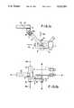
- FIG. 3there is in the upper part of a ground stand 16 a linkage parallelogram 18 which exhibits a plurality of rods which are connected to one another by means of linkages 12a-12d. Moreover, a plate 20 is shown, which exhibits inter alia the linkage 12b.
- An energystoring element 11, known per se--for example a compressed-gas spring--is connected on the one hand to the upper rod of the parallelogram and on the other hand to the plate 20. This energy-storing element 11 applies the required counterbalancing force which is required for the setting of an equilibrium condition upon alteration of the so-called elevation, i.e. in the vertical direction.
- This compensation of the changing energyis effected by an additional component according to the invention for the linkage parallelogram. This is explained in greater detail in FIGS. 4 and 5a-5c.
- the required compensation of the changing energyis achieved by an angle-dependent alteration of position of the suspension of the energy-storing element 11 in the plate 20.
- the compressed-gas spring 11engages via a pin 14 into a slot 13.
- the slotis designed as a circular-arcuate elongate hole and ensures the guiding of the pin 14 as a function of the elevation of the linkage parallelogram 18.
- the length of the slotis determined according to the energy changes--which are to be compensated--of the energy-storing element 11.
- FIG. 5ashows that at maximum lowering (reduction of the elevation) of the linkage parallelogram the pin 14 comes to lie in the upper end-stop region of the slot 13, while this lies in the lower end-stop region of the slot 13 at maximum elevation - cf.
- FIG. 5bshows the middle position, as is evident, for example, from FIG. 4 (horizontal extent of the two rods of the linkage parallelogram 18).
- the function of this accessory device according to the inventionis the following: the pivot arm or the linkage parallelogram 18 is operated during the operation in the course of the setting of the height of the microscope (elevation).
- the energy-storing element 11in this case the compressed-gas spring, has an energy which acts in the direction of its suspension in the plate 20 (i.e. in the direction towards the pin 14).
- the length of the perpendicular between this energy direction and the linkage 12ais that lever arm which is of decisive importance as to the question of whether the pivot arm or the linkage parallelogram 18 does or does not remain in the once set elevation (suspension).
- the linkage parallelogram 18In the active position, the linkage parallelogram 18 can be moved from the horizontal through approximately 35° upwardly (cf. FIG. 5c) and downwardly (cf. FIG.
- the proposed solutions according to the inventionhave made possible a low-effort as well as a very precise orientation of the microscope in height over the field of operation. This leads to a more intense concentration of the surgeon carrying out, for example, a micro-operation on his actual main task, and thus to a shortening of the total manipulation in vivo.
Landscapes
- Engineering & Computer Science (AREA)
- General Engineering & Computer Science (AREA)
- Mechanical Engineering (AREA)
- Health & Medical Sciences (AREA)
- Surgery (AREA)
- Physics & Mathematics (AREA)
- Life Sciences & Earth Sciences (AREA)
- Optics & Photonics (AREA)
- Medical Informatics (AREA)
- Pathology (AREA)
- Nuclear Medicine, Radiotherapy & Molecular Imaging (AREA)
- General Physics & Mathematics (AREA)
- Biomedical Technology (AREA)
- Heart & Thoracic Surgery (AREA)
- Oral & Maxillofacial Surgery (AREA)
- Molecular Biology (AREA)
- Animal Behavior & Ethology (AREA)
- General Health & Medical Sciences (AREA)
- Public Health (AREA)
- Veterinary Medicine (AREA)
- Microscoopes, Condenser (AREA)
Abstract
Description
______________________________________ List of Reference Symbols ______________________________________ 1 Apparatus (for example, Operating microscope) 2Supporting device 3; 4 Adjusting devices (spindle drives) 3a; 3b Double arrows (translation direction indicators) 5Supporting arm 6Carriage 7Guide 8Spindle 8a Double arrow (translation direction indicators) 8b Translation axis of (6) and (7) 9 Rotary bearing 10 Supporting arm 11 Energy-storing element (Compressed- gas spring) 12a, 12b, 12c, 12dLinkages 13Slot 14Pin 15Liquid container 16 Ground stand 18Linkage parallelogram 19Liquid 20 Plate A-A (first) non-vertical axis B-B (second) non-vertical axis ______________________________________
Claims (10)
Applications Claiming Priority (2)
| Application Number | Priority Date | Filing Date | Title |
|---|---|---|---|
| DE3921857 | 1989-07-04 | ||
| DE3921857ADE3921857A1 (en) | 1989-07-04 | 1989-07-04 | TRIPOD EQUIPPED WITH ADDITIONAL DEVICES FOR THE MOUNTING OF A FREELY POSITIONABLE DEVICE |
Publications (1)
| Publication Number | Publication Date |
|---|---|
| US5213293Atrue US5213293A (en) | 1993-05-25 |
Family
ID=6384201
Family Applications (1)
| Application Number | Title | Priority Date | Filing Date |
|---|---|---|---|
| US07/681,503Expired - LifetimeUS5213293A (en) | 1989-07-04 | 1990-07-04 | Stand equipped with accessory devices for supporting a freely orientable apparatus |
Country Status (5)
| Country | Link |
|---|---|
| US (1) | US5213293A (en) |
| EP (1) | EP0433426B1 (en) |
| JP (1) | JPH0747998B2 (en) |
| DE (2) | DE3921857A1 (en) |
| WO (1) | WO1991000472A1 (en) |
Cited By (58)
| Publication number | Priority date | Publication date | Assignee | Title |
|---|---|---|---|---|
| US5351925A (en)* | 1990-07-18 | 1994-10-04 | Deemed International | Device for supporting and positioning a microscope |
| US5383637A (en)* | 1992-10-08 | 1995-01-24 | Carl-Zeiss-Stiftung | Coupling for connecting a surgical microscope to a stand |
| US5435515A (en)* | 1992-09-15 | 1995-07-25 | Garrett W. Brown | Adustable, iso-elastic support apparatus |
| US5492296A (en)* | 1992-09-21 | 1996-02-20 | Carl-Zeiss-Stiftung | Adjustable stand for an optical viewing apparatus |
| US5579071A (en)* | 1994-03-21 | 1996-11-26 | Garrett W. Brown | Camera stabilizing support |
| US5667186A (en)* | 1993-06-21 | 1997-09-16 | Carl-Zeiss-Stiftung | Stand for mounting various loads |
| US5738316A (en)* | 1995-04-03 | 1998-04-14 | Ergotron, Inc. | Vertical work center |
| WO1999001693A1 (en) | 1997-06-30 | 1999-01-14 | Leica Mikroskopie Systeme Ag | Counterweight for stands |
| US6247951B1 (en) | 1998-05-29 | 2001-06-19 | Delphi Technologies, Inc. | Flexible circuit connector |
| EP1152182A1 (en) | 2000-04-25 | 2001-11-07 | Möller-Wedel GmbH | Surgical microscope |
| EP1184615A1 (en)* | 2000-08-29 | 2002-03-06 | Leica Microsystems AG | Supporting device |
| US20020108874A1 (en)* | 2000-09-28 | 2002-08-15 | Leica Microsystems Ag | Stand |
| US20030001057A1 (en)* | 1996-06-07 | 2003-01-02 | Ergotron, Inc. | Pivot assembly and support system |
| US6523796B2 (en)* | 2000-10-19 | 2003-02-25 | Carl-Zeiss-Stiftung | Pivot mounting assembly |
| US20030094549A1 (en)* | 2001-11-19 | 2003-05-22 | Hartmut Gaertner | Arrangement and method for at least partially compensating a torque caused by gravitational forces acting on a mass body |
| US20030101677A1 (en)* | 2000-07-12 | 2003-06-05 | Hewett Frank W. | Joining system for tubular members |
| US20030117703A1 (en)* | 2001-12-21 | 2003-06-26 | Andrzej Metelski | Apparatus for retaining an optical viewing device |
| US6592086B1 (en)* | 2001-07-06 | 2003-07-15 | Leica Microsystems Ag | Microscope stand having X-Y-Z adjustment unit |
| US20030187749A1 (en)* | 2001-03-28 | 2003-10-02 | Ariel Peled | Method and system for creation, management and analysis of distribution syndicates |
| US6732988B2 (en)* | 1999-12-01 | 2004-05-11 | Instrumentarium Corp. | Articulated arm system for supporting medical imaging devices |
| US20040094676A1 (en)* | 2002-07-29 | 2004-05-20 | Cuomo Gerard M. | Surgical microscope apparatus |
| US20040113029A1 (en)* | 2002-12-17 | 2004-06-17 | Piontkowski Paul K. | Head manipulable binocular microscope support |
| US20050040296A1 (en)* | 2003-08-20 | 2005-02-24 | Vincente Rosa | Tire display apparatus |
| US20050213203A1 (en)* | 2004-03-26 | 2005-09-29 | Leica Microsystems Wetzlar Gmbh | Microscope and focusing device for a microscope |
| US20050224670A1 (en)* | 2004-04-12 | 2005-10-13 | Andrzej Metelski | Stand, in particular for surgical microscopes, having an energy storage element |
| US20050224664A1 (en)* | 2004-04-12 | 2005-10-13 | Andrzej Metelski | Stand, in particular for surgical microscopes, having an energy storage element |
| US7104512B2 (en)* | 2002-03-08 | 2006-09-12 | Wolfvision Gmbh | Articulated arm especially for a device for optically capturing objects |
| US20060263082A1 (en)* | 2005-04-15 | 2006-11-23 | Brown Garrett W | Equipoising support apparatus |
| US20070080275A1 (en)* | 2005-10-04 | 2007-04-12 | Garrett Brown | Apparatus for hand control, pressure amplification, and stabilization of medical and industrial devices |
| DE19529549B4 (en)* | 1994-08-26 | 2007-10-18 | Carl Zeiss | Optical therapy and / or diagnostic instrument, in particular surgical microscope |
| US7420731B2 (en) | 2004-12-14 | 2008-09-02 | Piontkowski Paul K | Surgical microscope support system |
| US20080237413A1 (en)* | 2005-11-10 | 2008-10-02 | Hermann Hammer | Holding arrangement having a weight balance |
| US20090219613A1 (en)* | 2008-02-28 | 2009-09-03 | Stefan Enge | Balancing apparatus for a surgical microscope |
| US20090218455A1 (en)* | 2008-02-28 | 2009-09-03 | Andrzej Metelski | Balancing apparatus for a surgical microscope |
| EP1721581A4 (en)* | 2004-03-03 | 2010-12-01 | Olympus Corp | Operating microscope |
| USD634344S1 (en)* | 2009-06-26 | 2011-03-15 | Carl Zeiss Surgical Gmbh | Combination of a stand and an assembly connected thereto of an XY-coupling supporting a carrier arm holding a housing containing one or two microscope bodies equipped with oculars |
| CN102307709A (en)* | 2010-04-28 | 2012-01-04 | 丰田自动车株式会社 | Support arm |
| US20120037785A1 (en)* | 2010-08-12 | 2012-02-16 | Movcam Tech. Co., Ltd. | Spring arm device |
| US20120088963A1 (en)* | 2010-06-10 | 2012-04-12 | Olympus Medical Systems Corp. | Endoscope holding apparatus |
| US20120192382A1 (en)* | 2011-01-31 | 2012-08-02 | Weber Knapp Company | Counterbalance mechanism |
| US20120223199A1 (en)* | 2011-03-01 | 2012-09-06 | Omid Abri | Adjustable holding apparatus for an endoscope |
| CN103202730A (en)* | 2012-01-11 | 2013-07-17 | 徕卡显微系统(瑞士)股份公司 | Stand For Holding At Least One Medical Device, In Particular A Microscope |
| CN103239294A (en)* | 2012-02-14 | 2013-08-14 | 徕卡显微系统(瑞士)股份公司 | Adjustable stand |
| US8584994B2 (en)* | 2011-10-21 | 2013-11-19 | Endure Medical, Inc. | Floor stand with angled arm for microscope |
| US20130327902A1 (en)* | 2012-06-06 | 2013-12-12 | Leica Microsystems (Schweiz) Ag | Stand |
| US8777934B1 (en)* | 2009-12-22 | 2014-07-15 | Western Digital Technologies, Inc. | Balancer swivel arm assembly |
| CN104749759A (en)* | 2015-03-23 | 2015-07-01 | 周艳松 | Adjustable outdoor microcosmic image observation and acquisition system |
| US20160116108A1 (en)* | 2011-03-18 | 2016-04-28 | GCX Corporation | Variable height arm structures, systems, and methods |
| US9364290B2 (en)* | 2013-02-19 | 2016-06-14 | Koh Young Technology Inc. | Stand for a medical-optical instrument |
| CN105759416A (en)* | 2016-05-13 | 2016-07-13 | 镇江市新天医疗器械有限公司 | Oral microscope suspension mechanism |
| CN105759415A (en)* | 2016-05-13 | 2016-07-13 | 镇江市新天医疗器械有限公司 | Operating microscope mounting rack |
| CN105759413A (en)* | 2016-05-13 | 2016-07-13 | 镇江市新天医疗器械有限公司 | Microscope suspension arm |
| CN105807414A (en)* | 2016-05-13 | 2016-07-27 | 镇江市新天医疗器械有限公司 | Oral cavity microscope installation frame |
| WO2016154708A1 (en)* | 2015-03-31 | 2016-10-06 | Centre For Imaging Technology Commercialization (Cimtec) | A counterbalance system and/or a method for counterbalancing a load |
| CN106053417A (en)* | 2016-07-21 | 2016-10-26 | 中国科学院苏州生物医学工程技术研究所 | Two-photon microscope and clinic treatment device |
| US9534730B2 (en) | 2010-08-26 | 2017-01-03 | Garrett W. Brown | Multi-arm gimbal system |
| US10197218B2 (en)* | 2016-11-17 | 2019-02-05 | Samsung Medison Co., Ltd. | Medical apparatus, and display supporting structure and arm structure used in the same |
| US10208888B1 (en)* | 2017-09-14 | 2019-02-19 | Facebook, Inc. | Ergonomic tablet holder |
Families Citing this family (17)
| Publication number | Priority date | Publication date | Assignee | Title |
|---|---|---|---|---|
| FR2706980B1 (en)* | 1993-06-24 | 1995-09-15 | Trophy Radiologie | |
| DE19654302A1 (en)* | 1996-12-24 | 1998-06-25 | Moeller J D Optik | Suspension for a surgical microscope |
| DE19711572B4 (en)* | 1997-03-20 | 2006-09-07 | Carl Zeiss | Surgical microscope stand |
| DE19742048B4 (en)* | 1997-09-24 | 2006-10-19 | Carl Zeiss | Tripod with a linear slide / swivel unit as adjusting device |
| DE19742050B4 (en)* | 1997-09-24 | 2008-07-31 | Carl Zeiss | Tripod with weight compensation |
| US6105909A (en)* | 1997-09-24 | 2000-08-22 | Carl-Zeiss-Stiftung | Stand with energy storage device for weight equalization |
| DE19856696B4 (en)* | 1998-01-19 | 2010-07-29 | Carl Zeiss | Tripod with an adjustment unit |
| JP4521576B2 (en)* | 2000-05-26 | 2010-08-11 | マニー株式会社 | Dental equipment support equipment |
| DE20019105U1 (en) | 2000-11-12 | 2001-05-23 | Leica Microsystems Ag, Heerbrugg | tripod |
| DE20019109U1 (en) | 2000-11-12 | 2001-02-22 | Leica Microsystems Ag, Heerbrugg | Tripod, especially for surgical microscopes |
| WO2012053513A1 (en)* | 2010-10-22 | 2012-04-26 | オリンパスメディカルシステムズ株式会社 | Balance arm |
| JP6440527B2 (en)* | 2015-02-27 | 2018-12-19 | 日本光電工業株式会社 | Link mechanism of arm part |
| EP3061494A1 (en)* | 2015-02-27 | 2016-08-31 | Nihon Kohden Corporation | Link mechanism for arm portion |
| CN105796191B (en)* | 2016-05-13 | 2018-01-23 | 镇江市新天医疗器械有限公司 | A kind of surgical operation microscope hitch |
| CN106499921B (en)* | 2016-11-01 | 2019-04-16 | 芜湖光荣网络科技有限公司 | A kind of intelligence control system of personal nursing beauty instrument |
| KR102000206B1 (en)* | 2019-04-10 | 2019-07-15 | 주식회사 스카 | Apparatus for adjusting of sensor position |
| WO2022128991A1 (en)* | 2020-12-15 | 2022-06-23 | Magventure A/S | A balancing, positioning and fixating assembly |
Citations (10)
| Publication number | Priority date | Publication date | Assignee | Title |
|---|---|---|---|---|
| US3376007A (en)* | 1966-01-28 | 1968-04-02 | Sanders Associates Inc | Holding device |
| US4166602A (en)* | 1978-05-18 | 1979-09-04 | Pennwalt Corporation | Counterbalancing mechanism for X-ray tubeheads |
| US4208028A (en)* | 1974-09-16 | 1980-06-17 | Garrett Brown | Support apparatus |
| EP0023004A1 (en)* | 1979-07-24 | 1981-01-28 | Contraves Ag | Additional arrangement on a support for an optical observation apparatus |
| EP0023003A1 (en)* | 1979-07-24 | 1981-01-28 | Contraves Ag | Arrangement on a support for an optical observation apparatus |
| GB2074337A (en)* | 1980-04-15 | 1981-10-28 | Univ Technology | Adjustable support for an optical or other instrument |
| EP0048404A1 (en)* | 1980-09-18 | 1982-03-31 | Firma Carl Zeiss | Adjustable stand for optical observing units |
| GB2176764A (en)* | 1985-05-28 | 1987-01-07 | Storz Instr Co | Counter-balancing microscope assembly |
| DE3728527A1 (en)* | 1986-08-23 | 1988-03-03 | Olympus Optical Co | TILTING DEVICE FOR SURGICAL MICROSCOPE |
| DE8909957U1 (en)* | 1988-08-19 | 1990-01-11 | MICROCOMPUTER ACCESSORIES INC., Los Angeles, Calif. | Adjustable support frame for screen monitors or similar. |
Family Cites Families (2)
| Publication number | Priority date | Publication date | Assignee | Title |
|---|---|---|---|---|
| JPS495332A (en)* | 1972-05-01 | 1974-01-18 | ||
| JPS5120547U (en)* | 1974-07-31 | 1976-02-14 |
- 1989
- 1989-07-04DEDE3921857Apatent/DE3921857A1/ennot_activeWithdrawn
- 1990
- 1990-07-04JPJP2509965Apatent/JPH0747998B2/ennot_activeExpired - Fee Related
- 1990-07-04DEDE90910672Tpatent/DE59004511D1/ennot_activeExpired - Fee Related
- 1990-07-04EPEP90910672Apatent/EP0433426B1/ennot_activeExpired - Lifetime
- 1990-07-04WOPCT/EP1990/001075patent/WO1991000472A1/enactiveIP Right Grant
- 1990-07-04USUS07/681,503patent/US5213293A/ennot_activeExpired - Lifetime
Patent Citations (11)
| Publication number | Priority date | Publication date | Assignee | Title |
|---|---|---|---|---|
| US3376007A (en)* | 1966-01-28 | 1968-04-02 | Sanders Associates Inc | Holding device |
| US4208028A (en)* | 1974-09-16 | 1980-06-17 | Garrett Brown | Support apparatus |
| US4166602A (en)* | 1978-05-18 | 1979-09-04 | Pennwalt Corporation | Counterbalancing mechanism for X-ray tubeheads |
| EP0023004A1 (en)* | 1979-07-24 | 1981-01-28 | Contraves Ag | Additional arrangement on a support for an optical observation apparatus |
| EP0023003A1 (en)* | 1979-07-24 | 1981-01-28 | Contraves Ag | Arrangement on a support for an optical observation apparatus |
| US4344595A (en)* | 1979-07-24 | 1982-08-17 | Contraves Ag | Auxiliary apparatus at a stand for an optical observation device |
| GB2074337A (en)* | 1980-04-15 | 1981-10-28 | Univ Technology | Adjustable support for an optical or other instrument |
| EP0048404A1 (en)* | 1980-09-18 | 1982-03-31 | Firma Carl Zeiss | Adjustable stand for optical observing units |
| GB2176764A (en)* | 1985-05-28 | 1987-01-07 | Storz Instr Co | Counter-balancing microscope assembly |
| DE3728527A1 (en)* | 1986-08-23 | 1988-03-03 | Olympus Optical Co | TILTING DEVICE FOR SURGICAL MICROSCOPE |
| DE8909957U1 (en)* | 1988-08-19 | 1990-01-11 | MICROCOMPUTER ACCESSORIES INC., Los Angeles, Calif. | Adjustable support frame for screen monitors or similar. |
Non-Patent Citations (3)
| Title |
|---|
| Wild Company brochure, Vl. 89 of Nov. 1986.* |
| Zeiss brochure W 30 082 d of May 1988.* |
| Zeiss brochure W 30-082-d of May 1988. |
Cited By (85)
| Publication number | Priority date | Publication date | Assignee | Title |
|---|---|---|---|---|
| US5351925A (en)* | 1990-07-18 | 1994-10-04 | Deemed International | Device for supporting and positioning a microscope |
| US5435515A (en)* | 1992-09-15 | 1995-07-25 | Garrett W. Brown | Adustable, iso-elastic support apparatus |
| US5492296A (en)* | 1992-09-21 | 1996-02-20 | Carl-Zeiss-Stiftung | Adjustable stand for an optical viewing apparatus |
| US5383637A (en)* | 1992-10-08 | 1995-01-24 | Carl-Zeiss-Stiftung | Coupling for connecting a surgical microscope to a stand |
| US5667186A (en)* | 1993-06-21 | 1997-09-16 | Carl-Zeiss-Stiftung | Stand for mounting various loads |
| US5579071A (en)* | 1994-03-21 | 1996-11-26 | Garrett W. Brown | Camera stabilizing support |
| DE19529549B4 (en)* | 1994-08-26 | 2007-10-18 | Carl Zeiss | Optical therapy and / or diagnostic instrument, in particular surgical microscope |
| US5738316A (en)* | 1995-04-03 | 1998-04-14 | Ergotron, Inc. | Vertical work center |
| US20030001057A1 (en)* | 1996-06-07 | 2003-01-02 | Ergotron, Inc. | Pivot assembly and support system |
| WO1999001693A1 (en) | 1997-06-30 | 1999-01-14 | Leica Mikroskopie Systeme Ag | Counterweight for stands |
| US6247673B1 (en) | 1997-06-30 | 2001-06-19 | Leica Microsystems Ag | Counterweight for stands |
| US6247951B1 (en) | 1998-05-29 | 2001-06-19 | Delphi Technologies, Inc. | Flexible circuit connector |
| US6732988B2 (en)* | 1999-12-01 | 2004-05-11 | Instrumentarium Corp. | Articulated arm system for supporting medical imaging devices |
| EP1152182A1 (en) | 2000-04-25 | 2001-11-07 | Möller-Wedel GmbH | Surgical microscope |
| US6471165B2 (en) | 2000-04-25 | 2002-10-29 | Moller-Wedel Gmbh | Surgical microscope and stand assembly |
| US20030101677A1 (en)* | 2000-07-12 | 2003-06-05 | Hewett Frank W. | Joining system for tubular members |
| US6543914B2 (en) | 2000-08-29 | 2003-04-08 | Leica Microsystems Ag | Stand arrangement |
| EP1184615A1 (en)* | 2000-08-29 | 2002-03-06 | Leica Microsystems AG | Supporting device |
| US6763286B2 (en)* | 2000-09-28 | 2004-07-13 | Leica Microsystems (Schweiz ) Ag | Stand |
| US20020108874A1 (en)* | 2000-09-28 | 2002-08-15 | Leica Microsystems Ag | Stand |
| EP1199508A3 (en)* | 2000-10-19 | 2004-04-21 | Carl Zeiss | Tilting supporting device |
| US6523796B2 (en)* | 2000-10-19 | 2003-02-25 | Carl-Zeiss-Stiftung | Pivot mounting assembly |
| US20030187749A1 (en)* | 2001-03-28 | 2003-10-02 | Ariel Peled | Method and system for creation, management and analysis of distribution syndicates |
| US6592086B1 (en)* | 2001-07-06 | 2003-07-15 | Leica Microsystems Ag | Microscope stand having X-Y-Z adjustment unit |
| US7641155B2 (en) | 2001-11-19 | 2010-01-05 | Carl-Zeiss-Stiftung | Arrangement and method for at least partially compensating a torque caused by gravitational forces acting on a mass body |
| US20030094549A1 (en)* | 2001-11-19 | 2003-05-22 | Hartmut Gaertner | Arrangement and method for at least partially compensating a torque caused by gravitational forces acting on a mass body |
| US20030117703A1 (en)* | 2001-12-21 | 2003-06-26 | Andrzej Metelski | Apparatus for retaining an optical viewing device |
| US7158292B2 (en)* | 2001-12-21 | 2007-01-02 | Leica Microsystems (Schweiz) Ag | Apparatus for retaining an optical viewing device |
| US7104512B2 (en)* | 2002-03-08 | 2006-09-12 | Wolfvision Gmbh | Articulated arm especially for a device for optically capturing objects |
| US20040094676A1 (en)* | 2002-07-29 | 2004-05-20 | Cuomo Gerard M. | Surgical microscope apparatus |
| US7207531B2 (en)* | 2002-12-17 | 2007-04-24 | Piontkowski Paul K | Head manipulable binocular microscope support |
| US20040113029A1 (en)* | 2002-12-17 | 2004-06-17 | Piontkowski Paul K. | Head manipulable binocular microscope support |
| US20050040296A1 (en)* | 2003-08-20 | 2005-02-24 | Vincente Rosa | Tire display apparatus |
| EP1721581A4 (en)* | 2004-03-03 | 2010-12-01 | Olympus Corp | Operating microscope |
| US7088505B2 (en)* | 2004-03-26 | 2006-08-08 | Leica Microsystems Cms Gmbh | Microscope and focusing device for a microscope |
| US20050213203A1 (en)* | 2004-03-26 | 2005-09-29 | Leica Microsystems Wetzlar Gmbh | Microscope and focusing device for a microscope |
| US20050224670A1 (en)* | 2004-04-12 | 2005-10-13 | Andrzej Metelski | Stand, in particular for surgical microscopes, having an energy storage element |
| US20050224664A1 (en)* | 2004-04-12 | 2005-10-13 | Andrzej Metelski | Stand, in particular for surgical microscopes, having an energy storage element |
| US7255311B2 (en)* | 2004-04-12 | 2007-08-14 | Leica Microsystems (Schweiz) Ag | Stand, in particular for surgical microscopes, having an energy storage element |
| US7420731B2 (en) | 2004-12-14 | 2008-09-02 | Piontkowski Paul K | Surgical microscope support system |
| CN101287945B (en)* | 2005-04-15 | 2012-01-25 | 加勒特·W·布朗 | Balance support device |
| WO2006113416A3 (en)* | 2005-04-15 | 2008-01-24 | Garrett W Brown | Equipoising support apparatus |
| US7618016B2 (en) | 2005-04-15 | 2009-11-17 | Brown Garrett W | Equipoising support apparatus |
| US20100059652A1 (en)* | 2005-04-15 | 2010-03-11 | Brown Garrett W | Equipoising support apparatus |
| US20060263082A1 (en)* | 2005-04-15 | 2006-11-23 | Brown Garrett W | Equipoising support apparatus |
| US8066251B2 (en) | 2005-04-15 | 2011-11-29 | Brown Garrett W | Equipoising support apparatus |
| US8342467B2 (en)* | 2005-10-04 | 2013-01-01 | Eric Ronald Stachowski | Apparatus for hand control, pressure amplification, and stabilization of medical and industrial devices |
| US20070080275A1 (en)* | 2005-10-04 | 2007-04-12 | Garrett Brown | Apparatus for hand control, pressure amplification, and stabilization of medical and industrial devices |
| US20080237413A1 (en)* | 2005-11-10 | 2008-10-02 | Hermann Hammer | Holding arrangement having a weight balance |
| US8205845B2 (en) | 2005-11-10 | 2012-06-26 | Carl Zeiss Meditec Ag | Holding arrangement having a weight balance |
| US20090219613A1 (en)* | 2008-02-28 | 2009-09-03 | Stefan Enge | Balancing apparatus for a surgical microscope |
| US20090218455A1 (en)* | 2008-02-28 | 2009-09-03 | Andrzej Metelski | Balancing apparatus for a surgical microscope |
| US8416492B2 (en)* | 2008-02-28 | 2013-04-09 | Leica Instruments (Singapore) Pte. Ltd. | Balancing apparatus for a surgical microscope |
| USD634344S1 (en)* | 2009-06-26 | 2011-03-15 | Carl Zeiss Surgical Gmbh | Combination of a stand and an assembly connected thereto of an XY-coupling supporting a carrier arm holding a housing containing one or two microscope bodies equipped with oculars |
| US8777934B1 (en)* | 2009-12-22 | 2014-07-15 | Western Digital Technologies, Inc. | Balancer swivel arm assembly |
| CN102307709A (en)* | 2010-04-28 | 2012-01-04 | 丰田自动车株式会社 | Support arm |
| US20120088963A1 (en)* | 2010-06-10 | 2012-04-12 | Olympus Medical Systems Corp. | Endoscope holding apparatus |
| US8858423B2 (en)* | 2010-06-10 | 2014-10-14 | Olympus Medical Systems Corp. | Endoscope holding apparatus |
| US20120037785A1 (en)* | 2010-08-12 | 2012-02-16 | Movcam Tech. Co., Ltd. | Spring arm device |
| US9534730B2 (en) | 2010-08-26 | 2017-01-03 | Garrett W. Brown | Multi-arm gimbal system |
| US20120192382A1 (en)* | 2011-01-31 | 2012-08-02 | Weber Knapp Company | Counterbalance mechanism |
| US8899540B2 (en)* | 2011-01-31 | 2014-12-02 | Weber Knapp Company | Counterbalance mechanism |
| US20120223199A1 (en)* | 2011-03-01 | 2012-09-06 | Omid Abri | Adjustable holding apparatus for an endoscope |
| US8870141B2 (en)* | 2011-03-01 | 2014-10-28 | Karl Storz Gmbh & Co. Kg | Adjustable holding apparatus for an endoscope |
| US9759371B2 (en)* | 2011-03-18 | 2017-09-12 | GCX Corporation | Variable height arm structures, systems, and methods |
| US20160116108A1 (en)* | 2011-03-18 | 2016-04-28 | GCX Corporation | Variable height arm structures, systems, and methods |
| US8584994B2 (en)* | 2011-10-21 | 2013-11-19 | Endure Medical, Inc. | Floor stand with angled arm for microscope |
| CN103202730A (en)* | 2012-01-11 | 2013-07-17 | 徕卡显微系统(瑞士)股份公司 | Stand For Holding At Least One Medical Device, In Particular A Microscope |
| CN103202730B (en)* | 2012-01-11 | 2015-09-30 | 徕卡显微系统(瑞士)股份公司 | For keeping at least one medical treatment device, particularly microscopical frame |
| CN103239294A (en)* | 2012-02-14 | 2013-08-14 | 徕卡显微系统(瑞士)股份公司 | Adjustable stand |
| US20130206934A1 (en)* | 2012-02-14 | 2013-08-15 | Leica Microsystems (Schweiz) Ag | Adjustable Stand |
| US20130327902A1 (en)* | 2012-06-06 | 2013-12-12 | Leica Microsystems (Schweiz) Ag | Stand |
| US9364290B2 (en)* | 2013-02-19 | 2016-06-14 | Koh Young Technology Inc. | Stand for a medical-optical instrument |
| CN104749759A (en)* | 2015-03-23 | 2015-07-01 | 周艳松 | Adjustable outdoor microcosmic image observation and acquisition system |
| WO2016154708A1 (en)* | 2015-03-31 | 2016-10-06 | Centre For Imaging Technology Commercialization (Cimtec) | A counterbalance system and/or a method for counterbalancing a load |
| CN105759416A (en)* | 2016-05-13 | 2016-07-13 | 镇江市新天医疗器械有限公司 | Oral microscope suspension mechanism |
| CN105807414A (en)* | 2016-05-13 | 2016-07-27 | 镇江市新天医疗器械有限公司 | Oral cavity microscope installation frame |
| CN105759413A (en)* | 2016-05-13 | 2016-07-13 | 镇江市新天医疗器械有限公司 | Microscope suspension arm |
| CN105759415A (en)* | 2016-05-13 | 2016-07-13 | 镇江市新天医疗器械有限公司 | Operating microscope mounting rack |
| CN105807414B (en)* | 2016-05-13 | 2018-02-16 | 镇江市新天医疗器械有限公司 | A kind of oral cavity microscope mounting bracket |
| CN105759413B (en)* | 2016-05-13 | 2018-04-03 | 镇江市新天医疗器械有限公司 | A kind of microscope suspension arm |
| CN105759415B (en)* | 2016-05-13 | 2018-04-03 | 镇江市新天医疗器械有限公司 | A kind of surgical operation microscope mounting bracket |
| CN106053417A (en)* | 2016-07-21 | 2016-10-26 | 中国科学院苏州生物医学工程技术研究所 | Two-photon microscope and clinic treatment device |
| US10197218B2 (en)* | 2016-11-17 | 2019-02-05 | Samsung Medison Co., Ltd. | Medical apparatus, and display supporting structure and arm structure used in the same |
| US10208888B1 (en)* | 2017-09-14 | 2019-02-19 | Facebook, Inc. | Ergonomic tablet holder |
Also Published As
| Publication number | Publication date |
|---|---|
| EP0433426B1 (en) | 1994-02-02 |
| WO1991000472A1 (en) | 1991-01-10 |
| JPH04505798A (en) | 1992-10-08 |
| EP0433426A1 (en) | 1991-06-26 |
| JPH0747998B2 (en) | 1995-05-24 |
| DE3921857A1 (en) | 1991-01-17 |
| DE59004511D1 (en) | 1994-03-17 |
Similar Documents
| Publication | Publication Date | Title |
|---|---|---|
| US5213293A (en) | Stand equipped with accessory devices for supporting a freely orientable apparatus | |
| US5173803A (en) | Pivoting device for supporting frames for optical observation equipment | |
| DE10042272B4 (en) | stand arrangement | |
| US8132769B2 (en) | Stand for a surgical microscope | |
| US4277044A (en) | Mechanical counterbalance | |
| US4881709A (en) | Stand mechanism for a medical optical equipment | |
| US5173802A (en) | Counterbalanced supporting frame for a surgical microscope | |
| US4836486A (en) | Adjustable support | |
| US6129319A (en) | Automatically adjustable counterbalanced stand | |
| US3762796A (en) | Adjustable support or stand for an optical observation instrument | |
| US4867405A (en) | Stand mechanism for a medical optical equipment | |
| EP0628290A1 (en) | Stand device of optical instrument for medical use | |
| US4684088A (en) | Support apparatus for an optical observation device | |
| US20020121577A1 (en) | Stand | |
| JPH0468946B2 (en) | ||
| US6646798B2 (en) | Microsurgical microscope system | |
| US6833950B2 (en) | Microsurgical microscope system | |
| US6997425B2 (en) | Stand, in particular for a surgical microscope | |
| US7158292B2 (en) | Apparatus for retaining an optical viewing device | |
| EP0917451B1 (en) | Swivel arm, especially for an operation microscope | |
| US5642220A (en) | Microscope balance compensator | |
| GB1597425A (en) | Mechanisms for supporting loads such as ophthalmic instruments | |
| US20030090790A1 (en) | Surgical microscope | |
| JP3350112B2 (en) | Mechanical control unit for operating microscope combined with pedestal | |
| US20020121579A1 (en) | Stand, in particular for surgical microscopes |
Legal Events
| Date | Code | Title | Description |
|---|---|---|---|
| AS | Assignment | Owner name:LEICA HEERBRUGG AG, SWITZERLAND Free format text:ASSIGNMENT OF ASSIGNORS INTEREST.;ASSIGNORS:MUENTENER, JUERG;GESCHWENTNER, OTTO;METZ, JUERGEN;REEL/FRAME:006063/0020 Effective date:19910308 | |
| STCF | Information on status: patent grant | Free format text:PATENTED CASE | |
| FEPP | Fee payment procedure | Free format text:PAYOR NUMBER ASSIGNED (ORIGINAL EVENT CODE: ASPN); ENTITY STATUS OF PATENT OWNER: LARGE ENTITY | |
| FPAY | Fee payment | Year of fee payment:4 | |
| AS | Assignment | Owner name:LEICA GEOSYSTEMS AG, SWITZERLAND Free format text:CHANGE OF NAME;ASSIGNOR:LEICA HEERBRUGG AG;REEL/FRAME:009367/0391 Effective date:19971104 | |
| AS | Assignment | Owner name:LEICA MIKROSKOPIE SYSTEME AG, SWITZERLAND Free format text:ASSIGNMENT OF ASSIGNORS INTEREST;ASSIGNOR:LEICA GEOSYSTEMS AG;REEL/FRAME:009662/0795 Effective date:19981030 | |
| AS | Assignment | Owner name:LEICA MICROSYSTEMS AG, SWITZERLAND Free format text:CHANGE OF NAME;ASSIGNOR:LEICA MIKROSKOPIE SYSTEME AG;REEL/FRAME:010832/0707 Effective date:19990311 | |
| FPAY | Fee payment | Year of fee payment:8 | |
| FPAY | Fee payment | Year of fee payment:12 | |
| AS | Assignment | Owner name:LEICA MICROSYSTEMS (SCHWEIZ) AG, SWITZERLAND Free format text:CHANGE OF NAME;ASSIGNOR:LEICA MICROSYSTEMS AG;REEL/FRAME:023861/0387 Effective date:20020612 | |
| AS | Assignment | Owner name:LEICA INSTRUMENTS (SINGAPORE) PTE. LTD.,SINGAPORE Free format text:ASSIGNMENT OF ASSIGNORS INTEREST;ASSIGNOR:LEICA MICROSYSTEMS (SCHWEIZ) AG;REEL/FRAME:023882/0171 Effective date:20100119 Owner name:LEICA INSTRUMENTS (SINGAPORE) PTE. LTD., SINGAPORE Free format text:ASSIGNMENT OF ASSIGNORS INTEREST;ASSIGNOR:LEICA MICROSYSTEMS (SCHWEIZ) AG;REEL/FRAME:023882/0171 Effective date:20100119 |