US5213236A - Dispensing valve for packaging - Google Patents
Dispensing valve for packagingDownload PDFInfo
- Publication number
- US5213236A US5213236AUS07/804,086US80408691AUS5213236AUS 5213236 AUS5213236 AUS 5213236AUS 80408691 AUS80408691 AUS 80408691AUS 5213236 AUS5213236 AUS 5213236A
- Authority
- US
- United States
- Prior art keywords
- valve
- valve head
- orifice
- dispensing
- set forth
- Prior art date
- Legal status (The legal status is an assumption and is not a legal conclusion. Google has not performed a legal analysis and makes no representation as to the accuracy of the status listed.)
- Expired - Lifetime
Links
- 238000004806packaging method and processMethods0.000titleclaimsabstractdescription18
- 239000012530fluidSubstances0.000claimsabstractdescription97
- 238000005096rolling processMethods0.000claimsabstractdescription25
- 239000000047productSubstances0.000claimsdescription68
- 238000010276constructionMethods0.000claimsdescription20
- 230000033001locomotionEffects0.000claimsdescription20
- 238000007789sealingMethods0.000claimsdescription17
- 229920002379silicone rubberPolymers0.000claimsdescription14
- 239000004944Liquid Silicone RubberSubstances0.000claimsdescription11
- 230000004044responseEffects0.000claimsdescription10
- 239000012263liquid productSubstances0.000claimsdescription8
- 238000003860storageMethods0.000claimsdescription8
- 230000006835compressionEffects0.000claimsdescription6
- 238000007906compressionMethods0.000claimsdescription6
- 238000004891communicationMethods0.000claimsdescription5
- 239000004945silicone rubberSubstances0.000claimsdescription3
- 239000000463materialSubstances0.000description11
- 230000009471actionEffects0.000description8
- 230000035939shockEffects0.000description6
- 230000008901benefitEffects0.000description5
- 239000000344soapSubstances0.000description5
- 239000007788liquidSubstances0.000description4
- 238000013461designMethods0.000description3
- 230000006870functionEffects0.000description3
- 238000004519manufacturing processMethods0.000description3
- XLYOFNOQVPJJNP-UHFFFAOYSA-NwaterSubstancesOXLYOFNOQVPJJNP-UHFFFAOYSA-N0.000description3
- 239000000853adhesiveSubstances0.000description2
- 230000001070adhesive effectEffects0.000description2
- 239000006071creamSubstances0.000description2
- 230000005489elastic deformationEffects0.000description2
- 238000012986modificationMethods0.000description2
- 230000004048modificationEffects0.000description2
- 230000003020moisturizing effectEffects0.000description2
- 235000014438salad dressingsNutrition0.000description2
- 239000002453shampooSubstances0.000description2
- 239000004909MoisturizerSubstances0.000description1
- 241000405070PercophidaeSpecies0.000description1
- 239000004743PolypropyleneSubstances0.000description1
- 230000002159abnormal effectEffects0.000description1
- 239000006096absorbing agentSubstances0.000description1
- 230000001133accelerationEffects0.000description1
- 239000004480active ingredientSubstances0.000description1
- 230000015572biosynthetic processEffects0.000description1
- 239000003599detergentSubstances0.000description1
- 230000000916dilatatory effectEffects0.000description1
- 235000013305foodNutrition0.000description1
- 230000000977initiatory effectEffects0.000description1
- 238000000034methodMethods0.000description1
- 230000001333moisturizerEffects0.000description1
- 238000000465mouldingMethods0.000description1
- 239000006072pasteSubstances0.000description1
- 239000004033plasticSubstances0.000description1
- -1polypropylenePolymers0.000description1
- 229920001155polypropylenePolymers0.000description1
- 239000000843powderSubstances0.000description1
- 230000008569processEffects0.000description1
- 229920000260silasticPolymers0.000description1
- 239000012265solid productSubstances0.000description1
- 239000000126substanceSubstances0.000description1
- 229920003002synthetic resinPolymers0.000description1
- 239000000057synthetic resinSubstances0.000description1
- 238000012360testing methodMethods0.000description1
- 239000003053toxinSubstances0.000description1
- 231100000765toxinToxicity0.000description1
Images


Classifications
- B—PERFORMING OPERATIONS; TRANSPORTING
- B65—CONVEYING; PACKING; STORING; HANDLING THIN OR FILAMENTARY MATERIAL
- B65D—CONTAINERS FOR STORAGE OR TRANSPORT OF ARTICLES OR MATERIALS, e.g. BAGS, BARRELS, BOTTLES, BOXES, CANS, CARTONS, CRATES, DRUMS, JARS, TANKS, HOPPERS, FORWARDING CONTAINERS; ACCESSORIES, CLOSURES, OR FITTINGS THEREFOR; PACKAGING ELEMENTS; PACKAGES
- B65D35/00—Pliable tubular containers adapted to be permanently or temporarily deformed to expel contents, e.g. collapsible tubes for toothpaste or other plastic or semi-liquid material; Holders therefor
- B—PERFORMING OPERATIONS; TRANSPORTING
- B65—CONVEYING; PACKING; STORING; HANDLING THIN OR FILAMENTARY MATERIAL
- B65D—CONTAINERS FOR STORAGE OR TRANSPORT OF ARTICLES OR MATERIALS, e.g. BAGS, BARRELS, BOTTLES, BOXES, CANS, CARTONS, CRATES, DRUMS, JARS, TANKS, HOPPERS, FORWARDING CONTAINERS; ACCESSORIES, CLOSURES, OR FITTINGS THEREFOR; PACKAGING ELEMENTS; PACKAGES
- B65D47/00—Closures with filling and discharging, or with discharging, devices
- B65D47/04—Closures with discharging devices other than pumps
- B65D47/20—Closures with discharging devices other than pumps comprising hand-operated members for controlling discharge
- B65D47/2018—Closures with discharging devices other than pumps comprising hand-operated members for controlling discharge comprising a valve or like element which is opened or closed by deformation of the container or closure
- B65D47/2031—Closures with discharging devices other than pumps comprising hand-operated members for controlling discharge comprising a valve or like element which is opened or closed by deformation of the container or closure the element being formed by a slit, narrow opening or constrictable spout, the size of the outlet passage being able to be varied by increasing or decreasing the pressure
Definitions
- the present inventionrelates to product packaging, and in particular to a self-sealing valve for fluid products, and the like.
- packages or containersare presently available for packaging non-solid products of the type which are capable of flowing, such as fluid or fluidized materials, including liquids, pastes, powders, and the like, which substances are collectively and generically referred to herein as "fluids".
- Some such packagesinclude a dispenser which permits a selected amount of fluid to be discharged from the package, and then reseals to close the package.
- Self-sealing dispensing valveshave been used in packaging for certain types of products, such as the container disclosed in U.S. Pat. No. 4,728,006 to Drobish et al, which is designed for shampoos, conditioners, and the like.
- such valveshave been known to experience some types of sealing problems, and inconsistent dispensing characteristics, particularly when the packages are exposed to significant temperature variations.
- Valves constructed from most conventional plastic materialscannot be used in at least certain types of packages, since they either react with or adulterate the product. For instance, in food packaging, care must be taken to avoid the use of valve materials which might contain any type of toxin. Furthermore, active ingredients in products can cause the valve to either embrittle or soften, thereby ruining the designed flow rate and/or self-sealing characteristics of the valve.
- Liquid silicone rubber valveshave recently been used in some types of packaging, and have proven particularly advantageous since the material is inherently quite inert, and will therefore not either adulterate or react with the packaged product. Examples of such packaging are provided in applicant's U.S. Pat. No. 5,033,655 to Brown.
- liquid silicone rubberpossesses many attributes for use in packaging, it also has other characteristics which render such applications problematic.
- the surfaces of liquid silicone rubber partsare extremely tacky or sticky, having a very high coefficient of friction.
- the surfaces of the valve flangewill stick tightly to the adjacent surfaces of the container and collar before the collar can be tightened securely enough to create a leak-resistant seal. Tightening of the collar often causes the valve flange, as well as the entire valve to distort from its designed shape, thereby preventing the formation of a secure seal, and/or changing the intended dispensing and sealing characteristics of the valve.
- Another problem experienced with prior dispensing packagesrelates to achieving a proper design balance between the package container, valve, and fluid product, so that the product can be repeatedly dispersed without requiring excess force, and will neatly discharge only that amount of product which is desired by the user, particularly in keeping with the type of product involved. For instance, when dispensing highly concentrated fluid products, such as hand soaps, and the like, the user will typically require only a small amount or dollop of soap per application to achieve satisfactory results. In contrast, when using other types of fluid products, such as skin moisturizers, tanning formulas, and the like, larger quantities of product are typically required by the user for each application.
- the ability of the valve to quickly and readily open in response to moderate pressure on the containeris important, as is the ability of the valve to quickly and securely close when the pressure has been released. Also important is the amount of pressure which must be maintained on the container to sustain fluid through the valve once the valve is opened. The ability to quickly and accurately achieve a proper balance between all of these factors is very desirable in designing dispensing packages.
- One aspect of the present inventionis a dispensing package for fluid products and the like, comprising a container having a dispensing valve mounted therein.
- the dispensing valveincludes a marginal flange which seals about a discharge opening of the container, and a valve head with an orifice therethrough which opens and closes in response to the application and release of a predetermined discharge pressure to control fluid flow therethrough.
- the valveincludes a connector sleeve having one end connected with the valve flange, and an opposite end connected with the valve head adjacent a marginal edge thereof.
- the connector sleevehas a resiliently flexible construction, whereby when pressure within the containers raised above the predetermined discharge pressure, the valve head shifts outwardly in a manner which causes the connector sleeve to double over and then extend rollingly, and thereby apply a torque to the valve head which assists in opening the orifice.
- Another aspect of the present inventionis a dispensing valve for fluid product packaging and the like, having a marginal valve flange shaped to seal about a discharge opening of the container.
- the valveincludes a valve head having a marginal edge, interior and exterior sides, and an orifice extending therebetween which opens to permit fluid flow therethrough in response to communication with a predetermined discharge pressure, and closes to shut off fluid flow therethrough upon removal of the predetermined discharge pressure.
- a connector sleeve with a resiliently flexible constructionhas one end connected with the valve flange, and the opposite end connected with the valve head adjacent to the marginal edge thereof, whereby when pressure in excess of the predetermined discharge pressure is applied to the interior side of the valve head, the valve head shifts outwardly in a manner which causes the connector sleeve to double over and then extend rollingly, and thereby apply a torque to the valve head which assists in opening the orifice.
- Yet another aspect of the present inventionis a dispensing package for fluid products and the like, comprising a container having a dispensing valve mounted therein for controlling the flow of fluid product from the container.
- the dispensing valveincludes a marginal valve flange, a valve head with an orifice which permits fluid flow therethrough, and a connector sleeve having one end connected with the valve flange, and an opposite end connected with the valve head adjacent a marginal edge thereof, such that the dispensing valve assumes a generally hat-shaped, side elevational configuration which normally projects inwardly toward the interior of the container.
- the connector sleevehas a resiliently flexible construction which permits the valve head to shift outwardly through the valve flange by doubling over the connector sleeve, which then extends rollingly outwardly.
- Yet another aspect of the present inventionis a dispensing valve, comprising a marginal valve flange, and a valve head with an orifice therethrough which selectively opens to permit fluid flow in response to communication with a predetermined discharge pressure.
- the valve headis configured such that it assumes a generally convex orientation when the orifice is open.
- the dispensing valvealso includes a connector sleeve, which has a resiliently flexible construction, with one end connected with the valve flange, and an opposite end connected with the valve head adjacent the marginal edge thereof, whereby when pressure in excess of the predetermined discharge pressure is applied to the interior side of the valve head, the valve head shifts outwardly in a manner which causes the connector sleeve to double over and then extend rollingly, and thereby apply a torque to the valve head which resiliently snaps the valve head into its convex orientation to quickly and fully open the orifice.
- Yet another aspect of the present inventionis a self-sealing dispensing valve for fluid product packaging and the like, comprising a marginal valve flange, and a valve head with an orifice therein which selectively permits fluid flow through the valve.
- the interior side of the valve headhas an outwardly curving arcuate side elevational shape defined by a first radius, while the exterior side of the valve head has an outwardly curving arcuate side elevational shape defined by a second radius, which is less than the first radius.
- a connector sleeveis provided with a resiliently flexible construction, and has one end connected with the valve flange, and the opposite end connected with the valve head.
- Yet another aspect of the present inventionis a self-sealing dispensing valve for fluid product packaging and the like, comprising a marginal valve flange, and a valve head having a discharge opening therein to selectively permit fluid flow.
- the valve headincludes a exterior side having an outwardly curving arcuate side elevational shape defined by a first radius, and an interior side with a center portion having a generally flat side elevational shape, and a marginal portion having an outwardly curving arcuate side elevational shape defined by a second radius, which is greater than the first radius.
- the discharge orificeextends from the center portion of the exterior surface to the interior surface of the valve head to achieve easy and complete opening of the discharge orifice when the predetermined discharge pressure is applied thereto, and secure and complete closing of the discharge opening when the predetermined discharge pressure is released.
- Yet another aspect of the present inventionis a dispensing valve for fluid product packaging, comprising a marginal valve flange, and a valve head having an orifice therein which opens to permit fluid flow therethrough in response to a predetermined discharge pressure, and closes to shut off fluid flow therethrough upon removal of the predetermined discharge pressure.
- the dispensing valveincludes a substantially imperforate rolling diaphragm positioned between and interconnecting the valve flange and the valve head, which has a flexible construction which permits the valve head to shift between a retracted position on an interior side of the marginal flange for storage, and an extended position on an exterior side of the marginal flange for dispensing.
- valve headWhen pressure in excess of the discharge pressure is applied to the container, the valve head first shifts to the extended position, and then opens the orifice to discharge the fluid product therethrough. Upon release of the pressure, the orifice first closes to shut off the flow of fluid product therethrough, and the valve head then shifts to the retracted position for storage.
- Yet another aspect of the present inventionis a valve, comprising a marginal valve flange, and a valve head having a marginal edge, interior and exterior sides, and an orifice extending therebetween which in response to communication with a predetermined discharge pressure, shifts to a fully open position to permit fluid flow therethrough.
- a connector sleeveis provided, having a resiliently flexible construction, with one end connected with the valve flange, and an opposite end connected with the valve head adjacent the marginal edge thereof, which permits the valve head to shift with respect to the marginal valve flange in a manner which causes the connector sleeve to double over and then extend rollingly, and thereby apply an outwardly directed torque to the valve head which tends to open the orifice.
- the valve headis configured with a plan shape which expands or dilates as the orifice is shifted to the fully open position, which expansion is resisted by the connector sleeve, so as to inwardly compress the valve head, which inward compression and torque applied to the valve head by the connector sleeve combine to resiliently maintain the orifice in the fully open position, whereby that pressure required to maintain fluid flow through the orifice is substantially less than the predetermined threshold pressure, so as to provide greater ease of dispensing and flow control.
- the principle objects of the present inventionare to provide a dispensing package which is capable of easily and neatly dispensing a wide variety of different types of fluid products.
- the dispensing packageinclude a self-sealing valve which is matched with both the container and the type of fluid product to be dispensed, so as to quickly and securely seal, yet readily and fully open when the user applies modest pressure to the container.
- the valveincludes a resiliently flexible connector sleeve which is configured to double over and then extend rollingly so as to apply a torque to the valve head which assists in opening the orifice.
- the connector sleevehas sufficient flexibility that pressure increases in the interior of the container, such as those caused by thermal expansion, are offset by shifting the valve head on the connector sleeve, so as to alleviate excess pressure on the orifice.
- the connector sleeveis also configured to provide sufficient flexibility that any misalignment and/or distortion of the valve flange when attached to the associated container are not transmitted to the valve head, thereby permitting unhindered opening and closing of the orifice.
- the connector sleeveis also configured to provide sufficient flexibility that shock impact forces, and the like applied to the container are absorbed by shifting the valve head on the connector sleeve, so as to avoid inadvertent opening of the valve orifice.
- the valveis configured to provide a generally constant flow rate therethrough, even when exposed to a relatively wide range of container pressures.
- the valveis configured such that once the orifice is shifted open, the amount of pressure required to maintain fluid flow through the orifice is reduced, so as to provide greater ease of operation, without sacrificing secure sealing of the valve.
- the dispensing packageis extremely versatile, and particularly adapted for use in conjunction with bottom dispensing containers, and other similar packaging.
- the valveis very durable, while having reduced manufacturing costs, and an uncomplicated design.
- the overall packageis efficient in use, economical to manufacture, capable of a long operating life, and particularly well adapted for many different proposed uses.
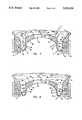
- FIG. 1is a perspective view of a dispensing package embodying the present invention, wherein a portion thereof has been broken away to reveal a self-sealing valve mounted in a bottom portion of an associated container.
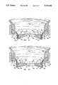
- FIG. 2is a side elevational view of the dispensing package, wherein a portion thereof has been broken away to reveal the valve, which is shown in a fully retracted and fully closed position.
- FIG. 3is a side elevational view of the dispensing package, wherein a portion thereof has been broken away to reveal the valve, which is shown in a fully extended and fully open position.
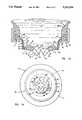
- FIG. 4is an enlarged, fragmentary top view of the valve.
- FIG. 5is an enlarged, side elevational view of the valve.
- FIG. 6is an enlarged, cross-sectional view of the valve.
- FIG. 7is an enlarged, cross-sectional view of the valve installed in an associated container, with the valve shown in the fully closed and fully retracted position.
- FIG. 8is an enlarged, cross-sectional view of the valve installed in an associated container, with the valve shown in a fully closed, and partially retracted position.
- FIG. 9is an enlarged, cross-sectional view of the valve installed in an associated container, with the valve shown in a fully closed and partially extended position.
- FIG. 10is an enlarged, cross-sectional view of the valve installed in an associated container, with the valve shown in a fully closed and fully extended position.
- FIG. 11is an enlarged, cross-sectional view of the valve installed in an associated container, with the valve shown in a fully closed and fully extended position, wherein a valve head portion which is shown beginning to snap outwardly.
- FIG. 12is an enlarged, cross-sectional view of the valve installed in an associated container, with the valve shown in a fully closed, and fully extended position, wherein the valve head portion of which is shown continuing to snap outwardly.
- FIG. 13is an enlarged, cross-sectional view of the valve installed in an associated container, with the valve shown in a fully open, and fully extended position, wherein the valve head portion of which is shown snapped fully outwardly.
- FIG. 14is an enlarged, bottom plan view of the valve shown in the position illustrated in FIG. 13.
- FIG. 15is an enlarged, cross-sectional view of the valve installed in an associated container, with the valve shown in a fully closed, and partially extended position abutting a container closure.
- FIG. 16is an enlarged, cross-sectional view of the valve installed in an associated container, with the valve shown in a fully closed and fully extended position abutting an alternative container closure.
- the reference numeral 1generally designates a dispensing package embodying the present invention.
- Dispensing package 1is particularly adapted for dispensing fluid products, such as liquid soaps, household cleaners, polishes, moisturizing creams, foodstuffs, and the like, and includes a container 2 with a self-sealing dispensing valve 3 mounted therein.
- Valve 3includes a marginal flange 4, a valve head 5 with a discharge orifice 6 therein, and a connector sleeve 7, having one end connected with valve flange 4, and the opposite end connected with valve head 5 adjacent a marginal edge thereof.
- Connector sleeve 7has a resiliently flexible construction, such that when pressure within container 2 is raised above a predetermined amount, valve head 5 shifts outwardly (FIGS. 8-15) in a manner which causes connector sleeve 7 to double over and then extend rollingly.
- the illustrated container 2(FIGS. 1-3) is particularly designed for bottom dispensing, and includes a generally flexible, oblong container body 12 supported on a substantially rigid base 13.
- Container body 12is preferably integrally molded from an appropriate synthetic resin material or the like, so as to create a one-piece construction that includes oppositely oriented sidewalls 14 and 15, a top 16 and a bottom 17.
- the container sidewalls 14 and 15are laterally flexible to pressurize and depressurize the interior of container 2, and preferably have sufficient resilience or stiffness that they automatically return to their original shape upon release of any external forces which are applied to container 2 to dispense a fluid product 18 therefrom.
- the illustrated container bottom 17(FIGS. 2 and 3) includes a downwardly opening neck 20, which defines a discharge opening 21 about which the marginal flange 4 of valve 3 is positioned.
- the free end of neck 20includes an annularly shaped groove 22 having a general L-shaped longitudinal cross-sectional configuration, which is shaped to closely, receive the marginal flange 4 of valve 3 therein.
- Container base 13includes a valve retainer ring 23 positioned adjacent groove 22, and attached to container body 12 by a snap lock arrangement 24.
- Container base 13(FIGS. 2 and 3) has a substantially flat bottom 25 adapted to abuttingly support dispensing package 1 on an associated surface, such as a countertop, sink, worksurface, or the like.
- Neck groove 22is located inwardly of the bottom 25 of container base 13, so as to position valve 3 in a generally recessed condition within dispensing package 1, as explained in greater detail hereinafter.
- valve 3has an integrally formed, one-piece construction.
- Valve 3is preferably molded from a resiliently flexible material, and in the illustrated example comprises a silicone rubber which is substantially inert so as to avoid reaction with and/or adulteration of the fluid product being packaged.
- valve 3is produced at relatively high speeds through the molding of liquid silicone rubber.
- the illustrated marginal flange portion 4 (FIGS. 4-6) of valve 3has an annular plan shape, and a substantially L-shaped cross-sectional configuration, comprising an inner edge 30, an outer edge 31, a bottom 32, and a top 33 with an outer rim 34 upstanding therefrom.
- Marginal valve flange 4has substantial thickness between the bottom 32 and top 33 which is resiliently compressed upon attachment of retainer ring 23 to form a secure leak-resistant seal therebetween.
- the rim portion 34 of valve flange 4positively locks valve 3 in neck groove 22 to prevent any radial movement therebetween.
- valve head portion 5(FIGS. 4-6) of valve 3 has a circular plan shape, and a generally tapered construction which is thicker at the radially outside portion of valve head 5, and thinner at the radially inside portion thereof. This tapered construction assists in achieving the snap open/snap close action of valve 3, as described below. More specifically, in the illustrated example, valve head 5 has an exterior side or surface 38, which has an arcuately shaped side elevational configuration which opens or curves outwardly, toward the exterior of dispensing package 1, and is defined by a first, predetermined radius. Valve head exterior surface 38 extends continuously between the interior sidewalls of connector sleeve 7.
- Valve head 5also includes an interior side or surface 39, which has a marginal portion 40 with an arcuately shaped side elevational configuration which opens or curved outwardly, toward the exterior of dispensing package 1, and is defined by a second predetermined radius.
- the radius of marginal portion 40 on interior surface 39is larger than that of exterior surface 38, such that the two surfaces converge toward the center of valve head 5, and provide the above-noted inwardly tapered construction of valve head 5.
- the interior surface 39 of valve head 5also includes a center portion 41, which has a circular plan shape, with a substantially planar or flat side elevational configuration, oriented generally perpendicularly to discharge orifice 6.
- the center portion 41 of valve head 5assists in improving the opening and closing characteristic of valve 3, as set forth below.
- valve head 5The outer perimeter of valve head 5 is defined by a circular marginal edge 42, which begins at the outer edge 43 of marginal portion 40, and extends outwardly therefrom with a slight outward taper, ultimately merging into connector sleeve 7.
- the intersection of the marginal portion 40 and the center portion 41 of valve head 5defines a circular edge 44.
- the outside diameter of valve head 5, as measured along marginal edge 42is substantially smaller than the inside diameter of marginal flange 4, as measured along inner edge 30. As explained in greater detail below, this spacing between valve head 5 and marginal flange 4 permits valve head 5 to shift freely in an axial direction through the center of marginal flange 4.
- the illustrated connector sleeve portion 7 (FIGS. 4-6) of valve head 5is in the form of a rolling diaphragm, having a hollow circular plan configuration, and a generally J-shaped longitudinal cross-sectional shape, comprising a cylindrical sidewall portion 45, and a radially outwardly extending base portion 46.
- Connector sleeve 7has interior and exterior surfaces 47 and 48 respectively, which are spaced equidistantly apart along the length thereof, such that connector sleeve 7 has a substantially uniform thickness.
- One end portion 49 of connector sleeve 7is connected with the exterior surface 38 of valve head 5 adjacent the marginal edge 42 thereof, and the opposite end portion 50 of connector sleeve 7 is connected with the inner edge 30 of marginal valve flange 4.
- connector sleeve 7 adjacent end 49is positioned substantially coplanar and contiguous with the marginal edge 42 of valve head 5, while the opposite end 50 of connector sleeve 7 is connected with marginal valve flange 7 at a medial portion of inner edge 30, such that the base portion 46 of connector sleeve 7 flares in a radially inwardly direction from marginal valve flange 46, and also protrudes outwardly toward the exterior of dispensing package 1 at an arcuate portion 51 of connector sleeve 7.
- the arcuately flared shape of connector sleeve portion 51assists connector sleeve 7 in first doubling over, and then rollingly extending as valve head 5 shifts outwardly in the manner described in greater detail below.
- the exterior surface 48 of sleeve side wall 45 at end 49 of connector sleeve 7intersects the exterior surface 38 of valve head 5 at an angle which defines a circular edge 52.
- the exteriormost area of sleeve arcuate portion 51is disposed substantially in-line with or slightly interior of the bottom 32 of marginal flange 4, so as to facilitate fabrication.
- the length of connector sleeve 7is preferably selected sufficiently short to prevent the same from folding in behind valve head 5 when valve head 5 is in the fully extended position (FIGS. 10-14), thereby avoiding interference with the retraction of valve head 5, which is explained in detail below.
- the illustrated one-piece valve 3has a hat-shaped side elevational configuration in its original, normal condition, wherein valve head 5 assumes a generally concave shape.
- the resilient flexibility of connector sleeve 7permits the same to double over and then extend rollingly in the manner described hereinafter.
- Connector sleeve 7acts as a rolling diaphragm with valve head 5 mounted at the center thereof in a manner which permits valve head 5 to shift or float freely inwardly and outwardly in an axial direction with respect to the opening 21 in container neck 20.
- discharge orifice 6has a cross-slit construction which includes two, intersecting linear slits 55 and 56 that extend through the opposite sides 38 and 39 of center portion 41.
- the illustrated slits 55 and 56are oriented in a mutually perpendicular relationship, and have their opposite ends 55a and 55b positioned slightly inwardly from the outer edge 44 of center portion 41.
- Orifice slits 55 and 56define four flaps or pedals 57 which flex inwardly and outwardly to selectively permit the flow of fluid product through valve 3.
- Slits 55 and 56are preferably formed by slicing through the center portion 41 of valve head 5, without removing any substantial amount of material therefrom, so that the opposite side faces 58 and 59 (FIGS. 13 and 14) of valve flaps 57 closely seal against one another when discharge orifice 6 is in its normally, fully closed position.
- the length and location of slits 55 and 56can be adjusted to vary the predetermined opening and closing pressures of valve 3, as well as other dispensing characteristics of dispensing package 1.
- the side faces 58 and 59 of each valve flap 57intersect at their free ends to define an end edge 60. That portion of valve head 5 disposed between marginal portion 40, marginal edge 42, slit ends 55a and 55b and exterior surface 38 defines a ring portion 61 of the valve head 5, which functions in the manner described in detail hereinafter.
- orifice 6may assume many different shapes, sizes and/or configurations in accordance with those dispensing characteristics desired.
- orifice 6may comprise a single slit, particularly when smaller or narrower streams are desired.
- Orifice 6may also include three or more slits, particularly when larger or wider streams are desired, and/or the fluid product contains aggregates, such as some types of salad dressings, and the like.
- Other forms of orifices 6, such as holes, duck bills, etc.may also be incorporated into valve 3.
- Self-sealing dispensing valve 3is preferably especially configured for use in conjunction with a particular container 2, and a specific type of fluid product, so as to achieve the exact dispensing characteristics desired.
- the viscosity and density of the fluid productare both important factors in designing the specific configuration of valve 3, as is the shape, size, and strength of container 2, particularly when dispensing package 1 is configured for bottom dispensing.
- the rigidity and durometer of the valve material, and size and shape of both valve head 5 and connector sleeve 7are also important in achieving the desire dispensing characteristics, and should be carefully matched with both the container 2 and fluid material 18 to be dispensed therefrom.
- One working embodiment of the present inventionis particularly designed to dispense fluid household products therefrom, such as dishwasher detergents, liquid soap, moisturizing creams, foodstuffs, and the like.
- fluid product materialssuch as dishwasher detergents, liquid soap, moisturizing creams, foodstuffs, and the like.
- one specific valve 3 found to be particularly suitedis as follows.
- the outside and inside diameters of marginal valve flange 4are 0.7000 and 0.5802 inches respectively, while the outside diameter of the marginal edge 42 of valve head 5 is 0.4391 inches, and the outside diameter of center portion 41 is around 0.2212 inches.
- the thickness of connector sleeve 7is approximately 0.0130 inches, and has an overall height, as measured from the bottom 32 of marginal flange 4 to the edge 52 of valve head 5 of 0.1159 inches.
- the radius of valve head exterior surface 38is 0.2900 inches, while the radius of the marginal portion 40 of interior surface 39 is 0.0350 inches.
- the total thickness of valve head 5 at marginal edge 42is around 0.0778 inches and around 0.0350 inches at the middle of center portion 41.
- the overall height of valve 3, as measured from the bottom 32 of marginal flange 4 to the top of center portion 41is approximately 0.2402 inches.
- Slits 55 and 56have a length of around 0.2200 inches, and are centered squarely in valve center portion 41.
- the valveis molded integrally from a liquid silicone rubber of the type manufactured under the trademark "SILASTIC SR" by Dow Corning Corporation.
- valve 3snaps open when exposed to a pressure inside container 2 equal to approximately, 25-28 inches of water. That pressure which causes valve 3 to snap open is generally referred to herein as the predetermined dispensing or opening pressure. Valve 3 will automatically snap closed when the interior pressure of container 2 drops below a pressure equal to approximately 16-18 inches of water. That pressure which causes valve 3 to snap closed is generally referred to herein as the predetermined closing pressure. While the noted valve 3 is open, a substantially constant flow or stream of fluid product is discharged through orifice 6, even when extra pressure is exerted on container 2.
- valve 3may assume many different shapes and sizes, particularly in keeping with the type of container 2 and fluid product to be dispensed therefrom.
- the predetermined opening and closing pressures of valve 3may be varied widely in accordance with those dispensing criteria desired for a particular product.
- Flow characteristics of the dispensed fluid productcan also be adjusted substantially, such as for relatively wide column-like streams, thin needle-like streams, dollops, and the like.
- dispensing package 1functions in the following manner.
- Valve 3normally assumes the inwardly protruding orientation illustrated in FIG. 7, wherein valve 3 remains substantially in its original molded shape without deformation, with connector sleeve 7 being fully retracted and discharge opening 6 being fully closed.
- valve 3is mounted in the bottom of container 2, as is shown in the illustrated bottom dispensing package 1, valve 3 is configured such that discharge orifice 6 will remain securely closed, even under the hydraulic head pressure applied thereto by the fluid product 18 when the container 2 is completely full.
- connector sleeve 7When additional pressure is communicated with the interior of container 2, such as by manually flexing container sidewalls 14 and 15 inwardly, connector sleeve 7 functions as a rolling diaphragm, and permits valve head 5 to begin shifting axially outwardly toward the exterior of dispensing package 1 by doubling over connector sleeve 7, which then in turn, begins to extend outwardly in a rolling fashion, as illustrated in FIG. 8.
- the outwardly protruding J-shaped configuration of connector sleeve 7assists in initiating this rolling motion of connector sleeve 7.
- the elastic deformation of connector sleeve 7 from its original molded shapeFIG.
- valve 7generates a complex pattern of stresses within valve 3 which resiliently urges the same back into its original or normal configuration, which forces include an outwardly directed torque applied by connector sleeve 7 to valve head 5 adjacent marginal edge 42, which tends to resiliently urge discharge orifice 6 toward its open position, as described in greater detail below.
- valve head 5When additional pressure is communicated with the interior of container 2, as illustrated in FIG. 9, valve head 5 continues to shift axially outwardly by rolling connector sleeve 7 over upon itself.
- the marginal edge 42 of valve head 5passes through the center of marginal valve flange 4.
- valve head 5When additional pressure is communicated with the interior of container 2, valve head 5 continues to extend outwardly toward the exterior of dispensing package 1 until connector sleeve 7 is fully extended, as illustrated in FIG. 10.
- the stress forces built up in connector sleeve 7cause the sidewall portion 45 of the connector sleeve 7 to assume a generally cylindrical shape concentric with and about the marginal edge 42 of valve head 5.
- Sidewall 45 of connector sleeve 7is folded back 180 degrees from its original molded shape, to an orientation parallel with the marginal edge 42 of valve head 5, and defines an exterior lip or rim 65.
- valve head 5When additional pressure is communicated with the interior of container 2, as illustrated in FIG. 11, valve head 5 continues to shift outwardly. However, since connector sleeve 7 is fully extended, further outward shifting of valve head 5 longitudinally tenses or stretches connector sleeve 7, thereby increasing the outwardly directed torque applied to the valve head. 5. Also, the further outward movement of valve head 5 tends to flatten or straighten valve head 5, particularly along the exterior surface 38 thereof, as best illustrated in FIG. 11.
- valve head 5This flattening motion tends to enlarge or dilate the circular plan configuration of valve head 5, which enlargement is in turn resisted by radially inwardly directed forces applied to the marginal edge 42 of valve head 5 by connector sleeve 7, thereby generating another complex pattern of stresses within valve 3, which forces include those which tend to compress valve head 5 in a radially inward direction. Due to the tapered shape of valve head 5, the majority of compression strain is believed to take place adjacent the center portion 41 of valve head 5. As best illustrated by a comparison of the broken line figure and the full line figure provided in FIG.
- valve head 5When additional pressure is communicated with the interior of container 2, as illustrated in FIG. 12, valve head 5 continues to shift outwardly by further longitudinal stretching of connector sleeve 7, and further enlargement of the plan shape of valve head 5. This motion is best illustrated by a comparison of the broken line figure and the full line figure provided in FIG. 12. Exterior rim 65 moves from the condition illustrated in FIG. 11, which corresponds to the broken line figure of FIG. 12, in an axially outwardly and radially outwardly fashion to the position shown in the full lines of FIG. 12. The marginal edge 42 of valve head 5 is shown more bent or elastically deformed inwardly, as a consequence of the increased torque forces applied thereto by connector sleeve 7.
- valve head 5into a state of bifurcation, as illustrated in FIG. 12, wherein the combined forces acting on valve head 5 will, upon application of any additional outward force on the interior side 39 of valve 3, cause the same to quickly open outwardly with a snapping motion to separate valve flaps 57 in the manner illustrated in FIGS. 13 and 14, and thereby dispense liquid product through discharge orifice 6.
- the bifurcation state of valve 3, as the term is used herein,is illustrated in FIG. 12, and defines a relatively unstable condition which valve 3 assumes immediately prior to opening into the fully open condition shown in FIGS. 13 and 14. As valve 3 passes through the bifurcation state shown in FIG.
- valve head 5assumes the shape of a nearly planar disc, with exterior surface 38 cupped inwardly between rim 65 and flap edges 60, and interior surface 39 bent slightly outwardly toward the center of orifice 6.
- valve 3The snap type opening of valve 3 is achieved, at least in part, by the torque exerted on valve head 5 by connector sleeve 7, which as noted in the example illustrated in FIG. 12, is sufficient to substantially distort the shape of the marginal edge 42 of valve head 5.
- valve flaps 57, as well as the associated rim portion 61 of valve head 5are bent or elastically deformed outwardly, thereby permitting the rim 65 of valve head 5 to become smaller or constrict slightly.
- Valve flaps 57tend to fold openly along lines extending between the ends 55a and 55b or orifice slits 55 and 56.
- valve head 5The continued radial inwardly compression applied to valve head 5 by connector sleeve 7, in addition to the outwardly oriented torque applied thereto by connector sleeve 7, combine to keep discharge orifice 6 in the fully open position, even if the pressure communicated with the interior of container 2 is reduced. Hence, after discharge orifice 6 has been opened through the application of the predetermined opening pressure, that pressure which is required to maintain fluid flow through orifice 6 is reduced, or less than the threshold pressure, so as to provide greater dispensing ease and flow control.
- connector sleeve 7serves to resist the dilating action of valve head 5, and thereby compresses the same to achieve a snap open/snap close motion
- the amount or degree of snap actioncan be thereby adjusted for any specific application.
- the resilient strength of ring 61can be adjusted to accomplish the desired snap action.
- valve flaps 57open valve flaps 57 to a generally predetermined configuration, such that the rate of flow through discharge orifice 6 remains substantially constant, even though significant pressure differences are applied to container 2.
- valve 3passes through the bifurcation state shown in FIG. 12, in the direction of opening, it quickly and positively assumes the fully open condition shown in FIGS. 13 and 14, wherein the end edges 60 of valve flaps 57 diverge radially outwardly, such that discharge opening 6 assumes a star shaped plan configuration, as best seen in FIG. 14.
- valve head 5rotates or pivots inwardly somewhat under the pressure of fluid product 18, and the resilient torque applied thereto by connector sleeve 5, which continues to resiliently urge valve 3 back toward its original molded shape (FIG. 7).
- Connector sleeve 7remains tensed both axially and circumferentially under outwardly directed forces generated by the pressures within container 2, as well as the dynamic flow of fluid product through orifice 6.
- the geometry of the illustrated valve 3, particularly in the shape of valve head 5 and connector sleeve 7,serve to force valve 3 into the configuration shown in FIGS. 13 and 14 whenever orifice 6 is snapped opened.
- discharge orifice 6When pressure within the interior of container 2 is reduced, discharge orifice 6 will still remain open in substantially the fully open position shown in FIGS. 13 and 14, until the pressure reaches the preselected closure pressure, at which point, the forces developed in connector sleeve 7 through elastic deformation from its original molded shape (FIG. 7), pulls valve head 5 inwardly, back through the bifurcation state, and into the concave orientation shown in FIG. 10, thereby positively and securely closing discharge orifice 6 with a snapping action, similar to that action by which discharge orifice 6 opened.
- valve head 5serves to close orifice 6 very quickly and very completely, so as to sharply cut off the stream of fluid product being dispensed from package 1 without any drops or dribbles, even when very viscous and/or dense products are being dispensed.
- Valve 3will continue to assume the fully closed, fully extended position illustrated in FIG. 10, until such time as the interior pressure in container 6 is further reduced, so as to permit the resiliency in connector sleeve 7 to shift valve head 5 back into the fully retracted, initial position illustrated in FIG. 7.
- valves 3 contemplated by the present inventionhave a relatively high predetermined closing pressure, such as in the nature of 17-18 inches of water, so that orifice 6 will snap securely closed even if container 2 does not provide any suck back, or negative pressure.
- the connector sleeve 7 of at least some such valves 3is constructed to provide sufficient resiliency to automatically shift valve head 5 back to the fully retracted position (FIG. 7) without any suck back or negative pressure from container 2.
- valves 3can be readily adapted for use in conjunction with containers which include collapsing bags, tubes or the like.
- valves 3are particularly adapted for bottom dispensing packages, such as those illustrated in FIGS. 1-3, where valve 3 normally supports a column of liquid product.
- container 2will be designed with relatively stiff sidewalls 14 and 15 which resume their original shape after being squeezed.
- the suck back of air into container 2 after dispensing fluid product therefromis typically desired to prevent collapsing the container 2, and thereby facilitate continued ease of dispensing until container 2 is completely empty.
- valve 3When valve 3 is in the fully closed and fully retracted position (FIG. 9), the concave configuration of valve head 5 permits orifice 6 to readily open inwardly so that air can be sucked back into the interior of container 2, yet positively prevents orifice 6 from opening outwardly in a manner which would permit leakage.
- valve 3can be used with valve 3 without significant collapsing of container sidewalls 14 and 15.
- dispensing package 1may be provided with a positive closure arrangement to prevent inadvertent discharge when dispensing package 1 is being transported, or the like, such as for initial shipping, travel, etc.
- the dispensing package 1 shown in FIG. 15includes a sliding closure 70, which when closed, physically blocks the outward rolling extension of connector sleeve 7 and associated valve head 5. By constraining the outwardly extending motion of connector sleeve 7, valve head 5 is prevented from inverting into a convex configuration, and thereby keeps discharge orifice 6 fully closed.
- closure 70is slid sideways out from underneath valve 3, valve 3 is then free to reciprocate and open orifice 6 to dispense liquid product from container 2.
- FIG. 16is a partially schematic view of an alternative closure arrangement for dispensing package 1, wherein a removable cap 71 is provided for detachable connection with retainer ring 23 by conventional fastener means, such as a snap lock, hinge, etc. (not shown).
- the illustrated cap 71has a generally flat exterior surface 72, an interior surface 73, and a cylindrical side wall 74, which is sized and shaped such that interior cap surface 73 abuts the rim 65 of valve 3 when valve head 5 is in its fully extended position.
- cap interior surface 73includes a inwardly projecting protuberance 75, which in the illustrated example, is generally in the form of a convex, semi-spherical node that extends inwardly toward valve 3 to a position adjacent to the cupped exterior surface 38 of valve 3.
- Node 75is shaped to positively retain valve head 5 in a concave configuration, and thereby securely maintain orifice 6 fully closed.
- valve head 5 on rolling connector sleeve 7provides dispensing package 1 with several important advantages.
- connector sleeve 7is preferably configured with sufficient flexibility that abnormal pressure increases developed within the interior of container 2, such as those caused by thermal expansion, or the like, are offset by the axial shifting motion of valve head 5 with respect to connector sleeve 7, so as to alleviate excess pressure on discharge orifice 6.
- valve head 5shifts axially outwardly to relieve any such pressure, and thereby prevent any inadvertent leakage of the fluid product from dispensing package 1.
- connector sleeve 7is preferably configured with sufficient flexibility that any misalignment and/or distortion of the valve flange 4, such as that experienced when attaching the valve to container 2, are not transmitted to valve head 5, thereby permitting unhindered operation of discharge orifice 6.
- any misalignment and/or distortion of the valve flange 4such as that experienced when attaching the valve to container 2 are not transmitted to valve head 5, thereby permitting unhindered operation of discharge orifice 6.
- the attachment of valves constructed from the same to a container 2can be quite difficult, and ofttimes results in some type of unequal compression and/or distortion of the marginal flange 4 of valve 3.
- any such distortionis communicated directly to the valve head 5, which in turn distorts discharge orifice 6, and alters important design characteristics such as its predetermined opening pressure, closing pressure, flow rate, etc.
- the rolling diaphragm connector sleeve 7 associated with the present valve 3tends to insulate or isolate valve head 5 from marginal flange 7, such that it can float freely, and thereby avoid such problems.
- connector sleeve 7is preferably configured with sufficient flexibility that vibrations, shock impact forces, and the like applied to container 2 are absorbed and/or dampened by shifting valve head 5 on rolling connector sleeve 7, so as to avoid inadvertent opening of discharge opening 6.
- the shock forces arising from the acceleration and/or deceleration of the fluid product within container 2would otherwise be communicated directly with the discharge orifice 6, and tend to cause it to open inadvertently.
- valve 3serves as a cushion or shock absorber for such shock impact forces, and thereby greatly alleviates the chance for the inadvertent discharge of fluid product from dispensing package 1.
- connector sleeve 7assists in absorbing these vibrations, and thereby prevent leakage.
- connector sleeve 7is preferably configured with sufficient flexibility that only very moderate pressures, substantially lower than the predetermined opening pressure of valve 3, are required to shift valve head 5 from the fully retracted position (FIG. 7) to the fully extended position (FIG. 10), thereby improving the dispensing "feel" of the package 1.
- valve head 5halts momentarily and further movement of the fluid product is resisted until additional forces are exerted on container 2 which result in an internal pressure within container 2 greater than the predetermined opening pressure of valve 3.
- This motion of connector sleeve 7 and valve head 5is sensed by the user through touch or feel, typically in the form of a vibration or ripple experienced in container sidewalls 14 and 15 when valve head 5 reaches the fully extended position (FIG. 10).
- This ripple motionsignals the user that valve head 5 is fully extended, and that further pressure will cause valve 3 to snap open and dispense fluid product.
- valve 3snaps open and snaps closed, similar vibrations or ripples are communicated to the user through container sidewalls 14 and 15 to assist in achieving accurate flow control.
- valve 3is mounted within container 2 in a manner which causes valve head 5 to shift between the fully retracted position shown in FIG. 7 wherein valve 3 is disposed wholly within the interior of container 2 for safely storing valve 3, and the fully extended discharge position shown in FIGS. 13 and 14 wherein valve head 5 and associated orifice 6 are disposed wholly outside container 2 for neatly dispensing the fluid product therethrough.
- valve head 5By shifting valve head 5 between these two extreme positions, valve 3 can remain normally unexposed and secure within the container 2 when not in use, without sacrificing neatness when dispensing.
- valve 3is preferably positioned in container 2 so that the arcuate portion 51 of connector sleeve 7 is disposed adjacent the bottom 25 of container base 13, so that if dispensing package is slammed down onto a surface, abutment between valve 3 and the surface will prevent valve 3 from shifting to the fully extended position, and thereby keep orifice 6 closed to prevent inadvertent leakage.
- Dispensing package 1is extremely versatile, being capable of easily and neatly dispensing a wide variety of fluid products.
- the self-sealing valve 3is matched with both the container 2 and the type of liquid product 18 to be dispensed therefrom, so as to quickly and securely seal, yet readily open upon manipulation by the user, without requiring excess pressure or forces.
- the resiliently flexible connector sleeve 7,which is configured to double over and extend rollingly, accommodates for thermal expansion within container 2, absorbs shock impact forces to the container, accommodates for any misalignment and/or distortion which might be applied to the valve flange in attaching the same to the container, and provides a unique dispensing feel which greatly facilitates accurate dispensing.
- Valve 3is configured so that when orifice 6 snaps open, a generally constant flow rate is established therethrough, even when container 2 is subjected to a relatively wide range of pressures. Valve 3 is also preferably configured such that once discharge orifice 6 is open, the amount of pressure required to maintain fluid flow is reduced, so as to provide greater ease of operation and control, without sacrificing secure sealing. Dispensing package 1 is particularly adapted for bottom dispensing configurations, shake containers, and other similar packaging concepts, without leakage.
Landscapes
- Mechanical Engineering (AREA)
- Engineering & Computer Science (AREA)
- Containers And Packaging Bodies Having A Special Means To Remove Contents (AREA)
- Closures For Containers (AREA)
- Portable Nailing Machines And Staplers (AREA)
- Electrically Driven Valve-Operating Means (AREA)
- Containers And Plastic Fillers For Packaging (AREA)
- Bag Frames (AREA)
- Packages (AREA)
- Compressor (AREA)
- Multiple-Way Valves (AREA)
- Contacts (AREA)
- Feeding And Controlling Fuel (AREA)
Abstract
Description
Claims (64)
Priority Applications (43)
| Application Number | Priority Date | Filing Date | Title |
|---|---|---|---|
| US07/804,086US5213236A (en) | 1991-12-06 | 1991-12-06 | Dispensing valve for packaging |
| AU29740/92AAU664056B2 (en) | 1991-12-06 | 1992-11-30 | Dispensing package |
| DE9219156UDE9219156U1 (en) | 1991-12-06 | 1992-12-02 | Dispensing valve for packaging |
| DE69231212TDE69231212T2 (en) | 1991-12-06 | 1992-12-02 | Dispensing valve for packaging |
| DE0794127TDE794127T1 (en) | 1991-12-06 | 1992-12-02 | Dispensing valve for packaging |
| ES97201619TES2149545T3 (en) | 1991-12-06 | 1992-12-02 | DISPENSING VALVE. |
| DE0545678TDE545678T1 (en) | 1991-12-06 | 1992-12-02 | Dispensing valve for packaging. |
| DK92310986TDK0545678T3 (en) | 1991-12-06 | 1992-12-02 | dispensing Valve |
| EP92310986AEP0545678B1 (en) | 1991-12-06 | 1992-12-02 | Dispensing valve |
| EP97201618AEP0794126B1 (en) | 1991-12-06 | 1992-12-02 | Dispensing valve for a package |
| DE0794126TDE794126T1 (en) | 1991-12-06 | 1992-12-02 | Dispensing valve for packaging |
| ES97201618TES2162192T3 (en) | 1991-12-06 | 1992-12-02 | DISPENSING VALVE FOR PACKAGING. |
| AT92310986TATE163165T1 (en) | 1991-12-06 | 1992-12-02 | DISPENSING VALVE FOR PACKAGING |
| DE69231996TDE69231996T2 (en) | 1991-12-06 | 1992-12-02 | Dispensing valve for packaging |
| AT97201618TATE203970T1 (en) | 1991-12-06 | 1992-12-02 | DISPENSING VALVE FOR PACKAGING |
| ES99124464TES2270558T3 (en) | 1991-12-06 | 1992-12-02 | DISPENSING VALVE. |
| DE69224426TDE69224426T2 (en) | 1991-12-06 | 1992-12-02 | Dispensing valve for packaging |
| EP97201619AEP0794127B1 (en) | 1991-12-06 | 1992-12-02 | Dispensing valve |
| EP99124464AEP0994037B1 (en) | 1991-12-06 | 1992-12-02 | Dispensing valve |
| AT97201619TATE194122T1 (en) | 1991-12-06 | 1992-12-02 | DISPENSING VALVE FOR PACKAGING |
| MYPI92002217AMY109519A (en) | 1991-12-06 | 1992-12-03 | Dispensing package |
| CA002084465ACA2084465C (en) | 1991-12-06 | 1992-12-03 | Dispensing package |
| MX9207006AMX9207006A (en) | 1991-12-06 | 1992-12-04 | DISPENSING VALVE FOR PACKING FLUID PRODUCTS. |
| JP35742992AJP3202084B2 (en) | 1991-12-06 | 1992-12-04 | Distributing valve |
| CN92115172ACN1036909C (en) | 1991-12-06 | 1992-12-05 | Dispensing package |
| KR1019920023502AKR930012521A (en) | 1991-12-06 | 1992-12-07 | DISPENSING PACKAGE |
| TW081109889ATW208691B (en) | 1991-12-06 | 1992-12-10 | |
| US08/039,896US5339995A (en) | 1991-12-06 | 1993-03-30 | Dispensing valve for packaging |
| US08/052,113US5377877A (en) | 1991-12-06 | 1993-04-23 | Dispensing valve for packaging |
| US08/119,814US5409144A (en) | 1991-12-06 | 1993-09-10 | Dispensing valve for packaging |
| US08/240,264US5439143A (en) | 1991-12-06 | 1994-05-10 | Dispensing valve for packaging |
| US08/508,472US5839614A (en) | 1991-12-06 | 1995-07-28 | Dispensing package |
| AU42232/96AAU689995B2 (en) | 1991-12-06 | 1996-01-31 | Dispensing package |
| US08/886,567US6279783B1 (en) | 1991-12-06 | 1997-07-01 | Dispensing valve |
| HK00100276.5AHK1024895B (en) | 1991-12-06 | 1998-12-04 | Dispensing valve |
| HK98112842.8AHK1011667B (en) | 1991-12-06 | 1998-12-04 | Dispensing valve |
| HK00100275.6AHK1024894B (en) | 1991-12-06 | 1998-12-04 | Dispensing valve for a package |
| JP04900799AJP3423636B2 (en) | 1991-12-06 | 1999-02-25 | Distributing valve |
| JP04900699AJP3464164B2 (en) | 1991-12-06 | 1999-02-25 | Distributing valve |
| JP04900899AJP3307892B2 (en) | 1991-12-06 | 1999-02-25 | Method of dispensing fluid products packaged in containers |
| US09/812,129US6427874B2 (en) | 1991-12-06 | 2001-03-19 | Dispensing valve |
| US10/180,746US7077296B2 (en) | 1991-12-06 | 2002-06-25 | Dispensing valve |
| US11/295,840US20070289651A1 (en) | 1991-12-06 | 2005-12-07 | Dispensing valve |
Applications Claiming Priority (1)
| Application Number | Priority Date | Filing Date | Title |
|---|---|---|---|
| US07/804,086US5213236A (en) | 1991-12-06 | 1991-12-06 | Dispensing valve for packaging |
Related Child Applications (5)
| Application Number | Title | Priority Date | Filing Date |
|---|---|---|---|
| US08/039,896ContinuationUS5339995A (en) | 1991-12-06 | 1993-03-30 | Dispensing valve for packaging |
| US08/039,986ContinuationUS5354963A (en) | 1992-03-31 | 1993-03-30 | Process and a device for continuous surface treatment of rod-shaped, longitudinally extended materials with metal surfaces using a magnetically displaced plasma arc |
| US08/052,113Continuation-In-PartUS5377877A (en) | 1991-12-06 | 1993-04-23 | Dispensing valve for packaging |
| US08/119,814Continuation-In-PartUS5409144A (en) | 1991-12-06 | 1993-09-10 | Dispensing valve for packaging |
| US08/240,264ContinuationUS5439143A (en) | 1991-12-06 | 1994-05-10 | Dispensing valve for packaging |
Publications (1)
| Publication Number | Publication Date |
|---|---|
| US5213236Atrue US5213236A (en) | 1993-05-25 |
Family
ID=25188155
Family Applications (4)
| Application Number | Title | Priority Date | Filing Date |
|---|---|---|---|
| US07/804,086Expired - LifetimeUS5213236A (en) | 1991-12-06 | 1991-12-06 | Dispensing valve for packaging |
| US08/039,896Expired - LifetimeUS5339995A (en) | 1991-12-06 | 1993-03-30 | Dispensing valve for packaging |
| US08/052,113Expired - LifetimeUS5377877A (en) | 1991-12-06 | 1993-04-23 | Dispensing valve for packaging |
| US08/240,264Expired - LifetimeUS5439143A (en) | 1991-12-06 | 1994-05-10 | Dispensing valve for packaging |
Family Applications After (3)
| Application Number | Title | Priority Date | Filing Date |
|---|---|---|---|
| US08/039,896Expired - LifetimeUS5339995A (en) | 1991-12-06 | 1993-03-30 | Dispensing valve for packaging |
| US08/052,113Expired - LifetimeUS5377877A (en) | 1991-12-06 | 1993-04-23 | Dispensing valve for packaging |
| US08/240,264Expired - LifetimeUS5439143A (en) | 1991-12-06 | 1994-05-10 | Dispensing valve for packaging |
Country Status (14)
| Country | Link |
|---|---|
| US (4) | US5213236A (en) |
| EP (4) | EP0994037B1 (en) |
| JP (4) | JP3202084B2 (en) |
| KR (1) | KR930012521A (en) |
| CN (1) | CN1036909C (en) |
| AT (3) | ATE194122T1 (en) |
| AU (2) | AU664056B2 (en) |
| CA (1) | CA2084465C (en) |
| DE (7) | DE794126T1 (en) |
| DK (1) | DK0545678T3 (en) |
| ES (3) | ES2162192T3 (en) |
| MX (1) | MX9207006A (en) |
| MY (1) | MY109519A (en) |
| TW (1) | TW208691B (en) |
Cited By (183)
| Publication number | Priority date | Publication date | Assignee | Title |
|---|---|---|---|---|
| WO1994005552A1 (en)* | 1992-09-10 | 1994-03-17 | The Procter & Gamble Company | Upright liquid containing system with self seal valve |
| US5499729A (en)* | 1994-03-15 | 1996-03-19 | Children On The Go, Inc. | Infant feeding bottle including pressure equalizing diaphragm |
| US5531363A (en)* | 1994-06-10 | 1996-07-02 | Aptargroup, Inc. | Dispensing closure cartridge valve system |
| EP0734960A3 (en)* | 1995-03-30 | 1996-12-18 | Colgate Palmolive Co | Dispensing closure |
| US5626262A (en)* | 1995-06-07 | 1997-05-06 | Redmond Products, Inc. | Dispensing container with drainage passages |
| US5632420A (en)* | 1993-11-03 | 1997-05-27 | Zeller Plastik, Inc. | Dispensing package |
| US5655687A (en)* | 1995-06-07 | 1997-08-12 | Redmond Products, Inc. | Base end dispensing container with travel cap |
| US5680969A (en)* | 1995-12-18 | 1997-10-28 | Aptargroup, Inc. | Closure with dispensing valve and separate releasable internal shipping seal |
| USD386413S (en)* | 1995-05-03 | 1997-11-18 | Redmond Products, Inc. | Combined bottle, dispensing closure and travel cap |
| USD386687S (en)* | 1995-05-03 | 1997-11-25 | Redmond Products, Inc. | Combined bottle, dispensing closure and travel cap |
| EP0811559A1 (en)* | 1996-06-04 | 1997-12-10 | Unilever Plc | Bottom delivery package with air suction system |
| USD387988S (en)* | 1995-05-03 | 1997-12-23 | Redmond Products, Inc. | Combined bottle, dispensing closure and travel cap |
| WO1998002361A1 (en) | 1996-07-11 | 1998-01-22 | Aptargroup, Inc. | One-piece dispensing system and method for making same |
| ES2113784A1 (en)* | 1994-06-01 | 1998-05-01 | Inst Europ De Innovacion Y Des | Isothermal container for the transportation of foods |
| US5853109A (en)* | 1998-04-29 | 1998-12-29 | Aptargroup, Inc. | Dispensing structure with displaceable penetrator and bistable cover actuator |
| WO1998058847A1 (en)* | 1997-06-23 | 1998-12-30 | Crown Cork & Seal Technologies Corporation | Dispensing closure with pressure actuated valve |
| USD404307S (en) | 1997-09-09 | 1999-01-19 | Johnson & Johnson Consumer Products, Inc. | Bottle |
| US5868288A (en)* | 1997-02-21 | 1999-02-09 | Bristol-Myers Squibb Company | Dispensing container with concealed lugs |
| WO1999008519A1 (en) | 1997-08-21 | 1999-02-25 | Murphy Michael A | Polyamine treatment of neurological disorders |
| WO1999012845A1 (en)* | 1997-09-11 | 1999-03-18 | Berry Plastics Corporation | Non-drip valve for an inverted container and method for making same |
| EP0918018A1 (en) | 1997-11-21 | 1999-05-26 | Courtaulds Packaging Inc. | Rigid thermoplastic squeeze container having self-sealing dispensing valve |
| USD411745S (en) | 1997-09-09 | 1999-06-29 | Johnson & Johnson Consumer Products, Inc. | Angled cap |
| US5927567A (en)* | 1996-11-12 | 1999-07-27 | Owens-Illinois Closure Inc. | Dispensing closure and method of making |
| US5927549A (en)* | 1998-03-20 | 1999-07-27 | Aptargroup, Inc. | Dispensing structure with frangible membrane for separating two products |
| US5931352A (en)* | 1997-09-11 | 1999-08-03 | Knight Plastics, Inc. | Snap-fit non-drip valve and method for assembly thereof |
| US5934512A (en)* | 1997-04-09 | 1999-08-10 | The Coca-Cola Company | Dispensing valve closure with inner seal |
| US5934514A (en)* | 1995-08-25 | 1999-08-10 | Aptargroup, Inc. | Dispensing valve closure with inner seal |
| US5944234A (en)* | 1998-01-21 | 1999-08-31 | Aptargroup, Inc. | Dispensing closure for package containing a consumable beverage |
| US5950878A (en)* | 1997-08-04 | 1999-09-14 | Steris Corporation | Dispensing tube valve assembly |
| US6003728A (en)* | 1998-10-22 | 1999-12-21 | Aptargroup, Inc. | Dispensing structure with an openable member for separating two products |
| US6006960A (en)* | 1998-10-28 | 1999-12-28 | Aptargroup, Inc. | Dispensing structure which has a lid with a pressure-openable valve |
| US6045004A (en)* | 1998-03-20 | 2000-04-04 | Aptargroup, Inc. | Dispensing structure with dispensing valve and barrier penetrator |
| US6050445A (en)* | 1998-02-06 | 2000-04-18 | Playtex Products, Inc. | Leak-proof cup assembly with flow control element |
| US6050451A (en)* | 1998-11-19 | 2000-04-18 | Aptargroup, Inc. | Dispensing structure incorporating a valve-containing fitment for mounting to a container and a package with a dispensing structure |
| US6065642A (en)* | 1998-12-09 | 2000-05-23 | Aptargroup, Inc. | Non-venting valve and dispensing package for fluid products and the like |
| USD426464S (en)* | 1997-09-09 | 2000-06-13 | Johnson & Johnson Consumer Companies, Inc. | Combined bottle and cap |
| US6079594A (en)* | 1997-08-21 | 2000-06-27 | Seaquist Closures Foreign, Inc. | Dispensing package with a self-sealing closure constructed from a thermoplastic material |
| US6095382A (en)* | 1998-09-21 | 2000-08-01 | Aptargroup, Inc. | Container and closure with dispensing valve and separate releasable internal shipping seal |
| US6095381A (en)* | 1995-09-05 | 2000-08-01 | Zeller Plastik Gmbh | Self-closing seal with a sealing membrane |
| USD429443S (en)* | 1999-11-01 | 2000-08-15 | Dart Industries Inc. | No-spill sipper cup lid |
| US6102245A (en)* | 1992-04-07 | 2000-08-15 | Haberman; Mandy Nicola | Drinking vessel with valve |
| US6116457A (en)* | 1995-09-01 | 2000-09-12 | Haberman; Mandy Nicola | Drinks containers |
| WO2001000263A2 (en) | 1999-06-30 | 2001-01-04 | Inhale Therapeutic Systems, Inc. | Systems and methods for aerosolizing pharmaceutical formulations |
| USRE37016E1 (en) | 1995-07-17 | 2001-01-16 | Playtex Products, Inc. | Flow control element and covered drinking cup |
| US6179166B1 (en)* | 1999-10-12 | 2001-01-30 | Seaquist Closures Foreign, Inc. | Rod-supportable hanging container |
| WO2001015983A1 (en)* | 1999-08-30 | 2001-03-08 | Kimberly-Clark Worldwide, Inc. | Personal dispensing system |
| USD438801S1 (en) | 1997-09-09 | 2001-03-13 | Johnson&Johnson Consumer Products, Inc. | Combined bottle and cap |
| US6213355B1 (en) | 1996-05-30 | 2001-04-10 | Zeller Plastik Gmbh | Closure membrane and closure employing same |
| USD441292S1 (en) | 1997-09-09 | 2001-05-01 | Johnson & Johnson Consumer Products, Inc. | Bottle |
| WO2001032552A1 (en)* | 1999-11-02 | 2001-05-10 | Seaquist Closures Foreign, Inc. | One-piece dispensing system and method for making same |
| US6273305B1 (en)* | 1997-08-21 | 2001-08-14 | Crown Cork & Seal Technologies Corporation | Valves for packaging containers |
| US6279783B1 (en)* | 1991-12-06 | 2001-08-28 | Seaquist Closures Foreign, Inc. | Dispensing valve |
| US6293437B1 (en) | 2000-12-22 | 2001-09-25 | Seaquist Closures Foreign, Inc. | Valve with rolling sleeve |
| USD448242S1 (en) | 1999-12-30 | 2001-09-25 | Johnson & Johnson Consumer Companies, Inc. | Trainer cup |
| USD448976S1 (en) | 1999-12-30 | 2001-10-09 | Johnson & Johnson Consumer Companies, Inc. | Pinched trainer cup |
| USD450535S1 (en) | 1999-12-30 | 2001-11-20 | Mcdonough Justin E. | Trainer cup |
| US6321931B1 (en) | 1997-08-21 | 2001-11-27 | Nouri E. Hakim | No-spill drinking cup apparatus |
| US6367668B1 (en) | 1996-10-01 | 2002-04-09 | Crown Cork & Seal Technologies Corporation | Self-closing closure and closure membrane relating to same |
| US6405901B1 (en) | 2000-12-22 | 2002-06-18 | Seaquist Closures Foreign, Inc. | Valve with rolling sleeve |
| EP1245499A1 (en)* | 2001-03-13 | 2002-10-02 | Taisai Kako Co., Ltd. | Closing structure of a dispensing container |
| US6467123B1 (en) | 2000-06-07 | 2002-10-22 | Royal Appliance Mfg. Co. | Airflow indicator |
| US20020168322A1 (en)* | 1998-10-09 | 2002-11-14 | Andrew Clark | Flow resistance modulated aerosolized active agent delivery |
| WO2003000329A2 (en) | 2001-06-20 | 2003-01-03 | Inhale Therapeutic Systems, Inc. | Flow regulator for aerosol drug delivery device and methods |
| US6516976B2 (en) | 2000-12-19 | 2003-02-11 | Kimberly-Clark Worldwide, Inc. | Dosing pump for liquid dispensers |
| US6530504B2 (en)* | 2001-03-02 | 2003-03-11 | Seaquist Closures Foreign, Inc. | Multiple orifice valve |
| US6533145B2 (en) | 2000-12-19 | 2003-03-18 | Kimberly-Clark Worldwide, Inc. | Self-contained viscous liquid dispenser |
| US6540117B2 (en) | 2001-03-30 | 2003-04-01 | Kimberly-Clark Worldwide, Inc. | Dosing pump for liquid dispensers |
| US20030168455A1 (en)* | 2002-03-08 | 2003-09-11 | Zettle Jeffrey J. | Container lid with selectable opening and valve assembly for retaining a valve |
| US6644510B2 (en)* | 2001-06-29 | 2003-11-11 | The Meyer Company | Bag-in-box container and faucet |
| US6655379B2 (en) | 1998-03-16 | 2003-12-02 | Nektar Therapeutics | Aerosolized active agent delivery |
| US20040000309A1 (en)* | 2002-06-18 | 2004-01-01 | William Alston | Flow regulator for aerosol drug delivery and methods |
| US6672487B1 (en) | 2002-06-07 | 2004-01-06 | Owens-Illinois Closure Inc. | Fluid dispensing closure, package and method of manufacture |
| US6705492B2 (en) | 2002-06-27 | 2004-03-16 | Method Products, Inc. | Bottom-dispensing liquid soap dispenser |
| US20040098823A1 (en)* | 2000-06-07 | 2004-05-27 | Royal Appliance Mfg. Co. | Airflow indicator |
| US20040098810A1 (en)* | 2002-11-25 | 2004-05-27 | Lancette Christopher J. | Dispensing cartridge and method of dispensing a product from a dispensing cartridge |
| USD495604S1 (en) | 2002-09-26 | 2004-09-07 | Johnson & Johnson Consumer Companies, Inc. | Bottle |
| US20040195253A1 (en)* | 2003-04-03 | 2004-10-07 | Boucher Richard A. | Valve for non-spill cup |
| USD497108S1 (en) | 2002-09-26 | 2004-10-12 | Douglas M. Lund | Bottle |
| US20040200849A1 (en)* | 2003-03-28 | 2004-10-14 | Goeking Harold J. | Disposable drinking device |
| KR100452119B1 (en)* | 2002-01-21 | 2004-10-15 | 주식회사 종우실업 | Unitary Type Dispensing Valve Closure |
| US20040232169A1 (en)* | 2003-05-23 | 2004-11-25 | Alberto-Culver Company | Dispenser and related dispensing method |
| US20050069375A1 (en)* | 2003-09-26 | 2005-03-31 | Adriana Kliegman | Soap dispensing apparatus |
| US20050084317A1 (en)* | 2003-10-17 | 2005-04-21 | Adriana Kliegman | Soap dispensing cleaning device |
| WO2005039981A1 (en)* | 2003-09-24 | 2005-05-06 | Meredith Lunn | Drip reducing nozzle and methods |
| US6910607B2 (en) | 2002-03-15 | 2005-06-28 | Crown Cork & Seal Technologies Corporation | Cover for dispensing closure with pressure actuated valve |
| US20050154345A1 (en)* | 2004-01-13 | 2005-07-14 | Anton Milleker | Fluid flow sensor, method and system |
| US20050159724A1 (en)* | 2003-12-18 | 2005-07-21 | Enerson Jon R. | Needleless access vial |
| US6942121B1 (en) | 2002-01-31 | 2005-09-13 | David Northup | Commercial container drinking adapter for juvenile use and drinking system |
| US20050242103A1 (en)* | 2004-04-29 | 2005-11-03 | Thomas Sherry L | Insulated color-changing drinking cup |
| US20060006202A1 (en)* | 2004-07-08 | 2006-01-12 | Stull Jameson P | Container closure and method of assembly |
| US20060049208A1 (en)* | 2004-09-09 | 2006-03-09 | Daansen Warren S | Slit valves and dispensing nozzles employing same |
| USD519369S1 (en) | 2003-05-23 | 2006-04-25 | Alberto-Culver Company | Lotion dispenser |
| US20060100590A1 (en)* | 2004-05-03 | 2006-05-11 | Thorne Gale H Jr | Multi-chamber, sequential dose dispensing syringe |
| US20060113331A1 (en)* | 2004-11-30 | 2006-06-01 | Kranson Industries, Inc., D/B/A Tricorbraun | Molded collapsible blow dome apparatus and method |
| US7059796B2 (en) | 2002-04-17 | 2006-06-13 | Avery Dennison Corporation | Self-sealing retractable writing instrument |
| US20060142701A1 (en)* | 2004-05-03 | 2006-06-29 | Infusive Technologies, Llc | Mixing syringe with and without flush |
| EP1676499A1 (en) | 2004-12-30 | 2006-07-05 | Helen of Troy, Limited | Soap dispensing cleaning device |
| US20060180184A1 (en)* | 2005-01-25 | 2006-08-17 | Lg Electronics, Inc. | Sump of dishwasher |
| US20060201976A1 (en)* | 2005-03-09 | 2006-09-14 | Owens-Illinois Closure Inc. | Integrally molded dispensing valve and method of manufacture |
| US20060208002A1 (en)* | 2005-03-21 | 2006-09-21 | Lancer Partnership Ltd | Methods and apparatus for pumping and dispensing |
| US20060214026A1 (en)* | 2005-03-28 | 2006-09-28 | Toray Ireeve Corporation | Slightly acid solution nebulizer with cleaning function |
| US20070007226A1 (en)* | 2005-07-05 | 2007-01-11 | Jordan Kerner | Beverage dispenser having an airtight valve and seal |
| US20070114250A1 (en)* | 2005-11-23 | 2007-05-24 | Langseder Neal E | Molded container head with orifice valve |
| US7243814B2 (en) | 1997-08-21 | 2007-07-17 | Hakim Nouri E | No-spill drinking cup apparatus |
| US20070267100A1 (en)* | 2006-05-08 | 2007-11-22 | Spear Gregory N | Bottle Cap and Method of Use With a Liquid Dispensing Apparatus and System |
| US20080009822A1 (en)* | 2003-12-18 | 2008-01-10 | Halkey-Roberts Corporation | Needleless access vial |
| US20080035677A1 (en)* | 2004-09-09 | 2008-02-14 | Daansen Warren S | Nozzle tip with slit valve for fluid dispenser |
| USD563220S1 (en) | 2007-05-04 | 2008-03-04 | K&K Custom Packaging, Inc. | Valve for dispensing spout |
| US20080083780A1 (en)* | 2006-10-10 | 2008-04-10 | Lancer Partnership, Ltd. | Methods and apparatus for dispensing |
| US20080110938A1 (en)* | 2006-11-13 | 2008-05-15 | Fun-Damental Too, Ltd. | Forcibly sealed duckbill valve |
| US20080128438A1 (en)* | 2006-11-30 | 2008-06-05 | Thermos L.L.C. | Spill resistant lid assembly for a drink container |
| US20080142421A1 (en)* | 2004-11-21 | 2008-06-19 | David Mitchell Windmiller | Bottom Fillable Bottles And Systems For Charging The Same |
| US20080149665A1 (en)* | 2006-12-21 | 2008-06-26 | The Dial Corporation | Vapor-dispersing device with pressure-responsive valve |
| WO2007114800A3 (en)* | 2004-12-29 | 2008-07-03 | Gfi Innovations Llc | Liquid dispenser and method for custom formulations |
| US20080302711A1 (en)* | 2005-11-21 | 2008-12-11 | David Mitchell Windmiller | Bottom fillable bottles and systems for charging the same |
| DE102007031720A1 (en) | 2007-07-06 | 2009-01-08 | Liquid Molding Systems, Inc., Midland | Closure, containers with a closure and method of recycling |
| US20090053376A1 (en)* | 2006-01-31 | 2009-02-26 | Boris Ouriev | Process and Device for Casting Products Intended for Human Consumption |
| US20090127287A1 (en)* | 2007-11-21 | 2009-05-21 | Rich Products Corporation | Pastry Bag Having Discharge Valve |
| US20090188950A1 (en)* | 2008-01-25 | 2009-07-30 | Gaus David J | Valve for decorative dispensing |
| US20090212078A1 (en)* | 2008-02-21 | 2009-08-27 | Gaus David J | Valve mounting assembly with slit misalignment prevention feature |
| WO2009126193A1 (en) | 2008-04-09 | 2009-10-15 | Liquid Molding Systems, Inc. | Valve assembly |
| US20090283555A1 (en)* | 2008-05-14 | 2009-11-19 | Tablecraft Products Company | Valve top |
| US20100108058A1 (en)* | 2006-10-25 | 2010-05-06 | Mark Glusker | Powder dispersion apparatus, method of making and using the apparatus, and components that can be used on the apparatus and other devices |
| US20100116371A1 (en)* | 2008-11-11 | 2010-05-13 | Liquid Molding Systems, Inc. | Port closure system with hydraulic hammer resistance |
| US7757885B2 (en) | 2003-03-28 | 2010-07-20 | Dixie Consumer Products Llc | Disposable container with deformable brim |
| US20100244323A1 (en)* | 2007-10-29 | 2010-09-30 | Matthew Eric Smith | Dispensing valves |
| US7874466B2 (en) | 2006-11-07 | 2011-01-25 | The Procter & Gamble Company | Package comprising push-pull closure and slit valve |
| US7998106B2 (en) | 2004-05-03 | 2011-08-16 | Thorne Jr Gale H | Safety dispensing system for hazardous substances |
| US20110241332A1 (en)* | 2008-12-12 | 2011-10-06 | Buhler Ag | Connection Piece |
| WO2012023969A1 (en) | 2010-08-16 | 2012-02-23 | Lancer Corporation | Method and apparatus for a sanitizable mixing nozzle |
| USD671359S1 (en) | 2011-11-16 | 2012-11-27 | David Windmiller | Top lid assembly for bottle |
| US20120312702A1 (en)* | 2011-06-08 | 2012-12-13 | Dan Llewllyn | Bottle for Disinfecting Toothbrush |
| US8397958B2 (en) | 2010-08-05 | 2013-03-19 | Ds Smith Plastics Limited | Closure valve assembly for a container |
| US20130074982A1 (en)* | 2011-09-28 | 2013-03-28 | Gfi Innovations, Inc. | Methodology and Apparatus for Storing and Dispensing Liquid Components to Create Custom Formulations |
| EP2614757A2 (en) | 2012-01-10 | 2013-07-17 | Thermos K.K. | Beverage container |
| CN103213746A (en)* | 2013-03-24 | 2013-07-24 | 李红彪 | A kind of liquid packaging bottle with hidden suction nozzle |
| CN103274117A (en)* | 2013-05-24 | 2013-09-04 | 李红彪 | A telescopic suction nozzle liquid packaging bottle |
| US8550269B2 (en) | 2011-06-08 | 2013-10-08 | Thermos L.L.C. | Drink bottle and lid with cover for drink spout |
| US20130306676A1 (en)* | 2012-05-21 | 2013-11-21 | The Coca-Cola Company | Bag in Box Cleanable Connector System |
| US20130327794A1 (en)* | 2012-05-21 | 2013-12-12 | The Coca-Cola Company | Bag in Box Cleanable Connector System Having Conical Plunger |
| WO2014089015A1 (en)* | 2012-12-03 | 2014-06-12 | RLM Group Ltd. | Enhanced dispensing and dosaging techniques for fluid containers |
| USD708956S1 (en) | 2011-09-29 | 2014-07-15 | William D. McKay | Bottle |
| USD710485S1 (en) | 2012-07-18 | 2014-08-05 | P. J. Nudo | Coupling |
| USD720622S1 (en) | 2011-11-30 | 2015-01-06 | Tc Heartland Llc | Bottle with cap |
| US20150007959A1 (en)* | 2012-01-11 | 2015-01-08 | Udo Tartler | Stopper for a Sprue of a Casting Mould |
| US8967412B2 (en) | 2010-08-03 | 2015-03-03 | James A Loging | Drinking cup with lid and flow control element |
| US8985395B2 (en) | 2011-09-09 | 2015-03-24 | Fountain Master Llc | Beverage maker |
| USD725966S1 (en) | 2013-05-20 | 2015-04-07 | Thermos L.L.C. | Combined drink bottle and lid |
| USD728378S1 (en) | 2013-03-15 | 2015-05-05 | Tc Heartland Llc | Container |
| WO2015063662A1 (en) | 2013-11-01 | 2015-05-07 | Asept International Ab | Dispensing valve and use thereof |
| US9060592B2 (en) | 2012-11-28 | 2015-06-23 | Specialized Bicycle Components, Inc. | Water bottle with poppet valve |
| US9085409B2 (en) | 2011-04-14 | 2015-07-21 | Aptar Radolfzell Gmbh | Dispensing head for a tube and tube having a dispensing head |
| CN104799560A (en)* | 2015-05-11 | 2015-07-29 | 沈小奇 | Quantitative liquid supplementing type cleaning brush |
| US9096352B2 (en) | 2012-12-03 | 2015-08-04 | RLM Group Ltd. | Enhanced dispensing and dosaging techniques for fluid containers |
| USD738732S1 (en) | 2011-11-30 | 2015-09-15 | Tc Heartland Llc | Bottle with cap |
| WO2015175663A1 (en)* | 2014-05-13 | 2015-11-19 | Berry Plastics Corporation | Container closure with product-discharge control system |
| US9296525B2 (en) | 2012-12-03 | 2016-03-29 | RLM Group Ltd. | Enhanced dispensing and dosaging techniques for fluid containers |
| CN105828959A (en)* | 2013-10-29 | 2016-08-03 | 苏舍米克斯帕克有限公司 | Dispensing plunger, dispensing apparatus comprising the dispensing plunger and method |
| US20160244249A1 (en)* | 2013-05-10 | 2016-08-25 | Juicero, Inc. | Juicer cartridge including a secondary compartment associated with an outlet |
| WO2016186748A1 (en)* | 2015-05-18 | 2016-11-24 | Aptargroup, Inc. | Dispensing closure |
| CN106456930A (en)* | 2014-05-19 | 2017-02-22 | 费雪派克医疗保健有限公司 | Pressure controlled exhaust vent |
| US9580214B2 (en) | 2011-05-04 | 2017-02-28 | Aptargroup, Inc. | Port closure system for use with a probe/feed/drain tool |
| US9724629B2 (en) | 2013-05-20 | 2017-08-08 | Thermos L.L.C. | Bottle system and method for filtering or treating a beverage |
| US20180029863A1 (en)* | 2016-07-29 | 2018-02-01 | Berry Plastics Corporation | Liquid dispenser |
| GB2556898A (en)* | 2016-11-22 | 2018-06-13 | Nerudia Ltd | Dispense tip and dispenser apparatus |
| US10196186B2 (en) | 2014-09-05 | 2019-02-05 | Jeff Cox | Receptacle closure |
| US10472140B2 (en) | 2014-01-31 | 2019-11-12 | Specialized Bicycle Components, Inc. | Water bottle with self-closing valve |
| US10518943B2 (en) | 2013-03-15 | 2019-12-31 | Tc Heartland Llc | Container with valve |
| DE102011008791B4 (en)* | 2011-01-18 | 2020-04-16 | Vorwerk & Co. Interholding Gmbh | Moistening device for moistening a wipe |
| EP3686118A1 (en) | 2019-01-24 | 2020-07-29 | The Procter & Gamble Company | Non-drip upside down bottles |
| CN111566021A (en)* | 2017-10-23 | 2020-08-21 | 万通集团公司 | Valve with a valve body |
| CN111924314A (en)* | 2020-08-28 | 2020-11-13 | 深圳市通产丽星科技集团有限公司 | A liquid outlet control valve, a lid capable of controlling the amount of liquid outlet, and a packaging container |
| US10836541B2 (en) | 2017-11-27 | 2020-11-17 | Gateway Plastics, Inc. | Valve for a dispensing container |
| US11013248B2 (en) | 2012-05-25 | 2021-05-25 | Kraft Foods Group Brands Llc | Shelf stable, concentrated, liquid flavorings and methods of preparing beverages with the concentrated liquid flavorings |
| USD935276S1 (en) | 2018-08-20 | 2021-11-09 | Thermos L.L.C. | Beverage bottle with lid |
| US20220380096A1 (en)* | 2020-03-12 | 2022-12-01 | RLM Group Ltd. | Container comprising a duckbill valve and a leak-resistant closure mechanism |
| US20230029125A1 (en)* | 2019-12-19 | 2023-01-26 | Colgate-Palmolive Company | Valve Apparatus and Container Including the Same |
| EP4484313A1 (en) | 2023-06-28 | 2025-01-01 | The Procter & Gamble Company | Durable bottom-dispensing containers |
| EP4484312A1 (en) | 2023-06-28 | 2025-01-01 | The Procter & Gamble Company | Durable bottom-dispensing containers |
| EP4495020A1 (en) | 2023-06-28 | 2025-01-22 | The Procter & Gamble Company | Durable bottom-dispensing containers |
| EP4556395A1 (en) | 2023-11-17 | 2025-05-21 | The Procter & Gamble Company | A liquid dispenser for an inverted container |
| EP4570694A1 (en)* | 2023-10-19 | 2025-06-18 | Insta Fill Ltd | An improved e-liquid bottle and a mouth structure for the e-liquid bottle |
| US12397983B2 (en) | 2020-02-28 | 2025-08-26 | Toyo Seikan Co., Ltd. | Closure device and soft packaging container |
Families Citing this family (174)
| Publication number | Priority date | Publication date | Assignee | Title |
|---|---|---|---|---|
| ES2064230B1 (en)* | 1992-11-10 | 1997-02-16 | Reig Francisco Bosch | ANTI-JAM SHUTTER DEVICE FOR FLEXIBLE BOTTLES. |
| CN1052445C (en)* | 1993-11-30 | 2000-05-17 | 百龙企业有限公司 | Applicator |
| DE4403082C1 (en)* | 1994-02-02 | 1995-04-20 | Henkel Kgaa | Closure for a container for free-flowing products |
| DE4403080A1 (en)* | 1994-02-02 | 1995-08-03 | Henkel Kgaa | Closure for a container for flowable products |
| DE4417569A1 (en)* | 1994-05-19 | 1995-11-23 | Zeller Plastik Koehn Graebner | Closure with self-closing valve |
| DE4440211C1 (en)* | 1994-11-10 | 1996-02-22 | Dental Kosmetik Gmbh Dresden | Pressure=operated dispensing cap from vessel |
| US5642860A (en)* | 1995-07-07 | 1997-07-01 | The Procter & Gamble Company | Pump sprayer for viscous or solids laden liquids |
| DE19613130A1 (en)* | 1995-09-05 | 1997-03-06 | Design Udo Suffa Gmbh S | Self-closing closure and membrane |
| DE19536739A1 (en)* | 1995-10-02 | 1997-04-03 | Zeller Engineering Gmbh | Dosing dispenser for liquids |
| US5730336A (en)* | 1996-01-02 | 1998-03-24 | Cascade Designs, Inc. | Dispensing valve for a flexible liquid container |
| USD381895S (en)* | 1996-01-24 | 1997-08-05 | Jun Sui Kan Sei Cosmetics International Limited | Dispensing container |
| FR2744105B1 (en) | 1996-01-25 | 1998-03-06 | Oreal | DOSER BOTTLE |
| US5676289A (en)* | 1996-04-04 | 1997-10-14 | Aptargroup, Inc. | Valve-controlled dispensing closure with dispersion baffle |
| US5897031A (en)* | 1996-06-21 | 1999-04-27 | Minnesota Mining And Manufacturing Company | Dispenser for antimicrobial liquids |
| US5799841A (en)* | 1996-06-21 | 1998-09-01 | Minnesota Mining And Manufacturing Company | Drip resistant nozzle for a dispenser |
| US5992668A (en)* | 1996-07-11 | 1999-11-30 | Aptargroup, Inc. | Sealed dispensing closure with a sealed penetrator |
| US5755360A (en)* | 1996-07-11 | 1998-05-26 | Aptargroup, Inc. | Multi-material, multi-shot, injection molded dispensing closure having a removable seal |
| AU714697B3 (en)* | 1996-07-11 | 2000-01-06 | Aptar Group, Inc. | One-piece dispensing system and method for making same |
| US5769277A (en)* | 1996-07-11 | 1998-06-23 | Aptargroup, Inc. | Dispensing closure having a force-directing removable seal |
| US6468435B1 (en)* | 1996-07-23 | 2002-10-22 | Douglass E. Hughes | Automatic valved filter assembly |
| FR2751621B1 (en)* | 1996-07-26 | 1998-09-04 | Lvmh Rech | DEVICE FOR A DISTRIBUTED DISTRIBUTION OF ANY PRODUCT, ITS MANUFACTURING METHOD AND CONTAINER COMPRISING THE SAME |
| US5890621A (en) | 1996-10-21 | 1999-04-06 | Gerber Products Company | Cup for young children with cap valved for fluid control |
| DE29703275U1 (en)* | 1997-02-25 | 1998-06-25 | Weener Plastik GmbH & Co KG, 26826 Weener | Sealing membrane |
| GB9704489D0 (en)* | 1997-03-05 | 1997-04-23 | Clarke Peter | Valve |
| EP1880645A3 (en) | 1997-08-21 | 2008-01-30 | Nouri E. Hakim | No-spill drinking cup apparatus |
| AU5638298A (en) | 1997-09-09 | 1999-03-25 | Johnson & Johnson Consumer Companies, Inc. | Dispensing container |
| AU718713B2 (en) | 1997-09-09 | 2000-04-20 | Johnson & Johnson Consumer Companies, Inc. | Closure |
| DE19741112A1 (en) | 1997-09-18 | 1999-03-25 | Henkel Kgaa | Container arrangement with at least one bottle-shaped container and with a receiving device |
| NL1007168C2 (en)* | 1997-09-30 | 1999-03-31 | Sara Lee De Nv | Pump and pump outlet nozzle. |
| USD424944S (en)* | 1998-01-06 | 2000-05-16 | Johnson & Johnson Consumer Companies, Inc. | Combined bottle and cap |
| US20050072788A1 (en)* | 1998-02-06 | 2005-04-07 | Playtex Products, Inc. | Flow control element for use with leak-proof cup assemblies |
| US6062436A (en)* | 1998-04-02 | 2000-05-16 | Owens-Illinois Closure Inc. | Flexible vented self-sealing dispensing valve |
| US5971232A (en) | 1998-06-03 | 1999-10-26 | Aptargroup, Inc. | Dispensing structure which has a pressure-openable valve retained with folding elements |
| US6117169A (en)* | 1998-06-24 | 2000-09-12 | Sulzer Carbomedics Inc. | Living hinge attachment of leaflet to a valve body |
| US6475239B1 (en) | 1998-10-13 | 2002-11-05 | Sulzer Carbomedics Inc. | Method for making polymer heart valves with leaflets having uncut free edges |
| US5938086A (en) | 1998-11-05 | 1999-08-17 | Aptargroup, Inc. | Container and closure with non-rising rotatable housing, dispensing valve, and separate releasable internal shipping seal |
| GB9825121D0 (en)* | 1998-11-17 | 1999-01-13 | Crown Cork & Seal Tech Corp | Dispensing closures |
| AU2002304013B2 (en)* | 1998-11-19 | 2006-06-08 | Aptargroup, Inc. | A Dispensing Structure Incorporating a Valve-containing Fitment for Mounting to a Container and a Package with a Dispensing Structure |
| US6609630B1 (en)* | 1999-04-22 | 2003-08-26 | Mark A. Freeman | Leak-proof closure apparatus |
| DE29913319U1 (en)* | 1999-07-29 | 2000-12-07 | Weener Plastik GmbH & Co KG, 26826 Weener | Self-closing valve |
| US6053194A (en)* | 1999-09-10 | 2000-04-25 | S. C. Johnson & Son, Inc. | Duckbilled check valves and methods of making and using same |
| MXPA02009132A (en) | 2000-03-16 | 2004-04-05 | Cosco Man Inc | Spill proof training cup. |
| US6367662B1 (en)* | 2000-04-03 | 2002-04-09 | Healthpoint, Ltd. | Liquid dispenser |
| CA2404711C (en)* | 2000-04-11 | 2009-07-14 | The Coca-Cola Company | Process for the manufacture and delivery of small beverage pouches |
| US6523711B1 (en) | 2000-04-13 | 2003-02-25 | Douglass E. Hughes | Automatic valved bottle cap for use with liquid containers |
| US6290108B1 (en)* | 2000-04-14 | 2001-09-18 | Seaquist Closures Foreign, Inc. | Dispensing system with an internal releasable shipping seal and an extended tip containing a pressure openable valve |
| FR2809710B1 (en)* | 2000-05-30 | 2002-12-13 | Valois Sa | SYSTEM FOR SEALING A TANK OF A LYOPHILIZED PRODUCT DISPENSING DEVICE |
| FR2809712B1 (en)* | 2000-05-30 | 2002-07-26 | Oreal | METERING TIP FOR THE DELIVERY OF A VARIABLE VOLUME DOSE AND ASSEMBLY PROVIDED WITH SUCH A METERING TIP |
| ES2376730T3 (en) | 2000-07-24 | 2012-03-16 | Obrist Closures Switzerland Gmbh | Activating ring for a closure membrane |
| US6273307B1 (en) | 2000-08-17 | 2001-08-14 | Seaquist Closures Foreign, Inc. | Fitment for a pouch opening |
| DE10064986A1 (en)* | 2000-12-23 | 2002-06-27 | Henkel Kgaa | Semi-liquid toothpaste |
| KR20010082480A (en)* | 2001-07-28 | 2001-08-30 | 김홍열 | A vessel for using a viscous liquid |
| DE10146466B4 (en)* | 2001-09-20 | 2004-02-26 | Hensen Packaging Concept Gmbh | Pourer for a pack |
| FR2830240B1 (en)* | 2001-10-01 | 2004-08-20 | Oreal | DEVICE FOR PACKAGING A PRODUCT, IN PARTICULAR A COSMETIC AND / OR CARE PRODUCT |
| US6805842B1 (en)* | 2001-10-12 | 2004-10-19 | Mds Sciex | Repuncturable self-sealing sample container with internal collapsible bag |
| US6616016B2 (en)* | 2001-12-07 | 2003-09-09 | Seaquist Closures Foreign, Inc. | Closure with pressure-actuated valve and lid seal |
| US20030168057A1 (en)* | 2001-12-14 | 2003-09-11 | Inhale Therapeutic Systems, Inc. | Electronically controllable aerosol delivery |
| CA2475861A1 (en)* | 2002-02-13 | 2003-08-21 | Innodesk, Inc. | Capless retractable sealed marking instrument with forward chamber |
| US20070041775A1 (en)* | 2002-02-13 | 2007-02-22 | Innodesk, Inc. | Sealing Disc with Slit Opening and Capless Retractable Marking Instrument Using Same |
| US20040006874A1 (en)* | 2002-07-09 | 2004-01-15 | Great Lakes Engineering & Design, Inc. | Travel feeding utensil |
| PA8578901A1 (en)* | 2002-08-05 | 2004-04-23 | Nouri E Hakim | "DRINK FREE PRODUCTS" "NO-SPILL DRINKING PRODUCTS" |
| US20050258193A1 (en)* | 2002-11-15 | 2005-11-24 | Halpern Brett M | Universal spill proof cap |
| US6915919B2 (en)* | 2002-11-21 | 2005-07-12 | American Bio Medica Corporation | Container closure cap with self-sealing slot |
| GB0228483D0 (en) | 2002-12-06 | 2003-01-08 | Boots Healthcare Int Ltd | Bottle |
| US20040111071A1 (en)* | 2002-12-09 | 2004-06-10 | Jeffrey Lewis Powers | Portable device for dispensing hand treatments |
| US8286834B2 (en)* | 2002-12-09 | 2012-10-16 | Jeffrey Lewis Powers | Skin treatment dispenser and method of manufacture |
| WO2004056669A1 (en)* | 2002-12-19 | 2004-07-08 | Adolfo Rafael Soto Rojas | Flexible multi-functional cover for containers and similar |
| GB2396902A (en)* | 2003-01-03 | 2004-07-07 | Jonathan Laker | Fluid control device |
| US20070274765A1 (en)* | 2003-06-26 | 2007-11-29 | Crayola Llc | Retractable writing instrument |
| USD617465S1 (en) | 2003-08-05 | 2010-06-08 | Luv N' Care, Ltd. | Drinking cup |
| US20050087555A1 (en)* | 2003-10-28 | 2005-04-28 | Hatton Jason D. | Fluid dispensing components |
| US7048154B2 (en)* | 2004-03-20 | 2006-05-23 | Phillips Edward W | Breathable rupturable closure for a flexible container |
| ES2290573T5 (en)† | 2004-03-26 | 2011-03-04 | Illycaffe' S.P.A. | INTEGRATED CARTRIDGE TO REMOVE A DRINK FROM A SUBSTANCE IN PARTICLES. |
| US7086572B2 (en)* | 2004-03-26 | 2006-08-08 | Seaquist Closures Foreign, Inc. | Valve for dispensing product |
| US7306127B2 (en)* | 2004-08-18 | 2007-12-11 | Seaquist Closures L.L.C. | Container closure |
| US7306128B2 (en)* | 2004-08-18 | 2007-12-11 | Seaquist Closures L.L.C. | Container closure |
| US20060131309A1 (en)* | 2004-10-18 | 2006-06-22 | Eric Listenberger | Drinking vessel |
| US7201295B1 (en) | 2004-12-16 | 2007-04-10 | Sitzberger Carl R | Fitment assembly for a liquid dispenser |
| EP1681045B1 (en)* | 2005-01-13 | 2009-05-06 | Lamprecht AG | Nipple for drinking vessels, especially for baby bottles |
| DE102005012706B4 (en)* | 2005-03-11 | 2006-11-23 | Hansa Metallwerke Ag | showerhead |
| US7886941B2 (en)* | 2005-04-25 | 2011-02-15 | Meadwestvaco Calmar Inc. | Dispenser having air tight spout |
| CN103120988A (en)* | 2005-12-13 | 2013-05-29 | 皇家飞利浦电子股份有限公司 | Nozzle comprising a flexible orifice portion |
| JP5138173B2 (en)* | 2006-03-31 | 2013-02-06 | 株式会社フジシールインターナショナル | Spout and pouch container with spout |
| US20070289991A1 (en)* | 2006-06-20 | 2007-12-20 | Larry Jensen | Colorant Dispenser Having an Outlet Control Valve |
| US7543724B2 (en)* | 2006-06-21 | 2009-06-09 | Seaquist Closures Foreign, Inc. | Dispensing system with a dispensing valve having a projecting, reduced size discharge end |
| US20070295764A1 (en)* | 2006-06-21 | 2007-12-27 | Socier Timothy R | Flexible, elongate dispensing valve |
| US20100047403A1 (en)* | 2006-10-30 | 2010-02-25 | Elizabeth Johnson | Pouch container for food product |
| GB0625896D0 (en)* | 2006-12-23 | 2007-02-07 | Colormatrix Holdings Inc | Apparatus for delivering a fluid and methods relating thereto |
| US7980430B2 (en)* | 2007-01-19 | 2011-07-19 | Seaquist Closures L.L.C. | Valve carrier ring assembly |
| US7959036B2 (en)* | 2007-02-01 | 2011-06-14 | Paul Koh | Elastomeric dispensing container |
| US8684601B2 (en)* | 2007-03-02 | 2014-04-01 | Poppack, Llc | Storage apparatus with a breachable flow conduit for discharging a fluid stored therein |
| DE102007022255B4 (en)* | 2007-05-09 | 2009-07-09 | Beiersdorf Ag | Release plate for optically attractive antiperspirant formulations |
| ATE513759T1 (en) | 2007-10-10 | 2011-07-15 | Deltona Innovations Ag | PLASTIC CLOSURE |
| US7729471B2 (en)* | 2007-11-30 | 2010-06-01 | X-Ray Optical Systems, Inc. | Pre-filmed precision sample cell for x-ray analyzer |
| PL2313243T3 (en) | 2008-05-16 | 2017-05-31 | Sca Hygiene Products Ab | Two-component injection moulded dispenser part |
| BRPI0912762B8 (en)* | 2008-05-16 | 2021-06-22 | Essity Hygiene & Health Ab | part of distributor. |
| EP2318192B1 (en)* | 2008-05-16 | 2015-08-12 | Sca Hygiene Products Ab | Method of making a dispenser or a part thereof |
| NZ592524A (en) | 2008-10-22 | 2013-08-30 | Scholle Corp | Self-sealing bag in box cap assembly |
| US20100314418A1 (en)* | 2009-06-15 | 2010-12-16 | Donna Roth | Dispenser Adapted To Engage A Bottle And For Use With Consumable Fluid Having Solid Ingredients |
| JP6001449B2 (en)* | 2009-06-16 | 2016-10-05 | スリーエム イノベイティブ プロパティズ カンパニー | Flexible adhesive medical article comprising a self-supporting substrate |
| SG179076A1 (en)* | 2009-09-11 | 2012-04-27 | Kraft Foods Global Brands Llc | Containers and methods for dispensing multiple doses of a concentrated liquid, and shelf stable concentrated liquids |
| BR112012005984A2 (en)* | 2009-09-18 | 2016-03-15 | Procter & Gamble | unit dose dispensing apparatus |
| EP2523867B1 (en) | 2010-01-13 | 2014-09-17 | Aptar Freyung GmbH | Dispensing closure for an opening of a container |
| WO2011127943A1 (en) | 2010-04-14 | 2011-10-20 | Seaquist Closures Löffler GmbH | Closure system for a container and container with such a closure system |
| US20120024887A1 (en)* | 2010-07-29 | 2012-02-02 | Prince Castle LLC | Liquid Butter Dispenser |
| USD671793S1 (en) | 2010-09-13 | 2012-12-04 | Luv N' Care, Ltd. | Drinking product |
| CN101999847A (en)* | 2010-11-03 | 2011-04-06 | 李耀强 | Seasoning bottle |
| US8807392B2 (en)* | 2010-11-10 | 2014-08-19 | Lancer Corporation | Method and apparatus for dispensing a beverage from a liquid concentrate |
| MX339456B (en) | 2011-03-16 | 2016-05-27 | Unilever Nv | Apparatus and method for dispensing frozen confections. |
| NL1038867C2 (en)* | 2011-06-09 | 2012-12-11 | Bokhoven Markus Theodorus Johannes Fanciskus Van | OOZING FREE CAULKING AND GLUEING GUN BASED ON VACUUM. |
| JP5850558B2 (en)* | 2011-07-04 | 2016-02-03 | 天龍化学工業株式会社 | container |
| US8777028B2 (en) | 2011-09-16 | 2014-07-15 | Royal King Infant Products Co. Ltd. | Spout for drinking container |
| US8757442B2 (en) | 2012-01-10 | 2014-06-24 | Holdenart, Inc. | Reversible spout for bottles |
| JP5938256B2 (en)* | 2012-01-31 | 2016-06-22 | 株式会社吉野工業所 | Mugiri container |
| AU2013224258B2 (en) | 2012-02-24 | 2015-11-19 | Unilever Ip Holdings B.V. | Method and apparatus for dispensing frozen confections |
| US9694944B2 (en)* | 2012-03-06 | 2017-07-04 | Prince Castle LLC | Dispenser for viscous food products |
| BR112014022760B1 (en) | 2012-03-16 | 2022-04-19 | Aptargroup, Inc. | Dispensing valve and method for its formation |
| KR200471613Y1 (en)* | 2012-08-24 | 2014-03-06 | 김수성 | Stopper of tubular container |
| US20140061250A1 (en)* | 2012-08-28 | 2014-03-06 | Robert Turcotte | Recessed Container Closure and Method of Increasing Advertising Space on a Container using a Recessed Container Closure |
| JP2014144782A (en)* | 2013-01-28 | 2014-08-14 | Pacplus Co Ltd | Connector for fluid and plug member and container with plug member |
| US9795242B2 (en) | 2013-02-14 | 2017-10-24 | Cirkul, Inc. | Additive delivery systems and containers |
| USD698644S1 (en) | 2013-03-14 | 2014-02-04 | Aspen Surgical Products, Inc. | Transfer tray |
| US20160176616A1 (en) | 2013-08-05 | 2016-06-23 | Nicholas P. Johns | Method and apparatus for delivering fluid to an individual |
| CH708662A1 (en)* | 2013-10-04 | 2015-04-15 | Delica Ag | And capsule system for preparing a liquid food. |
| US20150122841A1 (en)* | 2013-11-06 | 2015-05-07 | The Procter & Gamble Company | Easy to empty flexible containers |
| US11235900B2 (en) | 2013-12-16 | 2022-02-01 | Kiley Steven Wilson | Flowable food feeding device |
| US9789988B2 (en) | 2013-12-16 | 2017-10-17 | Kiley Steven Wilson | Squeezable leak proof feeding bottle |
| US9538872B2 (en) | 2014-03-07 | 2017-01-10 | Prince Castle LLC | Pressurized viscous condiment dispenser |
| WO2015150546A1 (en) | 2014-04-03 | 2015-10-08 | Obrist Closures Switzerland Gmbh | Valve retaining device |
| US9481495B2 (en)* | 2014-04-24 | 2016-11-01 | Scholle Ipn Corporation | Dispensing system |
| LU92603B1 (en)* | 2014-11-20 | 2016-05-23 | Valeo Lab Gmbh | SILICONE VALVE DROPPER |
| EP3226733A4 (en) | 2014-12-05 | 2018-09-19 | Lifefuels Inc. | A system and apparatus for optimizing hydration and for the contextual dispensing of additives |
| US10674857B2 (en) | 2014-12-05 | 2020-06-09 | LifeFuels, Inc. | Portable system for dispensing controlled quantities of additives into a beverage |
| US10131473B2 (en) | 2015-02-23 | 2018-11-20 | Henkel IP & Holding GmbH | Inverted bottle dispensing systems and methods |
| CN107249754B (en)* | 2015-02-27 | 2019-04-23 | 万通集团公司 | Actuation systems for fluid substance distribution systems |
| US10231567B2 (en) | 2015-06-11 | 2019-03-19 | LifeFuels, Inc. | System, method, and apparatus for dispensing variable quantities of additives and controlling characteristics thereof in a beverage |
| US10913647B2 (en) | 2015-06-11 | 2021-02-09 | LifeFuels, Inc. | Portable system for dispensing controlled quantities of additives into a beverage |
| US10889424B1 (en) | 2019-09-14 | 2021-01-12 | LifeFuels, Inc. | Portable beverage container systems and methods for adjusting the composition of a beverage |
| JP6781869B2 (en)* | 2015-06-30 | 2020-11-11 | 丸一株式会社 | Fixed structure of annular elastic body |
| US10814122B2 (en) | 2015-10-30 | 2020-10-27 | Aptargroup, Inc. | Flow control valve |
| US10494164B2 (en) | 2016-03-09 | 2019-12-03 | Fifth Third Bank, an Ohio Banking | Dispensable containment vessel and dispensing system |
| WO2017187376A1 (en)* | 2016-04-29 | 2017-11-02 | Machado Pires Catarina Sofia | Drug dispensing device |
| US10575612B2 (en) | 2016-11-28 | 2020-03-03 | Vitec Holdings Italia Srl | Backpack with laptop sleeve convertible to laptop sleeve with stored backpack portion |
| US20190366038A1 (en) | 2016-12-08 | 2019-12-05 | Rainbow Medical Engineering Limited | Urinary catheter |
| WO2018125215A1 (en)* | 2016-12-30 | 2018-07-05 | Bemis Company, Inc. | A pouch for dispensing a substance and a method of using said pouch |
| FR3062320B1 (en)* | 2017-02-02 | 2019-03-29 | Aptar France Sas | DISPENSER DROPPER. |
| CN109253290A (en)* | 2017-07-14 | 2019-01-22 | 福特环球技术公司 | The cap assembly of pressure retaining valve and integrated pressure retaining valve |
| JP2019026352A (en)* | 2017-08-01 | 2019-02-21 | ワヨー株式会社 | Aroma sample container |
| IT201700120600A1 (en)* | 2017-10-24 | 2019-04-24 | Guala Pack Spa | FILLING METHOD OF A THIN PACKAGED UNIT WITH CANNUCCIA |
| USD887769S1 (en) | 2018-01-05 | 2020-06-23 | LifeFuels, Inc. | Additive vessel |
| USD856083S1 (en) | 2018-01-05 | 2019-08-13 | LifeFuels, Inc. | Bottle including additive vessels |
| EP3511402B1 (en)* | 2018-01-16 | 2024-02-28 | The Procter & Gamble Company | Cleaning product comprising an inverted container assembly and a viscous cleaning compositon |
| US10399750B1 (en) | 2018-05-21 | 2019-09-03 | Chobani, LLC | Squeezable container |
| USD858307S1 (en) | 2018-05-21 | 2019-09-03 | Chobani, LLC | Squeezable container |
| USD864658S1 (en) | 2018-05-31 | 2019-10-29 | Camelbak Products, Llc | Beverage container closure |
| US10358270B1 (en) | 2018-05-31 | 2019-07-23 | Camelbak Products, Llc | Closure assemblies and drink containers including the same |
| US11337533B1 (en) | 2018-06-08 | 2022-05-24 | Infuze, L.L.C. | Portable system for dispensing controlled quantities of additives into a beverage |
| USD881639S1 (en) | 2018-06-19 | 2020-04-21 | Camelbak Products, Llc | Beverage container closure |
| US10532862B2 (en) | 2018-06-19 | 2020-01-14 | Camelbak Products, Llc | Closure assemblies with distinct dispensing modes and drink containers including the same |
| USD891269S1 (en) | 2018-06-26 | 2020-07-28 | Cheer Pack North America | Inverted pouch |
| JP7431804B2 (en)* | 2018-08-27 | 2024-02-15 | サークル,インコーポレイテッド. | Adjustable additive delivery system and dispensing closure valve therefor |
| CN112601573A (en) | 2018-08-29 | 2021-04-02 | 埃埃特鲁医疗有限责任公司 | Negative pressure therapy including mechanical pump and chemical pump |
| US10512358B1 (en) | 2018-10-10 | 2019-12-24 | LifeFuels, Inc. | Portable systems and methods for adjusting the composition of a beverage |
| BR112021014801A2 (en) | 2019-02-28 | 2021-09-28 | Aatru Medical, LLC | CHEMICAL PUMP HOUSING FOR NEGATIVE PRESSURE SYSTEM |
| GB201905182D0 (en) | 2019-04-11 | 2019-05-29 | Obrist Closures Switzerland | Valve |
| CA3088352A1 (en)* | 2019-07-30 | 2021-01-30 | Campbell Soup Company | Multi-phase squeeze-dispensible food products |
| IL269047B (en)* | 2019-09-01 | 2022-02-01 | Ronen Rimon | Issue container |
| US10889482B1 (en) | 2019-09-14 | 2021-01-12 | LifeFuels, Inc. | Portable beverage container systems and methods for adjusting the composition of a beverage |
| US10828202B1 (en) | 2019-10-03 | 2020-11-10 | Aatru Medical, LLC | Negative pressure treatment including mechanical and chemical pump |
| US11903516B1 (en) | 2020-04-25 | 2024-02-20 | Cirkul, Inc. | Systems and methods for bottle apparatuses, container assemblies, and dispensing apparatuses |
| US12128009B1 (en) | 2020-04-25 | 2024-10-29 | Cirkul, Inc. | Systems and methods for bottle apparatuses, container assemblies, and dispensing apparatuses |
| EP4182244A4 (en) | 2020-07-15 | 2024-08-07 | Cirkul, Inc. | PORTABLE CARBONATION DISPENSERS |
| KR102733626B1 (en)* | 2021-12-17 | 2024-11-26 | (주)디.에이치.테크 | Dispensing cap with a flexible inner valve for container |
| FR3150195B1 (en)* | 2023-06-23 | 2025-06-20 | Liqsystem | Multi-channel filling nozzle |
Citations (22)
| Publication number | Priority date | Publication date | Assignee | Title |
|---|---|---|---|---|
| US1206661A (en)* | 1916-04-14 | 1916-11-28 | Alba C Booth | Closure for collapsible tubes. |
| US1825553A (en)* | 1926-11-15 | 1931-09-29 | Arthur E Smith | Container closure |
| US1989714A (en)* | 1930-09-23 | 1935-02-05 | Statham Noel | Self-sealing valve |
| US2175052A (en)* | 1938-09-02 | 1939-10-03 | Us Rubber Co | Dispenser cap and method of making same |
| FR996998A (en)* | 1949-10-06 | 1951-12-31 | Closing device for collapsible tubes | |
| US2758755A (en)* | 1953-04-15 | 1956-08-14 | Schafler Kay | Compressible container with automatically closing and retracting discharge nozzle |
| SU145824A1 (en)* | 1961-02-17 | 1961-11-30 | Е.Н. Воронов | Rubber stop valve |
| GB1046518A (en)* | 1962-07-23 | 1966-10-26 | Walter Buerki | Improvements in or relating to self-sealing perforated walls |
| US3342379A (en)* | 1965-10-24 | 1967-09-19 | James P Foley | Squeeze bottle and support cap |
| US3490488A (en)* | 1968-02-27 | 1970-01-20 | Jacobs Mfg Co | Elastic exhaust cap |
| DE2128875A1 (en)* | 1971-06-11 | 1972-12-28 | Broek, Arend, Dr., Brione S. Minusio (Schweiz) | Valve for squeezable, tubular liquid containers, in particular tubes |
| US4166553A (en)* | 1977-03-30 | 1979-09-04 | Fraterrigo Salvatore G | Disposable dispensing-proportioning container for semi-fluid pasty products in general, and cosmetics products in particular |
| GB2098958A (en)* | 1981-03-24 | 1982-12-01 | Minnetonka Inc | Apparatus for dispensing liquid soap |
| US4408702A (en)* | 1981-11-06 | 1983-10-11 | William Horvath | Automatic dispenser cap |
| US4434810A (en)* | 1980-07-14 | 1984-03-06 | Vernay Laboratories, Inc. | Bi-directional pressure relief valve |
| US4470523A (en)* | 1979-12-27 | 1984-09-11 | Donald Spector | Liquid soap dispenser and adhesive wall mounting assembly |
| US4728006A (en)* | 1984-04-27 | 1988-03-01 | The Procter & Gamble Company | Flexible container including self-sealing dispensing valve to provide automatic shut-off and leak resistant inverted storage |
| US4749108A (en)* | 1986-12-19 | 1988-06-07 | The Procter & Gamble Company | Bimodal storage and dispensing package including self-sealing dispensing valve to provide automatic shut-off and leak-resistant inverted storage |
| US4987740A (en)* | 1989-04-03 | 1991-01-29 | General Motors Corporation | Assured venting master cylinder diaphragm apparatus and method |
| US5033655A (en)* | 1989-02-15 | 1991-07-23 | Liquid Molding Systems Inc. | Dispensing package for fluid products and the like |
| US5071017A (en)* | 1991-02-15 | 1991-12-10 | Stuli Iene | Closure cap construction with slitted flexible diaphragm |
| US5115950A (en)* | 1991-01-14 | 1992-05-26 | Seaquist Closures A Divison Of Pittway Corporation | Dispensing closure with unitary structure for retaining a pressure-actuated flexible valve |
Family Cites Families (17)
| Publication number | Priority date | Publication date | Assignee | Title |
|---|---|---|---|---|
| GB278125A (en)* | 1926-07-30 | 1927-10-06 | John Handel Barker | Improvements in cutting-off mechanism for machines for making bolts, nuts and the like |
| US2060047A (en)* | 1931-01-23 | 1936-11-10 | Celanese Corp | Method of preparing artificial filaments |
| FR1135210A (en)* | 1955-11-14 | 1957-04-25 | Slotted cap with automatic opening and closing | |
| JPS5032516A (en)* | 1973-07-25 | 1975-03-29 | ||
| DE2354093A1 (en)* | 1973-10-29 | 1975-05-07 | Dohle | Compressible closed container for perishable goods - has valve preventing air entry and dispensing only under external pressure |
| US3921630A (en)* | 1974-02-26 | 1975-11-25 | American Hospital Supply Corp | Thermoplastic bottle with controlled lateral collapse and method of dispensing liquid therefrom |
| US4088166A (en)* | 1974-11-21 | 1978-05-09 | Baxter Travenol Laboratories, Inc. | Molded collapsible solution container having gusset portions |
| DE2609310A1 (en)* | 1975-03-10 | 1976-09-23 | Product Form Ag | Self-sealing closure for tubes or bottles - has slits and hinged lips which open or close on application or release of pressure |
| US4340054A (en)* | 1980-12-29 | 1982-07-20 | Alza Corporation | Dispenser for delivering fluids and solids |
| JPS6133927A (en)* | 1984-04-27 | 1986-02-18 | ザ、プロクタ−、エンド、ギヤンブル、カンパニ− | Flexible package |
| JPH0339411Y2 (en)* | 1985-08-28 | 1991-08-20 | ||
| US4747519A (en)* | 1985-10-07 | 1988-05-31 | The Procter & Gamble Company | Hanger system for a container |
| EP0226290B1 (en)* | 1985-12-10 | 1991-12-18 | Peter Thomsen | Dispenser pouch and method for forming the same |
| US4991745A (en)* | 1989-04-25 | 1991-02-12 | Liquid Molding Systems, Inc. | Dispensing valve with trampoline-like construction |
| US5005737A (en)* | 1989-06-29 | 1991-04-09 | Seaquist Closures | Flexible dispensing closure having a slitted resilient outlet valve and a flanged vent valve |
| DE3941668A1 (en)* | 1989-09-28 | 1991-04-11 | Wella Ag | Container with deformable wall and base dispenser valve - has device for compensating inside pressure to avoid drips |
| US5203470A (en)* | 1992-05-05 | 1993-04-20 | The Procter & Gamble Company | Separable bag-in-box composite container |
- 1991
- 1991-12-06USUS07/804,086patent/US5213236A/ennot_activeExpired - Lifetime
- 1992
- 1992-11-30AUAU29740/92Apatent/AU664056B2/ennot_activeExpired
- 1992-12-02DEDE0794126Tpatent/DE794126T1/enactivePending
- 1992-12-02ATAT97201619Tpatent/ATE194122T1/ennot_activeIP Right Cessation
- 1992-12-02ESES97201618Tpatent/ES2162192T3/ennot_activeExpired - Lifetime
- 1992-12-02DEDE9219156Upatent/DE9219156U1/ennot_activeExpired - Lifetime
- 1992-12-02ESES99124464Tpatent/ES2270558T3/ennot_activeExpired - Lifetime
- 1992-12-02ATAT97201618Tpatent/ATE203970T1/ennot_activeIP Right Cessation
- 1992-12-02DEDE69231996Tpatent/DE69231996T2/ennot_activeExpired - Lifetime
- 1992-12-02DEDE69231212Tpatent/DE69231212T2/ennot_activeExpired - Lifetime
- 1992-12-02ATAT92310986Tpatent/ATE163165T1/ennot_activeIP Right Cessation
- 1992-12-02DEDE0794127Tpatent/DE794127T1/enactivePending
- 1992-12-02DEDE69224426Tpatent/DE69224426T2/ennot_activeExpired - Lifetime
- 1992-12-02EPEP99124464Apatent/EP0994037B1/ennot_activeExpired - Lifetime
- 1992-12-02DKDK92310986Tpatent/DK0545678T3/enactive
- 1992-12-02EPEP92310986Apatent/EP0545678B1/ennot_activeExpired - Lifetime
- 1992-12-02DEDE0545678Tpatent/DE545678T1/enactivePending
- 1992-12-02EPEP97201619Apatent/EP0794127B1/ennot_activeExpired - Lifetime
- 1992-12-02EPEP97201618Apatent/EP0794126B1/ennot_activeExpired - Lifetime
- 1992-12-02ESES97201619Tpatent/ES2149545T3/ennot_activeExpired - Lifetime
- 1992-12-03MYMYPI92002217Apatent/MY109519A/enunknown
- 1992-12-03CACA002084465Apatent/CA2084465C/ennot_activeExpired - Lifetime
- 1992-12-04JPJP35742992Apatent/JP3202084B2/ennot_activeExpired - Lifetime
- 1992-12-04MXMX9207006Apatent/MX9207006A/enunknown
- 1992-12-05CNCN92115172Apatent/CN1036909C/ennot_activeExpired - Lifetime
- 1992-12-07KRKR1019920023502Apatent/KR930012521A/ennot_activeCeased
- 1992-12-10TWTW081109889Apatent/TW208691B/zhactive
- 1993
- 1993-03-30USUS08/039,896patent/US5339995A/ennot_activeExpired - Lifetime
- 1993-04-23USUS08/052,113patent/US5377877A/ennot_activeExpired - Lifetime
- 1994
- 1994-05-10USUS08/240,264patent/US5439143A/ennot_activeExpired - Lifetime
- 1996
- 1996-01-31AUAU42232/96Apatent/AU689995B2/ennot_activeExpired
- 1999
- 1999-02-25JPJP04900699Apatent/JP3464164B2/ennot_activeExpired - Lifetime
- 1999-02-25JPJP04900899Apatent/JP3307892B2/ennot_activeExpired - Lifetime
- 1999-02-25JPJP04900799Apatent/JP3423636B2/ennot_activeExpired - Lifetime
Patent Citations (22)
| Publication number | Priority date | Publication date | Assignee | Title |
|---|---|---|---|---|
| US1206661A (en)* | 1916-04-14 | 1916-11-28 | Alba C Booth | Closure for collapsible tubes. |
| US1825553A (en)* | 1926-11-15 | 1931-09-29 | Arthur E Smith | Container closure |
| US1989714A (en)* | 1930-09-23 | 1935-02-05 | Statham Noel | Self-sealing valve |
| US2175052A (en)* | 1938-09-02 | 1939-10-03 | Us Rubber Co | Dispenser cap and method of making same |
| FR996998A (en)* | 1949-10-06 | 1951-12-31 | Closing device for collapsible tubes | |
| US2758755A (en)* | 1953-04-15 | 1956-08-14 | Schafler Kay | Compressible container with automatically closing and retracting discharge nozzle |
| SU145824A1 (en)* | 1961-02-17 | 1961-11-30 | Е.Н. Воронов | Rubber stop valve |
| GB1046518A (en)* | 1962-07-23 | 1966-10-26 | Walter Buerki | Improvements in or relating to self-sealing perforated walls |
| US3342379A (en)* | 1965-10-24 | 1967-09-19 | James P Foley | Squeeze bottle and support cap |
| US3490488A (en)* | 1968-02-27 | 1970-01-20 | Jacobs Mfg Co | Elastic exhaust cap |
| DE2128875A1 (en)* | 1971-06-11 | 1972-12-28 | Broek, Arend, Dr., Brione S. Minusio (Schweiz) | Valve for squeezable, tubular liquid containers, in particular tubes |
| US4166553A (en)* | 1977-03-30 | 1979-09-04 | Fraterrigo Salvatore G | Disposable dispensing-proportioning container for semi-fluid pasty products in general, and cosmetics products in particular |
| US4470523A (en)* | 1979-12-27 | 1984-09-11 | Donald Spector | Liquid soap dispenser and adhesive wall mounting assembly |
| US4434810A (en)* | 1980-07-14 | 1984-03-06 | Vernay Laboratories, Inc. | Bi-directional pressure relief valve |
| GB2098958A (en)* | 1981-03-24 | 1982-12-01 | Minnetonka Inc | Apparatus for dispensing liquid soap |
| US4408702A (en)* | 1981-11-06 | 1983-10-11 | William Horvath | Automatic dispenser cap |
| US4728006A (en)* | 1984-04-27 | 1988-03-01 | The Procter & Gamble Company | Flexible container including self-sealing dispensing valve to provide automatic shut-off and leak resistant inverted storage |
| US4749108A (en)* | 1986-12-19 | 1988-06-07 | The Procter & Gamble Company | Bimodal storage and dispensing package including self-sealing dispensing valve to provide automatic shut-off and leak-resistant inverted storage |
| US5033655A (en)* | 1989-02-15 | 1991-07-23 | Liquid Molding Systems Inc. | Dispensing package for fluid products and the like |
| US4987740A (en)* | 1989-04-03 | 1991-01-29 | General Motors Corporation | Assured venting master cylinder diaphragm apparatus and method |
| US5115950A (en)* | 1991-01-14 | 1992-05-26 | Seaquist Closures A Divison Of Pittway Corporation | Dispensing closure with unitary structure for retaining a pressure-actuated flexible valve |
| US5071017A (en)* | 1991-02-15 | 1991-12-10 | Stuli Iene | Closure cap construction with slitted flexible diaphragm |
Cited By (319)
| Publication number | Priority date | Publication date | Assignee | Title |
|---|---|---|---|---|
| US6427874B2 (en)* | 1991-12-06 | 2002-08-06 | Seaquist Closures Foreign, Inc. | Dispensing valve |
| US7077296B2 (en) | 1991-12-06 | 2006-07-18 | Aptargroup, Inc. | Dispensing valve |
| US20070289651A1 (en)* | 1991-12-06 | 2007-12-20 | Aptargroup, Inc. | Dispensing valve |
| US6279783B1 (en)* | 1991-12-06 | 2001-08-28 | Seaquist Closures Foreign, Inc. | Dispensing valve |
| US6102245A (en)* | 1992-04-07 | 2000-08-15 | Haberman; Mandy Nicola | Drinking vessel with valve |
| WO1994005552A1 (en)* | 1992-09-10 | 1994-03-17 | The Procter & Gamble Company | Upright liquid containing system with self seal valve |
| US5632420A (en)* | 1993-11-03 | 1997-05-27 | Zeller Plastik, Inc. | Dispensing package |
| US5499729A (en)* | 1994-03-15 | 1996-03-19 | Children On The Go, Inc. | Infant feeding bottle including pressure equalizing diaphragm |
| ES2113784A1 (en)* | 1994-06-01 | 1998-05-01 | Inst Europ De Innovacion Y Des | Isothermal container for the transportation of foods |
| US5531363A (en)* | 1994-06-10 | 1996-07-02 | Aptargroup, Inc. | Dispensing closure cartridge valve system |
| EP0734960A3 (en)* | 1995-03-30 | 1996-12-18 | Colgate Palmolive Co | Dispensing closure |
| US5842618A (en)* | 1995-03-30 | 1998-12-01 | Colgate-Palmolive Company | Dispensing closure with controlled valve actuation |
| USD386413S (en)* | 1995-05-03 | 1997-11-18 | Redmond Products, Inc. | Combined bottle, dispensing closure and travel cap |
| USD387988S (en)* | 1995-05-03 | 1997-12-23 | Redmond Products, Inc. | Combined bottle, dispensing closure and travel cap |
| USD386687S (en)* | 1995-05-03 | 1997-11-25 | Redmond Products, Inc. | Combined bottle, dispensing closure and travel cap |
| US5655687A (en)* | 1995-06-07 | 1997-08-12 | Redmond Products, Inc. | Base end dispensing container with travel cap |
| US5626262A (en)* | 1995-06-07 | 1997-05-06 | Redmond Products, Inc. | Dispensing container with drainage passages |
| USRE37016E1 (en) | 1995-07-17 | 2001-01-16 | Playtex Products, Inc. | Flow control element and covered drinking cup |
| US5954237A (en)* | 1995-08-25 | 1999-09-21 | The Coca-Cola Company | Dispensing valve closure with inner seal |
| US5934514A (en)* | 1995-08-25 | 1999-08-10 | Aptargroup, Inc. | Dispensing valve closure with inner seal |
| US6116457A (en)* | 1995-09-01 | 2000-09-12 | Haberman; Mandy Nicola | Drinks containers |
| US6095381A (en)* | 1995-09-05 | 2000-08-01 | Zeller Plastik Gmbh | Self-closing seal with a sealing membrane |
| US5680969A (en)* | 1995-12-18 | 1997-10-28 | Aptargroup, Inc. | Closure with dispensing valve and separate releasable internal shipping seal |
| US6213355B1 (en) | 1996-05-30 | 2001-04-10 | Zeller Plastik Gmbh | Closure membrane and closure employing same |
| EP0811559A1 (en)* | 1996-06-04 | 1997-12-10 | Unilever Plc | Bottom delivery package with air suction system |
| US6112951A (en)* | 1996-07-11 | 2000-09-05 | Aptargroup, Inc. | One-piece dispensing system and method for making same |
| US5927566A (en)* | 1996-07-11 | 1999-07-27 | Aptargroup, Inc. | One-piece dispensing system and method for making same |
| WO1998002361A1 (en) | 1996-07-11 | 1998-01-22 | Aptargroup, Inc. | One-piece dispensing system and method for making same |
| US6367668B1 (en) | 1996-10-01 | 2002-04-09 | Crown Cork & Seal Technologies Corporation | Self-closing closure and closure membrane relating to same |
| US20040036195A1 (en)* | 1996-11-12 | 2004-02-26 | Fillmore William E. | Dispensing closure and method of making |
| US5927567A (en)* | 1996-11-12 | 1999-07-27 | Owens-Illinois Closure Inc. | Dispensing closure and method of making |
| US6673295B1 (en) | 1996-11-12 | 2004-01-06 | Owens-Illinois Closure Inc. | Method of making a dispensing closure |
| US7041246B2 (en) | 1996-11-12 | 2006-05-09 | Owens-Illinois Closure Inc. | Method of making a dispensing closure |
| US5868288A (en)* | 1997-02-21 | 1999-02-09 | Bristol-Myers Squibb Company | Dispensing container with concealed lugs |
| US5934512A (en)* | 1997-04-09 | 1999-08-10 | The Coca-Cola Company | Dispensing valve closure with inner seal |
| US6089418A (en)* | 1997-06-23 | 2000-07-18 | Crown Cork & Seal Technologies Corporation | Dispensing closure with pressure actuated valve |
| WO1998058847A1 (en)* | 1997-06-23 | 1998-12-30 | Crown Cork & Seal Technologies Corporation | Dispensing closure with pressure actuated valve |
| US5950878A (en)* | 1997-08-04 | 1999-09-14 | Steris Corporation | Dispensing tube valve assembly |
| US20120175378A1 (en)* | 1997-08-21 | 2012-07-12 | Hakim Nouri E | No-Spill Drinking Cup Apparatus |
| US9010568B2 (en) | 1997-08-21 | 2015-04-21 | Admar International, Inc. | No-spill drinking cup apparatus |
| US6273305B1 (en)* | 1997-08-21 | 2001-08-14 | Crown Cork & Seal Technologies Corporation | Valves for packaging containers |
| US6079594A (en)* | 1997-08-21 | 2000-06-27 | Seaquist Closures Foreign, Inc. | Dispensing package with a self-sealing closure constructed from a thermoplastic material |
| USRE43077E1 (en)* | 1997-08-21 | 2012-01-10 | Luv N' Care, Ltd. | No-spill drinking cup apparatus |
| US7789264B2 (en) | 1997-08-21 | 2010-09-07 | Luv N' Care, Ltd. | No-spill drinking cup apparatus |
| WO1999008519A1 (en) | 1997-08-21 | 1999-02-25 | Murphy Michael A | Polyamine treatment of neurological disorders |
| US7204386B2 (en) | 1997-08-21 | 2007-04-17 | Hakim Nouri E | No-spill drinking cup apparatus |
| US7789263B2 (en) | 1997-08-21 | 2010-09-07 | Luv N' Care, Ltd. | No-spill drinking cup apparatus |
| US20030098312A1 (en)* | 1997-08-21 | 2003-05-29 | Hakim Nouri E. | No-spill drinking cup apparatus |
| US6321931B1 (en) | 1997-08-21 | 2001-11-27 | Nouri E. Hakim | No-spill drinking cup apparatus |
| US20080173654A1 (en)* | 1997-08-21 | 2008-07-24 | Hakim Nouri E | No-spill drinking cup apparatus |
| US20040211787A9 (en)* | 1997-08-21 | 2004-10-28 | Hakim Nouri E. | No-spill drinking cup apparatus |
| US20110000910A1 (en)* | 1997-08-21 | 2011-01-06 | Hakim Nouri E | No-Spill Drinking Cup Apparatus |
| US20110036852A1 (en)* | 1997-08-21 | 2011-02-17 | Hakim Nouri E | No-spill drinking cup apparatus |
| US8827107B2 (en)* | 1997-08-21 | 2014-09-09 | Luv N' Care, Ltd. | No-spill drinking cup apparatus |
| US8695841B2 (en) | 1997-08-21 | 2014-04-15 | Luv N' Care, Ltd. | No-spill drinking cup apparatus |
| US7243814B2 (en) | 1997-08-21 | 2007-07-17 | Hakim Nouri E | No-spill drinking cup apparatus |
| USD438801S1 (en) | 1997-09-09 | 2001-03-13 | Johnson&Johnson Consumer Products, Inc. | Combined bottle and cap |
| USD441292S1 (en) | 1997-09-09 | 2001-05-01 | Johnson & Johnson Consumer Products, Inc. | Bottle |
| USD404307S (en) | 1997-09-09 | 1999-01-19 | Johnson & Johnson Consumer Products, Inc. | Bottle |
| USD411745S (en) | 1997-09-09 | 1999-06-29 | Johnson & Johnson Consumer Products, Inc. | Angled cap |
| USD426464S (en)* | 1997-09-09 | 2000-06-13 | Johnson & Johnson Consumer Companies, Inc. | Combined bottle and cap |
| US5989469A (en)* | 1997-09-11 | 1999-11-23 | Knight Plastics, Inc. | Method for making a non-drip valve for an inverted container |
| WO1999012845A1 (en)* | 1997-09-11 | 1999-03-18 | Berry Plastics Corporation | Non-drip valve for an inverted container and method for making same |
| US5931352A (en)* | 1997-09-11 | 1999-08-03 | Knight Plastics, Inc. | Snap-fit non-drip valve and method for assembly thereof |
| EP0918018A1 (en) | 1997-11-21 | 1999-05-26 | Courtaulds Packaging Inc. | Rigid thermoplastic squeeze container having self-sealing dispensing valve |
| US5911344A (en)* | 1997-11-21 | 1999-06-15 | Courtaulds Packaging Inc. | Rigid thermoplastic squeeze container having self-sealing dispensing valve |
| US5944234A (en)* | 1998-01-21 | 1999-08-31 | Aptargroup, Inc. | Dispensing closure for package containing a consumable beverage |
| US6422415B1 (en) | 1998-02-06 | 2002-07-23 | Playtex Products, Inc. | Leak-proof cup assembly with flow control element |
| US6050445A (en)* | 1998-02-06 | 2000-04-18 | Playtex Products, Inc. | Leak-proof cup assembly with flow control element |
| US20050090798A1 (en)* | 1998-03-16 | 2005-04-28 | Andrew Clark | Aerosolized active agent delivery |
| US6655379B2 (en) | 1998-03-16 | 2003-12-02 | Nektar Therapeutics | Aerosolized active agent delivery |
| US6045004A (en)* | 1998-03-20 | 2000-04-04 | Aptargroup, Inc. | Dispensing structure with dispensing valve and barrier penetrator |
| US5927549A (en)* | 1998-03-20 | 1999-07-27 | Aptargroup, Inc. | Dispensing structure with frangible membrane for separating two products |
| US5853109A (en)* | 1998-04-29 | 1998-12-29 | Aptargroup, Inc. | Dispensing structure with displaceable penetrator and bistable cover actuator |
| US6095382A (en)* | 1998-09-21 | 2000-08-01 | Aptargroup, Inc. | Container and closure with dispensing valve and separate releasable internal shipping seal |
| US8408200B2 (en) | 1998-10-09 | 2013-04-02 | Novartis Ag | Flow resistance modulated aerosolized active agent delivery |
| US20020168322A1 (en)* | 1998-10-09 | 2002-11-14 | Andrew Clark | Flow resistance modulated aerosolized active agent delivery |
| US6003728A (en)* | 1998-10-22 | 1999-12-21 | Aptargroup, Inc. | Dispensing structure with an openable member for separating two products |
| US6006960A (en)* | 1998-10-28 | 1999-12-28 | Aptargroup, Inc. | Dispensing structure which has a lid with a pressure-openable valve |
| US6089419A (en)* | 1998-10-28 | 2000-07-18 | Aptargroup, Inc. | Dispensing structure which has a lid with a pressure-openable valve |
| US6131806A (en)* | 1998-11-19 | 2000-10-17 | Aptargroup, Inc. | Dispensing structure incorporating a valve-containing fitment for mounting to a container and a package with a dispensing structure |
| USRE39520E1 (en)* | 1998-11-19 | 2007-03-20 | Seaquist Closures Foreign, Inc. | Dispensing structure incorporating a valve-containing fitment for mounting to a container and a package with a dispensing structure |
| US6050451A (en)* | 1998-11-19 | 2000-04-18 | Aptargroup, Inc. | Dispensing structure incorporating a valve-containing fitment for mounting to a container and a package with a dispensing structure |
| US6065642A (en)* | 1998-12-09 | 2000-05-23 | Aptargroup, Inc. | Non-venting valve and dispensing package for fluid products and the like |
| US6273296B1 (en) | 1998-12-09 | 2001-08-14 | Seaquist Closures Foreign, Inc. | Non-venting valve and dispensing package for fluid products and the like |
| US20050016533A1 (en)* | 1999-06-30 | 2005-01-27 | Inhale Therapeutic Systems | Systems and methods for aerosolizing pharmaceutical formulations |
| WO2001000263A2 (en) | 1999-06-30 | 2001-01-04 | Inhale Therapeutic Systems, Inc. | Systems and methods for aerosolizing pharmaceutical formulations |
| US6606992B1 (en) | 1999-06-30 | 2003-08-19 | Nektar Therapeutics | Systems and methods for aerosolizing pharmaceutical formulations |
| US6283334B1 (en) | 1999-08-30 | 2001-09-04 | Kimberly-Clark Worldwide, Inc. | Personal dispensing system |
| WO2001015983A1 (en)* | 1999-08-30 | 2001-03-08 | Kimberly-Clark Worldwide, Inc. | Personal dispensing system |
| US6179166B1 (en)* | 1999-10-12 | 2001-01-30 | Seaquist Closures Foreign, Inc. | Rod-supportable hanging container |
| USD429443S (en)* | 1999-11-01 | 2000-08-15 | Dart Industries Inc. | No-spill sipper cup lid |
| AU766739B2 (en)* | 1999-11-02 | 2003-10-23 | Aptargroup, Inc. | One-piece dispensing system and method for making same |
| US6230940B1 (en) | 1999-11-02 | 2001-05-15 | Seaquist Closures Foreign, Inc. | One-Piece dispensing system and method for making same |
| WO2001032552A1 (en)* | 1999-11-02 | 2001-05-10 | Seaquist Closures Foreign, Inc. | One-piece dispensing system and method for making same |
| CZ301127B6 (en)* | 1999-11-02 | 2009-11-11 | Seaquist Closures Foreign, Inc. | Dispensing system |
| USD448242S1 (en) | 1999-12-30 | 2001-09-25 | Johnson & Johnson Consumer Companies, Inc. | Trainer cup |
| USD448976S1 (en) | 1999-12-30 | 2001-10-09 | Johnson & Johnson Consumer Companies, Inc. | Pinched trainer cup |
| USD450535S1 (en) | 1999-12-30 | 2001-11-20 | Mcdonough Justin E. | Trainer cup |
| USD452116S1 (en) | 1999-12-30 | 2001-12-18 | Mcdonough Justin E. | Trainer cup |
| USD452415S1 (en) | 1999-12-30 | 2001-12-25 | Mcdonough Justin E. | Pinched trainer cup |
| USD463216S1 (en) | 1999-12-30 | 2002-09-24 | Johnson & Johnson Consumer Companies, Inc. | Trainer cup |
| US6467123B1 (en) | 2000-06-07 | 2002-10-22 | Royal Appliance Mfg. Co. | Airflow indicator |
| US6836930B2 (en) | 2000-06-07 | 2005-01-04 | Royal Appliance Mfg. Co. | Airflow indicator |
| US20040098823A1 (en)* | 2000-06-07 | 2004-05-27 | Royal Appliance Mfg. Co. | Airflow indicator |
| US6575334B2 (en) | 2000-12-19 | 2003-06-10 | Kimberly-Clark Worldwide, Inc. | Self-contained viscous liquid dispenser |
| US6543651B2 (en) | 2000-12-19 | 2003-04-08 | Kimberly-Clark Worldwide, Inc. | Self-contained viscous liquid dispenser |
| US6648179B2 (en) | 2000-12-19 | 2003-11-18 | Kimberly-Clark Worldwide, Inc. | Self-contained viscous liquid dispenser |
| US6516976B2 (en) | 2000-12-19 | 2003-02-11 | Kimberly-Clark Worldwide, Inc. | Dosing pump for liquid dispensers |
| US6729502B2 (en) | 2000-12-19 | 2004-05-04 | Kimberly-Clark Worldwide, Inc. | Self-contained viscous liquid dispenser |
| US6533145B2 (en) | 2000-12-19 | 2003-03-18 | Kimberly-Clark Worldwide, Inc. | Self-contained viscous liquid dispenser |
| US6575335B2 (en) | 2000-12-19 | 2003-06-10 | Kimberly-Clark Worldwide, Inc. | Self-contained viscous liquid dispenser |
| US6405901B1 (en) | 2000-12-22 | 2002-06-18 | Seaquist Closures Foreign, Inc. | Valve with rolling sleeve |
| US6293437B1 (en) | 2000-12-22 | 2001-09-25 | Seaquist Closures Foreign, Inc. | Valve with rolling sleeve |
| US6530504B2 (en)* | 2001-03-02 | 2003-03-11 | Seaquist Closures Foreign, Inc. | Multiple orifice valve |
| US6672479B2 (en) | 2001-03-13 | 2004-01-06 | Taisai Kako Co., Ltd./Nihon Tenganyaku | Closing structure of a dispensing container |
| EP1245499A1 (en)* | 2001-03-13 | 2002-10-02 | Taisai Kako Co., Ltd. | Closing structure of a dispensing container |
| US6540117B2 (en) | 2001-03-30 | 2003-04-01 | Kimberly-Clark Worldwide, Inc. | Dosing pump for liquid dispensers |
| WO2003000329A2 (en) | 2001-06-20 | 2003-01-03 | Inhale Therapeutic Systems, Inc. | Flow regulator for aerosol drug delivery device and methods |
| US6644510B2 (en)* | 2001-06-29 | 2003-11-11 | The Meyer Company | Bag-in-box container and faucet |
| KR100452119B1 (en)* | 2002-01-21 | 2004-10-15 | 주식회사 종우실업 | Unitary Type Dispensing Valve Closure |
| US6942121B1 (en) | 2002-01-31 | 2005-09-13 | David Northup | Commercial container drinking adapter for juvenile use and drinking system |
| US20030168455A1 (en)* | 2002-03-08 | 2003-09-11 | Zettle Jeffrey J. | Container lid with selectable opening and valve assembly for retaining a valve |
| US6910607B2 (en) | 2002-03-15 | 2005-06-28 | Crown Cork & Seal Technologies Corporation | Cover for dispensing closure with pressure actuated valve |
| US20050269373A1 (en)* | 2002-03-15 | 2005-12-08 | Gaiser Ricky G | Cover for dispensing closure with pressure actuated valve |
| US7059796B2 (en) | 2002-04-17 | 2006-06-13 | Avery Dennison Corporation | Self-sealing retractable writing instrument |
| US6786363B1 (en) | 2002-06-07 | 2004-09-07 | Owens-Illinois Closure Inc. | Fluid dispensing closure, package and method of manufacture |
| US6672487B1 (en) | 2002-06-07 | 2004-01-06 | Owens-Illinois Closure Inc. | Fluid dispensing closure, package and method of manufacture |
| US20040000309A1 (en)* | 2002-06-18 | 2004-01-01 | William Alston | Flow regulator for aerosol drug delivery and methods |
| US7185651B2 (en) | 2002-06-18 | 2007-03-06 | Nektar Therapeutics | Flow regulator for aerosol drug delivery and methods |
| US6705492B2 (en) | 2002-06-27 | 2004-03-16 | Method Products, Inc. | Bottom-dispensing liquid soap dispenser |
| USD495604S1 (en) | 2002-09-26 | 2004-09-07 | Johnson & Johnson Consumer Companies, Inc. | Bottle |
| USD497108S1 (en) | 2002-09-26 | 2004-10-12 | Douglas M. Lund | Bottle |
| US6996869B2 (en)* | 2002-11-25 | 2006-02-14 | Ecolab, Inc. | Dispensing cartridge and method of dispensing a product from a dispensing cartridge |
| US20040098810A1 (en)* | 2002-11-25 | 2004-05-27 | Lancette Christopher J. | Dispensing cartridge and method of dispensing a product from a dispensing cartridge |
| US20110017773A1 (en)* | 2003-03-21 | 2011-01-27 | Gfi Innovations, Inc. | Methodology and Apparatus for Storing and Dispensing Liquid Components to Create Custom Formulations |
| US8011394B2 (en) | 2003-03-21 | 2011-09-06 | Gfi Innovations, Inc. | Methodology and apparatus for storing and dispensing liquid components to create custom formulations |
| US7789111B2 (en) | 2003-03-21 | 2010-09-07 | Gfi Innovations, Inc. | Methodology and apparatus for storing and dispensing liquid components to create custom formulations |
| US20090223997A1 (en)* | 2003-03-21 | 2009-09-10 | Gfi Innovations, Inc. | Methodology and Apparatus for Storing and Dispensing Liquid Components to Create Custom Formulations |
| US6883677B2 (en) | 2003-03-28 | 2005-04-26 | Fort James Corporation | Disposable drinking device |
| US20040200849A1 (en)* | 2003-03-28 | 2004-10-14 | Goeking Harold J. | Disposable drinking device |
| US20060060590A1 (en)* | 2003-03-28 | 2006-03-23 | Goeking Harold J | Lid for a container and method of making same |
| US7757885B2 (en) | 2003-03-28 | 2010-07-20 | Dixie Consumer Products Llc | Disposable container with deformable brim |
| US7147121B2 (en) | 2003-04-03 | 2006-12-12 | Abc Development Inc. | Valve for non-spill cup |
| US20040195253A1 (en)* | 2003-04-03 | 2004-10-07 | Boucher Richard A. | Valve for non-spill cup |
| US20040232169A1 (en)* | 2003-05-23 | 2004-11-25 | Alberto-Culver Company | Dispenser and related dispensing method |
| USD519369S1 (en) | 2003-05-23 | 2006-04-25 | Alberto-Culver Company | Lotion dispenser |
| US20070113922A1 (en)* | 2003-09-24 | 2007-05-24 | Meredith Lunn | Drip nozzle and methods |
| WO2005039981A1 (en)* | 2003-09-24 | 2005-05-06 | Meredith Lunn | Drip reducing nozzle and methods |
| US20050069375A1 (en)* | 2003-09-26 | 2005-03-31 | Adriana Kliegman | Soap dispensing apparatus |
| WO2005030023A2 (en) | 2003-09-26 | 2005-04-07 | Helen Of Troy Limited | Soap dispensing apparatus |
| US7040830B2 (en) | 2003-09-26 | 2006-05-09 | Helen Of Troy Limited | Soap dispensing apparatus |
| US20050084317A1 (en)* | 2003-10-17 | 2005-04-21 | Adriana Kliegman | Soap dispensing cleaning device |
| US20080009822A1 (en)* | 2003-12-18 | 2008-01-10 | Halkey-Roberts Corporation | Needleless access vial |
| US20050159724A1 (en)* | 2003-12-18 | 2005-07-21 | Enerson Jon R. | Needleless access vial |
| US7152469B2 (en) | 2004-01-13 | 2006-12-26 | Baxter International Inc. | Fluid flow sensor, method and system |
| US20050154345A1 (en)* | 2004-01-13 | 2005-07-14 | Anton Milleker | Fluid flow sensor, method and system |
| US20050242103A1 (en)* | 2004-04-29 | 2005-11-03 | Thomas Sherry L | Insulated color-changing drinking cup |
| US7048720B1 (en) | 2004-05-03 | 2006-05-23 | Infusive Technologies, Llc | Multi-chamber, sequential dose dispensing syringe |
| US7101354B2 (en)* | 2004-05-03 | 2006-09-05 | Infusive Technologies, Llc | Mixing syringe with and without flush |
| US20060142701A1 (en)* | 2004-05-03 | 2006-06-29 | Infusive Technologies, Llc | Mixing syringe with and without flush |
| US20060100590A1 (en)* | 2004-05-03 | 2006-05-11 | Thorne Gale H Jr | Multi-chamber, sequential dose dispensing syringe |
| US7998106B2 (en) | 2004-05-03 | 2011-08-16 | Thorne Jr Gale H | Safety dispensing system for hazardous substances |
| US7152763B2 (en) | 2004-07-08 | 2006-12-26 | Stull Technologies, Inc. | Container closure and method of assembly |
| US20060006203A1 (en)* | 2004-07-08 | 2006-01-12 | Stull Technologies | Container closure and method of assembly |
| US20060006202A1 (en)* | 2004-07-08 | 2006-01-12 | Stull Jameson P | Container closure and method of assembly |
| US7299952B2 (en) | 2004-07-08 | 2007-11-27 | Stull Technologies, Inc. | Container closure and method of assembly |
| US8899449B2 (en) | 2004-09-09 | 2014-12-02 | Warren S. Daansen | Nozzle tip with slit valve for fluid dispenser |
| US9714714B2 (en) | 2004-09-09 | 2017-07-25 | Warren S. Daansen | Nozzle tip with slit valve for fluid dispenser |
| US20080035677A1 (en)* | 2004-09-09 | 2008-02-14 | Daansen Warren S | Nozzle tip with slit valve for fluid dispenser |
| US20060049208A1 (en)* | 2004-09-09 | 2006-03-09 | Daansen Warren S | Slit valves and dispensing nozzles employing same |
| US9254498B2 (en) | 2004-09-09 | 2016-02-09 | Warren S. Daansen | Nozzle tip with slit valve for fluid dispenser |
| US8082956B2 (en) | 2004-11-21 | 2011-12-27 | David Mitchell Windmiller | Bottom fillable bottles and system for charging the same |
| US8113247B2 (en) | 2004-11-21 | 2012-02-14 | David Mitchell Windmiller | Bottom fillable bottles and systems for charging the same |
| US20080277020A1 (en)* | 2004-11-21 | 2008-11-13 | David Mitchell Windmiller | Bottom Fillable Bottles and Systems for Charging the Same |
| US20080185071A1 (en)* | 2004-11-21 | 2008-08-07 | David Mitchell Windmiller | Bottom Fillable Bottles And Systems For Charging The Same |
| US7766057B2 (en) | 2004-11-21 | 2010-08-03 | David Mitchell Windmiller | Bottom fillable bottles and systems for charging the same |
| US7824545B2 (en) | 2004-11-21 | 2010-11-02 | David Mitchell Windmiller | Bottom fillable bottles and systems for charging the same |
| US20080142421A1 (en)* | 2004-11-21 | 2008-06-19 | David Mitchell Windmiller | Bottom Fillable Bottles And Systems For Charging The Same |
| US20060113331A1 (en)* | 2004-11-30 | 2006-06-01 | Kranson Industries, Inc., D/B/A Tricorbraun | Molded collapsible blow dome apparatus and method |
| WO2007114800A3 (en)* | 2004-12-29 | 2008-07-03 | Gfi Innovations Llc | Liquid dispenser and method for custom formulations |
| EP1676499A1 (en) | 2004-12-30 | 2006-07-05 | Helen of Troy, Limited | Soap dispensing cleaning device |
| US20060180184A1 (en)* | 2005-01-25 | 2006-08-17 | Lg Electronics, Inc. | Sump of dishwasher |
| US7503469B2 (en) | 2005-03-09 | 2009-03-17 | Rexam Closure Systems Inc. | Integrally molded dispensing valve and method of manufacture |
| US20060201976A1 (en)* | 2005-03-09 | 2006-09-14 | Owens-Illinois Closure Inc. | Integrally molded dispensing valve and method of manufacture |
| US20060208002A1 (en)* | 2005-03-21 | 2006-09-21 | Lancer Partnership Ltd | Methods and apparatus for pumping and dispensing |
| US20090302059A1 (en)* | 2005-03-21 | 2009-12-10 | Lancer Partnership Ltd. | Methods and apparatus for pumping and dispensing |
| EP2341250A2 (en) | 2005-03-21 | 2011-07-06 | Lancer Partnership, Ltd. | Dispenser with self closing dispensing valve and peristaltic pump |
| US7572113B2 (en) | 2005-03-21 | 2009-08-11 | Lancer Partnership, Ltd. | Methods and apparatus for pumping and dispensing |
| US20060214026A1 (en)* | 2005-03-28 | 2006-09-28 | Toray Ireeve Corporation | Slightly acid solution nebulizer with cleaning function |
| US7854336B2 (en) | 2005-07-05 | 2010-12-21 | Jordan Kerner | Beverage dispenser having an airtight valve and seal |
| US20070007226A1 (en)* | 2005-07-05 | 2007-01-11 | Jordan Kerner | Beverage dispenser having an airtight valve and seal |
| US8827106B2 (en) | 2005-11-21 | 2014-09-09 | David Mitchell Windmiller | Bottom fillable bottles and systems for charging the same |
| US8215344B2 (en) | 2005-11-21 | 2012-07-10 | David Mitchell Windmiller | Bottom fillable bottles and systems for charging the same |
| US9327882B2 (en) | 2005-11-21 | 2016-05-03 | David Mitchell Windmiller | Bottom fillable bottles and systems for charging the same |
| US7708035B2 (en) | 2005-11-21 | 2010-05-04 | David Mitchell Windmiller | Bottom fillable bottles and systems for charging the same |
| US20080302711A1 (en)* | 2005-11-21 | 2008-12-11 | David Mitchell Windmiller | Bottom fillable bottles and systems for charging the same |
| US20070114250A1 (en)* | 2005-11-23 | 2007-05-24 | Langseder Neal E | Molded container head with orifice valve |
| US20090053376A1 (en)* | 2006-01-31 | 2009-02-26 | Boris Ouriev | Process and Device for Casting Products Intended for Human Consumption |
| US8388337B2 (en)* | 2006-01-31 | 2013-03-05 | Buhler Ag | Process and device for casting products intended for human consumption |
| US20070267100A1 (en)* | 2006-05-08 | 2007-11-22 | Spear Gregory N | Bottle Cap and Method of Use With a Liquid Dispensing Apparatus and System |
| US20080083780A1 (en)* | 2006-10-10 | 2008-04-10 | Lancer Partnership, Ltd. | Methods and apparatus for dispensing |
| US10245394B2 (en) | 2006-10-25 | 2019-04-02 | Mark Glusker | Powder dispersion apparatus, method of making and using the apparatus, and components that can be used on the apparatus and other devices |
| EP2668970A1 (en) | 2006-10-25 | 2013-12-04 | Novartis AG | Powder dispersion apparatus |
| US8573197B2 (en) | 2006-10-25 | 2013-11-05 | Novartis Ag | Powder dispersion apparatus, method of making and using the apparatus, and components that can be used on the apparatus and other devices |
| US20100108058A1 (en)* | 2006-10-25 | 2010-05-06 | Mark Glusker | Powder dispersion apparatus, method of making and using the apparatus, and components that can be used on the apparatus and other devices |
| US7874466B2 (en) | 2006-11-07 | 2011-01-25 | The Procter & Gamble Company | Package comprising push-pull closure and slit valve |
| US20080110938A1 (en)* | 2006-11-13 | 2008-05-15 | Fun-Damental Too, Ltd. | Forcibly sealed duckbill valve |
| US7556172B2 (en) | 2006-11-30 | 2009-07-07 | Thermos, L.L.C. | Spill resistant lid assembly for a drink container |
| US20080128438A1 (en)* | 2006-11-30 | 2008-06-05 | Thermos L.L.C. | Spill resistant lid assembly for a drink container |
| US20080149665A1 (en)* | 2006-12-21 | 2008-06-26 | The Dial Corporation | Vapor-dispersing device with pressure-responsive valve |
| USD563220S1 (en) | 2007-05-04 | 2008-03-04 | K&K Custom Packaging, Inc. | Valve for dispensing spout |
| DE102007031720A1 (en) | 2007-07-06 | 2009-01-08 | Liquid Molding Systems, Inc., Midland | Closure, containers with a closure and method of recycling |
| US8501072B2 (en) | 2007-10-29 | 2013-08-06 | Carbonite Corporation | Dispensing valves |
| US20100244323A1 (en)* | 2007-10-29 | 2010-09-30 | Matthew Eric Smith | Dispensing valves |
| US20090127287A1 (en)* | 2007-11-21 | 2009-05-21 | Rich Products Corporation | Pastry Bag Having Discharge Valve |
| US20090188950A1 (en)* | 2008-01-25 | 2009-07-30 | Gaus David J | Valve for decorative dispensing |
| US8678249B2 (en) | 2008-02-21 | 2014-03-25 | Aptargroup, Inc. | Valve mounting assembly with slit misalignment prevention feature |
| US20090212078A1 (en)* | 2008-02-21 | 2009-08-27 | Gaus David J | Valve mounting assembly with slit misalignment prevention feature |
| US8079385B2 (en) | 2008-04-09 | 2011-12-20 | Liquid Molding Systems, Inc. | Valve assembly |
| WO2009126193A1 (en) | 2008-04-09 | 2009-10-15 | Liquid Molding Systems, Inc. | Valve assembly |
| RU2482368C2 (en)* | 2008-04-09 | 2013-05-20 | Ликвид Молдинг Системз, Инк. | Valve unit |
| US8196608B2 (en) | 2008-04-09 | 2012-06-12 | Hatton Jason D | Valve assembly |
| US20090256101A1 (en)* | 2008-04-09 | 2009-10-15 | Hatton Jason D | Valve Assembly |
| US8162186B2 (en) | 2008-05-14 | 2012-04-24 | Tablecraft Products Company | Valve top |
| US20090283555A1 (en)* | 2008-05-14 | 2009-11-19 | Tablecraft Products Company | Valve top |
| US20100116371A1 (en)* | 2008-11-11 | 2010-05-13 | Liquid Molding Systems, Inc. | Port closure system with hydraulic hammer resistance |
| US8316890B2 (en) | 2008-11-11 | 2012-11-27 | Aptargroup, Inc. | Port closure system with hydraulic hammer resistance |
| US20110241332A1 (en)* | 2008-12-12 | 2011-10-06 | Buhler Ag | Connection Piece |
| US9271513B2 (en)* | 2008-12-12 | 2016-03-01 | Bühler AG | Connection piece |
| US8967412B2 (en) | 2010-08-03 | 2015-03-03 | James A Loging | Drinking cup with lid and flow control element |
| US8820591B2 (en) | 2010-08-05 | 2014-09-02 | Ds Smith Plastics Limited | Closure valve assembly for a container |
| US8397958B2 (en) | 2010-08-05 | 2013-03-19 | Ds Smith Plastics Limited | Closure valve assembly for a container |
| US8973789B2 (en) | 2010-08-05 | 2015-03-10 | Ds Smith Plastics Limited | Closure valve assembly for a container |
| WO2012023969A1 (en) | 2010-08-16 | 2012-02-23 | Lancer Corporation | Method and apparatus for a sanitizable mixing nozzle |
| DE102011008791B4 (en)* | 2011-01-18 | 2020-04-16 | Vorwerk & Co. Interholding Gmbh | Moistening device for moistening a wipe |
| US9085409B2 (en) | 2011-04-14 | 2015-07-21 | Aptar Radolfzell Gmbh | Dispensing head for a tube and tube having a dispensing head |
| US9580214B2 (en) | 2011-05-04 | 2017-02-28 | Aptargroup, Inc. | Port closure system for use with a probe/feed/drain tool |
| US8550269B2 (en) | 2011-06-08 | 2013-10-08 | Thermos L.L.C. | Drink bottle and lid with cover for drink spout |
| US20120312702A1 (en)* | 2011-06-08 | 2012-12-13 | Dan Llewllyn | Bottle for Disinfecting Toothbrush |
| US8974744B2 (en)* | 2011-06-08 | 2015-03-10 | Dan Llewllyn | Bottle for disinfecting toothbrush |
| US9809437B2 (en) | 2011-09-09 | 2017-11-07 | Fountain Master, Llc | Internet-enabled beverage maker |
| US9783403B2 (en) | 2011-09-09 | 2017-10-10 | Fountain Master, Llc. | Internet-enabled beverage maker |
| US9701527B2 (en) | 2011-09-09 | 2017-07-11 | Fountain Master, Llc. | Beverage maker |
| US10513424B2 (en) | 2011-09-09 | 2019-12-24 | Fountain Master, Llc | Internet-enabled beverage maker |
| US8985395B2 (en) | 2011-09-09 | 2015-03-24 | Fountain Master Llc | Beverage maker |
| US20130074982A1 (en)* | 2011-09-28 | 2013-03-28 | Gfi Innovations, Inc. | Methodology and Apparatus for Storing and Dispensing Liquid Components to Create Custom Formulations |
| USD708956S1 (en) | 2011-09-29 | 2014-07-15 | William D. McKay | Bottle |
| USD671359S1 (en) | 2011-11-16 | 2012-11-27 | David Windmiller | Top lid assembly for bottle |
| USD817175S1 (en) | 2011-11-30 | 2018-05-08 | Tc Heartland Llc | Bottle and cap |
| USD932902S1 (en) | 2011-11-30 | 2021-10-12 | Tc Heartland Llc | Bottle with cap |
| USD720622S1 (en) | 2011-11-30 | 2015-01-06 | Tc Heartland Llc | Bottle with cap |
| USD738732S1 (en) | 2011-11-30 | 2015-09-15 | Tc Heartland Llc | Bottle with cap |
| EP2614757A2 (en) | 2012-01-10 | 2013-07-17 | Thermos K.K. | Beverage container |
| US8844742B2 (en) | 2012-01-10 | 2014-09-30 | Thermos K.K. | Beverage container |
| US20150007959A1 (en)* | 2012-01-11 | 2015-01-08 | Udo Tartler | Stopper for a Sprue of a Casting Mould |
| US20180304351A1 (en)* | 2012-01-11 | 2018-10-25 | Udo Tartler | Stopper for a Sprue of a Casting Mould |
| US9162806B2 (en)* | 2012-05-21 | 2015-10-20 | The Coca-Cola Company | Bag in box cleanable connector system having conical plunger |
| US20130327794A1 (en)* | 2012-05-21 | 2013-12-12 | The Coca-Cola Company | Bag in Box Cleanable Connector System Having Conical Plunger |
| US20130306676A1 (en)* | 2012-05-21 | 2013-11-21 | The Coca-Cola Company | Bag in Box Cleanable Connector System |
| US9085399B2 (en)* | 2012-05-21 | 2015-07-21 | The Coca-Cola Company | Bag in box cleanable connector system |
| US11013248B2 (en) | 2012-05-25 | 2021-05-25 | Kraft Foods Group Brands Llc | Shelf stable, concentrated, liquid flavorings and methods of preparing beverages with the concentrated liquid flavorings |
| USD710485S1 (en) | 2012-07-18 | 2014-08-05 | P. J. Nudo | Coupling |
| US9060592B2 (en) | 2012-11-28 | 2015-06-23 | Specialized Bicycle Components, Inc. | Water bottle with poppet valve |
| WO2014089015A1 (en)* | 2012-12-03 | 2014-06-12 | RLM Group Ltd. | Enhanced dispensing and dosaging techniques for fluid containers |
| US9296525B2 (en) | 2012-12-03 | 2016-03-29 | RLM Group Ltd. | Enhanced dispensing and dosaging techniques for fluid containers |
| US9096352B2 (en) | 2012-12-03 | 2015-08-04 | RLM Group Ltd. | Enhanced dispensing and dosaging techniques for fluid containers |
| USD945886S1 (en) | 2013-03-15 | 2022-03-15 | Tc Heartland Llc | Container |
| USD863064S1 (en) | 2013-03-15 | 2019-10-15 | Tc Heartland Llc | Container |
| USD801827S1 (en) | 2013-03-15 | 2017-11-07 | Tc Heartland Llc | Container |
| US10518943B2 (en) | 2013-03-15 | 2019-12-31 | Tc Heartland Llc | Container with valve |
| USD728378S1 (en) | 2013-03-15 | 2015-05-05 | Tc Heartland Llc | Container |
| CN103213746A (en)* | 2013-03-24 | 2013-07-24 | 李红彪 | A kind of liquid packaging bottle with hidden suction nozzle |
| US20160242455A1 (en)* | 2013-05-10 | 2016-08-25 | Juicero, Inc. | Juicer including a juicer cartridge reader |
| US20160242456A1 (en)* | 2013-05-10 | 2016-08-25 | Juicero, Inc. | Juicer including shaped pressing surfaces |
| US20160244249A1 (en)* | 2013-05-10 | 2016-08-25 | Juicero, Inc. | Juicer cartridge including a secondary compartment associated with an outlet |
| US10046904B2 (en)* | 2013-05-10 | 2018-08-14 | Fresh Press LLC | Juicer including a juicer cartridge reader |
| US10046903B2 (en)* | 2013-05-10 | 2018-08-14 | Fresh Press LLC | Juicer cartridge including a secondary compartment associated with an outlet |
| USD725966S1 (en) | 2013-05-20 | 2015-04-07 | Thermos L.L.C. | Combined drink bottle and lid |
| US9724629B2 (en) | 2013-05-20 | 2017-08-08 | Thermos L.L.C. | Bottle system and method for filtering or treating a beverage |
| CN103274117A (en)* | 2013-05-24 | 2013-09-04 | 李红彪 | A telescopic suction nozzle liquid packaging bottle |
| CN105828959B (en)* | 2013-10-29 | 2019-06-18 | 苏舍米克斯帕克有限公司 | Dispensing piston, the distributing equipment including dispensing piston and method |
| CN105828959A (en)* | 2013-10-29 | 2016-08-03 | 苏舍米克斯帕克有限公司 | Dispensing plunger, dispensing apparatus comprising the dispensing plunger and method |
| WO2015063662A1 (en) | 2013-11-01 | 2015-05-07 | Asept International Ab | Dispensing valve and use thereof |
| US10472140B2 (en) | 2014-01-31 | 2019-11-12 | Specialized Bicycle Components, Inc. | Water bottle with self-closing valve |
| WO2015175663A1 (en)* | 2014-05-13 | 2015-11-19 | Berry Plastics Corporation | Container closure with product-discharge control system |
| US9833799B2 (en) | 2014-05-13 | 2017-12-05 | Berry Plastics Corporation | Container closure with product-discharge control system |
| CN106456930A (en)* | 2014-05-19 | 2017-02-22 | 费雪派克医疗保健有限公司 | Pressure controlled exhaust vent |
| US10196186B2 (en) | 2014-09-05 | 2019-02-05 | Jeff Cox | Receptacle closure |
| CN104799560A (en)* | 2015-05-11 | 2015-07-29 | 沈小奇 | Quantitative liquid supplementing type cleaning brush |
| GB2554547B (en)* | 2015-05-18 | 2021-04-28 | Aptargroup Inc | Dispensing closure |
| WO2016186748A1 (en)* | 2015-05-18 | 2016-11-24 | Aptargroup, Inc. | Dispensing closure |
| GB2554547A (en)* | 2015-05-18 | 2018-04-04 | Aptargroup Inc | Dispensing closure |
| US9815599B2 (en) | 2015-05-18 | 2017-11-14 | Aptargroup, Inc. | Dispensing closure |
| US20190367351A1 (en)* | 2016-07-29 | 2019-12-05 | Berry Plastics Corporation | Liquid dispenser |
| US10696534B2 (en)* | 2016-07-29 | 2020-06-30 | Berry Plastics Corporation | Liquid dispenser |
| US20180029863A1 (en)* | 2016-07-29 | 2018-02-01 | Berry Plastics Corporation | Liquid dispenser |
| US10392239B2 (en)* | 2016-07-29 | 2019-08-27 | Berry Plastics Corporation | Liquid dispenser |
| GB2556898B (en)* | 2016-11-22 | 2021-12-15 | Nerudia Ltd | Dispense tip and dispenser apparatus |
| GB2556898A (en)* | 2016-11-22 | 2018-06-13 | Nerudia Ltd | Dispense tip and dispenser apparatus |
| CN111566021A (en)* | 2017-10-23 | 2020-08-21 | 万通集团公司 | Valve with a valve body |
| CN111566021B (en)* | 2017-10-23 | 2022-04-12 | 万通集团公司 | Valve with a valve body |
| US11377266B2 (en) | 2017-11-27 | 2022-07-05 | Silgan Specialty Packaging Llc | Valve for a dispensing container |
| US10836541B2 (en) | 2017-11-27 | 2020-11-17 | Gateway Plastics, Inc. | Valve for a dispensing container |
| USD935276S1 (en) | 2018-08-20 | 2021-11-09 | Thermos L.L.C. | Beverage bottle with lid |
| US11136160B2 (en)* | 2019-01-24 | 2021-10-05 | The Procter & Gamble Company | Non-drip upside down bottles |
| EP3686118A1 (en) | 2019-01-24 | 2020-07-29 | The Procter & Gamble Company | Non-drip upside down bottles |
| EP3686118B1 (en) | 2019-01-24 | 2021-11-10 | The Procter & Gamble Company | Non-drip upside down bottles |
| US11840378B2 (en)* | 2019-12-19 | 2023-12-12 | Colgate-Palmolive Company | Valve apparatus and container including the same |
| US20230029125A1 (en)* | 2019-12-19 | 2023-01-26 | Colgate-Palmolive Company | Valve Apparatus and Container Including the Same |
| US12397983B2 (en) | 2020-02-28 | 2025-08-26 | Toyo Seikan Co., Ltd. | Closure device and soft packaging container |
| US12139307B2 (en)* | 2020-03-12 | 2024-11-12 | RLM Group Ltd. | Container comprising a duckbill valve and a leak-resistant closure mechanism |
| US20220380096A1 (en)* | 2020-03-12 | 2022-12-01 | RLM Group Ltd. | Container comprising a duckbill valve and a leak-resistant closure mechanism |
| CN111924314A (en)* | 2020-08-28 | 2020-11-13 | 深圳市通产丽星科技集团有限公司 | A liquid outlet control valve, a lid capable of controlling the amount of liquid outlet, and a packaging container |
| EP4484313A1 (en) | 2023-06-28 | 2025-01-01 | The Procter & Gamble Company | Durable bottom-dispensing containers |
| EP4484312A1 (en) | 2023-06-28 | 2025-01-01 | The Procter & Gamble Company | Durable bottom-dispensing containers |
| EP4495020A1 (en) | 2023-06-28 | 2025-01-22 | The Procter & Gamble Company | Durable bottom-dispensing containers |
| EP4570694A1 (en)* | 2023-10-19 | 2025-06-18 | Insta Fill Ltd | An improved e-liquid bottle and a mouth structure for the e-liquid bottle |
| EP4556395A1 (en) | 2023-11-17 | 2025-05-21 | The Procter & Gamble Company | A liquid dispenser for an inverted container |
Also Published As
Similar Documents
| Publication | Publication Date | Title |
|---|---|---|
| US5213236A (en) | Dispensing valve for packaging | |
| US6279783B1 (en) | Dispensing valve | |
| US5409144A (en) | Dispensing valve for packaging | |
| US6530504B2 (en) | Multiple orifice valve | |
| US6616016B2 (en) | Closure with pressure-actuated valve and lid seal | |
| USH2027H1 (en) | Flexible slit valve | |
| AU714916B2 (en) | Dispensing package | |
| HK1024895B (en) | Dispensing valve | |
| HK1011667B (en) | Dispensing valve | |
| HK1024894B (en) | Dispensing valve for a package |
Legal Events
| Date | Code | Title | Description |
|---|---|---|---|
| AS | Assignment | Owner name:LIQUID MOLDING SYSTEMS, INC., MICHIGAN Free format text:ASSIGNMENT OF ASSIGNORS INTEREST.;ASSIGNORS:BROWN, PAUL E.;SOCIER, TIMOTHY R.;REEL/FRAME:005943/0120 Effective date:19911203 | |
| STCF | Information on status: patent grant | Free format text:PATENTED CASE | |
| CC | Certificate of correction | ||
| FEPP | Fee payment procedure | Free format text:PAT HLDR NO LONGER CLAIMS SMALL ENT STAT AS SMALL BUSINESS (ORIGINAL EVENT CODE: LSM2); ENTITY STATUS OF PATENT OWNER: LARGE ENTITY Free format text:PAYOR NUMBER ASSIGNED (ORIGINAL EVENT CODE: ASPN); ENTITY STATUS OF PATENT OWNER: LARGE ENTITY | |
| AS | Assignment | Owner name:LIQUID MOLDING SYSTEMS, INC., MICHIGAN Free format text:ASSIGNMENT OF ASSIGNORS INTEREST;ASSIGNOR:LIQUID MOLDING SYSTEMS, INC.;REEL/FRAME:007795/0006 Effective date:19960116 | |
| AS | Assignment | Owner name:APTAR GROUP, INC., ILLINOIS Free format text:ASSIGNMENT OF ASSIGNORS INTEREST;ASSIGNOR:LIQUID MOLDING SYSTEMS, INC.;REEL/FRAME:008104/0792 Effective date:19960729 | |
| FPAY | Fee payment | Year of fee payment:4 | |
| AS | Assignment | Owner name:SEAQUIST CLOSURES FOREIGN, INC., ILLINOIS Free format text:ASSIGNMENT OF ASSIGNORS INTEREST;ASSIGNOR:APTARGROUP, INC.;REEL/FRAME:009764/0979 Effective date:19990129 | |
| FPAY | Fee payment | Year of fee payment:8 | |
| AS | Assignment | Owner name:APTARGROUP, INC., ILLINOIS Free format text:ASSIGNMENT OF ASSIGNORS INTEREST;ASSIGNOR:SEAQUIST CLOSURES FOREIGN, INC.;REEL/FRAME:013110/0591 Effective date:20020712 | |
| FEPP | Fee payment procedure | Free format text:PAYER NUMBER DE-ASSIGNED (ORIGINAL EVENT CODE: RMPN); ENTITY STATUS OF PATENT OWNER: LARGE ENTITY Free format text:PAYOR NUMBER ASSIGNED (ORIGINAL EVENT CODE: ASPN); ENTITY STATUS OF PATENT OWNER: LARGE ENTITY | |
| FPAY | Fee payment | Year of fee payment:12 |