US5212867A - Method and unit for filling electrochemical cells - Google Patents
Method and unit for filling electrochemical cellsDownload PDFInfo
- Publication number
- US5212867A US5212867AUS07/518,559US51855989AUS5212867AUS 5212867 AUS5212867 AUS 5212867AUS 51855989 AUS51855989 AUS 51855989AUS 5212867 AUS5212867 AUS 5212867A
- Authority
- US
- United States
- Prior art keywords
- cells
- filling
- cell
- electrolyte
- unit
- Prior art date
- Legal status (The legal status is an assumption and is not a legal conclusion. Google has not performed a legal analysis and makes no representation as to the accuracy of the status listed.)
- Expired - Fee Related
Links
- 238000000034methodMethods0.000titleclaimsabstractdescription26
- 239000003792electrolyteSubstances0.000claimsabstractdescription29
- 238000005429filling processMethods0.000claimsabstractdescription20
- 238000012544monitoring processMethods0.000claimsabstractdescription7
- 230000007547defectEffects0.000claimsdescription7
- 230000000007visual effectEffects0.000claimsdescription2
- WHXSMMKQMYFTQS-UHFFFAOYSA-NLithiumChemical compound[Li]WHXSMMKQMYFTQS-UHFFFAOYSA-N0.000abstractdescription3
- 229910052744lithiumInorganic materials0.000abstractdescription3
- 230000002950deficientEffects0.000description12
- 238000011161developmentMethods0.000description4
- 238000013459approachMethods0.000description1
- 238000010586diagramMethods0.000description1
- 238000004880explosionMethods0.000description1
- 239000011244liquid electrolyteSubstances0.000description1
- 238000012986modificationMethods0.000description1
- 230000004048modificationEffects0.000description1
- 238000011144upstream manufacturingMethods0.000description1
Images

Classifications
- H—ELECTRICITY
- H01—ELECTRIC ELEMENTS
- H01M—PROCESSES OR MEANS, e.g. BATTERIES, FOR THE DIRECT CONVERSION OF CHEMICAL ENERGY INTO ELECTRICAL ENERGY
- H01M50/00—Constructional details or processes of manufacture of the non-active parts of electrochemical cells other than fuel cells, e.g. hybrid cells
- H01M50/60—Arrangements or processes for filling or topping-up with liquids; Arrangements or processes for draining liquids from casings
- H01M50/609—Arrangements or processes for filling with liquid, e.g. electrolytes
- H01M50/618—Pressure control
- H—ELECTRICITY
- H01—ELECTRIC ELEMENTS
- H01M—PROCESSES OR MEANS, e.g. BATTERIES, FOR THE DIRECT CONVERSION OF CHEMICAL ENERGY INTO ELECTRICAL ENERGY
- H01M50/00—Constructional details or processes of manufacture of the non-active parts of electrochemical cells other than fuel cells, e.g. hybrid cells
- H01M50/60—Arrangements or processes for filling or topping-up with liquids; Arrangements or processes for draining liquids from casings
- H01M50/609—Arrangements or processes for filling with liquid, e.g. electrolytes
- Y—GENERAL TAGGING OF NEW TECHNOLOGICAL DEVELOPMENTS; GENERAL TAGGING OF CROSS-SECTIONAL TECHNOLOGIES SPANNING OVER SEVERAL SECTIONS OF THE IPC; TECHNICAL SUBJECTS COVERED BY FORMER USPC CROSS-REFERENCE ART COLLECTIONS [XRACs] AND DIGESTS
- Y02—TECHNOLOGIES OR APPLICATIONS FOR MITIGATION OR ADAPTATION AGAINST CLIMATE CHANGE
- Y02E—REDUCTION OF GREENHOUSE GAS [GHG] EMISSIONS, RELATED TO ENERGY GENERATION, TRANSMISSION OR DISTRIBUTION
- Y02E60/00—Enabling technologies; Technologies with a potential or indirect contribution to GHG emissions mitigation
- Y02E60/10—Energy storage using batteries
- Y—GENERAL TAGGING OF NEW TECHNOLOGICAL DEVELOPMENTS; GENERAL TAGGING OF CROSS-SECTIONAL TECHNOLOGIES SPANNING OVER SEVERAL SECTIONS OF THE IPC; TECHNICAL SUBJECTS COVERED BY FORMER USPC CROSS-REFERENCE ART COLLECTIONS [XRACs] AND DIGESTS
- Y10—TECHNICAL SUBJECTS COVERED BY FORMER USPC
- Y10T—TECHNICAL SUBJECTS COVERED BY FORMER US CLASSIFICATION
- Y10T29/00—Metal working
- Y10T29/49—Method of mechanical manufacture
- Y10T29/49002—Electrical device making
- Y10T29/49108—Electric battery cell making
Definitions
- the present inventionrelates to a method of filling electrochemical cells, especially high-power cells and in particular lithium cells, with an electrolyte; the present invention also relates to a unit for carrying out this method.
- Electrochemical cellsbasically comprise electrodes and an electrolyte. In order to place such electrochemical cells in an operational state, the liquid electrolyte is filled into the cell housing, in which are disposed the electrodes.
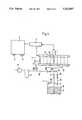
- FIG. 1is a schematic illustration of one exemplary embodiment of the inventive unit for filling electrochemical cells.
- FIG. 2is a block diagram illustrating the operational sequence pursuant to one prescribed cycle for controlling the filling unit of FIG. 1.
- the method of the present inventionis characterized primarily by the steps of: first evacuating the cells and simultaneously checking the same for short circuits, whereby for any cell determined to have a short circuit, the further filling process is terminated: and after the final vacuum level has been achieved in the cells, subsequently filling the same with the electrolyte while simultaneously monitoring the electrical voltage at the cells, whereby for any cell determined to have a deviation from a prescribed voltage range, the filling process is terminated.
- each of the cellsbe connected to a supply line, which is provided with a cell valve, not only for the evacuation but also for the filling with the electrolyte; if a short circuit or a deviation in voltage is encountered in a particular cell, the corresponding cell valve is closed.
- a cell valvenot only for the evacuation but also for the filling with the electrolyte; if a short circuit or a deviation in voltage is encountered in a particular cell, the corresponding cell valve is closed.
- the disruptionis preferably fed to a visual and/or audible indicator mechanism, with the latter being, for example, in the form of a horn or buzzer.
- a visual and/or audible indicator mechanismwith the latter being, for example, in the form of a horn or buzzer. The operating personnel can consequently immediately recognize that one of the cells is defective.
- a particular filling timeis preferably prescribed for filling the cells with the electrolyte.
- the unit for carrying out the method of the present inventionis characterized primarily by: a control mechanism for the unit; an electronic measuring mechanism connected to the control mechanism and to the cells for checking the cells for short circuits and for monitoring the voltage of the cells; an electrolyte tank for the electrolyte; a vacuum pump; first supply line means leading from the electrolyte tank to the cells; second supply line means leading from the vacuum pump to the cells; first valve means (a filling valve) disposed in the first supply line; and second valve means (a vacuum valve) disposed in the second supply line.
- This inventive unitrepresents a technically straightforward approach for being able to automatically carry out the inventive filling process.
- a condensate trapis disposed upstream of the vacuum pump.
- the supply lines that lead from the electrolyte tank and from the vacuum pumpopen out in a distributor, from where respective cell supply lines lead to the individual cells, with each of these cell supply lines having disposed therein a cell valve.
- These cell supply lines and the cell valveshave the advantage that by closing the cell valve of a defective cell, this cell can be disconnected from the further filling process without having to shut down the entire unit.
- FIG. 1serves for the filling of electrochemical cells 1, especially lithium cells, with an electrolyte 2.
- the cells 1are disposed next to one another in a distribution station 3; for the sake of simplicity, only a single cell 1 is illustrated in FIG. 1.
- a control mechanism (SPS) 4is provided that has appropriate inputs 5 and outputs 6.
- This control mechanism 4 for the unitis connected with an electronic measuring mechanism 7 that in turn is connected with the electrodes of the cells 1, so that it is possible therewith to undertake a check for short circuits as well as to monitor voltage during the filling process.
- the unitis furthermore provided with an electrolyte tank 8 for accommodating the electrolyte 2.
- This electrolyte tank 8is provided with vent means 9.
- a supply line 10leading from the electrolyte tank 8 is a supply line 10 in which is disposed a filling valve 11. Opening into the electrolyte tank is a discharge line 12 in which is disposed an appropriate discharge valve 13. This discharge line 12 starts from a junction 14 in the supply line 10.
- the unitis also provided with a vacuum pump 15 to evacuate the cells 1.
- the vacuum pump 15is connected to the junction 14 via a line 16; disposed ahead of the vacuum pump 15 are a condensate trap 17, vacuum switch means 18, and a valve 19.
- the distribution station 3 of the filling unitis provided with the electrochemical cells 1.
- the electrolyte supply openings in the cells 1are connected with the cell supply lines 22.
- the actual filling processcan then be started with a push button.
- the electrical linesare first automatically contacted; in other words, the terminals or end poles of the cells 1 are connected with the electronic measuring mechanism 7.
- the cells 1are thereupon evacuated by starting the vacuum pump 15 and opening the valve 19 as well as the cell valves 23.
- the physical basis for the filling operationis provided in that the cells 1, as a result of the partial vacuum, fill themselves with the electrolyte via suction.
- the rate of filling of the cells 1can be affected by the pressure differential between the cells and the electrolyte tank 8.
- the filling valve 11 and the discharge valve 13are closed during this procedure.
- This mechanism 7monitors whether the cells 1 are in order, i.e. whether or not there is a short circuit in the cells. If the cells 1 are in order, they are evacuated until the final vacuum is achieved.
- the vacuum valve 19is closed. Subsequently, by opening the filling valve 11 the process of filling the cells 1 with the electrolyte 2 is started, whereby simultaneous with the filling, the electrical voltage present at the cells 1 is monitored by the electronic measuring mechanism 7. As long as the voltage is in a prescribed theoretical range, the filling process is maintained until a prescribed filling time has expired, after which the cells 1 are completely filled.
- the processis immediately terminated by closing the corresponding cell valve 23 and is indicated by a disruption indication as well as by a horn or buzzer, so that subsequently an automatic removal of this defective cell 1 can be undertaken.
Landscapes
- Chemical & Material Sciences (AREA)
- Chemical Kinetics & Catalysis (AREA)
- Electrochemistry (AREA)
- General Chemical & Material Sciences (AREA)
- Filling, Topping-Up Batteries (AREA)
Abstract
Description
Claims (5)
Applications Claiming Priority (2)
| Application Number | Priority Date | Filing Date | Title |
|---|---|---|---|
| DE3912846ADE3912846C1 (en) | 1989-04-19 | 1989-04-19 | |
| DE3912846 | 1989-04-19 |
Publications (1)
| Publication Number | Publication Date |
|---|---|
| US5212867Atrue US5212867A (en) | 1993-05-25 |
Family
ID=6378994
Family Applications (1)
| Application Number | Title | Priority Date | Filing Date |
|---|---|---|---|
| US07/518,559Expired - Fee RelatedUS5212867A (en) | 1989-04-19 | 1989-12-01 | Method and unit for filling electrochemical cells |
Country Status (2)
| Country | Link |
|---|---|
| US (1) | US5212867A (en) |
| DE (2) | DE3912846C1 (en) |
Cited By (11)
| Publication number | Priority date | Publication date | Assignee | Title |
|---|---|---|---|---|
| US5588970A (en)* | 1994-07-06 | 1996-12-31 | Hughett; Elmer | Method for vacuum filling and sealing of a battery cell |
| US5601623A (en)* | 1995-08-03 | 1997-02-11 | Fauteux; Denis G. | Electrolytic cell and electrolytic process within a carbon dioxide environment |
| US5738690A (en)* | 1994-07-06 | 1998-04-14 | Hughett; Elmer | Method of filling battery cell |
| US6207318B1 (en) | 1998-06-22 | 2001-03-27 | Eagle-Picher Energy Products Corporation | Electrochemical batteries with restricted liquid electrolyte volume |
| US20030154593A1 (en)* | 2002-02-20 | 2003-08-21 | Varta Microbattery Gmbh, A Corporation Of Germany | Method for manufacturing galvanic elements |
| US6676714B2 (en)* | 2001-02-08 | 2004-01-13 | Eveready Battery Company, Inc. | Apparatus and method for assembling a flexible battery that is electrolyte-tight |
| US20040103526A1 (en)* | 2002-03-08 | 2004-06-03 | Werner Erhardt | Method and device for filling volatile liquids into the housing of electric components and for sealing the housing |
| US20130312869A1 (en)* | 2010-11-24 | 2013-11-28 | Li-Tec Battery Gmbh | Method and device for filling an electrochemical cell |
| CN112952305A (en)* | 2021-01-27 | 2021-06-11 | 东莞市创明电池技术有限公司 | Liquid injection equipment and method for battery cell |
| WO2022164033A1 (en)* | 2021-02-01 | 2022-08-04 | (주)에이프로 | Pressure activation device provided with short-circuiting inspection part for battery cell |
| US20240234992A9 (en)* | 2022-10-20 | 2024-07-11 | Samsung Sdi Co., Ltd. | Electrolyte injection device |
Families Citing this family (1)
| Publication number | Priority date | Publication date | Assignee | Title |
|---|---|---|---|---|
| DE29915950U1 (en) | 1999-09-10 | 1999-12-30 | CMW Automation GmbH, 65594 Runkel | Device for filling the cells of an accumulator with electrolyte |
Citations (6)
| Publication number | Priority date | Publication date | Assignee | Title |
|---|---|---|---|---|
| US3434887A (en)* | 1966-12-29 | 1969-03-25 | Harley Davidson Motor Co Inc | Battery fill apparatus |
| US3748186A (en)* | 1971-12-02 | 1973-07-24 | Power Conversion Inc | Method for filling sealed batteries |
| DE2541148A1 (en)* | 1975-09-16 | 1977-03-24 | Deutsche Automobilgesellsch | Battery filling unit for injecting electrolyte - has electronic circuit with probe monitoring level of liquid in cells |
| DE3439942A1 (en)* | 1983-11-03 | 1985-05-15 | VEB IFA-Automobilwerke Ludwigsfelde Stammbetrieb des IFA-Kombinates Nutzkraftwagen, DDR 1720 Ludwigsfelde | Device for the simultaneous metered filling of accumulators |
| US4529020A (en)* | 1980-01-29 | 1985-07-16 | General Electric Company | Method and apparatus for pressure filling an electrochemical cell |
| DE3744606A1 (en)* | 1987-12-31 | 1989-07-13 | Vni Pk I T Akkumuljatornyj I | Device for forming accumulators |
- 1989
- 1989-04-19DEDE3912846Apatent/DE3912846C1/denot_activeExpired - Lifetime
- 1989-04-19DEDE8916008Upatent/DE8916008U1/ennot_activeExpired - Lifetime
- 1989-12-01USUS07/518,559patent/US5212867A/ennot_activeExpired - Fee Related
Patent Citations (6)
| Publication number | Priority date | Publication date | Assignee | Title |
|---|---|---|---|---|
| US3434887A (en)* | 1966-12-29 | 1969-03-25 | Harley Davidson Motor Co Inc | Battery fill apparatus |
| US3748186A (en)* | 1971-12-02 | 1973-07-24 | Power Conversion Inc | Method for filling sealed batteries |
| DE2541148A1 (en)* | 1975-09-16 | 1977-03-24 | Deutsche Automobilgesellsch | Battery filling unit for injecting electrolyte - has electronic circuit with probe monitoring level of liquid in cells |
| US4529020A (en)* | 1980-01-29 | 1985-07-16 | General Electric Company | Method and apparatus for pressure filling an electrochemical cell |
| DE3439942A1 (en)* | 1983-11-03 | 1985-05-15 | VEB IFA-Automobilwerke Ludwigsfelde Stammbetrieb des IFA-Kombinates Nutzkraftwagen, DDR 1720 Ludwigsfelde | Device for the simultaneous metered filling of accumulators |
| DE3744606A1 (en)* | 1987-12-31 | 1989-07-13 | Vni Pk I T Akkumuljatornyj I | Device for forming accumulators |
Non-Patent Citations (15)
| Title |
|---|
| Bundesamt f r Wehrtechnik und Beschaffung; Presentation of test results; Sep. 20, 1988.* |
| Bundesamt f',uml/u/ r Wehrtechnik und Beschaffung; Presentation of test results; Sep. 20, 1988. |
| David Linden; Handbook of Batteries and Fuel Cells; "Reserve And Special Batteries" (date unknown). |
| David Linden; Handbook of Batteries and Fuel Cells; Reserve And Special Batteries (date unknown).* |
| Dr. G nter Eichinger and Dr. G nter Semrau; Studie ber Realisiebarkeitsnachweis Lithium Thionylchlorid Torpedobatterie F r Torpedo DM 2 A 4; Final Report of Jul. 1985 to Feb. 1988.* |
| Dr. Gunter Eichinger and Dr. Gunter Semrau; Studie uber Realisiebarkeitsnachweis Lithium-Thionylchlorid Torpedobatterie Fur Torpedo DM 2 A 4; Final Report of Jul. 1985 to Feb. 1988. |
| Notification of Presentation; Aug. 1986.* |
| Ralph E. White, J. O M. Bockris and B. E. Conway; Modern Aspects of Electrochemistry; pp. 215 216 (date unknown).* |
| Ralph E. White, J. O'M. Bockris and B. E. Conway; Modern Aspects of Electrochemistry; pp. 215-216 (date unknown). |
| Robert W. Brown; Lithium Thionyl Chloride Pressure Activated Reserve Battery (Parb); 11 14 Jun. 1984; pp. 460 465.* |
| Robert W. Brown; Lithium-Thionyl Chloride Pressure Activated Reserve Battery (Parb); 11-14 Jun. 1984; pp. 460-465. |
| Thomas M. Watson; Manufacturing Techniques for Hermetically Sealed Lithium Organic Electrolyte Cells; pp. 192 195 (date unknown).* |
| Thomas M. Watson; Manufacturing Techniques for Hermetically Sealed Lithiumrganic Electrolyte Cells; pp. 192-195 (date unknown). |
| U. Zak and G. Yariv; Lithium Thionyl Chloride, High Rate, Reserve Battery; pp. 453 459 (date unknown).* |
| U. Zak and G. Yariv; Lithium Thionyl Chloride, High-Rate, Reserve Battery; pp. 453-459 (date unknown). |
Cited By (16)
| Publication number | Priority date | Publication date | Assignee | Title |
|---|---|---|---|---|
| US5588970A (en)* | 1994-07-06 | 1996-12-31 | Hughett; Elmer | Method for vacuum filling and sealing of a battery cell |
| US5738690A (en)* | 1994-07-06 | 1998-04-14 | Hughett; Elmer | Method of filling battery cell |
| US5914201A (en)* | 1994-07-06 | 1999-06-22 | Hughett; Elmer | Filling fixture for electric vehicle cell |
| US5601623A (en)* | 1995-08-03 | 1997-02-11 | Fauteux; Denis G. | Electrolytic cell and electrolytic process within a carbon dioxide environment |
| US6207318B1 (en) | 1998-06-22 | 2001-03-27 | Eagle-Picher Energy Products Corporation | Electrochemical batteries with restricted liquid electrolyte volume |
| US6676714B2 (en)* | 2001-02-08 | 2004-01-13 | Eveready Battery Company, Inc. | Apparatus and method for assembling a flexible battery that is electrolyte-tight |
| US20030154593A1 (en)* | 2002-02-20 | 2003-08-21 | Varta Microbattery Gmbh, A Corporation Of Germany | Method for manufacturing galvanic elements |
| US7147675B2 (en)* | 2002-03-08 | 2006-12-12 | Epcos Ag | Method and device for filling volatile liquids into the housing of electric components and for sealing the housing |
| US20040103526A1 (en)* | 2002-03-08 | 2004-06-03 | Werner Erhardt | Method and device for filling volatile liquids into the housing of electric components and for sealing the housing |
| US20070074489A1 (en)* | 2002-03-08 | 2007-04-05 | Epcos Ag | Method for Introducing Volatile Liquids into the Housings of Electrical Components and for Closing the Housings |
| US20130312869A1 (en)* | 2010-11-24 | 2013-11-28 | Li-Tec Battery Gmbh | Method and device for filling an electrochemical cell |
| CN112952305A (en)* | 2021-01-27 | 2021-06-11 | 东莞市创明电池技术有限公司 | Liquid injection equipment and method for battery cell |
| CN112952305B (en)* | 2021-01-27 | 2022-07-15 | 东莞市创明电池技术有限公司 | Liquid injection equipment and method for battery cell |
| WO2022164033A1 (en)* | 2021-02-01 | 2022-08-04 | (주)에이프로 | Pressure activation device provided with short-circuiting inspection part for battery cell |
| US12399221B2 (en) | 2021-02-01 | 2025-08-26 | Apro Co., Ltd | Pressure activation apparatus provided with short-circuiting inspection section for battery cell |
| US20240234992A9 (en)* | 2022-10-20 | 2024-07-11 | Samsung Sdi Co., Ltd. | Electrolyte injection device |
Also Published As
| Publication number | Publication date |
|---|---|
| DE3912846C1 (en) | 1990-06-21 |
| DE8916008U1 (en) | 1992-10-15 |
Similar Documents
| Publication | Publication Date | Title |
|---|---|---|
| US5212867A (en) | Method and unit for filling electrochemical cells | |
| EP1130668B1 (en) | Battery sealing inspection method | |
| CN109386731B (en) | An SF6 gas automatic filling system and filling method for GIS equipment | |
| CN207881911U (en) | The air-tightness detection device of fuel battery pole board | |
| CN109823285A (en) | Electric vehicle high-voltage power-on and power-off system, power-on and power-off control method, and control system | |
| CA2199096A1 (en) | Process and apparatus for recovering components of sealed type battery | |
| CN207030939U (en) | A kind of supervising device of unloading for oil tank | |
| CN105953985A (en) | Lithium battery electrode cover plate helium mass spectrum leak detection method | |
| CN115371901A (en) | Control method for double-vacuum four-cavity air tightness detection machine of square-shell battery | |
| CN213900710U (en) | Gas discharging cabinet with hydrogen detection and analysis functions | |
| US4683745A (en) | Cannister seal integrity tester | |
| CN208637504U (en) | A kind of pail pack automatic vacuum displacement apparatus | |
| CN107293981A (en) | A kind of key power transmission and the handcart switch cabinet of key maintenance | |
| CN112648529A (en) | Automatic silane filling system and control method | |
| KR20160084110A (en) | System For Lithium-Ion Polymer Cell Degas And Manufacturing Method | |
| CN210272298U (en) | Air supply pipeline of vacuum chuck and laser annealing machine table | |
| JPH0845541A (en) | Sealing degree deciding method of sealed battery | |
| CN209673628U (en) | Wall-mount transformer oil dissolved gas on-Line Monitor Device based on laser detection | |
| CN211529920U (en) | Semiconductor equipment's cavity and semiconductor equipment | |
| CN210400757U (en) | Full-automatic sealing test and nitrogen filling integrated machine | |
| CN114517889A (en) | Control method for realizing online detection of hydrogen quality and hydrogenation system | |
| CN113203453A (en) | Quick calibration device and method for tuning fork switch | |
| CN119471413B (en) | Lithium-ion battery service status monitoring system based on artificial intelligence | |
| CN111946293A (en) | Intelligent alarm device for remote console of hydraulic blowout preventer | |
| KR101603748B1 (en) | Control apparatus for checking and changing insulating gas of load break switch on live wire state and method thereof |
Legal Events
| Date | Code | Title | Description |
|---|---|---|---|
| AS | Assignment | Owner name:ACCUMULATORENWERKE HOPPECKE CARL ZOELLNER & SOHN G Free format text:ASSIGNMENT OF ASSIGNORS INTEREST.;ASSIGNOR:VOGEL, KARL-WILHELM;REEL/FRAME:005295/0423 Effective date:19891106 | |
| AS | Assignment | Owner name:ULTRALIFE BATTERIES (UK) LTD.,, ENGLAND Free format text:ASSIGNMENT OF ASSIGNORS INTEREST;ASSIGNOR:ACCUMULATORENWERKE HOPPECKE CARL ZOELLNER & SOHN GMBH & CO. KG;REEL/FRAME:007226/0074 Effective date:19941014 | |
| REMI | Maintenance fee reminder mailed | ||
| LAPS | Lapse for failure to pay maintenance fees | ||
| FP | Lapsed due to failure to pay maintenance fee | Effective date:19970528 | |
| AS | Assignment | Owner name:CONGRESS FINANCIAL CORPORATION (NEW ENGLAND), MASS Free format text:SECURITY INTEREST;ASSIGNOR:ULTRALIFE BATTERIES, INC. A DELAWARE CORPORATION;REEL/FRAME:011149/0710 Effective date:20000615 | |
| AS | Assignment | Owner name:ULTRALIFE BATTERIES, INC., NEW YORK Free format text:RELEASE BY SECURED PARTY;ASSIGNOR:CONGRESS FINANCIAL CORPORATION;REEL/FRAME:015552/0206 Effective date:20040706 | |
| STCH | Information on status: patent discontinuation | Free format text:PATENT EXPIRED DUE TO NONPAYMENT OF MAINTENANCE FEES UNDER 37 CFR 1.362 |