US5212865A - Tool for installation of tanged and tangless wire inserts - Google Patents
Tool for installation of tanged and tangless wire insertsDownload PDFInfo
- Publication number
- US5212865A US5212865AUS07/915,207US91520792AUS5212865AUS 5212865 AUS5212865 AUS 5212865AUS 91520792 AUS91520792 AUS 91520792AUS 5212865 AUS5212865 AUS 5212865A
- Authority
- US
- United States
- Prior art keywords
- insert
- mandrel
- tangless
- tool
- tanged
- Prior art date
- Legal status (The legal status is an assumption and is not a legal conclusion. Google has not performed a legal analysis and makes no representation as to the accuracy of the status listed.)
- Expired - Lifetime
Links
Images


Classifications
- B—PERFORMING OPERATIONS; TRANSPORTING
- B25—HAND TOOLS; PORTABLE POWER-DRIVEN TOOLS; MANIPULATORS
- B25B—TOOLS OR BENCH DEVICES NOT OTHERWISE PROVIDED FOR, FOR FASTENING, CONNECTING, DISENGAGING OR HOLDING
- B25B27/00—Hand tools, specially adapted for fitting together or separating parts or objects whether or not involving some deformation, not otherwise provided for
- B25B27/14—Hand tools, specially adapted for fitting together or separating parts or objects whether or not involving some deformation, not otherwise provided for for assembling objects other than by press fit or detaching same
- B25B27/143—Hand tools, specially adapted for fitting together or separating parts or objects whether or not involving some deformation, not otherwise provided for for assembling objects other than by press fit or detaching same for installing wire thread inserts or tubular threaded inserts
- Y—GENERAL TAGGING OF NEW TECHNOLOGICAL DEVELOPMENTS; GENERAL TAGGING OF CROSS-SECTIONAL TECHNOLOGIES SPANNING OVER SEVERAL SECTIONS OF THE IPC; TECHNICAL SUBJECTS COVERED BY FORMER USPC CROSS-REFERENCE ART COLLECTIONS [XRACs] AND DIGESTS
- Y10—TECHNICAL SUBJECTS COVERED BY FORMER USPC
- Y10T—TECHNICAL SUBJECTS COVERED BY FORMER US CLASSIFICATION
- Y10T29/00—Metal working
- Y10T29/53—Means to assemble or disassemble
- Y10T29/53687—Means to assemble or disassemble by rotation of work part
- Y10T29/53691—Means to insert or remove helix
Definitions
- the present inventionprovides an improved installation tool which can install both tanged and tangless inserts in a pre-threaded hole.
- a prior art insertion tool for tangless wire coil insertsis described in Cosenza et al. U.S. Pat. No. 4,553,302.
- the toolincludes a moveable pawl that automatically locks into a cut out formed in the lead thread of the insert rotation of the tool (insert) positioning the insert into a pre-threaded hole, thus completing installation of the insert.
- the present inventionprovides a multi purpose tool for installing helical wire formed inserts of either the tanged or tangless type into a pre-threaded hole.
- the tool nosepasses freely through the internal diameter of the insert since there is no tang to stop the movement of a tool until a pawl positioned within the tool body automatically engages the cut out formed in the lead thread of the insert.
- the nose of the tooldoes not pass freely through the insert due to the presence of the tang that blocks its way.
- a ledge portion formed on the nose portion of the toolforces the insert to wind itself in the threads of the parent material.
- the pawl that is directly behind the nose of the toolremains ineffective in a retracted position since there is no cut out provided for the pawl in the insert.
- the present inventionthus provides a multi-purpose tool which can install either tangless or tang inserts into a pre-threaded hole in a parent material.
- the operatorthus does not need to separate inserts during the installation cycle and only requires a single tool to do installations of both, thus reducing capital and labor costs.
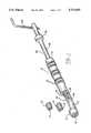
- FIG. 1is a perspective view of a multi purpose tool in accordance with the teachings of the present invention and also illustrating tangless and tanged helical coiled inserts;
- FIG. 2is a side elevation, partially broken away, of the tool of FIG. 1 with the pawl pivoted inwardly;
- FIG. 3is a side elevation of the tool, of the present invention showing the position of the pawl prior to the
- FIG. 4is a side elevation view of the tool of the present invention showing the position of the pawl prior to the installation of the tangless insert into a tapped hole;
- FIGS. 5A and 5Bare detail views of the nose tip of a mandrel assembly utilized in the present invention.
- the tool of the present inventionis adapted for use with both tanged and tangless coils which are used, for example, where a steel alloyed bolt having conventional threads is desired to be fastened into a material of relatively softer material, such as aluminum.
- the installation tool 10 of the present inventionis comprised of two major portions: a tubular body member 12, and a mandrel assembly 14 insertable into the tubular body and adapted to receive a tanged or tangless insert which is to be threaded into a tapped hole.
- the tubular body member 12provides, in part, the operator with a means for supporting the mandrel assembly 14 in order to install the insert correctly during operation.
- the tubular body member 12may include a loading window 16 for supporting an insert for quick reloading, a coil alignment portion 19, and a coil sizing portion, or prewinder, 18 which reduces the coil thread diameter for smooth transition into the tapped hole.
- the mandrel assembly 14is insertable into the tubular body member 12 and is adapted to receive the tangless or tanged insert 11 and 13, respectively, for installation into a tapped hole.
- the mandrel assembly 14comprises a cylindrical rod 20 of a diameter substantially equal to the inner diameter of the tubular body member 12.
- the lead end 22 of the rod 20is threaded and has a diameter according to the inner diameter that insert 11 (tangless) on 13 (tanged) will have when in its contracted state. This means the diameter of lead end 22 is somewhat smaller than the inner coil diameter of inserts 11 and 13 prior to the application of the tool.
- At the end opposite the lead end 22there is generally a crank handle 24 for applying torque for installing the insert into a tapped hole.
- the crank handle 24may be replaced at the driver end of the cylindrical rod 20 with a shaped portion, to which a wrench may be applied.
- an adjustable stop collar 26serves as an abutment with the end portion 9 of tubular body member 12, thereby limiting the distance that the lead end 22 of the rod 20 may project out of the coil sizing portion 18 of the tubular body member 12, thus defining the proper depth to which the inserts 11 or 13 may be installed in a tapped hole.
- a set screw 28 or other meansis provided in the adjustable stop collar 26 to secure the stop in its proper position.
- FIGS. 2 and 3illustrate a pivotable catch or pawl 30, constructed in accordance with one of the embodiments disclosed in U.S. Pat. No. 4,553,302, in an elevation sectional view within a longitudinal cutout 32 of mandrel assembly 14.
- the cutout 32generally does not extend through the front end 22 of the rod 20, but is generally equal in length to the pawl 30.
- the pawl 30is biased within the cutout 32 so that a hook portion 34 protrudes through aperture 33 and engages the recess 52 of the tangless wire coil insert 11 (FIG. 4).
- the pawl 30is generally biased about pivot point 36 by spring 38 to locate the hook portion 34 into the recess of the tangless insert when the tangless insert 11 is screwed onto the lead end 22 of the mandrel assembly 14 and the mandrel assembly 14 is axially moved in the tubular body 12 so that the cam means 48 moves from the smaller inner diameter portion 49 of tubular body 12 along ramp 50 to the larger inner diameter 51.
- a tanged insert 13is to be utilized pawl 30 remains in the inoperative position since there is no recess to receive hook portion 34.
- the front end 22 of rod 20is increased in length when compared to the length of the rod shown in U.S. Pat. No. 4,553,302 in order to form a ledge portion 60 on front end 21 or rod 20.
- Cutout 61 formed in ledge portion 60captures tang 15 of tanged insert 13 and applies a force thereto causing insert 13 to wind itself in the threads of parent material 17.
- the configuration of ledge portion 60is similar to those on tools currently utilized to install tanged inserts such as that shown in U.S. Pat. No. 3,348,293 or tools available from Camloc Products, Hasbrouck Heights, N.J., such as the Prewinder, Capture Sleeve Type, Style 2 model.
- the tool of the present inventionfunctions like the tool disclosed in U.S. Pat. No. 4,553,302. That is, the front end, or nose, 21 of the tool passes freely through the internal diameter of insert 11 (since there is no tang to stop it) until the pawl 30 automatically engages the appropriate cutout 52 of the tangless insert 11. As the tool continues to rotate within the internal diameter of insert 11, the insert is forced to wind itself in the threads of parent material 17 in a conventional manner. Once the proper depth of the insert 11 in the parent material 17 has been achieved, the tool stops rotating and is reversed for proper disengagement and installation is complete.
- next insert to be installedis a tanged version such as insert 13
- the operatorthen proceeds with the installation exactly the same as for the tangless version.
- the front end, or nose, 21 of the tooldoes not pass freely through the insert 13 due to the presence of the tang 15 that is blocking its way.
- the ledge 60 formed in nose portion 21captures tang 15 and forces the insert 13 to wind itself in the threads of the prewinder 18 and then the parent material 17 in a conventional manner.
- FIG. 4illustrates the installation of a tangless insert 11 into the threads of prewinder 18 with the nose portion 21 extending into tapped hole 8.
- the installation procedureis identical to that described in U.S. Pat. No. 4,553,302.
- FIG. 5Ashows in more detail the side view of nose portion 21 of mandrel 22 with ledge portion 60 and FIG. 5B is a front view of the detail shown in FIG. 5A.
- the present inventionthus provides a multi-purpose tool which can function easily with either a tanged or tangless insert.
- the operatordoes not need to separate the inserts during the installation cycle. Since the hole preparation is identical for both types of inserts, the operator simply uses this tool in the normal manner thus reducing both labor and capital costs.
Landscapes
- Engineering & Computer Science (AREA)
- Mechanical Engineering (AREA)
- Hand Tools For Fitting Together And Separating, Or Other Hand Tools (AREA)
Abstract
Description
Claims (4)
Priority Applications (7)
| Application Number | Priority Date | Filing Date | Title |
|---|---|---|---|
| US07/915,207US5212865A (en) | 1992-07-20 | 1992-07-20 | Tool for installation of tanged and tangless wire inserts |
| IL10490893AIL104908A (en) | 1992-07-20 | 1993-03-02 | Tool for inserting helically coiled wire inserts in a pre-threaded hole |
| AU35146/93AAU656459B2 (en) | 1992-07-20 | 1993-03-11 | Tools for installation of both tanged and tangless wire inserts |
| CA002091724ACA2091724C (en) | 1992-07-20 | 1993-03-16 | Tools for installation of both tnaged and tangless wire inserts |
| KR1019930004710AKR960008258B1 (en) | 1992-07-20 | 1993-03-25 | Tool for installation of both tanged and tangless wire insert |
| JP12462693AJP3500166B2 (en) | 1992-07-20 | 1993-04-30 | Installation tool for tongue and non-tang inserts |
| EP93630042AEP0580544A1 (en) | 1992-07-20 | 1993-06-03 | Tools for installation of both tanged and tangless wire inserts |
Applications Claiming Priority (1)
| Application Number | Priority Date | Filing Date | Title |
|---|---|---|---|
| US07/915,207US5212865A (en) | 1992-07-20 | 1992-07-20 | Tool for installation of tanged and tangless wire inserts |
Publications (1)
| Publication Number | Publication Date |
|---|---|
| US5212865Atrue US5212865A (en) | 1993-05-25 |
Family
ID=25435393
Family Applications (1)
| Application Number | Title | Priority Date | Filing Date |
|---|---|---|---|
| US07/915,207Expired - LifetimeUS5212865A (en) | 1992-07-20 | 1992-07-20 | Tool for installation of tanged and tangless wire inserts |
Country Status (7)
| Country | Link |
|---|---|
| US (1) | US5212865A (en) |
| EP (1) | EP0580544A1 (en) |
| JP (1) | JP3500166B2 (en) |
| KR (1) | KR960008258B1 (en) |
| AU (1) | AU656459B2 (en) |
| CA (1) | CA2091724C (en) |
| IL (1) | IL104908A (en) |
Cited By (25)
| Publication number | Priority date | Publication date | Assignee | Title |
|---|---|---|---|---|
| US5830221A (en)* | 1996-09-20 | 1998-11-03 | United States Surgical Corporation | Coil fastener applier |
| US6000114A (en)* | 1997-12-31 | 1999-12-14 | Emhart Inc. | Insertion tool |
| US6367138B1 (en)* | 1999-09-15 | 2002-04-09 | Emhart Inc. | Power installation tool for helical coil inserts |
| US20030009441A1 (en)* | 1996-09-20 | 2003-01-09 | Holsten Henry E. | Coil fastener applier and removal method |
| US6704985B1 (en) | 2003-01-16 | 2004-03-16 | James R. Marshall | Threaded tool insert |
| US20040187288A1 (en)* | 2003-02-13 | 2004-09-30 | Eduard Bruehwiler | Method of installing spiral threaded inserts and installation tool for carrying out the method |
| US20070245533A1 (en)* | 2006-04-19 | 2007-10-25 | Jan Szewc | Adjustable prewinder assembly for wire insert installation tool |
| US20080097523A1 (en)* | 1994-08-05 | 2008-04-24 | Lee Bolduc | Surgical helical fastener with applicator |
| US20090158568A1 (en)* | 2007-12-19 | 2009-06-25 | Yu Hsin Li | Installation tool for helical coil inserts |
| US20090158569A1 (en)* | 2006-06-06 | 2009-06-25 | Honda Motor Co., Ltd. | Installation tool and correction tool for helical coil insert |
| US20090293248A1 (en)* | 2008-06-03 | 2009-12-03 | Advanex Inc. | Tanged insert insertion tool |
| WO2008155766A3 (en)* | 2007-06-18 | 2010-02-25 | Meital (B.L.) Precision Machining Ltd. | Automatic installation system and method for threaded inserts |
| GB2491668A (en)* | 2011-06-10 | 2012-12-12 | Yu Hsin Li | Installation tool for helical threaded insert |
| US20120324689A1 (en)* | 2011-06-27 | 2012-12-27 | Yu Hsin Li | Installation tool for helical threaded insert |
| US8474118B2 (en) | 2010-07-30 | 2013-07-02 | Nippon Sprew Co., Ltd. | Insertion tool for tangless spiral coil insert |
| US8495807B2 (en) | 2009-06-25 | 2013-07-30 | Newfrey Llc | Retractable prewinder assembly with infinite adjustability for installation of helically coiled wire inserts |
| US9421676B2 (en) | 2012-05-29 | 2016-08-23 | Nippon Sprew Co., Ltd. | Extraction tool for tangless spiral coil insert |
| WO2017046213A1 (en)* | 2015-09-15 | 2017-03-23 | Fill Gesellschaft M.B.H. | Tool and method for mounting threaded inserts |
| US20170284444A1 (en)* | 2010-11-08 | 2017-10-05 | Böllhoff Verbindungstechnik GmbH | Wire thread insert with redressable mounting tang as well as its manufacturing and installation |
| US20170361440A1 (en)* | 2014-11-24 | 2017-12-21 | Böllhoff Verbindungstechnik GmbH | Installation tool for a wire thread insert having an installation pin that can be bent back, and installation method |
| US20180238591A1 (en)* | 2013-03-15 | 2018-08-23 | Thomas Scott Breidenbach | Screw-in geothermal heat exchanger systems and methods |
| CN110238790A (en)* | 2019-07-01 | 2019-09-17 | 国家电网有限公司 | Auxiliary fuse disassembly device and usage method |
| US11059152B2 (en)* | 2018-10-19 | 2021-07-13 | Pratt & Whitney Canada Corp. | Tool and method for removing helical insert tang |
| US20240035509A1 (en)* | 2017-11-23 | 2024-02-01 | Böllhoff Verbindungstechnik GmbH | Wire thread insert |
| US20250262695A1 (en)* | 2022-05-10 | 2025-08-21 | Howmet Aerospace Inc. | Tangless helically coiled insert installation system |
Families Citing this family (7)
| Publication number | Priority date | Publication date | Assignee | Title |
|---|---|---|---|---|
| US6704984B2 (en)* | 2001-07-31 | 2004-03-16 | Newfrey Lcc | Prewinder apparatus for installation tools |
| KR20040079043A (en)* | 2003-03-06 | 2004-09-14 | 엘지이노텍 주식회사 | Inserting device for heli coil |
| USD561542S1 (en)* | 2004-08-19 | 2008-02-12 | Haas William C | Tool for wire installation |
| JP5639443B2 (en)* | 2010-11-08 | 2014-12-10 | 株式会社アキュレイト | Tool for tongueless coil thread |
| CN105071178B (en)* | 2015-08-12 | 2017-05-31 | 国家电网公司 | Change the device of electric energy meter intelligent checking table epitope binding post |
| KR20200002550U (en) | 2019-05-16 | 2020-11-25 | 이재익 | Heli coil having clamping force improved |
| CN113910164B (en)* | 2021-09-28 | 2023-02-17 | 中国石油化工股份有限公司 | Deep channel internal buckle screwing tool |
Citations (5)
| Publication number | Priority date | Publication date | Assignee | Title |
|---|---|---|---|---|
| US3093895A (en)* | 1963-06-18 | Wire coil installing tool | ||
| US3348293A (en)* | 1966-05-12 | 1967-10-24 | Heli Coil Corp | Wire coil installing tool |
| US4077101A (en)* | 1976-06-03 | 1978-03-07 | Wallace Robert P | Driver for helical thread inserts |
| US4227290A (en)* | 1979-05-07 | 1980-10-14 | Wallace Robert P | Drive mandrel for helical thread inserts |
| US4553302A (en)* | 1984-02-21 | 1985-11-19 | Rexnord Inc. | Installation tool, tangless helically coiled insert |
- 1992
- 1992-07-20USUS07/915,207patent/US5212865A/ennot_activeExpired - Lifetime
- 1993
- 1993-03-02ILIL10490893Apatent/IL104908A/ennot_activeIP Right Cessation
- 1993-03-11AUAU35146/93Apatent/AU656459B2/ennot_activeExpired
- 1993-03-16CACA002091724Apatent/CA2091724C/ennot_activeExpired - Lifetime
- 1993-03-25KRKR1019930004710Apatent/KR960008258B1/ennot_activeExpired - Lifetime
- 1993-04-30JPJP12462693Apatent/JP3500166B2/ennot_activeExpired - Lifetime
- 1993-06-03EPEP93630042Apatent/EP0580544A1/ennot_activeWithdrawn
Patent Citations (5)
| Publication number | Priority date | Publication date | Assignee | Title |
|---|---|---|---|---|
| US3093895A (en)* | 1963-06-18 | Wire coil installing tool | ||
| US3348293A (en)* | 1966-05-12 | 1967-10-24 | Heli Coil Corp | Wire coil installing tool |
| US4077101A (en)* | 1976-06-03 | 1978-03-07 | Wallace Robert P | Driver for helical thread inserts |
| US4227290A (en)* | 1979-05-07 | 1980-10-14 | Wallace Robert P | Drive mandrel for helical thread inserts |
| US4553302A (en)* | 1984-02-21 | 1985-11-19 | Rexnord Inc. | Installation tool, tangless helically coiled insert |
Cited By (39)
| Publication number | Priority date | Publication date | Assignee | Title |
|---|---|---|---|---|
| US20080097523A1 (en)* | 1994-08-05 | 2008-04-24 | Lee Bolduc | Surgical helical fastener with applicator |
| US20030009441A1 (en)* | 1996-09-20 | 2003-01-09 | Holsten Henry E. | Coil fastener applier and removal method |
| US5830221A (en)* | 1996-09-20 | 1998-11-03 | United States Surgical Corporation | Coil fastener applier |
| US6000114A (en)* | 1997-12-31 | 1999-12-14 | Emhart Inc. | Insertion tool |
| US6367138B1 (en)* | 1999-09-15 | 2002-04-09 | Emhart Inc. | Power installation tool for helical coil inserts |
| US6470557B2 (en) | 1999-09-15 | 2002-10-29 | Emhart Llc | Power installation tool for helical coil inserts |
| US6704985B1 (en) | 2003-01-16 | 2004-03-16 | James R. Marshall | Threaded tool insert |
| US20040187288A1 (en)* | 2003-02-13 | 2004-09-30 | Eduard Bruehwiler | Method of installing spiral threaded inserts and installation tool for carrying out the method |
| US7340814B2 (en)* | 2003-02-13 | 2008-03-11 | Alstom Technology Ltd. | Method of installing spiral threaded inserts and installation tool |
| US7634844B2 (en) | 2006-04-19 | 2009-12-22 | Newfrey Llc | Adjustable prewinder assembly for wire insert installation tool |
| US20070245533A1 (en)* | 2006-04-19 | 2007-10-25 | Jan Szewc | Adjustable prewinder assembly for wire insert installation tool |
| US20090158569A1 (en)* | 2006-06-06 | 2009-06-25 | Honda Motor Co., Ltd. | Installation tool and correction tool for helical coil insert |
| WO2008155766A3 (en)* | 2007-06-18 | 2010-02-25 | Meital (B.L.) Precision Machining Ltd. | Automatic installation system and method for threaded inserts |
| US7587799B2 (en)* | 2007-12-19 | 2009-09-15 | Yu Hsin Li | Installation tool for helical coil inserts |
| US20090158568A1 (en)* | 2007-12-19 | 2009-06-25 | Yu Hsin Li | Installation tool for helical coil inserts |
| EP2130650A1 (en)* | 2008-06-03 | 2009-12-09 | Advanex Inc. | Tanged insert insertion tool |
| US20090293248A1 (en)* | 2008-06-03 | 2009-12-03 | Advanex Inc. | Tanged insert insertion tool |
| US8495807B2 (en) | 2009-06-25 | 2013-07-30 | Newfrey Llc | Retractable prewinder assembly with infinite adjustability for installation of helically coiled wire inserts |
| US8474118B2 (en) | 2010-07-30 | 2013-07-02 | Nippon Sprew Co., Ltd. | Insertion tool for tangless spiral coil insert |
| US20170284444A1 (en)* | 2010-11-08 | 2017-10-05 | Böllhoff Verbindungstechnik GmbH | Wire thread insert with redressable mounting tang as well as its manufacturing and installation |
| US10883527B2 (en) | 2010-11-08 | 2021-01-05 | Böllhoff Verbindungstechnik GmbH | Wire thread insert with redressable mounting tang as well as its manufacturing and installation |
| US10774868B2 (en)* | 2010-11-08 | 2020-09-15 | Böllhoff Verbindungstechnik GmbH | Wire thread insert with redressable mounting tang as well as its manufacturing and installation |
| US10704589B2 (en) | 2010-11-08 | 2020-07-07 | Böllhoff Verbindungstechnik GmbH | Wire thread insert with redress mounting tang as well as its manufacturing and installation |
| GB2491668A (en)* | 2011-06-10 | 2012-12-12 | Yu Hsin Li | Installation tool for helical threaded insert |
| US20120324689A1 (en)* | 2011-06-27 | 2012-12-27 | Yu Hsin Li | Installation tool for helical threaded insert |
| US9550287B2 (en)* | 2011-06-27 | 2017-01-24 | Yu-Hsin Li | Tool for installation of helical threaded insert |
| US20150047163A1 (en)* | 2011-06-27 | 2015-02-19 | Yu-Hsin Lin | Tool for installation of helical threaded insert |
| US9421676B2 (en) | 2012-05-29 | 2016-08-23 | Nippon Sprew Co., Ltd. | Extraction tool for tangless spiral coil insert |
| US11892201B2 (en)* | 2013-03-15 | 2024-02-06 | Thomas Scott Breidenbach | Installation apparatus/tool for tubular geothermal heat exchanger systems and methods |
| US20180238591A1 (en)* | 2013-03-15 | 2018-08-23 | Thomas Scott Breidenbach | Screw-in geothermal heat exchanger systems and methods |
| US20170361440A1 (en)* | 2014-11-24 | 2017-12-21 | Böllhoff Verbindungstechnik GmbH | Installation tool for a wire thread insert having an installation pin that can be bent back, and installation method |
| US10773365B2 (en)* | 2014-11-24 | 2020-09-15 | Böllhoff Verbindungstechnik GmbH | Installation tool for a wire thread insert having an installation pin that can be bent back, and installation method |
| DE112016004182B4 (en)* | 2015-09-15 | 2021-01-21 | Fill Gesellschaft M.B.H. | Procedure for assembling threaded inserts |
| WO2017046213A1 (en)* | 2015-09-15 | 2017-03-23 | Fill Gesellschaft M.B.H. | Tool and method for mounting threaded inserts |
| US12173743B2 (en)* | 2017-11-23 | 2024-12-24 | Böllhoff Verbindungstechnik GmbH | Wire thread insert |
| US20240035509A1 (en)* | 2017-11-23 | 2024-02-01 | Böllhoff Verbindungstechnik GmbH | Wire thread insert |
| US11059152B2 (en)* | 2018-10-19 | 2021-07-13 | Pratt & Whitney Canada Corp. | Tool and method for removing helical insert tang |
| CN110238790A (en)* | 2019-07-01 | 2019-09-17 | 国家电网有限公司 | Auxiliary fuse disassembly device and usage method |
| US20250262695A1 (en)* | 2022-05-10 | 2025-08-21 | Howmet Aerospace Inc. | Tangless helically coiled insert installation system |
Also Published As
| Publication number | Publication date |
|---|---|
| KR960008258B1 (en) | 1996-06-21 |
| AU3514693A (en) | 1994-01-27 |
| KR940002009A (en) | 1994-02-16 |
| IL104908A0 (en) | 1993-07-08 |
| JP3500166B2 (en) | 2004-02-23 |
| EP0580544A1 (en) | 1994-01-26 |
| CA2091724A1 (en) | 1994-01-21 |
| IL104908A (en) | 1996-08-04 |
| JPH06134679A (en) | 1994-05-17 |
| AU656459B2 (en) | 1995-02-02 |
| CA2091724C (en) | 2002-03-05 |
Similar Documents
| Publication | Publication Date | Title |
|---|---|---|
| US5212865A (en) | Tool for installation of tanged and tangless wire inserts | |
| US4553302A (en) | Installation tool, tangless helically coiled insert | |
| CA1232715A (en) | Removal tool for tangless helically coiled insert | |
| US5456145A (en) | Installation tool for tangless helically coiled insert | |
| CA1232714A (en) | Adapter for power tool installation of tangless helically coiled insert | |
| US6601480B1 (en) | Autofeed screwdriver for screws with flat head bottoms | |
| KR100200383B1 (en) | Installation tool for helical coil inserts | |
| US6089132A (en) | Screwdriver with dual cam slot for collated screws | |
| US5927163A (en) | Screwdriver with slotted nose for collated screws | |
| US4768270A (en) | Installation tool for helical coil inserts | |
| CA2110588C (en) | Compressible screw-type locking mechanism | |
| US4402203A (en) | Fastener installation tool | |
| US6321433B1 (en) | Double bevel prewinder mandrel | |
| GB2150476A (en) | Inserting threaded inserts |
Legal Events
| Date | Code | Title | Description |
|---|---|---|---|
| AS | Assignment | Owner name:VSI CORPORATION A DE CORP., VIRGINIA Free format text:ASSIGNMENT OF ASSIGNORS INTEREST.;ASSIGNOR:DAVIS, RICHARD L.;REEL/FRAME:006189/0408 Effective date:19920702 Owner name:VSI CORPORATION A DE CORP., VIRGINIA Free format text:ASSIGNMENT OF ASSIGNORS INTEREST.;ASSIGNOR:COSENZA, FRANK J.;REEL/FRAME:006189/0410 Effective date:19920707 | |
| STCF | Information on status: patent grant | Free format text:PATENTED CASE | |
| AS | Assignment | Owner name:KATO SPRING WORKS COMPANY, LTD., JAPAN Free format text:ASSIGNMENT OF ASSIGNORS INTEREST;ASSIGNOR:VSI CORPORATION;REEL/FRAME:006790/0196 Effective date:19930922 | |
| CC | Certificate of correction | ||
| FEPP | Fee payment procedure | Free format text:PAYOR NUMBER ASSIGNED (ORIGINAL EVENT CODE: ASPN); ENTITY STATUS OF PATENT OWNER: LARGE ENTITY | |
| FPAY | Fee payment | Year of fee payment:4 | |
| AS | Assignment | Owner name:CITICORP USA, INC., NEW YORK Free format text:SECURITY AGREEMENT;ASSIGNOR:FAIRCHILD HOLDING CORP.;REEL/FRAME:009958/0047 Effective date:19990420 | |
| AS | Assignment | Owner name:CITICORP USA, INC., NEW YORK Free format text:SECURITY INTEREST;ASSIGNOR:FAIRCHILD HOLDING CORP.;REEL/FRAME:010197/0395 Effective date:19990420 | |
| FPAY | Fee payment | Year of fee payment:8 | |
| AS | Assignment | Owner name:FAIRCHILD HOLDING CORP., VIRGINIA Free format text:RELEASE AND REASSIGNMENT OF PATENTS AND PATENT APPLICATIONS AS SECURITY;ASSIGNOR:CITICORP USA, INC.;REEL/FRAME:013552/0071 Effective date:20021203 | |
| AS | Assignment | Owner name:FAIRCHILD HOLDING CORP., VIRGINIA Free format text:RELEASE AND REASSIGNMENT OF PATENS AND PATENT APPLICATIONS AS SECURITY;ASSIGNOR:CITICORP USA, INC.;REEL/FRAME:013578/0655 Effective date:20021203 | |
| FPAY | Fee payment | Year of fee payment:12 |