US5211280A - Adjustable guide rail apparatus for independently adjusting positions of first and second guide rails disposed respectively on opposite sides of the path of a conveyor - Google Patents
Adjustable guide rail apparatus for independently adjusting positions of first and second guide rails disposed respectively on opposite sides of the path of a conveyorDownload PDFInfo
- Publication number
- US5211280A US5211280AUS07/850,529US85052992AUS5211280AUS 5211280 AUS5211280 AUS 5211280AUS 85052992 AUS85052992 AUS 85052992AUS 5211280 AUS5211280 AUS 5211280A
- Authority
- US
- United States
- Prior art keywords
- members
- bodies
- along
- channel
- guide rail
- Prior art date
- Legal status (The legal status is an assumption and is not a legal conclusion. Google has not performed a legal analysis and makes no representation as to the accuracy of the status listed.)
- Expired - Fee Related
Links
Images

Classifications
- B—PERFORMING OPERATIONS; TRANSPORTING
- B65—CONVEYING; PACKING; STORING; HANDLING THIN OR FILAMENTARY MATERIAL
- B65G—TRANSPORT OR STORAGE DEVICES, e.g. CONVEYORS FOR LOADING OR TIPPING, SHOP CONVEYOR SYSTEMS OR PNEUMATIC TUBE CONVEYORS
- B65G21/00—Supporting or protective framework or housings for endless load-carriers or traction elements of belt or chain conveyors
- B65G21/20—Means incorporated in, or attached to, framework or housings for guiding load-carriers, traction elements or loads supported on moving surfaces
- B65G21/2045—Mechanical means for guiding or retaining the load on the load-carrying surface
- B65G21/2063—Mechanical means for guiding or retaining the load on the load-carrying surface comprising elements not movable in the direction of load-transport
- B65G21/2072—Laterial guidance means
Definitions
- the present inventionrelates to an adjustable guide rail apparatus for adjusting positions of first and second guide rails disposed respectively on opposite sides of the path of a conveyor, for guiding articlesa along the path.
- Worm gearsare keyed on the lower end of the vertical shaft.
- a transversally disposed shafthas worm portions thereon for engaging the worm gears so that they will be rotated simultaneously.
- Meansare also provided on each end of the transversally disposed shaft for rotating it.
- an adjustable guide rail apparatusfor independently adjusting positions of first and second guide rails disposed respectively on opposite sides of a path of a conveyor, for guiding articles along said path, comprising:
- first and second elongated membersto be disposed respectively in parallel and along outward surfaces of said first and second guide rails, each of said members being provided with threaded sections along its length, said members being provided respectively with first and second handles at one of their extremities so that said members can be rotated by a user;
- each of said support meansincluding several bodies, each of said bodies having a first channel providing a passage to and supporting the corresponding elongated member along its length in such a way that said member can be rotated, and fixing means for fixing each of said bodies onto said conveyor so that said members can be fixed with respect to said conveyor, each of said support means having certain of their bodies provided with a second channel that is transversal and adjacent to the corresponding first channel, said certain bodies being located at threaded sections of said members;
- first and second locking meansoperatively associated with said first and second members respectively for preventing rotation thereof, each of said locking means being provided with a handle so that said members can be locked in desired positions by said user;
- each of said rodshaving an end that can be fixed onto the corresponding guide rail, and a threaded portion along its length, said rods being inserted into the corresponding second channel so that each of said rods can slide along the corresponding second channel and so that its threaded portion can be engaged with the threaded section of the corresponding elongated member; whereby said user can independently adjust said first and second guide rails by rotating said handles of said first and second elongated members, and lock said guide rails in desired positions by means of said handles of said first and second locking means.
- FIG. 1is a top view of a conveyor equipped with an adjustable guide rail apparatus in compliance with the present invention
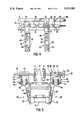
- FIG. 2is a cross-sectional view along line A--A of FIG. 1;
- FIG. 3is a cross-sectional view along line B--B of FIG. 1;
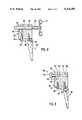
- FIG. 4is a side view along line C--C of FIG. 1;
- FIG. 5is a cross-sectional view along line D--D of FIG. 1.
- FIGS. 1, 2 and 3there is shown the adjustable guide rail apparatus for independently adjusting positions of first and second guide rails 2 and 4 disposed respectively on opposite sides of the path 6 of a conveyor 8, for guiding articles (not shown in these figures) along the path 6.
- the apparatuscomprises first and second elongated members 10 and 12 to be disposed respectively in parallel and along outward surfaces of the first and second guide rails 2 and 4.
- Each of the members 10 and 12is provided with threaded portions 13 along its length.
- the members 10 and 12are provided respectively with first and second handles 14 and 16 at one of their extremities so that they can be rotated by a user.
- first and second support devicesfor supporting respectively the members 10 and 12 in parallel and along the outward surfaces.
- Each of these support devicesincludes several bodies 18 and 20.
- Each of the bodies 18 and 20has a first channel 22 providing a passage to and supporting the corresponding elongated member 10 or 12 along its length in such a way that the member 10 or 12 can be rotated.
- Each of the bodies 18 and 20is provided with a L-shaped member 24 for fixing it onto the conveyor 8 so that the members 10 and 12 can be fixed with respect to the conveyor 8.
- Each of the support deviceshas certain bodies 20 provided with a second channel 26 that is transversal and adjacent to the corresponding first channel 22. These bodies 20 are located at threaded sections 13 of the members 10 and 12.
- first and second locking devices 28operatively associated with the first and second members 10 and 12 respectively for preventing rotation thereof.
- Each of the locking devices 28is provided with a handle 30 so that the members 10 and 12 can be locked in desired positions by the user.
- Rods 32 respectively associated with the bodies 20are provided. Each of these rods 32 has an end that can be fixed onto the corresponding guide rail 2 or 4, and a threaded portion along its length. The rods 32 are inserted into the corresponding second channel 26 so that each of these rods 32 can slide along the corresponding second channel 26 and so that its threaded portion can be engaged with the threaded section of the corresponding elongated member as it can be seen in FIG. 2.
- the usercan independently adjust the first and second guide rails 2 and 4 by rotating the handles 14 and 16 of the first and second elongated members 10 and 12, and lock the guide rails 2 and 4 in desired positions by means of the handles 30 of the first and second locking devices 28.
- Each of the elongated members 10 and 12comprises mechanical joints 36 and 38 connecting together each of the threaded portions 13. These mechanical joints 36 and 38 comprises pivotal mechanical joints 38 so that each of the elongated members 10 and 12 can follow a curve along the path 6 as shown in FIG. 1.
- Each of the L-shaped members 24has an upper horizontal section 41 that can be fixed onto the corresponding body 18 or 20 by means of screws 40, and a lateral vertical section that can be fixed onto lateral portions of the conveyor 8 by means of screws.
- Each of the L-shaped members 24has its horizontal section provided with a slot 43 adapted to receive the screws 40 so that each body 20 can be adjusted with respect to the conveyor 8 in a horizontal manner.
- Each of the support deviceshas a predetermined one of its bodies 18 and 20 that is a right parallelepiped having a first side 42 provided with a longitudinal slot 44 that follows and reaches the corresponding first channel 22, and a second side 46 provided with a cylindrical cavity 48 transversal to the corresponding slot 44.
- the cavity 48has a portion that goes beyond the slot 44 and that is provided with threads.
- Each of the locking devices 28comprises a rod 50 having an end connected to its handle 30 and an opposite end provided with threads capable of cooperating with the threads of the corresponding cavity 48.
- Each handle 30 of the locking devices 28comprises a stop 52 that can rest against the second side 46 of the parallelepiped when its rod 50 is screwed into the cavity 48. Then, the user can lock each of the elongated members 10 and 12 in the desired positions, by screwing the locking devices 28 into the cavities 48 to squeeze and lock the elongated members 10 and 12 in their corresponding channels 22.
- the handles 14 and 16 of the elongated members 10 and 12are adjacent.
- the locking devices 28are adjacent to the handles 14 and 16 so that the user can efficiently adjust the guide rails 2 and 4 and lock the apparatus in desired positions, at one location.
- FIG. 4there is shown a side view along line C--C of FIG. 1.
- a connecting assembly 60for connecting a straight section of the conveyor 8 to a curved section.
- This connecting assembly 60comprises a plate 62 that is connected onto the straight section of the conveyor by means of a screw 64.
- This connecting assembly 60also comprises a transversal plate 66 that is solid with the plate 62, and that has an extremity adapted to fit with the curved section of the conveyor.
- the L-shaped members 24are provided with vertical slots 68 adapted to receive screws 70 that connect the members 24 onto the conveyor.
- the slots 68provide a means for adjusting the L-shaped members 24 with respect to the conveyor in a vertical manner.
- FIG. 5there is shown a cross-sectional view along line D--D of FIG. 1.
- the article 76is positioned with respect to the guide rails 2 and 4.
- the bodies 18 and 20are fixed with respect to the conveyor 8.
Landscapes
- Engineering & Computer Science (AREA)
- Mechanical Engineering (AREA)
- Framework For Endless Conveyors (AREA)
Abstract
Description
Claims (6)
Priority Applications (2)
| Application Number | Priority Date | Filing Date | Title |
|---|---|---|---|
| US07/850,529US5211280A (en) | 1992-03-13 | 1992-03-13 | Adjustable guide rail apparatus for independently adjusting positions of first and second guide rails disposed respectively on opposite sides of the path of a conveyor |
| CA002090824ACA2090824A1 (en) | 1992-03-13 | 1993-03-02 | Adjustable guide rail apparatus for independently adjusting positions of first and second guide rails disposed respectively on opposite sides of the path of a conveyor |
Applications Claiming Priority (1)
| Application Number | Priority Date | Filing Date | Title |
|---|---|---|---|
| US07/850,529US5211280A (en) | 1992-03-13 | 1992-03-13 | Adjustable guide rail apparatus for independently adjusting positions of first and second guide rails disposed respectively on opposite sides of the path of a conveyor |
Publications (1)
| Publication Number | Publication Date |
|---|---|
| US5211280Atrue US5211280A (en) | 1993-05-18 |
Family
ID=25308389
Family Applications (1)
| Application Number | Title | Priority Date | Filing Date |
|---|---|---|---|
| US07/850,529Expired - Fee RelatedUS5211280A (en) | 1992-03-13 | 1992-03-13 | Adjustable guide rail apparatus for independently adjusting positions of first and second guide rails disposed respectively on opposite sides of the path of a conveyor |
Country Status (2)
| Country | Link |
|---|---|
| US (1) | US5211280A (en) |
| CA (1) | CA2090824A1 (en) |
Cited By (57)
| Publication number | Priority date | Publication date | Assignee | Title |
|---|---|---|---|---|
| US5291988A (en)* | 1993-08-23 | 1994-03-08 | Leonard George E | Adjustable guide rail apparatus for conveyor systems |
| US5386900A (en)* | 1993-08-25 | 1995-02-07 | Aluminum Company Of America | Adjustable infeed design |
| US5517798A (en)* | 1994-11-07 | 1996-05-21 | The Paxall Group, Inc. | Carton conveyor and loading apparatus |
| FR2758131A1 (en)* | 1997-01-06 | 1998-07-10 | Gebo Production | Spacing guide for conveyed containers |
| CH689670A5 (en)* | 1995-03-21 | 1999-08-13 | Rotzinger Ag | Transfer conveyor with a lateral dropping of Stueckguetern preventing side guide. |
| WO2000017073A1 (en)* | 1998-09-22 | 2000-03-30 | Moore Leslie A | Adjustable guide rail for transporting products |
| US6059096A (en)* | 1997-06-25 | 2000-05-09 | Dillin Engineered Systems Corporation | Guide system for packages on a curved conveyor |
| US6105757A (en)* | 1995-10-06 | 2000-08-22 | Valu Engineering, Inc. | Rail and bed system |
| US6269751B1 (en)* | 1997-05-02 | 2001-08-07 | Koenig & Bauer Aktiengesellschaft | Length-variable sliding rail element for a roller chain |
| US6305528B1 (en) | 2000-01-26 | 2001-10-23 | Flow Engineering | Apparatus and method for adjusting the position of guide rails in conveyors |
| US6318935B1 (en)* | 1998-11-23 | 2001-11-20 | Ouellette Machinery Systems, Inc. | Braking system for air conveyors |
| US6378695B1 (en) | 2000-09-15 | 2002-04-30 | Rhett L. Rinne | Conveyor apparatus with adjustable guide rails |
| US6454084B2 (en)* | 2000-01-21 | 2002-09-24 | Tetra Laval Holdings & Finance S.A. | Support railing for a curved conveyor path |
| US6478514B1 (en)* | 1999-01-12 | 2002-11-12 | Oullette Machinery Systems, Inc. | Neck ring guide change-over for an air conveyor |
| WO2004074142A1 (en)* | 2003-02-18 | 2004-09-02 | Sidel (Canada) Inc. | Adjustable curved guideway for a conveyor and method for realising same |
| WO2004099042A1 (en)* | 2003-05-09 | 2004-11-18 | Krones Ag | Conveyor line comprising an adjustable railing and actuating drive |
| US20060096843A1 (en)* | 2004-11-08 | 2006-05-11 | Hosch Michael A | Washdown conveyor corner section with removable wear strips |
| US20060163043A1 (en)* | 2003-02-18 | 2006-07-27 | Sidel (Canada) Inc. | Actuating assembly for an adjustable width guideway in a conveyor system for bottles |
| US20080099311A1 (en)* | 2006-10-27 | 2008-05-01 | Hartness International, Inc. | Adjustable side rails for article conveying system, and conveyor and system incorporating same |
| US20080156621A1 (en)* | 2004-06-01 | 2008-07-03 | Hakon Lundberg | Arrangement And Method For Adjustment Of Rail At A Conveyor |
| US20090108043A1 (en)* | 2005-09-21 | 2009-04-30 | Peter Franz Beck | Device and Method for Feeding at Least One Material Web or Web Strand into a Folding Device |
| WO2009109802A1 (en)* | 2008-03-03 | 2009-09-11 | Sidel Participations | Container transfer device including an adjustable peripheral guide |
| US20100200373A1 (en)* | 2004-09-01 | 2010-08-12 | Mcalister Mark | Adjustable conveyor guide |
| WO2010142919A1 (en) | 2009-06-11 | 2010-12-16 | Sidel Participations | Width-adjusting device for conveyor corridor(s) |
| US20110079493A1 (en)* | 2009-10-02 | 2011-04-07 | Bell Glen A | Guide rail system |
| US20110088997A1 (en)* | 2008-06-13 | 2011-04-21 | Sidel Participations | Multipath conveyor installation |
| US20110120120A1 (en)* | 2009-11-20 | 2011-05-26 | Advanced Manufacturing Technology for Bottles, Inc . | Novel Positioner Apparatus and Methods |
| US20110186144A1 (en)* | 2010-01-29 | 2011-08-04 | Advanced Manufacturing Technology For Bottles, Inc. | Pressurized Fluid Positioner Control System |
| US20110203907A1 (en)* | 2009-02-10 | 2011-08-25 | Khs Gmbh | Adjusting device for use on a conveyor |
| US8025141B1 (en)* | 2008-12-23 | 2011-09-27 | Bouldin Corporation | Contour trimmer for potted plants |
| US8186503B1 (en) | 2010-09-23 | 2012-05-29 | SEETECH Systems, Inc. | Adjustable curved fence assembly |
| US20120168283A1 (en)* | 2008-05-20 | 2012-07-05 | Flexibility Engineering, Llc | Position Control Apparatus and Methods |
| US8464864B2 (en) | 2010-10-29 | 2013-06-18 | Septimatech Group Inc. | Guide rail system |
| US8695787B2 (en) | 2011-09-26 | 2014-04-15 | Septimatech Group Inc. | Guide rail system |
| EP2821353A1 (en) | 2013-07-04 | 2015-01-07 | Krones Aktiengesellschaft | Conveyor section of a horizontal conveyor with at least one adjustable guide element |
| ITBO20130620A1 (en)* | 2013-11-12 | 2015-05-13 | Bett Sistemi Srl | APPARATUS FOR PRODUCT CONVEYANCE. |
| US9133865B2 (en) | 2008-05-20 | 2015-09-15 | Flexibility Engineering, Llc | Position control apparatus |
| US20150257398A1 (en)* | 2012-08-29 | 2015-09-17 | Nordischer Maschinenbau Rud. Baader Gmbh + Co. Kg | Conveying device for items in the fish and meat processing industry |
| US20160052720A1 (en)* | 2008-05-20 | 2016-02-25 | Flexibility Engineering, Llc | Flow Restricted Positioner Control Apparatus and Methods |
| US20160122132A1 (en)* | 2014-10-29 | 2016-05-05 | Septimatech Group Inc. | Lane adjustment system |
| US20160300737A1 (en)* | 2015-04-07 | 2016-10-13 | Boe Technology Group Co., Ltd. | Airflow Control Device and Method of Adjusting the Same, Substrate Cleaning Device |
| US9481524B2 (en) | 2014-02-21 | 2016-11-01 | Septimatech Group Inc. | Guide rail system with cover element |
| US9677576B2 (en) | 2015-09-14 | 2017-06-13 | Flexbility Engineering, LLC | Flow restricted positioner control apparatus and methods |
| US9828186B2 (en)* | 2014-08-15 | 2017-11-28 | Nercon Eng. & Mfg., Inc. | Adjustable guide rail system for conveyors |
| EP2001617B1 (en)* | 2006-03-31 | 2019-08-21 | Belvac Production Machinery, Inc. | Method and apparatus for container recirculation |
| US10640295B1 (en) | 2018-05-09 | 2020-05-05 | Septimatech Group Inc. | Conveyor assembly including adjustable lane guide elements |
| WO2021219281A1 (en)* | 2020-04-30 | 2021-11-04 | Krones Ag | Treatment machine and treatment method for containers |
| US20220153526A1 (en)* | 2020-11-17 | 2022-05-19 | Illinois Tool Works Inc. | Packaging machine and apparatus and method for routing a transport section of a packaging machine |
| DE102021100677A1 (en) | 2021-01-14 | 2022-07-14 | Khs Gmbh | Adjusting device for adjusting container guides |
| US20230063999A1 (en)* | 2020-02-17 | 2023-03-02 | Khs Gmbh | Device and method for conveying containers |
| CN116715053A (en)* | 2023-08-10 | 2023-09-08 | 保利长大工程有限公司 | Automatic epoxy resin feeding equipment |
| WO2024059172A1 (en)* | 2022-09-14 | 2024-03-21 | Span Tech Llc | Mount for adjustable conveyor belt guiderail and related methods |
| US11964822B2 (en) | 2020-10-26 | 2024-04-23 | Dyco, Inc. | Adjustable conveyor rail |
| US11975927B2 (en) | 2021-09-16 | 2024-05-07 | Fogg Filler Company, Llc | Rotatable material transfer system with adjustment and related system components |
| DE102013223088B4 (en) | 2012-11-13 | 2024-06-27 | GASSNER Verwaltungs-GmbH | Container closure conveyor |
| US20240228176A9 (en)* | 2022-10-23 | 2024-07-11 | Bevcorp, Llc | Quick change guide rail assemblies |
| USD1045318S1 (en) | 2021-06-25 | 2024-10-01 | Dyco, Inc. | Conveyor width adjuster |
Citations (17)
| Publication number | Priority date | Publication date | Assignee | Title |
|---|---|---|---|---|
| US1857566A (en)* | 1929-10-14 | 1932-05-10 | John W Perry | Sheet metal pack conveyer |
| US2229605A (en)* | 1939-09-11 | 1941-01-21 | Anchor Hocking Glass Corp | Guide rail for conveyers |
| US2901094A (en)* | 1958-08-14 | 1959-08-25 | Edward C Jett | Article guiding and positioning means |
| US3313400A (en)* | 1965-05-06 | 1967-04-11 | Can Veyor Inc | Can conveyor |
| DE1244652B (en)* | 1964-03-13 | 1967-07-13 | Enzinger Union Werke Ag | Conveyor device with handrails that can be moved forward and backward transversely to the conveying direction |
| US3527336A (en)* | 1968-02-28 | 1970-09-08 | Associated Millwrights Inc | Guide rail system |
| US3554353A (en)* | 1968-09-18 | 1971-01-12 | Emhart Corp | Adjustable lane guides |
| US3800938A (en)* | 1972-08-18 | 1974-04-02 | Stone Conveyor Inc | Conveyor assembly with extrusions having inclined corners |
| US3844405A (en)* | 1972-09-01 | 1974-10-29 | Simplimatic Eng Co | Quick adjusting guide rail for conveyor |
| US3874497A (en)* | 1971-07-12 | 1975-04-01 | Kenneth G Carlson | Sanitary side guide rail for conveyor |
| US4216855A (en)* | 1978-10-27 | 1980-08-12 | Standard-Knapp, Inc. | Line brake assembly for case packer |
| JPS5623112A (en)* | 1979-07-31 | 1981-03-04 | Natl House Ind Co Ltd | Locating device |
| US4502594A (en)* | 1980-09-18 | 1985-03-05 | Gefra B.V. | Support for a side guide of a conveying device |
| DE3445426A1 (en)* | 1984-12-13 | 1986-06-19 | Seitz Enzinger Noll Maschinenbau Ag, 6800 Mannheim | Railing holder for a transporter |
| US4880104A (en)* | 1987-10-05 | 1989-11-14 | Kraft, Inc. | Lane adjusting apparatus for bottle guides |
| US4932517A (en)* | 1989-03-17 | 1990-06-12 | Pobco Inc. | Guide rail system |
| US4982835A (en)* | 1989-01-23 | 1991-01-08 | Intepro, Inc. | Modular conveyor construction and mounting brackets therefor |
- 1992
- 1992-03-13USUS07/850,529patent/US5211280A/ennot_activeExpired - Fee Related
- 1993
- 1993-03-02CACA002090824Apatent/CA2090824A1/ennot_activeAbandoned
Patent Citations (17)
| Publication number | Priority date | Publication date | Assignee | Title |
|---|---|---|---|---|
| US1857566A (en)* | 1929-10-14 | 1932-05-10 | John W Perry | Sheet metal pack conveyer |
| US2229605A (en)* | 1939-09-11 | 1941-01-21 | Anchor Hocking Glass Corp | Guide rail for conveyers |
| US2901094A (en)* | 1958-08-14 | 1959-08-25 | Edward C Jett | Article guiding and positioning means |
| DE1244652B (en)* | 1964-03-13 | 1967-07-13 | Enzinger Union Werke Ag | Conveyor device with handrails that can be moved forward and backward transversely to the conveying direction |
| US3313400A (en)* | 1965-05-06 | 1967-04-11 | Can Veyor Inc | Can conveyor |
| US3527336A (en)* | 1968-02-28 | 1970-09-08 | Associated Millwrights Inc | Guide rail system |
| US3554353A (en)* | 1968-09-18 | 1971-01-12 | Emhart Corp | Adjustable lane guides |
| US3874497A (en)* | 1971-07-12 | 1975-04-01 | Kenneth G Carlson | Sanitary side guide rail for conveyor |
| US3800938A (en)* | 1972-08-18 | 1974-04-02 | Stone Conveyor Inc | Conveyor assembly with extrusions having inclined corners |
| US3844405A (en)* | 1972-09-01 | 1974-10-29 | Simplimatic Eng Co | Quick adjusting guide rail for conveyor |
| US4216855A (en)* | 1978-10-27 | 1980-08-12 | Standard-Knapp, Inc. | Line brake assembly for case packer |
| JPS5623112A (en)* | 1979-07-31 | 1981-03-04 | Natl House Ind Co Ltd | Locating device |
| US4502594A (en)* | 1980-09-18 | 1985-03-05 | Gefra B.V. | Support for a side guide of a conveying device |
| DE3445426A1 (en)* | 1984-12-13 | 1986-06-19 | Seitz Enzinger Noll Maschinenbau Ag, 6800 Mannheim | Railing holder for a transporter |
| US4880104A (en)* | 1987-10-05 | 1989-11-14 | Kraft, Inc. | Lane adjusting apparatus for bottle guides |
| US4982835A (en)* | 1989-01-23 | 1991-01-08 | Intepro, Inc. | Modular conveyor construction and mounting brackets therefor |
| US4932517A (en)* | 1989-03-17 | 1990-06-12 | Pobco Inc. | Guide rail system |
Cited By (94)
| Publication number | Priority date | Publication date | Assignee | Title |
|---|---|---|---|---|
| US5291988A (en)* | 1993-08-23 | 1994-03-08 | Leonard George E | Adjustable guide rail apparatus for conveyor systems |
| US5386900A (en)* | 1993-08-25 | 1995-02-07 | Aluminum Company Of America | Adjustable infeed design |
| US5517798A (en)* | 1994-11-07 | 1996-05-21 | The Paxall Group, Inc. | Carton conveyor and loading apparatus |
| CH689670A5 (en)* | 1995-03-21 | 1999-08-13 | Rotzinger Ag | Transfer conveyor with a lateral dropping of Stueckguetern preventing side guide. |
| US6105757A (en)* | 1995-10-06 | 2000-08-22 | Valu Engineering, Inc. | Rail and bed system |
| FR2758131A1 (en)* | 1997-01-06 | 1998-07-10 | Gebo Production | Spacing guide for conveyed containers |
| US6269751B1 (en)* | 1997-05-02 | 2001-08-07 | Koenig & Bauer Aktiengesellschaft | Length-variable sliding rail element for a roller chain |
| US6059096A (en)* | 1997-06-25 | 2000-05-09 | Dillin Engineered Systems Corporation | Guide system for packages on a curved conveyor |
| WO2000017073A1 (en)* | 1998-09-22 | 2000-03-30 | Moore Leslie A | Adjustable guide rail for transporting products |
| US6050396A (en)* | 1998-09-22 | 2000-04-18 | Moore; Leslie A. | Adjustable guide rail for transporting products |
| EP1159209A4 (en)* | 1998-09-22 | 2002-11-06 | Leslie A Moore | Adjustable guide rail for transporting products |
| US6318935B1 (en)* | 1998-11-23 | 2001-11-20 | Ouellette Machinery Systems, Inc. | Braking system for air conveyors |
| US6478514B1 (en)* | 1999-01-12 | 2002-11-12 | Oullette Machinery Systems, Inc. | Neck ring guide change-over for an air conveyor |
| US6454084B2 (en)* | 2000-01-21 | 2002-09-24 | Tetra Laval Holdings & Finance S.A. | Support railing for a curved conveyor path |
| US6305528B1 (en) | 2000-01-26 | 2001-10-23 | Flow Engineering | Apparatus and method for adjusting the position of guide rails in conveyors |
| US6378695B1 (en) | 2000-09-15 | 2002-04-30 | Rhett L. Rinne | Conveyor apparatus with adjustable guide rails |
| US7520380B2 (en)* | 2003-02-18 | 2009-04-21 | Sidel (Canada) Inc. | Actuating assembly for an adjustable width guideway in a conveyor system for bottles |
| US7891484B2 (en) | 2003-02-18 | 2011-02-22 | Sidel (Canada) Inc. | Actuating assembly for an adjustable width guideway in a conveyor system for bottles |
| US20060144677A1 (en)* | 2003-02-18 | 2006-07-06 | Sidel (Canada) Inc. | Adjustable curved guideway for a conveyor and method for realising same |
| US20060163043A1 (en)* | 2003-02-18 | 2006-07-27 | Sidel (Canada) Inc. | Actuating assembly for an adjustable width guideway in a conveyor system for bottles |
| WO2004074142A1 (en)* | 2003-02-18 | 2004-09-02 | Sidel (Canada) Inc. | Adjustable curved guideway for a conveyor and method for realising same |
| US7431150B2 (en) | 2003-02-18 | 2008-10-07 | Sidel (Canada) Inc. | Adjustable curved guideway for a conveyor and method for realising same |
| US20070114112A1 (en)* | 2003-05-09 | 2007-05-24 | Rauscher Guenther | Conveyor line with an adjustable railing and an actuator drive |
| WO2004099042A1 (en)* | 2003-05-09 | 2004-11-18 | Krones Ag | Conveyor line comprising an adjustable railing and actuating drive |
| US7815041B2 (en) | 2003-05-09 | 2010-10-19 | Krones Ag | Conveyor line with an adjustable railing and an actuator drive |
| US7735636B2 (en) | 2004-06-01 | 2010-06-15 | Flexlink Components Ab | Arrangement and method for adjustment of rail at a conveyor |
| US20080156621A1 (en)* | 2004-06-01 | 2008-07-03 | Hakon Lundberg | Arrangement And Method For Adjustment Of Rail At A Conveyor |
| US8132666B2 (en)* | 2004-09-01 | 2012-03-13 | Zepf Technologies Uk Limited | Adjustable conveyor guide |
| US20100200373A1 (en)* | 2004-09-01 | 2010-08-12 | Mcalister Mark | Adjustable conveyor guide |
| US7246697B2 (en)* | 2004-11-08 | 2007-07-24 | Dorner Mfg. Corp. | Washdown conveyor corner section with removable wear strips |
| US20060096843A1 (en)* | 2004-11-08 | 2006-05-11 | Hosch Michael A | Washdown conveyor corner section with removable wear strips |
| US20090108043A1 (en)* | 2005-09-21 | 2009-04-30 | Peter Franz Beck | Device and Method for Feeding at Least One Material Web or Web Strand into a Folding Device |
| US7922642B2 (en)* | 2005-09-21 | 2011-04-12 | Koenig & Bauer Aktiengesellschaft | Devices and method for feeding at least one material web or web strand into a folding device |
| EP2001617B1 (en)* | 2006-03-31 | 2019-08-21 | Belvac Production Machinery, Inc. | Method and apparatus for container recirculation |
| US7721876B2 (en) | 2006-10-27 | 2010-05-25 | Illinois Tool Works Inc. | Adjustable side rails for article conveying system, and conveyor and system incorporating same |
| WO2008052212A3 (en)* | 2006-10-27 | 2008-06-12 | Hartness Int Inc | Adjustable side rails assembly for article conveying system and conveying system incorporating same |
| US20080099311A1 (en)* | 2006-10-27 | 2008-05-01 | Hartness International, Inc. | Adjustable side rails for article conveying system, and conveyor and system incorporating same |
| WO2009109802A1 (en)* | 2008-03-03 | 2009-09-11 | Sidel Participations | Container transfer device including an adjustable peripheral guide |
| US20110127143A1 (en)* | 2008-03-03 | 2011-06-02 | Sidel Participations | Container transfer device including an adjustable peripheral guide |
| US20160052720A1 (en)* | 2008-05-20 | 2016-02-25 | Flexibility Engineering, Llc | Flow Restricted Positioner Control Apparatus and Methods |
| US9725246B2 (en)* | 2008-05-20 | 2017-08-08 | Flexibility Engineering, Llc | Flow restricted positioner control apparatus and methods |
| US9133865B2 (en) | 2008-05-20 | 2015-09-15 | Flexibility Engineering, Llc | Position control apparatus |
| US20120168283A1 (en)* | 2008-05-20 | 2012-07-05 | Flexibility Engineering, Llc | Position Control Apparatus and Methods |
| US20110088997A1 (en)* | 2008-06-13 | 2011-04-21 | Sidel Participations | Multipath conveyor installation |
| US8668073B2 (en) | 2008-06-13 | 2014-03-11 | Sidel Participations | Multipath conveyor installation |
| US8025141B1 (en)* | 2008-12-23 | 2011-09-27 | Bouldin Corporation | Contour trimmer for potted plants |
| US8752697B2 (en)* | 2009-02-10 | 2014-06-17 | Khs Gmbh | Adjusting device for use on a conveyor |
| US20110203907A1 (en)* | 2009-02-10 | 2011-08-25 | Khs Gmbh | Adjusting device for use on a conveyor |
| WO2010142918A1 (en) | 2009-06-11 | 2010-12-16 | Sidel Participations | Conveying equipment including at least one curved corridor |
| CN102459040A (en)* | 2009-06-11 | 2012-05-16 | 西德尔合作公司 | Width-adjusting device for conveyor corridor(s) |
| US8459444B2 (en) | 2009-06-11 | 2013-06-11 | Sidel Participations | Conveying equipment including at least one curved corridor |
| WO2010142919A1 (en) | 2009-06-11 | 2010-12-16 | Sidel Participations | Width-adjusting device for conveyor corridor(s) |
| FR2946632A1 (en)* | 2009-06-11 | 2010-12-17 | Sidel Participations | CONVEYOR INSTALLATION COMPRISING AT LEAST ONE CURVED CORRIDOR |
| US8770392B2 (en) | 2009-06-11 | 2014-07-08 | Sidel Participations | Width-adjusting device for conveyor corridor(s) |
| CN102459040B (en)* | 2009-06-11 | 2014-10-15 | 西德尔合作公司 | Width-adjusting device for conveyor corridor(s) |
| US8490780B2 (en)* | 2009-10-02 | 2013-07-23 | Septimatech Group Inc. | Guide rail system |
| US20110079493A1 (en)* | 2009-10-02 | 2011-04-07 | Bell Glen A | Guide rail system |
| US8707851B2 (en) | 2009-11-20 | 2014-04-29 | Flexibility Engineering, Llc | Positioner apparatus and methods |
| US20110120120A1 (en)* | 2009-11-20 | 2011-05-26 | Advanced Manufacturing Technology for Bottles, Inc . | Novel Positioner Apparatus and Methods |
| US8347920B2 (en) | 2010-01-29 | 2013-01-08 | Flexibility Engineering, Llc | Pressurized fluid positioner control system |
| US20110186144A1 (en)* | 2010-01-29 | 2011-08-04 | Advanced Manufacturing Technology For Bottles, Inc. | Pressurized Fluid Positioner Control System |
| US8186503B1 (en) | 2010-09-23 | 2012-05-29 | SEETECH Systems, Inc. | Adjustable curved fence assembly |
| US8464864B2 (en) | 2010-10-29 | 2013-06-18 | Septimatech Group Inc. | Guide rail system |
| US8695787B2 (en) | 2011-09-26 | 2014-04-15 | Septimatech Group Inc. | Guide rail system |
| US20150257398A1 (en)* | 2012-08-29 | 2015-09-17 | Nordischer Maschinenbau Rud. Baader Gmbh + Co. Kg | Conveying device for items in the fish and meat processing industry |
| US9545114B2 (en)* | 2012-08-29 | 2017-01-17 | Nordischer Maschinenbau Rud. Baader Gmbh + Co. Kg | Conveying device for items in the fish and meat processing industry |
| DE102013223088B4 (en) | 2012-11-13 | 2024-06-27 | GASSNER Verwaltungs-GmbH | Container closure conveyor |
| US20150008099A1 (en)* | 2013-07-04 | 2015-01-08 | Krones Aktiengesellschaft | Transport section of a horizontal conveyor device with at least one adjustable guide element |
| CN104276376A (en)* | 2013-07-04 | 2015-01-14 | 克朗斯股份公司 | Transport section of a horizontal conveyor device with at least one adjustable guide element |
| DE102013107038A9 (en) | 2013-07-04 | 2015-03-05 | Krones Aktiengesellschaft | Transport section of a horizontal conveyor with at least one adjustable guide element |
| DE102013107038A1 (en) | 2013-07-04 | 2015-01-08 | Krones Aktiengesellschaft | Transport section of a horizontal conveyor with at least one adjustable guide element |
| US9073698B2 (en)* | 2013-07-04 | 2015-07-07 | Krones Aktiengesellschaft | Transport section of a horizontal conveyor device with at least one adjustable guide element |
| EP2821353A1 (en) | 2013-07-04 | 2015-01-07 | Krones Aktiengesellschaft | Conveyor section of a horizontal conveyor with at least one adjustable guide element |
| ITBO20130620A1 (en)* | 2013-11-12 | 2015-05-13 | Bett Sistemi Srl | APPARATUS FOR PRODUCT CONVEYANCE. |
| WO2015071827A1 (en)* | 2013-11-12 | 2015-05-21 | Bett Sistemi S.R.L. | Apparatus for conveying products |
| US9481524B2 (en) | 2014-02-21 | 2016-11-01 | Septimatech Group Inc. | Guide rail system with cover element |
| US9828186B2 (en)* | 2014-08-15 | 2017-11-28 | Nercon Eng. & Mfg., Inc. | Adjustable guide rail system for conveyors |
| US20160122132A1 (en)* | 2014-10-29 | 2016-05-05 | Septimatech Group Inc. | Lane adjustment system |
| US20160300737A1 (en)* | 2015-04-07 | 2016-10-13 | Boe Technology Group Co., Ltd. | Airflow Control Device and Method of Adjusting the Same, Substrate Cleaning Device |
| US9677576B2 (en) | 2015-09-14 | 2017-06-13 | Flexbility Engineering, LLC | Flow restricted positioner control apparatus and methods |
| US10640295B1 (en) | 2018-05-09 | 2020-05-05 | Septimatech Group Inc. | Conveyor assembly including adjustable lane guide elements |
| US20230063999A1 (en)* | 2020-02-17 | 2023-03-02 | Khs Gmbh | Device and method for conveying containers |
| US12030728B2 (en)* | 2020-02-17 | 2024-07-09 | Khs Gmbh | Device and method for conveying containers |
| WO2021219281A1 (en)* | 2020-04-30 | 2021-11-04 | Krones Ag | Treatment machine and treatment method for containers |
| US11964822B2 (en) | 2020-10-26 | 2024-04-23 | Dyco, Inc. | Adjustable conveyor rail |
| US20220153526A1 (en)* | 2020-11-17 | 2022-05-19 | Illinois Tool Works Inc. | Packaging machine and apparatus and method for routing a transport section of a packaging machine |
| US11787638B2 (en)* | 2020-11-17 | 2023-10-17 | Illinois Tool Works Inc. | Packaging machine and apparatus and method for routing a transport section of a packaging machine |
| DE102021100677A1 (en) | 2021-01-14 | 2022-07-14 | Khs Gmbh | Adjusting device for adjusting container guides |
| USD1045318S1 (en) | 2021-06-25 | 2024-10-01 | Dyco, Inc. | Conveyor width adjuster |
| US11975927B2 (en) | 2021-09-16 | 2024-05-07 | Fogg Filler Company, Llc | Rotatable material transfer system with adjustment and related system components |
| WO2024059172A1 (en)* | 2022-09-14 | 2024-03-21 | Span Tech Llc | Mount for adjustable conveyor belt guiderail and related methods |
| US20240228176A9 (en)* | 2022-10-23 | 2024-07-11 | Bevcorp, Llc | Quick change guide rail assemblies |
| CN116715053B (en)* | 2023-08-10 | 2023-11-07 | 保利长大工程有限公司 | Automatic epoxy resin feeding equipment |
| CN116715053A (en)* | 2023-08-10 | 2023-09-08 | 保利长大工程有限公司 | Automatic epoxy resin feeding equipment |
Also Published As
| Publication number | Publication date |
|---|---|
| CA2090824A1 (en) | 1993-09-14 |
Similar Documents
| Publication | Publication Date | Title |
|---|---|---|
| US5211280A (en) | Adjustable guide rail apparatus for independently adjusting positions of first and second guide rails disposed respectively on opposite sides of the path of a conveyor | |
| US5291988A (en) | Adjustable guide rail apparatus for conveyor systems | |
| US3776350A (en) | Guide rail support | |
| US5682976A (en) | Guide rail supports for conveyors and the like | |
| US9132961B2 (en) | Conveyor with adjustable lateral guides | |
| EP0980300A1 (en) | Holder for a power-operated screwdriver and the like | |
| US5114137A (en) | Right angle turn table and method | |
| ATE47469T1 (en) | DEVICE FOR DETACHABLE CONNECTION OF TWO PROFILE BARS. | |
| US6390282B1 (en) | Horizontal belt conveyor with quick vertical adjustment | |
| US4776452A (en) | Mechanism for the transportation of objects | |
| PL1897453T3 (en) | Device for conveying rod-shaped articles | |
| US2270000A (en) | Belt adjusting device | |
| CN207206574U (en) | A kind of conveyer belt cut micromatic setting | |
| CN207174694U (en) | A kind of screw rod slide block type conveyer turnaround section inner curve angle regulator | |
| CN215091901U (en) | Spiro union device and processing equipment | |
| US2730796A (en) | Pipe aligning apparatus | |
| US2632557A (en) | Portable supporting device for conveyers | |
| CN208931961U (en) | A kind of steel-casting grass-hopper | |
| KR200274792Y1 (en) | Conveyor Guide Adjuster | |
| DE10355944A1 (en) | Conveyer belt device has additional longitudinally mounted spacer bars that rotate about their axes and are spaced at separations slightly greater than the width of the cartons or packages being carried | |
| US1143981A (en) | Osteopathic operating-table. | |
| CN218111677U (en) | Blanking mechanism of rubber tube | |
| CN108584310A (en) | A kind of adjustable fabric roller for machining body conveying carrying mechanism | |
| US2320639A (en) | Sanding belt machine | |
| US3807096A (en) | Abrasive cutter end-profiling machine |
Legal Events
| Date | Code | Title | Description |
|---|---|---|---|
| AS | Assignment | Owner name:STORCAN LIMITEE, CANADA Free format text:ASSIGNMENT OF ASSIGNORS INTEREST.;ASSIGNOR:HOUDE, MARC-ANDRE;REEL/FRAME:006119/0111 Effective date:19920403 | |
| FEPP | Fee payment procedure | Free format text:PAYOR NUMBER ASSIGNED (ORIGINAL EVENT CODE: ASPN); ENTITY STATUS OF PATENT OWNER: SMALL ENTITY | |
| FPAY | Fee payment | Year of fee payment:4 | |
| FEPP | Fee payment procedure | Free format text:PAYER NUMBER DE-ASSIGNED (ORIGINAL EVENT CODE: RMPN); ENTITY STATUS OF PATENT OWNER: SMALL ENTITY Free format text:PAYOR NUMBER ASSIGNED (ORIGINAL EVENT CODE: ASPN); ENTITY STATUS OF PATENT OWNER: SMALL ENTITY | |
| FEPP | Fee payment procedure | Free format text:PAYOR NUMBER ASSIGNED (ORIGINAL EVENT CODE: ASPN); ENTITY STATUS OF PATENT OWNER: SMALL ENTITY Free format text:PAYER NUMBER DE-ASSIGNED (ORIGINAL EVENT CODE: RMPN); ENTITY STATUS OF PATENT OWNER: SMALL ENTITY | |
| REMI | Maintenance fee reminder mailed | ||
| LAPS | Lapse for failure to pay maintenance fees | ||
| FP | Lapsed due to failure to pay maintenance fee | Effective date:20010518 | |
| STCH | Information on status: patent discontinuation | Free format text:PATENT EXPIRED DUE TO NONPAYMENT OF MAINTENANCE FEES UNDER 37 CFR 1.362 |