US5211245A - Vehicle mounted aerial lift - Google Patents
Vehicle mounted aerial liftDownload PDFInfo
- Publication number
- US5211245A US5211245AUS07/723,577US72357791AUS5211245AUS 5211245 AUS5211245 AUS 5211245AUS 72357791 AUS72357791 AUS 72357791AUS 5211245 AUS5211245 AUS 5211245A
- Authority
- US
- United States
- Prior art keywords
- boom
- nozzle
- fluid
- upper boom
- vehicle
- Prior art date
- Legal status (The legal status is an assumption and is not a legal conclusion. Google has not performed a legal analysis and makes no representation as to the accuracy of the status listed.)
- Expired - Lifetime
Links
Images


Classifications
- A—HUMAN NECESSITIES
- A62—LIFE-SAVING; FIRE-FIGHTING
- A62C—FIRE-FIGHTING
- A62C27/00—Fire-fighting land vehicles
- A—HUMAN NECESSITIES
- A62—LIFE-SAVING; FIRE-FIGHTING
- A62C—FIRE-FIGHTING
- A62C31/00—Delivery of fire-extinguishing material
- A62C31/02—Nozzles specially adapted for fire-extinguishing
- A62C31/22—Nozzles specially adapted for fire-extinguishing specially adapted for piercing walls, heaped materials, or the like
Definitions
- the present inventionrelates to vehicle aerial lifts in general and in particular to an aerial lift that has a boom that can be extended in front of the cab while in the resting position and which can be elevated up to a maximum height but which also can be tilted to allow the nozzles on the end of the boom to be lowered to or below ground level.
- the nozzlehas the capability of rotating 90° either side of the center line of the boom or 225° in the vertical plane, 45° above the plane of the boom and 180° below the plane of the boom.
- Prior art aerial lifts or hydraulic platformsare of many types.
- U.S. Pat. No. 4,453,672there is disclosed an aerial lift which permits rotation about a vertical axis during use through a full 360° to any position.
- the liftaccommodates extensions and retractions of an extensible boom formed as a part of conventional lower and upper booms.
- a single hydraulic cylinderraises and lowers a pair of pivotally connected lower and upper booms.
- the upper and lower boomsare connected together such that the movement of the lower boom causes the outward end of the upper boom to move generally vertically upwardly rather than in an arc toward or away from the vehicle.
- a fluid supply line for a nozzle at the upper end of the liftaccommodates relative movement between various parts of the lift as well as rotation of the lift to different angular positions.
- an aerial lift assemblywhich has an upper boom that could be tilted toward the ground as well as pivoted upwardly. It would also be advantageous to have a nozzle assembly on the outer end of the upper boom which not only could be pivoted in the vertical plane but could also be rotated in a plane perpendicular to the vertical plane.
- the fluid flow quantityis fixed and can be adjusted only by changing the pressure.
- the present inventionadds a piercing nozzle to the boom which has a hardened steel point and a sprayer unit that enables the piercing nozzle to be forced through the wall of the structure containing the fire so that the flame-retardant fluids may be injected directly into the interior of the structure.
- a heat sensoris mounted on the end of the boom assembly, so that it can be used to scan the object containing the fire and determine where the hot spots are located. The piercing nozzle can then be directed towards the hot spots and pierce the structure so that the fire retardant fluids can be injected into the interior of the container at the proper locations.
- an acoustic proximity systemis placed on the end of the boom to detect the position of the end of the boom relative to the structure as it is approaching the structure, even though the structure cannot be seen.
- a video camerais mounted on the outer end of the boom so that the operator can raise the boom and the aerial lift high above the structure containing the fire and can scan the area about the structure so that the picture can be transmitted back to the operator in the cab of the vehicle thereby ensuring that all information necessary to the containment of the fire can be available to the operator.
- the present inventionovercomes the disadvantages of the prior art by having a remote electronic control of the fluid flow quantity by restricting an orifice and simultaneously controlling the flow pattern by varying the orifice fluid flow direction. This control is accomplished by switches in the cab that can be mounted as needed.
- the present inventionalso allows the upper boom to be tipped upwardly approximately 45° above horizontal and to be tilted downwardly to a point just above the cab of the vehicle. In this position, extension of the upper boom will position the nozzle device in various positions below the horizontal plane to address a variety of tasks.
- the nozzleBy extending the boom, the nozzle can be lowered to ground level or below ground level if necessary to reach over embankments, bridges or piers.
- the nozzleitself has the capability of rotating 90° either side of the center line of the boom. This allows the nozzle to be rotated 180° in the horizontal plane. In addition, the nozzle can be rotated plus 45° above the center line of the boom and minus 180° below the center line of the boom for a total rotation in the vertical plane of 225°. This unique feature makes positioning of the vehicle less critical in respect to a fire.
- a movable boomwhich can be elevated not only above the horizontal but can also be tipped downwardly below the horizontal and extended to the point that a nozzle on the outer end thereof can be lowered to or below ground level.
- the present inventionrelates to an improved aerial lift for a vehicle of the type having an upper boom with its inner end pivotally connected to the outer end of a lower boom for pivotal movement with respect to each other, a support attached to the vehicle for rotation about an upright axis, the lower boom being pivotally connected at its inner end to the support and extending generally horizontally in a stored position, means coupled between the support and the lower boom for moving the lower boom upwardly and downwardly above the horizontal about its pivotal connection to the support, the improvement comprising variable length link means having an inner end pivotally connected to the support and an outer end pivotally connected to the inner end of the upper boom such that movement of the lower boom upwardly causes the outer end of the upper boom to arise generally vertically as the lower boom is raised, and means coupled between the inner and outer ends of the variable length link means for selectively changing the length of the link to move the upper boom about its pivot point with the lower boom in any stationary position of the lower boom.
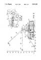
- FIG. 1is a side elevation of a prior art aerial lift in storage position on a vehicle and showing certain other positions of parts thereof in phantom lines;
- FIG. 2is a side elevation of the novel aerial lift of the present invention again showing the storage position on a vehicle and illustrating certain other positions of the boom available with the present invention;
- FIG. 3is a partial side elevation of the upper and lower booms pivotally coupled together and the variable length link that is coupled between the inner end of the outer boom and the rotatable support on the vehicle;
- FIG. 4is a top or plan view of the variable length link means of the present device.
- FIG. 5is a side elevation of the novel variable length link means of the present invention.
- FIG. 6is a top view of the novel nozzle used in the present invention.
- FIG. 7is a front view of the nozzle illustrated in FIG. 6;
- FIG. 8is a side elevation of the novel nozzle illustrated generally in FIGS. 6 and 7;
- FIG. 9is another side elevation of the novel nozzle assembly illustrating movement thereof in the vertical plane.
- FIG. 1An aerial lift of the prior art is shown in FIG. 1 and may be mounted on a vehicle V as illustrated.
- the liftmay include a turntable T conveniently rotatable 360° and on which a lower boom L and a pair of links K are pivotally mounted at different positions.
- a hydraulic cylinder Cwhich may be pivotally mounted to turntable T at the same position as the link K, is also pivotally attached to lower boom L to elevate the same.
- a knee joint Jis mounted on and fixedly receives a portion of the inner end of upper boom U while both the lower boom L and the link K are pivotally connected to the knee joint J.
- a slightly modified parallelogramis formed by lines connecting the pivot points at the inner and outer ends of the lower boom and link.
- the parallelogramis formed by the lines between the outer pivot points of the lower boom and links and the inner pivot points of the lower boom and links, respectively.
- An extensible boom Eis slidable outwardly and inwardly from an upper boom U while a workmens cage or basket B is pivotally supported by the extensible boom. As in FIG. 1, the extensible boom E may be moved outwardly to a position E' with the basket B thereby being moved to a position B'.
- the hydraulic cylinder Cmay be extended to move the lower boom L upwardly to a position L' which automatically moves the joint J to a position J' and the upper boom U to a position U' with the links K moving to a position K' and determining the angularity between the lower boom and the upper boom.
- FIG. 2illustrates a vehicle 10 that may include a turntable T, conveniently rotatable 360° about a vertical axis, on which a lower boom 12 and a pair of links 14 are pivotally mounted at different positions.
- a hydraulic cylinder 16which may have one end pivotally attached to the turntable T at the same position as the links 14, is also pivotally attached at the other end to the lower boom 12 to elevate or lower the same.
- a knee joint 18is rigidly mounted on, or may be integrally formed with, a portion of the inner end of an upper boom 20. Both the lower boom 12 and the links 14 are pivotally connected to the knee joint 18 at spaced locations.
- An extensible boom 22is slidable outwardly and inwardly within the upper boom 20.
- a nozzle assembly 24is pivotally supported by the extensible boom 22.
- the lower boom 12 and the upper boom 20are nested on top of the vehicle 10 as illustrated in FIG. 2.
- piston 16is actuated to move lower boom 12 upwardly, the upper boom 20 has a tendency to move as disclosed by the prior art device in FIG. 1 because of link 14.
- link 14has a selectively variable length and is formed in two sections slidable within each other as will be seen more clearly hereafter in relation to FIGS. 4 and 5.
- a hydraulic piston 26couples the outer end of links 14 which are coupled to the knee joint 18 with the lower end of links 14 which are coupled to the turntable T.
- the length of the links 14changes, thus pivoting the upper boom 20 about pivot point 28 and causing the upper boom 20 and its extension 22 to be moved upwardly or downwardly as indicated in FIG. 2.
- the existing unitcan be pivoted upwardly a distance 50 feet above ground and downwardly until the nozzle assembly 24 is at ground level.
- the turntable Tis rotatably mounted to the vehicle as described earlier.
- the link 14has an outer end 30 and an inner end 32.
- the inner end 32is pivotally attached to the rotatable turntable T at pivot point 34 while the outer and 30 of link 14 is attached to the knee joint 18 at pivot point 36.
- the hydraulic cylinder 26is coupled at one end to the outer end 30 of the link 14 at point 38 while the other end of the hydraulic cylinder 26 is coupled to the inner portion 32 of link 14 at point 40.
- the inner portion 32 of link 14is telescopically inserted on the inside of the outer portion 30 of link 14 as illustrated by joint 33.
- the hydraulic cylinder 16is pivotally coupled at its inner end to the pivot point 34 on turntable T while its outer arm or rod is attached at point 41 to the lower boom 12.
- Upper boom 20is pivotally attached at point 28 to lower boom 12.
- a water supply pipe 42includes a swivel joint and receives water at the center point of the rotatable turntable T and passes it through a flexible hose 44 or any other desired connection to the outside of boom 12. It travels in a pipe 43 on the other side of boom 12 as shown in phantom lines to and is connected with the rotatable joint 46 in the knee joint 18.
- Joint 46couples pipe 43 to the fluid pipe 48 which continues longitudinally on the outside of upper boom 20 to carry fluid such as water to the nozzle assembly 24 on the outer end of boom 20.
- a pipe 49is slidable within pipe 48 and is connected to extensible boom portion 22 for movement therewith.
- pipe 49moves inwardly and outwardly with respect to pipe 48.
- lower boom 12begins to pivot upwardly about pivot point 50 where its inner end is attached to turntable T. If link 14 does not change its length, movement of the lower boom will cause the upper boom 20 to pivot above pivot point 28, thus moving upper boom 20 away from lower boom 12 as illustrated in the prior art by FIG. 1.
- link 14does not change its length, movement of the lower boom will cause the upper boom 20 to pivot above pivot point 28, thus moving upper boom 20 away from lower boom 12 as illustrated in the prior art by FIG. 1.
- upper boom 20can be pivoted about the point 28 with respect to lower boom 12 thus enabling the boom 20 to assume any of the positions illustrated in FIG. 2.
- the upper and lower booms 12 and 20When the upper and lower booms 12 and 20 are in the bedded position illustrated in FIG. 2, they are positioned directly over the cab roof of the vehicle.
- the upper boom 20can be extended approximately 16 feet in front of the cab while in the bedded position. This allows the operator to push any impending or approaching fire back away from the vehicle thus adding to the safety of the operating personnel.
- the operatorWhen the need arises to elevate the nozzle, the operator simply moves a single joystick hydraulic control in the vehicle cab in the proper direction to elevate the upper boom to a height of 50 feet or more with the existing unit.
- the nozzle device 24is compact and versatile and can be positioned inside the door of an aircraft to deluge the interior if necessary.
- the tilt down feature of the boomallows the nozzle assembly 24 to be lowered to ground level. This feature will position the nozzle device in various positions below the horizontal plane.
- variable length link assembly 14includes a hydraulic cylinder 26 installed between the two telescopic pivot links 52 and 54.
- the link 52includes an outer portion 30 and a telescoping inner portion 32.
- link 54includes an outer portion 30' and a telescoping inner portion 32'.
- the assembly 14provides the capability to tilt the boom at an angle up to 40° below horizontal.
- the telescoping pivot links 52 and 54are constructed of steel alloy testing at 46,000 psi or equal suitable material and is equipped with a bushing. The combination of articulation and tilt down allows the nozzle to be placed at ground level approximately 15 to 20 feet in front of the vehicle.
- the upper boom 20consists of a rectangular steel alloy tube outer section with an aluminum alloy telescoping inner section (or other materials suitable for the construction).
- the upper boom 20is adequately reinforced to sustain all anticipated loads and nozzle reaction forces at full flow in all sweep directions.
- the extension and retraction of the upper boomis accomplished by a hydraulic cylinder providing a fully extended stroke of approximately 16 feet.
- the telescoping sectionis supported by phenolic pads for smooth, wear-free operation. Hydraulic hose and electrical lines are carried within a flexible tube support. All hydraulic hoses and electrical cables are contained inside the upper boom assembly 20 for maximum protection.
- the waterway piping system 48shall be capable of flowing up to 1,000 gallons per minute with minimum friction loss.
- the waterwaybegins with a nominal 4-inch ID system containing a flexible connection at the base and extending along the lower boom section as light weight rigid tubing.
- the 4 inch waterwaypasses through the articulating section with the swivel assembly 46 and extends along the outside of the upper boom section 20.
- a 31/4" nominal ID telescoping waterwayis provided on the upper boom assembly inside the 4-inch piping consisting of rigid tubing. Telescoping sections are sealed by special polypropylene glands 158 (FIG. 9).
- the waterwayterminates with a 3-inch fitting for the nozzle sweep assembly 24.
- the nozzle sweep assembly 24consists of a 3 inch ID double swivel unit allowing the nozzle to sweep in both horizontal and vertical planes.
- the waterway 48turns at a first right angle and couples into a first swivel 52 and then turns a second right angle into a second swivel 54.
- the first swivel 52has a sprocket 60 driven by a chain 58 which moves the nozzle 56 in a vertical plane with respect to the boom as can be seen best in FIG. 8.
- the drive systemcan cause the nozzle 56 to move upwardly above horizontal 45° and downwardly below horizontal 180° for a total movement of 225°. As can be seen in FIGS.
- a motor 62drives a worm gear 64 that couples to gear 66 at the second swivel joint 54.
- motor 62can swivel the nozzle 56 90° in each direction from the axis of the boom for a total of 180°.
- the roller chain 58rides on and is driven by a sprocket gear 154 which, in turn, is connected to an electric drive motor 150 through a gear box 152.
- Horizontal and vertical travel motionscan be adjusted by placement of stops in the drive system that actuate a slip clutch in the drive motor.
- a halon or other specific agent nozzle 70may be attached by means 72 to the nozzle assembly 24 along side the water/foam nozzle 56.
- Nozzle 70receives the agent from a supply tank 17 shown on the vehicle in FIG. 2.
- Pipingconsists of a stainless steel or equal telescoping tube 74.
- Stainless steel swivel fittings 73 and 75 similar to those described for the nozzle assembly 24are installed to allow the auxiliary nozzle to rotate and elevate in conjunction with the movements of nozzle assembly 24.
- Flexible tube 76couples telescopic tube 74 to swivel fitting 75.
- an elongated piercing nozzle 71may be used instead of using the short halon nozzle 70.
- This nozzlehas a piercing head 65, a sprayer unit 67 and a stop collar 69.
- the stop collar 69may have an outside diameter of approximately 5 inches, while the nozzle 71 itself may have an outside diameter of 2 inches. These diameters are for example only and may vary.
- the stop collar 69is rigidly attached to the nozzle 71 such as, for instance, by welding or being integrally formed therewith.
- the stop collar 69sits just in front of nozzle 56. The purpose of the stop collar 69 is to protect the nozzle assembly when the piercing nozzle 71 is used to penetrate a structure wall or container.
- the nozzle 71may use any special agents, such as halon or dry chemicals in conjunction with the piercing point 65 and the spray unit 67.
- the operatorcan approach an object or structure on fire, such as an airplane, and extend the boom with the piercing nozzle extending in the front thereof and penetrate the fuselage wall to spray the fire retardant on the interior of the plane.
- the length of the nozzle 61 from the attachment point at 63 where it may be screwed to the tube 74is approximately 24 inches. It may also extend in front of the stop collar 69 approximately 18 inches.
- Heat sensor 164may be of any well-known type in the art.
- a proximity sensor 170 mounted on attachment means 72can be utilized to give the operator an indication of the distance from the nozzle assembly to the structure.
- the operatorby using the heat sensor 164, can tell where the hot spot is without being able to see the structure. He can then extend the nozzle end of the boom into the smoke and utilize the proximity sensor 170 to determine the distance of the nozzle from the structure even though he cannot see the structure.
- the proximity detectormay be of the type entitled "Ultra-Sonic Tattletale Safety System", a trademark for a system for use on vehicles.
- the heat sensor 164may be of any type well known in the art and in particular such as the type sold under the trademark “Life Sight", which works on the principle of radiated heat. It "sees” heat and creates a small television heat image that allows the user to see through smoke, utilizing the fact that thermal energy is not blocked by smoke particles as is ordinary light. With this device, any object that is 0.5° F. different from the surrounding area can be detected.
- a video camera transmitter 160is mounted on the mounting structure 72 so that the operator can raise the boom and position it in the vertical and horizontal planes to scan the area of concern. By raising the boom, and maneuvering the nozzle assembly, the camera can be caused to view areas and transmit pictures to a receiver in the vehicle so that the operator can "see” the entire area, thus aiding in the ability to control a fire.
- the video camera 160may be of any type well-known in the art which is controlled electrically in any well-known manner from the cab of the vehicle.
- present nozzles used on the aerial assembliesdo not have the capability of changing the flow quantity except by changing pressure.
- the only way to change it in the prior artis to simply change the volume of water flowing by restricting water flow through a valve on the side of the supply vehicle.
- nozzle 56is of a type well-known in the art, but not used on remote aerial booms, that control flow quantity by restricting the orifice and control the flow pattern thereby varying the fluid flow direction through the orifice.
- Such a nozzleis sold by Feecon Corporation.
- electric driven motors 166 and 168are mounted on each side of the nozzle pipe 68 and are electrically controlled from the cab.
- Electric motor 166changes the orifice restriction of the Feecon Corporation nozzle to control the flow quantity of fluid at the output of nozzle 56.
- Electric motor 168also operated from the cab in a well-known manner, controls the flow pattern by varying the direction of fluid flow through the nozzle. Thus it can be a fine spray pattern or a concentrated stream. Thus, the quantity of fluid flow can be controlled without changing the pressure.
- two combination flood/spot lights 77 and 79 with one million peak candle powereach may be attached to the nozzle assembly 24.
- each lighthas quartz halogen bulbs and operates on a 12 volt system.
- the lightsmay be remotely switched from spot to flood modes.
- the flood modeprovides full 150° illumination.
- the complete systemis weather proofed and the lights rotate and elevate with the nozzle movement to provide illumination of the water/foam stream or act as an independent remote controlled light tower. Provision has also been made to accommodate other electrically or pneumatically operated devices that may be located at or near the end of the boom.
- a novel aerial boom systemwhich allows a vehicle to be operated for a full range of responsibilities.
- the systemis designed to be placed in operation during the roll in approach to a fire such as an aircraft incident and to begin discharging agent on the fire without restricting the mobility of the vehicle.
- the engine driven or P.T.O. driven hydraulic systemallows the nozzle to be operated without disruption of the vehicle normal operation.
- the all electric control nozzlecan be utilized much like a standard roof mounted turret.
- Joystick controlssimplify the operation.
- Joysticksincorporate potentiometers to allow proportional adjustment of hydraulic cylinders as is well known in the art. Capability is provided for preprogrammed boom/nozzle movements.
- the assemblyWhen the assembly is in the bedded position, it is positioned directly over the cab roof.
- the boomcan be extended approximately 16 feet in front of the cab while in the bedded position. This allows the driver/operator to push any impending or approaching fire back away from the vehicle, thus adding to the safety of the operating personnel.
- the operatorWhen the need arises to elevate the nozzle, the operator simply moves a single joystick in the proper direction. Hydraulic pressure then elevates the boom to a height of 50 feet or more on existing models.
- the nozzle deviceis compact and versatile and can be positioned inside the doorway of an aircraft to deluge the interior if necessary.
- the additional halon or other auxiliary agent systemgives greater depth to the overall performance.
- the halon auxiliary agent nozzleis attached to the water/foam nozzle and is positioned by utilizing the joystick control that moves the water/foam nozzle.
- the nozzlehas the capability of rotating 90° either side of the center line of the boom. This allows the nozzle to be rotated 180° on the horizontal plane. It can also be rotated in the vertical plane plus 45° above horizontal and minus 180° below horizontal in the vertical plane.
- the two one million candle power spot/flood lightsenhance nighttime capabilities.
- the power for the lightis supplied by a switch on the instrument panel.
- Auxiliary electric or pneumatic functionscan be added to the end of the boom for other fire fighting or rescue operations.
- Joystick controlsare capable of proportional hydraulic cylinder movement and can be combined with other electronic components for preprogrammed nozzle/boom movements.
- the tilt down feature of the nozzleallows the nozzle to be lowered to ground level. This feature positions the nozzle device in various locations below the horizontal plane to address a variety of tasks.
- the piercing nozzleallows the operator of the boom to extend the piercing nozzle through the wall of a structure to inject the fire-fighting chemicals directly inside the structure containing the fire.
- the use of the stop collarprevents the nozzle assembly from being damaged by inserting the piercing nozzle too great a distance into the structure.
- a heat sensorthe operator can scan the structure with the boom movements and the nozzle movements to find the hot spots.
- the heat sensorcan locate the hot spots even though the structure is surrounded by heavy smoke.
- the proximity sensorcan allow the operator, after locating the hot spots, to insert the piercing nozzle through the wall at that point, even though the wall cannot be seen because the proximity sensor indicates to the user the distance of the end of the boom from the structure.
- the remote control of the nozzle by two electric motorsallows the user to vary not only the volume of water being used, but also the flow pattern.
Landscapes
- Health & Medical Sciences (AREA)
- Public Health (AREA)
- Business, Economics & Management (AREA)
- Emergency Management (AREA)
- Forklifts And Lifting Vehicles (AREA)
- Fire-Extinguishing By Fire Departments, And Fire-Extinguishing Equipment And Control Thereof (AREA)
Abstract
Description
Claims (25)
Priority Applications (3)
| Application Number | Priority Date | Filing Date | Title |
|---|---|---|---|
| US07/723,577US5211245A (en) | 1991-07-01 | 1991-07-01 | Vehicle mounted aerial lift |
| CA002067649ACA2067649C (en) | 1991-07-01 | 1992-04-30 | Vehicle mounted aerial lift |
| US08/014,548US5301756A (en) | 1991-07-01 | 1993-02-08 | Vehicle mounted aerial lift |
Applications Claiming Priority (1)
| Application Number | Priority Date | Filing Date | Title |
|---|---|---|---|
| US07/723,577US5211245A (en) | 1991-07-01 | 1991-07-01 | Vehicle mounted aerial lift |
Related Child Applications (1)
| Application Number | Title | Priority Date | Filing Date |
|---|---|---|---|
| US08/014,548Continuation-In-PartUS5301756A (en) | 1991-07-01 | 1993-02-08 | Vehicle mounted aerial lift |
Publications (1)
| Publication Number | Publication Date |
|---|---|
| US5211245Atrue US5211245A (en) | 1993-05-18 |
Family
ID=24906838
Family Applications (2)
| Application Number | Title | Priority Date | Filing Date |
|---|---|---|---|
| US07/723,577Expired - LifetimeUS5211245A (en) | 1991-07-01 | 1991-07-01 | Vehicle mounted aerial lift |
| US08/014,548Expired - LifetimeUS5301756A (en) | 1991-07-01 | 1993-02-08 | Vehicle mounted aerial lift |
Family Applications After (1)
| Application Number | Title | Priority Date | Filing Date |
|---|---|---|---|
| US08/014,548Expired - LifetimeUS5301756A (en) | 1991-07-01 | 1993-02-08 | Vehicle mounted aerial lift |
Country Status (2)
| Country | Link |
|---|---|
| US (2) | US5211245A (en) |
| CA (1) | CA2067649C (en) |
Cited By (69)
| Publication number | Priority date | Publication date | Assignee | Title |
|---|---|---|---|---|
| US5341999A (en)* | 1992-05-07 | 1994-08-30 | Rosenbauer International Aktiengesellschaft | Fire brigade truck |
| WO1994027484A1 (en)* | 1993-06-01 | 1994-12-08 | Johnson Edward P | Method and apparatus for rejuvenating a drainfield or dry well |
| US5788158A (en)* | 1996-07-31 | 1998-08-04 | Crash Rescue Equipment Service, Inc. | Automatic levelling fluid nozzle for aerial boom |
| WO1998038612A1 (en)* | 1997-02-27 | 1998-09-03 | Shaw Jack B | Crane safety devices and methods |
| US5839664A (en)* | 1996-07-31 | 1998-11-24 | Crash Rescue Equipment Service, Inc, | Fluid discharge nozzle assembly |
| US5899276A (en)* | 1997-09-10 | 1999-05-04 | Crash Rescue Equipment Service, Inc. | Bumper-mounted extensible turret |
| US6003782A (en)* | 1996-12-31 | 1999-12-21 | Kim; Jitae | Aerial spray system |
| US6193170B1 (en) | 2000-01-07 | 2001-02-27 | John J. Fitzgerald | Ready-access fire-fighting nozzle and method |
| US6283699B1 (en)* | 1995-03-31 | 2001-09-04 | Ross Allan Simpson | Container handling systems |
| RU2179048C2 (en)* | 2000-04-24 | 2002-02-10 | Царев Анатолий Михайлович | Nozzle-type fire-extinguisher |
| US6549139B2 (en) | 1997-02-27 | 2003-04-15 | Jack B. Shaw, Jr. | Crane safety device and methods |
| US20030163230A1 (en)* | 1999-07-30 | 2003-08-28 | Oshkosh Truck Corporation | Turret operator interface system and method for a fire fighting vehicle |
| US20030163228A1 (en)* | 1999-07-30 | 2003-08-28 | Oshkosh Truck Corporation | Turret targeting system and method for a fire fighting vehicle |
| US20030163229A1 (en)* | 1999-07-30 | 2003-08-28 | Oshkosh Truck Corporation | Turret envelope control system and method for a fire fighting vehicle |
| US20030171854A1 (en)* | 1999-07-30 | 2003-09-11 | Oshkosh Truck Corporation | Turret deployment system and method for a fire fighting vehicle |
| US20030214415A1 (en)* | 1997-02-27 | 2003-11-20 | Shaw Jack B. | Crane safety devices and methods |
| US6659374B1 (en)* | 1998-05-05 | 2003-12-09 | Goldenvale Pty Ltd. | Spray head |
| EP1369145A1 (en) | 2002-06-03 | 2003-12-10 | Bronto Skylift OY AB | Arrangement for fire fighting |
| US20030230412A1 (en)* | 2002-06-13 | 2003-12-18 | Oshkosh Truck Corporation | Apparatus and method to facilitate maintenance of a work vehicle |
| US20040003929A1 (en)* | 2002-07-02 | 2004-01-08 | Darrell Graf | Firefighting system |
| US20040039510A1 (en)* | 1999-07-30 | 2004-02-26 | Oshkosh Truck Corporation | Control system and method for an equipment service vehicle |
| US20040055765A1 (en)* | 2002-07-31 | 2004-03-25 | Dillman Bruce A. | Method of extinguishing fires |
| US20040069865A1 (en)* | 2002-02-28 | 2004-04-15 | Oshkosh Truck Corporation | Turret positioning system and method for a fire fighting vehicle |
| US6744372B1 (en) | 1997-02-27 | 2004-06-01 | Jack B. Shaw | Crane safety devices and methods |
| US20040199302A1 (en)* | 2001-12-21 | 2004-10-07 | Oshkosh Truck Corporation | Turret control system and method for a fire fighting vehicle |
| US6808025B2 (en) | 1999-09-10 | 2004-10-26 | Schwing America, Inc. | Fire-fighting system having improved flow |
| US6860332B1 (en) | 2002-06-13 | 2005-03-01 | Oshkosh Truck Corporation | Fluid dispensing arrangement and skid pan for a vehicle |
| US20050077381A1 (en)* | 2003-10-14 | 2005-04-14 | Eric Combs | Fire-fighting monitor |
| US20060022001A1 (en)* | 2004-07-29 | 2006-02-02 | Oshkosh Truck Corporation | Aerial boom attachment |
| US20060021764A1 (en)* | 2004-07-29 | 2006-02-02 | Oshkosh Truck Corporation | Piercing tool |
| US20060032701A1 (en)* | 2004-07-29 | 2006-02-16 | Oshkosh Truck Corporation | Composite boom assembly |
| US20060032702A1 (en)* | 2004-07-29 | 2006-02-16 | Oshkosh Truck Corporation | Composite boom assembly |
| US20060065411A1 (en)* | 2004-09-28 | 2006-03-30 | Oshkosh Truck Corporation | Firefighting agent delivery system |
| US20060086566A1 (en)* | 2004-07-29 | 2006-04-27 | Oshkosh Truck Corporation | Boom assembly |
| US7055613B1 (en) | 2003-03-12 | 2006-06-06 | Schwing America, Inc. | Self leveling boom system with rotatable working assembly |
| US20070034389A1 (en)* | 2005-08-10 | 2007-02-15 | Crash Rescue Equipment Service, Inc. | Extensible aerial boom having two independently operated fluid nozzles |
| US20070088469A1 (en)* | 2005-10-04 | 2007-04-19 | Oshkosh Truck Corporation | Vehicle control system and method |
| WO2008019660A1 (en)* | 2006-08-12 | 2008-02-21 | Christof Burkart | Extinguishing device |
| US20080060822A1 (en)* | 2006-09-13 | 2008-03-13 | Spartan Motors, Inc. | Vehicle mounted fire and rescue boom |
| US20080099213A1 (en)* | 2006-10-19 | 2008-05-01 | Oshkosh Truck Corporation | Pump system for a firefighting vehicle |
| US20080099212A1 (en)* | 2006-10-17 | 2008-05-01 | Ted-Xuan Do | Modified Fire Fighting Truck |
| NL1034346C2 (en)* | 2007-09-06 | 2009-03-09 | Robert Timmers | Firefighting, communications and rescue lance for use on vehicle for firefighting operations in building, has extendable head mounted on hydraulic, computer controlled robot arm, and point with various fire extinguishing agents |
| WO2009129875A1 (en)* | 2008-04-23 | 2009-10-29 | Caccialanza & C. S.P.A. | Fire extinguishing monitor and method |
| US20100044059A1 (en)* | 2007-04-12 | 2010-02-25 | Josef Mikota | Device for use in fire-fighting operations |
| US7711460B2 (en) | 2001-01-31 | 2010-05-04 | Oshkosh Corporation | Control system and method for electric vehicle |
| US20100218960A1 (en)* | 2002-07-31 | 2010-09-02 | Dillman Bruce A | Method of Extinguishing Fires |
| ITMI20090484A1 (en)* | 2009-03-27 | 2010-09-28 | Giuseppe Panseri | SPRAYER EQUIPMENT |
| US7835838B2 (en) | 1999-07-30 | 2010-11-16 | Oshkosh Corporation | Concrete placement vehicle control system and method |
| US20130206429A1 (en)* | 2012-02-11 | 2013-08-15 | Christopher Sullivan | Method and Apparatus for Fire Fighting Efficiency and Safety |
| US20140103698A1 (en)* | 2012-10-17 | 2014-04-17 | Bo Feng | Horizontally rotatable multi-knuckle boom |
| US20140202722A1 (en)* | 2013-01-18 | 2014-07-24 | GelTech Solutions, Inc. | Device for Treating Manhole Electrical Fires |
| WO2014173609A1 (en)* | 2013-04-22 | 2014-10-30 | Manitowoc Crane Group Frances Sas | Sensor-based monitoring of wind direction and thermal radiation for a mobile work appliance |
| US20150096770A1 (en)* | 2013-10-03 | 2015-04-09 | GelTech Solutions, Inc. | Device for Distribution of Fire Suppressant |
| US20160032649A1 (en)* | 2014-07-29 | 2016-02-04 | Gimaex International | Telescopic Ladder Comprising Ladder Sections Of Different Densities |
| FR3037293A1 (en)* | 2015-06-12 | 2016-12-16 | Alain Villalonga | VEHICLE COMPRISING A DEVICE FOR SPRAYING A LIQUID, THE VEHICLE BEING INTENDED TO BE USED FOR THE CLEANING OF BUILDINGS |
| US9656842B2 (en) | 2012-02-11 | 2017-05-23 | Christopher Sullivan | Method and apparatus for fire fighting efficiency and safety |
| US20170296850A1 (en)* | 2012-04-03 | 2017-10-19 | Juan Manuel Medina | Multi TFI with fluid sprinklers |
| US20180095345A1 (en)* | 2014-12-12 | 2018-04-05 | Chips Unlimited, Inc. | Systems and methods for mounting photographic equipment |
| CN108785920A (en)* | 2018-04-02 | 2018-11-13 | 江苏卡威专用汽车制造有限公司 | A kind of hoisting system of fire fighting truck |
| US10221055B2 (en) | 2016-04-08 | 2019-03-05 | Oshkosh Corporation | Leveling system for lift device |
| US10286239B2 (en) | 2017-02-08 | 2019-05-14 | Oshkosh Corporation | Fire apparatus piercing tip ranging and alignment system |
| WO2019152394A1 (en)* | 2018-01-31 | 2019-08-08 | Spartan Motors, Inc. | Multi-stance aerial device control and display |
| US10434995B2 (en) | 2012-03-26 | 2019-10-08 | Oshkosh Defense, Llc | Military vehicle |
| US10799735B2 (en) | 2018-02-09 | 2020-10-13 | Seagrave Fire Apparatus, Llc | Fire apparatus vehicle with turret support arrangement |
| JP2021049368A (en)* | 2020-12-08 | 2021-04-01 | ホーチキ株式会社 | In-tunnel fire hydrant facility and fire hydrant device |
| US20210146175A1 (en)* | 2019-11-19 | 2021-05-20 | They | Fire Suppression Device and System |
| NO345922B1 (en)* | 2020-04-30 | 2021-10-25 | Powerfog As | High energy fire fighting system |
| USD966958S1 (en) | 2011-09-27 | 2022-10-18 | Oshkosh Corporation | Grille element |
| US12038774B2 (en)* | 2016-05-23 | 2024-07-16 | Iveco Magirus Ag | Control center for an aerial device comprising a rotatable joystick |
Families Citing this family (46)
| Publication number | Priority date | Publication date | Assignee | Title |
|---|---|---|---|---|
| US5447203A (en)* | 1991-07-17 | 1995-09-05 | Mcloughlin; John E. | Remotely actuated firefighting nozzle |
| US5626194A (en)* | 1994-09-20 | 1997-05-06 | Fav, Inc. | Fire fighting system |
| US5836398A (en)* | 1994-09-20 | 1998-11-17 | Fav, Inc. | Vehicle mounted fire fighting system |
| FI100229B (en)* | 1996-05-27 | 1997-10-31 | Markku Ahti Limingoja | Method and device for forcible stopping of other vehicles |
| US5860479A (en)* | 1996-07-12 | 1999-01-19 | Lafollette; David A. | Remote firefighting apparatus |
| US5913367A (en)* | 1996-09-06 | 1999-06-22 | Hampton; Lawrence M. | Aircraft penetrator |
| SE509895C2 (en)* | 1997-08-15 | 1999-03-22 | Cold Cut Systems Svenska Ab | Method and equipment in emergency services |
| US6104305A (en)* | 1997-11-14 | 2000-08-15 | The Will-Burt Company | Pole alarm system |
| US6109360A (en)* | 1998-02-04 | 2000-08-29 | Premier Farnell Corp. | Fire fighting monitor |
| FR2804033A1 (en)* | 2000-01-21 | 2001-07-27 | Claude Louit | Aerial ladder for firefighting has film camera carried at end of telescopic boom which transmits images to screen |
| US6311781B1 (en) | 2000-04-03 | 2001-11-06 | Karic Ventures Ltd. | Ballast tank for excavating equipment |
| US7456750B2 (en) | 2000-04-19 | 2008-11-25 | Federal Express Corporation | Fire suppression and indicator system and fire detection device |
| US6446731B1 (en)* | 2000-12-20 | 2002-09-10 | Joseph J. Soroski | Smoke evacuating fire vehicle |
| US20030132010A1 (en) | 2002-01-15 | 2003-07-17 | Lancaster David W. | Apparatus and method for extinguishing fires |
| US7114575B2 (en)* | 2003-01-22 | 2006-10-03 | Viasa Incorporated, S.A. De C.V. | Method and apparatus for extinguishing fires in storage vessels containing flammable or combustible liquids |
| US7191964B2 (en)* | 2003-04-02 | 2007-03-20 | Elkhart Brass Manufacturing Company, Inc. | Fire-fighting monitor with remote control |
| US6994282B2 (en)* | 2003-04-02 | 2006-02-07 | Elkhart Brass Mfg. Co. | Radio controlled liquid monitor |
| US20080061172A1 (en) | 2006-09-12 | 2008-03-13 | Trapp James M | High pressure monitor |
| US7017832B1 (en)* | 2003-04-23 | 2006-03-28 | Pro-Fab, Inc. | Piercing hose nozzle |
| US20040256497A1 (en)* | 2003-06-06 | 2004-12-23 | Sharkey Douglas Allan | High performance nozzle |
| FI115198B (en)* | 2003-08-22 | 2005-03-31 | Bronto Skylift Oy Ab | Fire extinguishing procedure and plant |
| US8807233B2 (en)* | 2003-08-22 | 2014-08-19 | Bronto Skylift Oy Ab | Method and equipment for fire-fighting |
| US20050194367A1 (en)* | 2004-03-02 | 2005-09-08 | Fredrick William G.Jr. | System and method for remote controlled actuation of laser processing head |
| US7137456B2 (en)* | 2004-03-10 | 2006-11-21 | Moses Linnie L | Firefighting equipment |
| US20060283981A1 (en)* | 2005-06-16 | 2006-12-21 | Mead William T | Spray coating nozzle assembly for coating remote areas |
| US7810577B2 (en)* | 2005-08-30 | 2010-10-12 | Federal Express Corporation | Fire sensor, fire detection system, fire suppression system, and combinations thereof |
| US7984863B1 (en)* | 2005-08-31 | 2011-07-26 | Alan E. Berberick | High-rise building fire fighting portable shaft system |
| MX2008012106A (en)* | 2006-03-22 | 2008-11-14 | Federal Express Corp | Fire suppressant device and method, including expansion agent. |
| US8037844B2 (en)* | 2007-10-31 | 2011-10-18 | Nordson Corporation | Spray gun having display and control members on gun |
| US20100012751A1 (en)* | 2008-07-16 | 2010-01-21 | Warren Marc R | Laser Assisted Aiming System for Fluid Nozzles |
| US8606373B2 (en)* | 2009-04-22 | 2013-12-10 | Elkhart Brass Manufacturing Company, Inc. | Firefighting monitor and control system therefor |
| AU2009347562B2 (en)* | 2009-06-02 | 2016-01-28 | Haviland Nominees Pty Ltd | Vehicle mounted unmanned water cannon |
| AU2009100534B4 (en)* | 2009-06-02 | 2010-05-20 | Magnum Rental Pty Ltd | Vehicle mounted unmanned water cannon |
| US9557199B2 (en) | 2010-01-21 | 2017-01-31 | Elkhart Brass Manufacturing Company, Inc. | Firefighting monitor |
| US9186531B2 (en)* | 2010-04-15 | 2015-11-17 | Elkhart Brass Manufacturing Company, Inc. | Fire fighting monitor |
| CZ304752B6 (en)* | 2011-03-30 | 2014-09-24 | SLEZSKÝ VÝZKUM s.r.o. | Extinguishing and penetration unit |
| CZ304753B6 (en)* | 2011-03-30 | 2014-09-24 | SLEZSKĂť VĂťZKUM s.r.o. | Turntable of manipulator supporting arm |
| MY185328A (en) | 2012-07-09 | 2021-05-05 | Rigdeluge Global Ltd | Deluge system |
| US12064654B2 (en) | 2012-07-09 | 2024-08-20 | Rig Deluge Global Limited | Deluge system |
| US10072780B2 (en)* | 2012-08-17 | 2018-09-11 | Elkhart Brass Manufacturing Company, Inc. | Fluid delivery device |
| US9855350B1 (en)* | 2013-02-20 | 2018-01-02 | Kevin James Dahlquist | Fluid dispersal system with integrated functional lighting |
| CN103143518A (en)* | 2013-03-12 | 2013-06-12 | 云南电网公司西双版纳供电局 | Live cleaning tool for contact terminal and contact finger of 110kV disconnecting switch |
| US10118138B2 (en)* | 2014-06-20 | 2018-11-06 | James Timothy Tews | Floating manure agitator with multidirectional agitator nozzles |
| CN105288911B (en)* | 2015-12-02 | 2021-06-15 | 威海广泰空港设备股份有限公司 | Elevating fire truck boarding structure with puncture function |
| CN105251166B (en)* | 2015-12-02 | 2021-06-22 | 威海广泰空港设备股份有限公司 | Fire monitor body structure |
| US20210346742A1 (en)* | 2018-08-02 | 2021-11-11 | Carrier Corporation | Low noise nozzle assembly for fire suppression system |
Citations (15)
| Publication number | Priority date | Publication date | Assignee | Title |
|---|---|---|---|---|
| FR1045281A (en)* | 1951-11-20 | 1953-11-25 | Applevage | Folding crane |
| US3005512A (en)* | 1960-05-31 | 1961-10-24 | Asplundh Tree Expert Co | Aerial supporting structure for line construction and maintenance workers |
| FR1413973A (en)* | 1964-08-31 | 1965-10-15 | Venot & Cie Ets | Improvements made to hook cranes, more specifically to cranes for seaports |
| US3253677A (en)* | 1963-12-24 | 1966-05-31 | Sterling Prec Corp | Vehicle carried boom |
| US3346052A (en)* | 1965-06-09 | 1967-10-10 | Snorkel Fire Equipment Company | Folding boom aerial water delivery apparatus for mobile fire fighting equipment |
| US3367280A (en)* | 1966-03-07 | 1968-02-06 | Royal Industries | Pump |
| US3527362A (en)* | 1968-04-18 | 1970-09-08 | Kenneth W Allen | Crane attachment for backhoe |
| US3599722A (en)* | 1968-12-31 | 1971-08-17 | Snorkel Fire Equipment Co | Remotely controllable fire fighting apparatus |
| US3820606A (en)* | 1973-04-09 | 1974-06-28 | Morita Fire Pump Mfg | High altitude breaking apparatus for fire fighting |
| US3840074A (en)* | 1973-09-17 | 1974-10-08 | Rockwood Systems Corp | Three way remote controlled dual agent fire fighting turret |
| US4222457A (en)* | 1978-03-29 | 1980-09-16 | Simon Engineering Dudley Ltd. | Hydraulic platforms |
| FR2511406A1 (en)* | 1981-08-17 | 1983-02-18 | Obry Jean Marie | Shovel chassis for excavator - incorporates stabilising arms which are vertically and horizontally adjustable |
| US4453672A (en)* | 1982-03-23 | 1984-06-12 | Garnett Edward V | Vehicle mounted aerial lift |
| EP0317891A2 (en)* | 1987-11-25 | 1989-05-31 | Walter Künz | Apparatus for fighting high altitude fires |
| DE3800037A1 (en)* | 1988-01-04 | 1989-07-13 | Oddmund Saxlund | Fire extinguisher |
Family Cites Families (10)
| Publication number | Priority date | Publication date | Assignee | Title |
|---|---|---|---|---|
| US3104720A (en)* | 1963-09-24 | Fire-fighting system and apparatus | ||
| US2251175A (en)* | 1937-05-31 | 1941-07-29 | Tappe Wilhelm | Fire extinguishing apparatus |
| US2813753A (en)* | 1956-03-16 | 1957-11-19 | Fredrick C Roberts | Fog nozzle |
| US2857005A (en)* | 1957-07-19 | 1958-10-21 | Boeing Co | Fire fighting apparatus |
| US3770062A (en)* | 1970-10-12 | 1973-11-06 | American Fire App | Fire fighting apparatus |
| US3762478A (en)* | 1972-03-08 | 1973-10-02 | P Cummins | Remote controlled hazard-fighting vehicle |
| US4219084A (en)* | 1978-04-19 | 1980-08-26 | Nasa | Fire extinguishing apparatus having a slidable mass for a penetrator nozzle |
| US4453627A (en)* | 1980-02-08 | 1984-06-12 | The E. W. Buschman Co. | Accumulator conveyor |
| GB8332016D0 (en)* | 1983-11-30 | 1984-01-04 | Gloster Saro Ltd | Fire-fighting equipment |
| US4802535A (en)* | 1987-01-27 | 1989-02-07 | Bakke Arlan N | Fire-fighting tool |
- 1991
- 1991-07-01USUS07/723,577patent/US5211245A/ennot_activeExpired - Lifetime
- 1992
- 1992-04-30CACA002067649Apatent/CA2067649C/ennot_activeExpired - Lifetime
- 1993
- 1993-02-08USUS08/014,548patent/US5301756A/ennot_activeExpired - Lifetime
Patent Citations (15)
| Publication number | Priority date | Publication date | Assignee | Title |
|---|---|---|---|---|
| FR1045281A (en)* | 1951-11-20 | 1953-11-25 | Applevage | Folding crane |
| US3005512A (en)* | 1960-05-31 | 1961-10-24 | Asplundh Tree Expert Co | Aerial supporting structure for line construction and maintenance workers |
| US3253677A (en)* | 1963-12-24 | 1966-05-31 | Sterling Prec Corp | Vehicle carried boom |
| FR1413973A (en)* | 1964-08-31 | 1965-10-15 | Venot & Cie Ets | Improvements made to hook cranes, more specifically to cranes for seaports |
| US3346052A (en)* | 1965-06-09 | 1967-10-10 | Snorkel Fire Equipment Company | Folding boom aerial water delivery apparatus for mobile fire fighting equipment |
| US3367280A (en)* | 1966-03-07 | 1968-02-06 | Royal Industries | Pump |
| US3527362A (en)* | 1968-04-18 | 1970-09-08 | Kenneth W Allen | Crane attachment for backhoe |
| US3599722A (en)* | 1968-12-31 | 1971-08-17 | Snorkel Fire Equipment Co | Remotely controllable fire fighting apparatus |
| US3820606A (en)* | 1973-04-09 | 1974-06-28 | Morita Fire Pump Mfg | High altitude breaking apparatus for fire fighting |
| US3840074A (en)* | 1973-09-17 | 1974-10-08 | Rockwood Systems Corp | Three way remote controlled dual agent fire fighting turret |
| US4222457A (en)* | 1978-03-29 | 1980-09-16 | Simon Engineering Dudley Ltd. | Hydraulic platforms |
| FR2511406A1 (en)* | 1981-08-17 | 1983-02-18 | Obry Jean Marie | Shovel chassis for excavator - incorporates stabilising arms which are vertically and horizontally adjustable |
| US4453672A (en)* | 1982-03-23 | 1984-06-12 | Garnett Edward V | Vehicle mounted aerial lift |
| EP0317891A2 (en)* | 1987-11-25 | 1989-05-31 | Walter Künz | Apparatus for fighting high altitude fires |
| DE3800037A1 (en)* | 1988-01-04 | 1989-07-13 | Oddmund Saxlund | Fire extinguisher |
Cited By (143)
| Publication number | Priority date | Publication date | Assignee | Title |
|---|---|---|---|---|
| US5341999A (en)* | 1992-05-07 | 1994-08-30 | Rosenbauer International Aktiengesellschaft | Fire brigade truck |
| WO1994027484A1 (en)* | 1993-06-01 | 1994-12-08 | Johnson Edward P | Method and apparatus for rejuvenating a drainfield or dry well |
| US6283699B1 (en)* | 1995-03-31 | 2001-09-04 | Ross Allan Simpson | Container handling systems |
| US5788158A (en)* | 1996-07-31 | 1998-08-04 | Crash Rescue Equipment Service, Inc. | Automatic levelling fluid nozzle for aerial boom |
| US5839664A (en)* | 1996-07-31 | 1998-11-24 | Crash Rescue Equipment Service, Inc, | Fluid discharge nozzle assembly |
| US6003782A (en)* | 1996-12-31 | 1999-12-21 | Kim; Jitae | Aerial spray system |
| US20050017867A1 (en)* | 1997-02-27 | 2005-01-27 | Shaw Jack B. | Crane safety devices and methods |
| US6140930A (en)* | 1997-02-27 | 2000-10-31 | Shaw; Jack B. | Crane safety devices and methods |
| US20030214415A1 (en)* | 1997-02-27 | 2003-11-20 | Shaw Jack B. | Crane safety devices and methods |
| WO1998038612A1 (en)* | 1997-02-27 | 1998-09-03 | Shaw Jack B | Crane safety devices and methods |
| US6549139B2 (en) | 1997-02-27 | 2003-04-15 | Jack B. Shaw, Jr. | Crane safety device and methods |
| US6744372B1 (en) | 1997-02-27 | 2004-06-01 | Jack B. Shaw | Crane safety devices and methods |
| US6894621B2 (en) | 1997-02-27 | 2005-05-17 | Jack B. Shaw | Crane safety devices and methods |
| US20040026348A1 (en)* | 1997-02-27 | 2004-02-12 | Shaw Jack B. | Crane safety devices and methods |
| US5899276A (en)* | 1997-09-10 | 1999-05-04 | Crash Rescue Equipment Service, Inc. | Bumper-mounted extensible turret |
| US6659374B1 (en)* | 1998-05-05 | 2003-12-09 | Goldenvale Pty Ltd. | Spray head |
| US7006902B2 (en) | 1999-07-30 | 2006-02-28 | Oshkosh Truck Corporation | Control system and method for an equipment service vehicle |
| US20070185625A1 (en)* | 1999-07-30 | 2007-08-09 | Oshkosh Truck Corporation | Turret envelope control system and method for a fire fighting vehicle |
| US7184862B2 (en) | 1999-07-30 | 2007-02-27 | Oshkosh Truck Corporation | Turret targeting system and method for a fire fighting vehicle |
| US7162332B2 (en) | 1999-07-30 | 2007-01-09 | Oshkosh Truck Corporation | Turret deployment system and method for a fire fighting vehicle |
| US7127331B2 (en) | 1999-07-30 | 2006-10-24 | Oshkosh Truck Corporation | Turret operator interface system and method for a fire fighting vehicle |
| US20030163229A1 (en)* | 1999-07-30 | 2003-08-28 | Oshkosh Truck Corporation | Turret envelope control system and method for a fire fighting vehicle |
| US20040039510A1 (en)* | 1999-07-30 | 2004-02-26 | Oshkosh Truck Corporation | Control system and method for an equipment service vehicle |
| US20030171854A1 (en)* | 1999-07-30 | 2003-09-11 | Oshkosh Truck Corporation | Turret deployment system and method for a fire fighting vehicle |
| US20030163228A1 (en)* | 1999-07-30 | 2003-08-28 | Oshkosh Truck Corporation | Turret targeting system and method for a fire fighting vehicle |
| US20030163230A1 (en)* | 1999-07-30 | 2003-08-28 | Oshkosh Truck Corporation | Turret operator interface system and method for a fire fighting vehicle |
| US7835838B2 (en) | 1999-07-30 | 2010-11-16 | Oshkosh Corporation | Concrete placement vehicle control system and method |
| US6922615B2 (en) | 1999-07-30 | 2005-07-26 | Oshkosh Truck Corporation | Turret envelope control system and method for a fire fighting vehicle |
| US8095247B2 (en) | 1999-07-30 | 2012-01-10 | Oshkosh Corporation | Turret envelope control system and method for a vehicle |
| US6808025B2 (en) | 1999-09-10 | 2004-10-26 | Schwing America, Inc. | Fire-fighting system having improved flow |
| US6193170B1 (en) | 2000-01-07 | 2001-02-27 | John J. Fitzgerald | Ready-access fire-fighting nozzle and method |
| RU2179048C2 (en)* | 2000-04-24 | 2002-02-10 | Царев Анатолий Михайлович | Nozzle-type fire-extinguisher |
| US7711460B2 (en) | 2001-01-31 | 2010-05-04 | Oshkosh Corporation | Control system and method for electric vehicle |
| US20040199302A1 (en)* | 2001-12-21 | 2004-10-07 | Oshkosh Truck Corporation | Turret control system and method for a fire fighting vehicle |
| US7451028B2 (en)* | 2001-12-21 | 2008-11-11 | Oshkosh Corporation | Turret control system based on stored position for a fire fighting vehicle |
| US7274976B2 (en) | 2002-02-28 | 2007-09-25 | Oshkosh Truck Corporation | Turret positioning system and method for a vehicle |
| US20040069865A1 (en)* | 2002-02-28 | 2004-04-15 | Oshkosh Truck Corporation | Turret positioning system and method for a fire fighting vehicle |
| US7107129B2 (en) | 2002-02-28 | 2006-09-12 | Oshkosh Truck Corporation | Turret positioning system and method for a fire fighting vehicle |
| US6755259B2 (en) | 2002-06-03 | 2004-06-29 | Bronto Skylift Oy Ab | Piercing device for fire-fighting system |
| EP1369145A1 (en) | 2002-06-03 | 2003-12-10 | Bronto Skylift OY AB | Arrangement for fire fighting |
| US7055880B2 (en) | 2002-06-13 | 2006-06-06 | Oshkosh Truck Corporation | Apparatus and method to facilitate maintenance of a work vehicle |
| US6860332B1 (en) | 2002-06-13 | 2005-03-01 | Oshkosh Truck Corporation | Fluid dispensing arrangement and skid pan for a vehicle |
| US20030230412A1 (en)* | 2002-06-13 | 2003-12-18 | Oshkosh Truck Corporation | Apparatus and method to facilitate maintenance of a work vehicle |
| US20040003929A1 (en)* | 2002-07-02 | 2004-01-08 | Darrell Graf | Firefighting system |
| US20060260824A1 (en)* | 2002-07-31 | 2006-11-23 | Dillman Bruce A | Method of extinguishing fires |
| US7055615B2 (en)* | 2002-07-31 | 2006-06-06 | Gulf Coast Hot Mix Equipment Leasing, Inc. | Method of extinguishing fires |
| US20040055765A1 (en)* | 2002-07-31 | 2004-03-25 | Dillman Bruce A. | Method of extinguishing fires |
| US20100218960A1 (en)* | 2002-07-31 | 2010-09-02 | Dillman Bruce A | Method of Extinguishing Fires |
| US7055613B1 (en) | 2003-03-12 | 2006-06-06 | Schwing America, Inc. | Self leveling boom system with rotatable working assembly |
| US20090107687A1 (en)* | 2003-10-14 | 2009-04-30 | Elkhart Brass Manufacturing Company, Inc. | Fire-fighting monitor |
| US20050077381A1 (en)* | 2003-10-14 | 2005-04-14 | Eric Combs | Fire-fighting monitor |
| US7644777B2 (en) | 2003-10-14 | 2010-01-12 | Elkhart Brass Manufacturing Company, Inc. | Fire-fighting monitor |
| US7703545B2 (en) | 2003-10-14 | 2010-04-27 | Elkhart Brass Manufacturing Company, Inc. | Fire-fighting monitor |
| US20060021764A1 (en)* | 2004-07-29 | 2006-02-02 | Oshkosh Truck Corporation | Piercing tool |
| US20060086566A1 (en)* | 2004-07-29 | 2006-04-27 | Oshkosh Truck Corporation | Boom assembly |
| US20060022001A1 (en)* | 2004-07-29 | 2006-02-02 | Oshkosh Truck Corporation | Aerial boom attachment |
| US20060032701A1 (en)* | 2004-07-29 | 2006-02-16 | Oshkosh Truck Corporation | Composite boom assembly |
| US20060032702A1 (en)* | 2004-07-29 | 2006-02-16 | Oshkosh Truck Corporation | Composite boom assembly |
| WO2006037100A1 (en)* | 2004-09-28 | 2006-04-06 | Oshkosh Truck Corporation | Firefighting agent delivery system |
| US7389826B2 (en)* | 2004-09-28 | 2008-06-24 | Oshkosh Truck Corporation | Firefighting agent delivery system |
| US20060065411A1 (en)* | 2004-09-28 | 2006-03-30 | Oshkosh Truck Corporation | Firefighting agent delivery system |
| WO2006101865A1 (en)* | 2005-03-16 | 2006-09-28 | Oshkosh Truck Corporation | Boom assembly |
| US20070034389A1 (en)* | 2005-08-10 | 2007-02-15 | Crash Rescue Equipment Service, Inc. | Extensible aerial boom having two independently operated fluid nozzles |
| US7611075B2 (en)* | 2005-08-10 | 2009-11-03 | Relyea Robert G | Extensible aerial boom having two independently operated fluid nozzles |
| US20070088469A1 (en)* | 2005-10-04 | 2007-04-19 | Oshkosh Truck Corporation | Vehicle control system and method |
| US20100175899A1 (en)* | 2006-08-12 | 2010-07-15 | Christof Burkart | Extinguishing Device |
| WO2008019660A1 (en)* | 2006-08-12 | 2008-02-21 | Christof Burkart | Extinguishing device |
| WO2008032280A3 (en)* | 2006-09-13 | 2008-05-22 | Spartan Motors Inc | Vehicle mounted fire and rescue boom |
| US20080060822A1 (en)* | 2006-09-13 | 2008-03-13 | Spartan Motors, Inc. | Vehicle mounted fire and rescue boom |
| US20080099212A1 (en)* | 2006-10-17 | 2008-05-01 | Ted-Xuan Do | Modified Fire Fighting Truck |
| US7874373B2 (en) | 2006-10-19 | 2011-01-25 | Oshkosh Corporation | Pump system for a firefighting vehicle |
| US20080099213A1 (en)* | 2006-10-19 | 2008-05-01 | Oshkosh Truck Corporation | Pump system for a firefighting vehicle |
| US9480868B2 (en) | 2007-04-12 | 2016-11-01 | Rosenbauer International Aktiengesellschaft | Device for use in fire-fighting operations |
| US20100044059A1 (en)* | 2007-04-12 | 2010-02-25 | Josef Mikota | Device for use in fire-fighting operations |
| US9061168B2 (en)* | 2007-04-12 | 2015-06-23 | Rosenbauer International Aktiengesellschaft | Device for use in fire-fighting operations |
| NL1034346C2 (en)* | 2007-09-06 | 2009-03-09 | Robert Timmers | Firefighting, communications and rescue lance for use on vehicle for firefighting operations in building, has extendable head mounted on hydraulic, computer controlled robot arm, and point with various fire extinguishing agents |
| WO2009129875A1 (en)* | 2008-04-23 | 2009-10-29 | Caccialanza & C. S.P.A. | Fire extinguishing monitor and method |
| ITMI20090484A1 (en)* | 2009-03-27 | 2010-09-28 | Giuseppe Panseri | SPRAYER EQUIPMENT |
| USD1008127S1 (en) | 2011-09-27 | 2023-12-19 | Oshkosh Corporation | Vehicle fender |
| USD966958S1 (en) | 2011-09-27 | 2022-10-18 | Oshkosh Corporation | Grille element |
| US20130206429A1 (en)* | 2012-02-11 | 2013-08-15 | Christopher Sullivan | Method and Apparatus for Fire Fighting Efficiency and Safety |
| US9656842B2 (en) | 2012-02-11 | 2017-05-23 | Christopher Sullivan | Method and apparatus for fire fighting efficiency and safety |
| USD892002S1 (en) | 2012-03-26 | 2020-08-04 | Oshkosh Corporation | Grille element |
| US11273804B2 (en) | 2012-03-26 | 2022-03-15 | Oshkosh Defense, Llc | Military vehicle |
| US12434672B1 (en) | 2012-03-26 | 2025-10-07 | Oshkosh Defense, Llc | Military vehicle |
| US12420752B1 (en) | 2012-03-26 | 2025-09-23 | Oshkosh Defense, Llc | Military vehicle |
| US12384337B1 (en) | 2012-03-26 | 2025-08-12 | Oshkosh Defense, Llc | Military vehicle |
| US12377824B1 (en) | 2012-03-26 | 2025-08-05 | Oshkosh Defense, Llc | Military vehicle |
| USD1085958S1 (en) | 2012-03-26 | 2025-07-29 | Oshkosh Corporation | Grille element |
| US12351149B1 (en) | 2012-03-26 | 2025-07-08 | Oshkosh Defense, Llc | Military vehicle |
| USD1076745S1 (en) | 2012-03-26 | 2025-05-27 | Oshkosh Corporation | Set of vehicle doors |
| USD1064940S1 (en) | 2012-03-26 | 2025-03-04 | Oshkosh Corporation | Grille element |
| US12036967B2 (en) | 2012-03-26 | 2024-07-16 | Oshkosh Defense, Llc | Military vehicle |
| US10434995B2 (en) | 2012-03-26 | 2019-10-08 | Oshkosh Defense, Llc | Military vehicle |
| USD863144S1 (en) | 2012-03-26 | 2019-10-15 | Oshkosh Corporation | Grille element |
| USD871283S1 (en) | 2012-03-26 | 2019-12-31 | Oshkosh Corporation | Vehicle hood |
| US12036966B2 (en) | 2012-03-26 | 2024-07-16 | Oshkosh Defense, Llc | Military vehicle |
| USD888629S1 (en) | 2012-03-26 | 2020-06-30 | Oshkosh Corporation | Vehicle hood |
| US11958457B2 (en) | 2012-03-26 | 2024-04-16 | Oshkosh Defense, Llc | Military vehicle |
| USD898632S1 (en) | 2012-03-26 | 2020-10-13 | Oshkosh Corporation | Grille element |
| US11878669B2 (en) | 2012-03-26 | 2024-01-23 | Oshkosh Defense, Llc | Military vehicle |
| USD909934S1 (en) | 2012-03-26 | 2021-02-09 | Oshkosh Corporation | Vehicle hood |
| US11866019B2 (en) | 2012-03-26 | 2024-01-09 | Oshkosh Defense, Llc | Military vehicle |
| US11866018B2 (en) | 2012-03-26 | 2024-01-09 | Oshkosh Defense, Llc | Military vehicle |
| US11840208B2 (en) | 2012-03-26 | 2023-12-12 | Oshkosh Defense, Llc | Military vehicle |
| US11541851B2 (en) | 2012-03-26 | 2023-01-03 | Oshkosh Defense, Llc | Military vehicle |
| US11535212B2 (en) | 2012-03-26 | 2022-12-27 | Oshkosh Defense, Llc | Military vehicle |
| USD929913S1 (en) | 2012-03-26 | 2021-09-07 | Oshkosh Corporation | Grille element |
| USD930862S1 (en) | 2012-03-26 | 2021-09-14 | Oshkosh Corporation | Vehicle hood |
| US11364882B2 (en) | 2012-03-26 | 2022-06-21 | Oshkosh Defense, Llc | Military vehicle |
| US11338781B2 (en) | 2012-03-26 | 2022-05-24 | Oshkosh Defense, Llc | Military vehicle |
| US11260835B2 (en) | 2012-03-26 | 2022-03-01 | Oshkosh Defense, Llc | Military vehicle |
| US11273805B2 (en) | 2012-03-26 | 2022-03-15 | Oshkosh Defense, Llc | Military vehicle |
| US11332104B2 (en) | 2012-03-26 | 2022-05-17 | Oshkosh Defense, Llc | Military vehicle |
| USD949069S1 (en) | 2012-03-26 | 2022-04-19 | Oshkosh Corporation | Vehicle hood |
| US20170296850A1 (en)* | 2012-04-03 | 2017-10-19 | Juan Manuel Medina | Multi TFI with fluid sprinklers |
| US10537759B2 (en)* | 2012-04-03 | 2020-01-21 | Juan Manuel Medina | Multi TFI with fluid sprinklers |
| US20140103698A1 (en)* | 2012-10-17 | 2014-04-17 | Bo Feng | Horizontally rotatable multi-knuckle boom |
| US20140202722A1 (en)* | 2013-01-18 | 2014-07-24 | GelTech Solutions, Inc. | Device for Treating Manhole Electrical Fires |
| WO2014173609A1 (en)* | 2013-04-22 | 2014-10-30 | Manitowoc Crane Group Frances Sas | Sensor-based monitoring of wind direction and thermal radiation for a mobile work appliance |
| US20150096770A1 (en)* | 2013-10-03 | 2015-04-09 | GelTech Solutions, Inc. | Device for Distribution of Fire Suppressant |
| US20160032649A1 (en)* | 2014-07-29 | 2016-02-04 | Gimaex International | Telescopic Ladder Comprising Ladder Sections Of Different Densities |
| US20180095345A1 (en)* | 2014-12-12 | 2018-04-05 | Chips Unlimited, Inc. | Systems and methods for mounting photographic equipment |
| US10175563B2 (en)* | 2014-12-12 | 2019-01-08 | Chips Unlimited, Inc. | Systems and methods for mounting photographic equipment |
| FR3037293A1 (en)* | 2015-06-12 | 2016-12-16 | Alain Villalonga | VEHICLE COMPRISING A DEVICE FOR SPRAYING A LIQUID, THE VEHICLE BEING INTENDED TO BE USED FOR THE CLEANING OF BUILDINGS |
| US10221055B2 (en) | 2016-04-08 | 2019-03-05 | Oshkosh Corporation | Leveling system for lift device |
| US12091298B2 (en) | 2016-04-08 | 2024-09-17 | Oshkosh Corporation | Leveling system for lift device |
| US10934145B2 (en) | 2016-04-08 | 2021-03-02 | Oshkosh Corporation | Leveling system for lift device |
| US11565920B2 (en) | 2016-04-08 | 2023-01-31 | Oshkosh Corporation | Leveling system for lift device |
| US11679967B2 (en) | 2016-04-08 | 2023-06-20 | Oshkosh Corporation | Leveling system for lift device |
| US12038774B2 (en)* | 2016-05-23 | 2024-07-16 | Iveco Magirus Ag | Control center for an aerial device comprising a rotatable joystick |
| US11524193B2 (en) | 2017-02-08 | 2022-12-13 | Oshkosh Corporation | Fire apparatus piercing tip ranging and alignment system |
| US10286239B2 (en) | 2017-02-08 | 2019-05-14 | Oshkosh Corporation | Fire apparatus piercing tip ranging and alignment system |
| US10974702B2 (en) | 2018-01-31 | 2021-04-13 | Spartan Fire, Llc | Multi-stance aerial device control and display |
| WO2019152394A1 (en)* | 2018-01-31 | 2019-08-08 | Spartan Motors, Inc. | Multi-stance aerial device control and display |
| US11851035B2 (en) | 2018-01-31 | 2023-12-26 | Spartan Fire, Llc | Multi-stance aerial device control and display |
| US10799735B2 (en) | 2018-02-09 | 2020-10-13 | Seagrave Fire Apparatus, Llc | Fire apparatus vehicle with turret support arrangement |
| US10994164B2 (en) | 2018-02-09 | 2021-05-04 | Seagrave Fire Apparatus, Llc | Fire apparatus vehicle with high-flow articulated water tower |
| CN108785920A (en)* | 2018-04-02 | 2018-11-13 | 江苏卡威专用汽车制造有限公司 | A kind of hoisting system of fire fighting truck |
| US20210146175A1 (en)* | 2019-11-19 | 2021-05-20 | They | Fire Suppression Device and System |
| NO345922B1 (en)* | 2020-04-30 | 2021-10-25 | Powerfog As | High energy fire fighting system |
| JP2021049368A (en)* | 2020-12-08 | 2021-04-01 | ホーチキ株式会社 | In-tunnel fire hydrant facility and fire hydrant device |
| JP7009601B2 (en) | 2020-12-08 | 2022-01-25 | ホーチキ株式会社 | Fire hydrant equipment and fire hydrant equipment in the tunnel |
Also Published As
| Publication number | Publication date |
|---|---|
| CA2067649C (en) | 1996-06-25 |
| CA2067649A1 (en) | 1993-01-02 |
| US5301756A (en) | 1994-04-12 |
Similar Documents
| Publication | Publication Date | Title |
|---|---|---|
| US5211245A (en) | Vehicle mounted aerial lift | |
| US5836398A (en) | Vehicle mounted fire fighting system | |
| US5839664A (en) | Fluid discharge nozzle assembly | |
| US5899276A (en) | Bumper-mounted extensible turret | |
| US6755258B1 (en) | Aerial ladder fire fighting apparatus with positionable waterway | |
| US6351696B1 (en) | Automatic leveling system for articulated boom | |
| KR100770655B1 (en) | Fire Fighting Robot | |
| CN1092533C (en) | Fire fighting methods and equipment | |
| AU2009347562B2 (en) | Vehicle mounted unmanned water cannon | |
| EP0550520A1 (en) | Remote nozzle unit. | |
| USH297H (en) | Robotic refueling system for tactical and strategic aircraft | |
| AU2009100534A4 (en) | Vehicle mounted unmanned water cannon | |
| US20190134440A1 (en) | Aerial flowable material delivery trailer | |
| US7611075B2 (en) | Extensible aerial boom having two independently operated fluid nozzles | |
| JPH0198600A (en) | Device for maintaining direction of platform | |
| US7055613B1 (en) | Self leveling boom system with rotatable working assembly | |
| GB1243168A (en) | Improvements relating to fire-fighting apparatus | |
| WO2011034992A2 (en) | Aircraft fluid application system and method | |
| US3882963A (en) | Access equipment | |
| CN111359126A (en) | Rescue fire-extinguishing vehicle and control method thereof | |
| US20250018238A1 (en) | Fire-fighting system | |
| GB2098959A (en) | Fire fighting tower | |
| KR100259932B1 (en) | Apparatus discharging water of fire pump car with ladder | |
| GB2224262A (en) | Gondola assembly eg for offshore platform | |
| GB2083746A (en) | Fire-fighting hosepipe and outlet nozzle |
Legal Events
| Date | Code | Title | Description |
|---|---|---|---|
| AS | Assignment | Owner name:CRASH RESCUE EQUIPMENT SERVICE, INC., TEXAS Free format text:ASSIGNMENT OF ASSIGNORS INTEREST.;ASSIGNOR:RELYEA, ROBERT G.;REEL/FRAME:005783/0391 Effective date:19910617 | |
| AS | Assignment | Owner name:CRASH RESCUE EQUIPMENT SERVICE, INC., TEXAS Free format text:ASSIGNMENT OF ASSIGNORS INTEREST.;ASSIGNOR:GARNETT, EDWARD V.;REEL/FRAME:006142/0696 Effective date:19920501 | |
| STCF | Information on status: patent grant | Free format text:PATENTED CASE | |
| AS | Assignment | Owner name:SNOZZLE LIMITED PARTNERSHIP, TEXAS Free format text:ASSIGNMENT OF ASSIGNORS INTEREST;ASSIGNOR:CRASH RESCUE EQUIPMENT SERVICE, INC.;REEL/FRAME:006863/0444 Effective date:19940127 | |
| FPAY | Fee payment | Year of fee payment:4 | |
| FPAY | Fee payment | Year of fee payment:8 | |
| FPAY | Fee payment | Year of fee payment:12 | |
| AS | Assignment | Owner name:AMERICAN LAFRANCE, LLC, SOUTH CAROLINA Free format text:PATENT ASSIGNMENT AGREEMENT;ASSIGNOR:LADDER TOWERS, INC.;REEL/FRAME:016945/0245 Effective date:20051214 | |
| AS | Assignment | Owner name:AMERICAN LAFRANCE, LLC, SOUTH CAROLINA Free format text:RECORDING CORRECTIVE ASSIGNMENT PREVIOUSLY RECORDED ON REEL 018847, FRAME 0249 AGAINST U.S. PATENT NOS. 5301756; 5211245 AND 4453672 IN ORDER TO CORRECT THE CHAIN OF TITLE OF THESE THREE PATENTS.;ASSIGNOR:LADDER TOWERS, INC.;REEL/FRAME:020555/0266 Effective date:20051214 | |
| AS | Assignment | Owner name:SNOZZLE LIMITED PARTNERSHIP, TEXAS Free format text:CORRECTION TO ERROR BY THIRD PARTY;ASSIGNOR:CRASH RESCUE EQUIPMENT SERVICE, INC;REEL/FRAME:025527/0124 Effective date:19940214 | |
| AS | Assignment | Owner name:OSHKOSH CORPORATION, WISCONSIN Free format text:ASSIGNMENT OF ASSIGNORS INTEREST;ASSIGNOR:SNOZZLE LIMITED PARTNERSHIP;REEL/FRAME:027584/0725 Effective date:20111129 | |
| AS | Assignment | Owner name:PATRIARCH PARTNERS AGENCY SERVICES, LLC, NEW YORK Free format text:SECURITY AGREEMENT;ASSIGNOR:AMERICAN LAFRANCE, LLC;REEL/FRAME:032086/0181 Effective date:20140116 | |
| AS | Assignment | Owner name:PATRIARCH PARTNERS AGENCY SERVICES, LLC, NEW YORK Free format text:ASSIGNMENT OF ASSIGNORS INTEREST;ASSIGNOR:AMERICAN LAFRANCE, LLC;REEL/FRAME:032047/0576 Effective date:20140124 | |
| AS | Assignment | Owner name:ICONIC AMERICAN TRUCKS, LLC, SOUTH CAROLINA Free format text:ASSIGNMENT OF ASSIGNORS INTEREST;ASSIGNOR:PATRIARCH PARTNERS AGENCY SERVICES, LLC;REEL/FRAME:032073/0470 Effective date:20140124 | |
| AS | Assignment | Owner name:PATRIARCH PARTNERS AGENCY SERVICES, LLC, NEW YORK Free format text:SECURITY AGREEMENT;ASSIGNOR:ICONIC AMERICAN TRUCKS, LLC;REEL/FRAME:032137/0435 Effective date:20140124 |