US5211079A - Method of adaptive control for closed throttle downshift in an automatic transmission - Google Patents
Method of adaptive control for closed throttle downshift in an automatic transmissionDownload PDFInfo
- Publication number
- US5211079A US5211079AUS07/463,718US46371890AUS5211079AUS 5211079 AUS5211079 AUS 5211079AUS 46371890 AUS46371890 AUS 46371890AUS 5211079 AUS5211079 AUS 5211079A
- Authority
- US
- United States
- Prior art keywords
- pressure
- closed
- coming
- transmitting device
- torque transmitting
- Prior art date
- Legal status (The legal status is an assumption and is not a legal conclusion. Google has not performed a legal analysis and makes no representation as to the accuracy of the status listed.)
- Expired - Lifetime
Links
- 230000005540biological transmissionEffects0.000titleclaimsabstractdescription43
- 230000003044adaptive effectEffects0.000titleclaimsdescription36
- 238000000034methodMethods0.000titleclaimsdescription23
- 230000004075alterationEffects0.000claimsabstractdescription9
- 239000012530fluidSubstances0.000claimsdescription26
- 238000012360testing methodMethods0.000claimsdescription17
- 238000012937correctionMethods0.000claimsdescription16
- 230000007423decreaseEffects0.000claimsdescription15
- 230000001133accelerationEffects0.000claimsdescription10
- 230000000694effectsEffects0.000claimsdescription9
- 230000004044responseEffects0.000claimsdescription9
- 230000000977initiatory effectEffects0.000claimsdescription6
- 238000001514detection methodMethods0.000claimsdescription3
- 230000000750progressive effectEffects0.000claims6
- 230000002401inhibitory effectEffects0.000claims1
- 241000920340PionSpecies0.000description18
- 230000003247decreasing effectEffects0.000description11
- 238000010586diagramMethods0.000description10
- 230000007935neutral effectEffects0.000description8
- 101100020619Arabidopsis thaliana LATE geneProteins0.000description5
- 238000004364calculation methodMethods0.000description5
- 238000004422calculation algorithmMethods0.000description4
- 230000015556catabolic processEffects0.000description4
- 230000001276controlling effectEffects0.000description4
- 238000006731degradation reactionMethods0.000description4
- RLQJEEJISHYWON-UHFFFAOYSA-NflonicamidChemical compoundFC(F)(F)C1=CC=NC=C1C(=O)NCC#NRLQJEEJISHYWON-UHFFFAOYSA-N0.000description4
- 230000008859changeEffects0.000description3
- 230000001105regulatory effectEffects0.000description3
- 230000007704transitionEffects0.000description3
- 230000009471actionEffects0.000description2
- 230000008901benefitEffects0.000description2
- 238000004590computer programMethods0.000description2
- 230000008878couplingEffects0.000description2
- 238000010168coupling processMethods0.000description2
- 238000005859coupling reactionMethods0.000description2
- 230000004048modificationEffects0.000description2
- 238000012986modificationMethods0.000description2
- 238000012544monitoring processMethods0.000description2
- 230000001594aberrant effectEffects0.000description1
- 238000006243chemical reactionMethods0.000description1
- 238000002485combustion reactionMethods0.000description1
- 230000001419dependent effectEffects0.000description1
- 238000003745diagnosisMethods0.000description1
- 238000006073displacement reactionMethods0.000description1
- 238000013100final testMethods0.000description1
- 230000006870functionEffects0.000description1
- 238000004519manufacturing processMethods0.000description1
- 230000007246mechanismEffects0.000description1
- 230000008569processEffects0.000description1
- 230000008685targetingEffects0.000description1
Images


Classifications
- F—MECHANICAL ENGINEERING; LIGHTING; HEATING; WEAPONS; BLASTING
- F16—ENGINEERING ELEMENTS AND UNITS; GENERAL MEASURES FOR PRODUCING AND MAINTAINING EFFECTIVE FUNCTIONING OF MACHINES OR INSTALLATIONS; THERMAL INSULATION IN GENERAL
- F16H—GEARING
- F16H61/00—Control functions within control units of change-speed- or reversing-gearings for conveying rotary motion ; Control of exclusively fluid gearing, friction gearing, gearings with endless flexible members or other particular types of gearing
- F16H61/04—Smoothing ratio shift
- F16H61/06—Smoothing ratio shift by controlling rate of change of fluid pressure
- F16H61/061—Smoothing ratio shift by controlling rate of change of fluid pressure using electric control means
- F—MECHANICAL ENGINEERING; LIGHTING; HEATING; WEAPONS; BLASTING
- F16—ENGINEERING ELEMENTS AND UNITS; GENERAL MEASURES FOR PRODUCING AND MAINTAINING EFFECTIVE FUNCTIONING OF MACHINES OR INSTALLATIONS; THERMAL INSULATION IN GENERAL
- F16H—GEARING
- F16H59/00—Control inputs to control units of change-speed- or reversing-gearings for conveying rotary motion
- F16H59/36—Inputs being a function of speed
- F16H59/38—Inputs being a function of speed of gearing elements
- F16H2059/385—Turbine speed
- F—MECHANICAL ENGINEERING; LIGHTING; HEATING; WEAPONS; BLASTING
- F16—ENGINEERING ELEMENTS AND UNITS; GENERAL MEASURES FOR PRODUCING AND MAINTAINING EFFECTIVE FUNCTIONING OF MACHINES OR INSTALLATIONS; THERMAL INSULATION IN GENERAL
- F16H—GEARING
- F16H59/00—Control inputs to control units of change-speed- or reversing-gearings for conveying rotary motion
- F16H59/68—Inputs being a function of gearing status
- F16H2059/6807—Status of gear-change operation, e.g. clutch fully engaged
- F—MECHANICAL ENGINEERING; LIGHTING; HEATING; WEAPONS; BLASTING
- F16—ENGINEERING ELEMENTS AND UNITS; GENERAL MEASURES FOR PRODUCING AND MAINTAINING EFFECTIVE FUNCTIONING OF MACHINES OR INSTALLATIONS; THERMAL INSULATION IN GENERAL
- F16H—GEARING
- F16H61/00—Control functions within control units of change-speed- or reversing-gearings for conveying rotary motion ; Control of exclusively fluid gearing, friction gearing, gearings with endless flexible members or other particular types of gearing
- F16H2061/0075—Control functions within control units of change-speed- or reversing-gearings for conveying rotary motion ; Control of exclusively fluid gearing, friction gearing, gearings with endless flexible members or other particular types of gearing characterised by a particular control method
- F16H2061/0078—Linear control, e.g. PID, state feedback or Kalman
- F—MECHANICAL ENGINEERING; LIGHTING; HEATING; WEAPONS; BLASTING
- F16—ENGINEERING ELEMENTS AND UNITS; GENERAL MEASURES FOR PRODUCING AND MAINTAINING EFFECTIVE FUNCTIONING OF MACHINES OR INSTALLATIONS; THERMAL INSULATION IN GENERAL
- F16H—GEARING
- F16H61/00—Control functions within control units of change-speed- or reversing-gearings for conveying rotary motion ; Control of exclusively fluid gearing, friction gearing, gearings with endless flexible members or other particular types of gearing
- F16H2061/0075—Control functions within control units of change-speed- or reversing-gearings for conveying rotary motion ; Control of exclusively fluid gearing, friction gearing, gearings with endless flexible members or other particular types of gearing characterised by a particular control method
- F16H2061/0087—Adaptive control, e.g. the control parameters adapted by learning
Definitions
- This inventionrelates to an adaptive control method for an automatic transmission, and more particularly, to such an adaptive method of adjusting closed throttle downshift parameters on the basis of past shifts.
- a motor vehicle automatic transmissionincludes a number of gear elements coupling its input and output shafts, and a related number of torque establishing devices such as clutches and brakes which are selectively engageable to activate certain gear elements for establishing a desired speed ratio between the input and output shafts.
- the brakecan be of the band type or disk type; engineering personnel in the automotive art refer to disc type brakes in transmissions as “clutches” or “reaction clutches”. As used herein, the terms “clutches” and “torque transmitting devices” will be used to refer to brakes as well as clutches.
- the input shaftis connected to the vehicle engine through a fluid coupling such as a torque converter, and the output shaft is connected directly to the vehicle wheels. Shifting from one forward speed ratio to another is performed in response to engine throttle and vehicle speed, and generally involves releasing or disengaging the clutch (off-going) associated with the current speed ratio and applying or engaging the clutch (on-coming) associated with the desired speed ratio
- the speed ratiois defined as the transmission input speed or turbine speed divided by the output speed.
- a low gear rangehas a high speed ratio and a higher gear range has a lower speed ratio.
- a shiftis made from a low speed ratio to a high speed ratio.
- the downshiftis accomplished by disengaging a clutch associated with the lower speed ratio and engaging a clutch associated with the higher speed ratio, to thereby reconfigure the gear set to operate at the higher speed ratio. Shifts performed in the above manner are termed clutch-to-clutch shifts and require precise timing in order to achieve high quality shifting.
- the quality of shiftdepends on the cooperative operation of several functions, such as pressure changes and the timing of control events. Certain parameters in the shift control can be recognized as key elements in determining the shift quality.
- the vehicle type and the engine characteristicsare very important factors in the shift operation and influence the correct selection of the parameters.
- manufacturing tolerances in each transmission, changes due to wear, variations in oil quality and temperature, etc.lead to shift quality degradation which can be overcome by an adaptive scheme for adjusting the parameters whereby as the vehicle is driven the shift quality is analyzed and the required adjustments are calculated and implemented for subsequent shifts.
- the inventionis carried out by monitoring transmission input and output speeds during a closed throttle downshift, and identifying departures from acceptable speed patterns and the times during the shift when the departures occur.
- closed-loop controlthe relationship of commanded clutch pressures is similarly monitored.
- Each particular type of departurecalls for a particular remedy, and a suitable adjustment is calculated based on the times and/or the commanded pressures at certain times, the adjustment being implemented by changing one or more initial conditions for the next shift of the same type.
- the adjustmentsmay have to be large to make a full or significant partial correction at the next shift. Once sufficient corrections are made to effect shift convergence, large changes are inhibited and small increments are used instead.
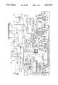
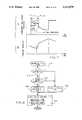
- FIG. 1ais a system diagram of a fluid operated motor vehicle transmission, including several solenoid operated fluid pressure control valves, and a computer-based control unit for carrying out the control technique of this invention.
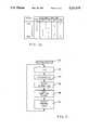
- FIG. 1bis a diagram illustrating the clutch engagements required to establish the various speed ratios of the transmission depicted in FIG. 1a.
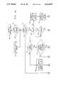
- FIGS. 2 and 3a-3bare flow diagrams representative of computer program instructions executed by the computer-based controller of FIG. 1a in carrying out the shift control of the transmission.
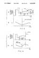
- FIG. 4graphs A, B and C, illustrate on-coming pressure command, off-going pressure command and turbine speed, respectively, for clutch-to-clutch closed throttle downshifting.
- FIG. 5, A and Billustrate the on-coming slip and a turbine speed for the on-coming closed-loop operation.
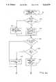
- FIGS. 6a-6b, 8 and 11are flow diagrams illustrating the adaptive clutch control logic for the closed throttle downshift, according to the invention.
- FIGS. 7, 9 and 10are graphs of turbine speed and commanded on-coming clutch pressures for some of the aberrant shift conditions being corrected by the method of the invention.
- the reference numeral 10generally designates a motor vehicle drive train including a throttled internal combustion engine 12, a fluidic torque converter 14, a six-speed fluid operated power transmission 16 and a differential gear set (DG) 18.
- the engine 12is connected to the torque converter 14 via shaft 20
- the torque converter 14is connected to the transmission 16 via shaft 22
- the transmission 16is connected to the differential gear set 18 via shaft 24
- the differential gearsetis connected to a pair of drive wheels (not shown) via the prop shafts 26 and 28.
- Gear shiftsare accomplished by selectively engaging and disengaging brakes and clutches, herein called torque transmitting devices or clutches. These clutches are actuated by hydraulic pressure and upon engagement require a fill time before torque is transmitted between a driving and a driven friction element.
- the speed and torque relationships between the engine 12 and the drive wheels of the vehicleare controlled by a fluid operated torque converter clutch, designated TCC, and five fluid operated transmission clutches, designated C1-C5.
- the torque converter clutch TCCis selectively engaged by the solenoid operated control valve 30 to mechanically connect the impeller I and turbine T of torque converter 14.
- the clutches TCC, C1, C2, C3, C4, C5are selectively engaged and disengaged by the solenoid operated control valves 30, 32, 34, 36, 38, 40 according to the diagram shown in FIG. 1b, to selectively establish a desired transmission speed ratio.
- the illustrated transmission gear setprovides one reverse ratio and six forward ratios, and is described in detail in the U.S. Pat. No. 4,070,927 to Polak, issued Jan. 31, 1978, and assigned to the assignee of the present invention.
- An operator manipulated accelerator pedal 41positions the engine throttle for controlling the engine power output.
- the operation of the solenoid operated control valves 30-40is controlled by a computer-based control unit 42 via lines 44-54 in response to various input signals representative of system parameters.
- Such inputsinclude an engine throttle position signal %T on line 56, an engine output shaft speed signal Ne on line 58, a torque converter output shaft speed signal Nt on line 60, a transmission output shaft speed signal No on line 62, a system supply voltage signal Vb on line 64, a transmission fluid temperature signal Tsump on line 66 and an operator range selector position signal RS on line 68.
- the system voltageis supplied by the storage battery 70, and the input signals are obtained with conventional electrical transducers such as potentiometers, thermistors and magnetic speed pickups.
- control unit 42comprises a number of conventional devices including a microcomputer (uC) with internal clock and memory, an input/output device (I/O) and an array of PWM generators (PWM) and drivers (DR).
- a PWM generator and a driver (DR)are dedicated to each solenoid control valve 30-40.
- the PWM outputsare delivered to the respective drivers (DR) and are used to energize the respective solenoid control valves.
- the duty cycle of the PWM outputsdetermine the hydraulic pressure supplied by the solenoid control valves, with a low percent duty cycle yielding a low pressure and a high percent duty cycle yielding a high pressure for a normally closed valve.
- the hydraulic circuit of transmission 16includes a positive displacement pump 82 for supplying pressurized hydraulic fluid from the sump or reservoir 84, to the clutches TCC and C1-C5 through various hydraulic and electro-hydraulic valving mechanisms. After passing through a main circuit filter 86, the fluid output of pump 82 is directed to a main pressure regulator valve 88 which develops regulated fluid pressures in lines 90 and 92.
- the fluid in line 90is directed through the torque converter 14, as schematically designated by the converter shell 97.
- the converter fluidis then regulated down to a lower pressure by the regulator valve 104 and directed to the transmission lube circuit, as designated by the bubble 106.
- the fluid in line 92is supplied as an input to the clutch control valves 30-40, and also to the control pressure regulator valve 96.
- the control pressure regulator valve 96develops a somewhat lower pressure in line 98, referred to herein as the control pressure, such pressure being directed to the solenoid of each control valve 30-40.
- the fluid in line 94referred to as the converter clutch pressure, is supplied directly by solenoid 30 to the torque converter clutch TCC to engage the same. This pressure is also supplied to the main regulator valve 88 to provide a lower regulated line pressure in the converter lockup mode.
- FIGS. 2, 3a-3b, 6a-6b, 8 and 11are flow diagrams representative of computer program instructions executed by the computer-based control unit 42 of FIG. 1 in carrying out the shift control technique of this invention.
- the functional explanation marked with numerals in angle brackets, ⁇ nn>,refers to blocks bearing that number.
- FIG. 2represents an executive or main loop program which directs the sequential execution of various subroutines.
- Block 130designates a series of instructions executed at the initiation of each period of vehicle operation for setting the various timers, registers and variable values of control unit 42 to predetermined initial values. Thereafter, the blocks 132-140 are sequentially and repeatedly executed as indicated by the flow diagram lines
- Block 132reads the various input signal values and outputs the required control signals to the PWM generators and drivers for solenoid controlled valves 30-40.
- Blocks 134-138contain diagnostic, shift scheduling, and adaptive flag logic.
- the clutch control logic block 140analyzes the various system input signals described above in reference to FIG.
- Block 140also effects pulse-width-modulation of the solenoid drive voltage to carry out the pressure commands for specific shift operations. Block 140 is detailed in the flow chart of FIGS. 3a-3b.
- the flow diagram of FIGS. 3a-3bsets forth the program for making decisions as to the type of range shift in progress, if any, and determines the specific control for the on-coming and the off-going clutches.
- the programalso checks whether a shift has performed within specifications. If not, certain shift parameters are changed at shift completion according to predefined adaptive logic to correct the shift. First, lockup clutch control is executed ⁇ 142> if a lockup shift is in progress ⁇ 144>, and it is then determined (from the shift schedule) whether a range shift is in progress ⁇ 146>. If not, the clutch control logic is exited.
- a range shiftis in progress ⁇ 146>, it is determined whether it is an upshift ⁇ 150>, a downshift ⁇ 152>, or a neutral shift ⁇ 154>. If it is none of these, it must be a garage shift ⁇ 156> which executes shifts from neutral to either drive or reverse and shifts from drive to reverse or from reverse to drive. If it is a neutral shift ⁇ 154>, the neutral shift clutch control executes shifts from drive to neutral or from reverse to neutral ⁇ 155>. The control flows from either the upshift, downshift, neutral shift or the garage shift block to the end-of-shift test ⁇ 160>.
- an upshiftis indicated ⁇ 150>
- the upshift on-coming clutch control ⁇ 164> and the upshift off-going clutch control ⁇ 166>are activated.
- a downshiftis indicated ⁇ 152>
- the powered downshift on-coming clutch controlis activated ⁇ 174> and then the powered downshift off-going clutch control is activated ⁇ 176>. If it is determined at block 173 that the CLOSED THROTTLE flag is set, the throttle opened during the course of the closed throttle downshift and a transition to powered downshift may be necessary; in this case, the transition logic is invoked ⁇ 178>. Finally, the program goes to the end of shift test ⁇ 160>.
- Each control phaseoperates by setting pressures, pressure increments, times or other values to predefined calibrated values which are herein generally called “set”, “preset”, “given” or “certain” values.
- setis chosen from a table of calibrated values for each specific transmission condition, throttle range and shift type.
- different valuesare supplied for upshift, downshift, etc., as well as each range shift, e.g., 1-2, 2-1, 4-3, 5-4, etc.
- Converter and lockup modesmay also require separate sets of calibration values.
- FIG. 4graphs A, B and C, respectively, show the on-coming and off-going pressure commands for control of the on-coming and off-going clutches during a closed throttle downshift and the turbine speed Nt.
- the on-coming pressure commandis set to maximum for a fill time to prepare the on-coming clutch to accept torque.
- the off-going clutch pressure commandis stepped to an intermediate value Pint for a set time and is then stepped to a lower value Pioff until a preset time before the end of the fill time.
- the fill time less the preset timedetermines the off-going clutch period. Then the off-going clutch is exhausted so that the on-coming clutch can take over when it is ready.
- the on-coming clutch pressure commandis set to an initial pressure, Pion, and then ramped up until slip of the off-going clutch (or turbine pullup) is detected.
- Turbine pullupis a result of the beginning of off-going clutch slip. Pullup is detected by the turbine speed Nt becoming greater than the product of the output speed No and the old or lower speed ratio SR(old) plus a constant K1 or Nt>No * SR(old)+K1.
- the off-going clutch sliptriggers closed-loop control of the on-coming clutch pressure.
- the initial closed-loop pressureis Picl.
- the on-coming clutch slipis monitored and controlled to a calculated slip profile. This closed-loop slip profile control continues until on-coming clutch synchronization has been detected for several consecutive times. Synchronization is detected when the turbine speed is within a threshold value, K2, of the output speed times the new or high speed ratio, or ABS(Nt-No * SR(new)) ⁇ K2.
- K2threshold value
- graph Awhich shows the on-coming slip speed profile in solid lines and actual slip speed in dashed lines.
- the initial slip speed, SLIPIis the absolute slip speed value at the initiation of closed-loop.
- the slip profilebegins at that point and decreases at a fixed rate, called the first slope.
- the ratereduces to a second slope.
- the slopesare chosen so that, ideally, the actual slip speed can be made to smoothly go to zero within a given time period.
- the second slopeis less steep than the first slope and reduces end of shift torque disturbance by more closely matching the acceleration rates on both sides of the on-coming clutch.
- the constant C1is a fraction of SLIPI at which the second slope begins; i.e., if SLIP ⁇ C1*SLIPI, the slope changes to the second slope.
- the constant C2is the desired time to utilize the first slope.
- the constant C3is the desired overall closed-loop time.
- the constants C2 and C3are used only for slope calculations and not for direct timing purposes.
- Proportional controlis carried out by correcting the on-coming clutch command pressure by a term which is proportional to slip speed error.
- the effect on turbine speedis shown in FIG. 5, graph B, where pullup is detected when turbine speed increases a certain amount above the lower dashed line which represents the product of output speed and speed ratio for the old range. Thereafter the turbine speed increases in accordance with the profile control where on-coming clutch slip is seen to be the difference (times a conversion factor) between the turbine speed curve and the upper dashed line, which represents the product of output speed and speed ratio for the new range.
- the arrival at synchronization speedis determined by detecting synchronization (sync) a preset number of times in consecutive-loops. This signals completion of the closed-loop profile control, and maximum pressure is applied to the on-coming clutch.
- the controlhas several advantages.
- the initial off-going pressure intermediate value Pintreduces clutch pressure undershoot caused by solenoid dynamics.
- the lower off-going pressure Pioffis sufficient to maintain the old range and allows transition to off-going clutch control in the event of a throttle increase before the off-going clutch is exhausted. By exhausting the off-going clutch before the end of fill time it is assured that off-going clutch capacity is removed before application of the on-coming clutch and thereby eliminates clutch tie-up and associated shift quality degradation.
- the off-going clutch slipis used to detect turbine pullup and thereby indicate that on-coming clutch capacity has been achieved. This automatically times the application of closed-loop control.
- the on-coming pressure commandis ramped up following fill termination to achieve a timely turbine pullup when the initial on-coming command pressure is low. If the off-going clutch slip is detected during the fill period, the fill period is terminated early to reduce the overfill torque disturbance.
- the closed-loop profilecontrols the on-coming clutch slip (rather than turbine speed) to insure that changes in output speed (due to braking) are also taken into account when controlling shift duration.
- the reduced slopeafter a specified fraction of the initial on-coming clutch slip is achieved, reduces end of shift torque disturbance by more closely matching the acceleration rates on both sides of the on-coming clutch. Maintaining closed-loop control until sync has been detected in several consecutive control-loops assures that true sync has been achieved and maintained before full clutch application is made.
- Adaptive controladjusts certain parameters for each type of shift independently of other types. That is, a 2-1 closed throttle downshift is treated separately from a 4-3 closed throttle downshift, and the shift quality of each is separately monitored and the parameters for each type are individually adjusted and stored. The process of adapting the parameters for a particular type of shift is on-going and proceeds during each shift of that type independently of the other types of shifts.
- the block 162sets adaptive conditions. This is accomplished in three phases: diagnosing the shift to identify input and/or output speed aberrations, determining whether fast or slow adaptive adjustment is permitted, and calculating new parameter values for the next shift. If fast adaptive adjustment (fast adapt) is permitted, a parameter value is calculated which is generally targeted to fully correct the aberration in the next shift. If slow adaptive adjustment (slow adapt) is required, the existing parameter is changed by a set increment.
- the systemis capable of being programmed to make a partial correction in the fast adaptive mode and this is sometimes employed to avoid a possible "over correction".
- fast and slow adaptive adjustmentis based on the need to make potentially large adjustments when a new or rebuilt transmission is initially operated in a given vehicle/engine combination as opposed to the need to make small updates due to clutch plate wear, engine performance degradation, oil viscosity degradation and the like during the life of the transmission.
- the electronic controlis set to make fast adaptive adjustments for each type of shift.
- the shift calibrationis said to be "converged" to an optimal solution and a memory flag is set to control future shifts of that type to the slow adaptive mode. Once the control enters the slow mode, it is assured that a misleading speed signal caused by system noises can not trigger a large adjustment when little, if any, adjustment is appropriate.
- the diagnosis of shift aberrationsis accomplished by monitoring key shift quality indicators during the shift and setting a memory flag whenever a certain speed change occurs under given conditions, a certain change of command pressure takes place, or certain corrective action has already been taken.
- the shift pattern of the transmissionis embodied in these indicators. Then by a logical assessment of the states of the several flags the presence of a given aberration is determined and a suitable adjustment can then be calculated.
- SLIP EARLYOff-going clutch slip is detected within a set time window from the end of the fill period for a given number of times.
- Underlapis detected before the end of the fill period. Underlap is the condition when Nt ⁇ No*SR(old)+Ku occurs for a number of consecutive control loops where Ku is a negative calibration constant.
- CLOSED-LOOP INCREASE(CLI): A closed-loop increase occurs when the commanded on-coming pressure at the first detected sync exceeds the initial closed-loop pressure command by a threshold amount.
- CLOSED-LOOP DECREASEA closed-loop decrease occurs when the commanded on-coming pressure at the first detected sync is below the initial closed-loop pressure command by a threshold amount.
- HI DECELHigh output deceleration occurs when acceleration is less than a given amount at shift initiation.
- HI TURBINE ACCELFollowing detection of off-going clutch slip, turbine acceleration is greater than a given amount for a set number of control loops.
- SHORT SHIFTTime from first slip of the off-going clutch to first sync is less than a set amount.
- LONG SHIFTTime from first slip of the off-going clutch to first sync is greater than a set amount.
- SHORT CLOSED-LOOPTime from first slip to first sync is less than a set amount (different from the set amount for the SHORT SHIFT).
- PULL-DOWN LATEIf turbine flare is present, then the time to maximum turbine speed is greater than the fill time by a set amount. Flare is defined as Nt>No*SR(new)+K.
- FILL TIME DECREASEDA memory flag which indicates that the fill time has been decreased within a calibration number of shifts.
- FAST ADAPT OVERFILLSA memory flag which indicates that corrections to overfills will use the fast adaptive calculation.
- SHIFT CONVERGEDA memory flag which indicates that the shift calibration has converged to an optimal solution.
- the adaptive control for the closed throttle downshiftadjusts the stored parameters corresponding to fill time, Tfill, initial on-coming pressure command, Pion, and off-going pressure command, Pioff.
- pressure adjustments K2are made to Pion and Pioff, and a time adjustment K1 is made to Tfill.
- the fast adaptive modecalculations are used to determine the amount of adjustment to decrease fill time, Tfill, and to adjust the initial on-coming pressure command Pion.
- FIGS. 6a-6bshows the progress of the adaptive closed throttle downshift program in block 162. If the shift cycle counter (SCC) is zero ⁇ 200>, the FILL TIME DECREASED flag is reset ⁇ 202>. If SCC is not zero ⁇ 200>, it is decremented ⁇ 204>. If the HIGH OUTPUT DECEL flag is set ⁇ 206>, the adaptive program exits to the main program. This is done because sudden deceleration (such as caused by hard braking) can distort the speed signals and cause false flags to be set. If the HI OUTPUT DECEL flag is not set, the SLIP EARLY flag is tested ⁇ 208>. If the flag is set, it is an indication of overfill of the on-coming clutch. Then the fill time is decreased ⁇ 210> to correct the overfill condition.
- SCCshift cycle counter
- the overfill conditionis illustrated in FIG. 7 which shows the actual pressure becoming large during the fill time causing turbine speed pullup at time Tslip during fill time. This condition sets the SLIP EARLY flag.
- the decrease fill time routineis shown in FIG. 8. If the shift has converged ⁇ 212> or the FAST ADAPT OVERFILLS flag is not set ⁇ 214>, the slow adapt mode is selected and the fill time is decremented by the value K1 ⁇ 216>.
- K5is chosen to be 100%
- the new fill timewill be set to expire the offset time K6 before slip occurs in the off-going clutch as indicated in FIG. 7.
- the Shift Cycle Counteris set to a value K7
- the FILL TIME DECREASED flagis set and the FAST ADAPT OVERFILLS (FAO) flag is set ⁇ 220>.
- the adaptive programis exited.
- the action in block 220assures that the FILL TIME DECREASED flag will remain set until the number K7 of closed throttle downshifts between the same ranges have run.
- the FAO flagis reset or cleared ⁇ 222>.
- the FAO flag logicprevents the targeting of a large decrease in the fill time as a result of a noise disturbance. Initially, the FAO flag is set so that overfills will be adapted using the fast adaptive algorithm. However, once a shift is done where an overfill is not detected through the EARLY SLIP flag ⁇ 208>, then the FAO flag will be reset ⁇ 222>. If a later shift detects an overfill while the FAO flag is clear, then only a small decrease to the fill time will be allowed ⁇ 214, 216>. The FAO flag will then be set ⁇ 220> so that if a second consecutive overfill is detected, the fast adaptive change will be used.
- block 224detects the presence of an underfilled on-coming clutch. If the SLIP LATE flag, the PULL DOWN LATE flag or the UNDERLAP AFTER FILL flag is set, the clutch is diagnosed as underfilled. Blocks 226 and 228 determine whether the cause of underfill is a low fill time Tfill or a low initial on-coming pressure Pion. If the FILL TIME DECREASED flag is set ⁇ 226>, then the fill time does not need to be increased and the on-coming pressure will be increased using the slow mode ⁇ 230>, if there is no closed-loop increase ⁇ 232> or if the shift is converged ⁇ 234>. The fast adaptive algorithm 236 will be used if there is a closed-loop increase ⁇ 232> and the shift is not converged ⁇ 234>.
- the fast adaptive algorithm for on-coming pressureis best described with reference to FIG. 9, graph A, which shows the on-coming pressure experiencing an increase during the closed-loop phase.
- the initial closed-loop pressureis Picl and the final closed-loop pressure is Pfcl.
- a programmed desired pressure increaseis K4.
- the CLOSED-LOOP INCREASE flagis set when Pfcl-Picl exceeds a threshold.
- the full correction Dp of Pionis thus Pfcl-Picl-K4. If a partial correction is desired, a percentage K3 of the full value may be used.
- block 228is used to determine the cause of the underfill. If a CLI (CLOSED-LOOP INCREASE) flag is not set (or is not valid), then the on-coming pressure is assumed to be correct and the fill time is increased ⁇ 238>. If a CLI flag is present and is valid, then the on-coming pressure must be too low and is therefore increased ⁇ 236, 230>. This is illustrated in FIG. 9. In Graph A, the closed-loop phase begins before slip is detected due to a clock timeout from the end of fill. Graph B shows the turbine speed Nt (which is pulled up indicating clutch slip) after the closed loop begins. Thus, the SLIP LATE flag is set and the CLI flag is also set because of the pressure increase. Thus, the initial pressure Pion should be increased to bring about slip shortly after the end of the fill period.
- CLICLOSED-LOOP INCREASE
- the SHORT CLOSED-LOOP flagindicates that the shift was not in closed-loop long enough to ensure that the CLI flag is valid. This could happen when closed-loop is initiated following a timeout condition from the end of fill. This is shown in FIG. 10, Graphs A and B. In this case, closed-loop pressure will begin to increase until slip occurs (i.e. turbine speed is pulled up). The short closed-loop period ends (sync occurs) before the on-coming pressure can decrease to the desired value.
- the SHORT CLOSED-LOOP flagis then used to indicate that the closed-loop increase was not valid. Additionally, the HI TURBINE ACCEL flag indicates that the on-coming pressure is too high, which contradicts a CLI flag. Thus, if either the SHORT CLOSED-LOOP flag or the HI TURBINE ACCEL flag is set, then the fill time is assumed to be the cause of the underfill. If this assumption is incorrect, the increase in fill time will cause an overfill to occur. Thus, after correcting for the overfill, the FILL TIME DECREASED flag will be set and will cause the initial on-coming pressure to be corrected.
- an Adapt Pion routineis entered ⁇ 240>. As shown in FIG. 11, a test is made for high initial on-coming pressure Pion. For all shifts except a 2-1 shift, a SHORT SHIFT flag indicates high Pion ⁇ 242>. A 2-1 shift is a special case because for that shift, the shift time is significantly dependent on output deceleration. High turbine acceleration is used to indicate a high initial on-coming pressure for the 2-1 shift ⁇ 244>. When high Pion is thus determined, Pion is decreased.
- the final test in the adaptive programis for the flag UNDERLAP DURING FILL ⁇ 266>. Underlap is detected by sensing when the turbine speed decreases a given amount below a value corresponding to the product of the output speed and the lower speed ratio. This condition implies that neither clutch is transmitting sufficient torque and the transmission is lapsing into neutral. When this occurs during clutch fill, it is an indication that the initial off-going pressure Pioff is too low. The pressure Pioff is then increased a small amount K2 ⁇ 268>. Then the program returns to the main control program.
Landscapes
- Engineering & Computer Science (AREA)
- General Engineering & Computer Science (AREA)
- Physics & Mathematics (AREA)
- Fluid Mechanics (AREA)
- Mechanical Engineering (AREA)
- Control Of Transmission Device (AREA)
Abstract
Description
Claims (11)
Priority Applications (5)
| Application Number | Priority Date | Filing Date | Title |
|---|---|---|---|
| US07/463,718US5211079A (en) | 1990-01-11 | 1990-01-11 | Method of adaptive control for closed throttle downshift in an automatic transmission |
| CA002026366ACA2026366C (en) | 1990-01-11 | 1990-09-27 | Method of adaptive control for closed throttle downshift in an automatic transmission |
| DE69018418TDE69018418T2 (en) | 1989-12-26 | 1990-12-13 | Process for controlling gear change in automatic transmissions. |
| EP90203332AEP0435377B1 (en) | 1989-12-26 | 1990-12-13 | Method of controlling gear change in an automatic transmission |
| JP2418347AJPH05312258A (en) | 1989-12-26 | 1990-12-26 | How to control changes in a vehicle's automatic transmission |
Applications Claiming Priority (1)
| Application Number | Priority Date | Filing Date | Title |
|---|---|---|---|
| US07/463,718US5211079A (en) | 1990-01-11 | 1990-01-11 | Method of adaptive control for closed throttle downshift in an automatic transmission |
Publications (1)
| Publication Number | Publication Date |
|---|---|
| US5211079Atrue US5211079A (en) | 1993-05-18 |
Family
ID=23841094
Family Applications (1)
| Application Number | Title | Priority Date | Filing Date |
|---|---|---|---|
| US07/463,718Expired - LifetimeUS5211079A (en) | 1989-12-26 | 1990-01-11 | Method of adaptive control for closed throttle downshift in an automatic transmission |
Country Status (2)
| Country | Link |
|---|---|
| US (1) | US5211079A (en) |
| CA (1) | CA2026366C (en) |
Cited By (37)
| Publication number | Priority date | Publication date | Assignee | Title |
|---|---|---|---|---|
| US5282401A (en)* | 1992-02-07 | 1994-02-01 | General Motors Corporation | Adaptive electronic control of power-on upshifting in an automatic transmission |
| US5413539A (en)* | 1992-08-10 | 1995-05-09 | Ford Motor Company | Control system for controlling engagement of an automatic transmission torque converter clutch |
| US5467854A (en)* | 1994-06-07 | 1995-11-21 | Caterpillar Inc. | Method of controlling clutch-to-clutch shifts for a powershift transmission |
| US5505100A (en)* | 1994-09-29 | 1996-04-09 | Caterpillar Inc. | Method of controlling interrupted shifts for a powershift transmission |
| US5518468A (en)* | 1994-06-29 | 1996-05-21 | Ford Motor Company | Compensation for fluid viscosity in automatic transmission friction element engagement |
| US5551930A (en)* | 1995-04-13 | 1996-09-03 | Caterpillar Inc. | Adaptive control method for an automatic transmission |
| US5580332A (en)* | 1995-04-13 | 1996-12-03 | Caterpillar Inc. | Method for determining the fill time of a transmission clutch |
| US5685799A (en)* | 1996-07-01 | 1997-11-11 | General Motors Corporation | Automatic transmission shift stabilization control |
| US5865707A (en)* | 1996-01-08 | 1999-02-02 | Honda Giken Kogyo Kabushiki Kaisha | Shift control method for an automatic transmission based upon slippage rates of engagement elements |
| US5888170A (en)* | 1996-07-31 | 1999-03-30 | Jatco Corporation | Downshift control device for automatic transmission |
| US5950789A (en)* | 1998-04-27 | 1999-09-14 | Caterpillar Inc. | End of fill detector for a fluid actuated clutch |
| US6101438A (en)* | 1995-12-12 | 2000-08-08 | Zf Friedirchshafen Ag | Process for automatically co-ordinating the filling operation of shift elements |
| US6115661A (en)* | 1998-04-09 | 2000-09-05 | Caterpillar Inc. | End-of-fill detector for a fluid actuated clutch |
| US6149548A (en)* | 1999-04-01 | 2000-11-21 | Daimlerchrysler Corporation | Element overlap control for an automatic transmission |
| US6308125B1 (en) | 2000-05-11 | 2001-10-23 | General Motors Corporation | Adaptive clutch control of a closed-throttle downshift |
| US6361474B1 (en) | 2000-05-11 | 2002-03-26 | General Motors Corporation | Closed-throttle downshift clutch control for an automatic transmission |
| US6464617B1 (en)* | 1999-12-10 | 2002-10-15 | Hyundai Motor Company | Shift control method for automatic transmission |
| US6478713B1 (en) | 2000-10-23 | 2002-11-12 | General Motors Corporation | Engine limit control for closed-throttle transmission shifting |
| US20040255654A1 (en)* | 2003-06-23 | 2004-12-23 | Bulgrien Garth H. | Detecting clutch slippage to measure drive line torque for clutch control during power shifts |
| US20050257632A1 (en)* | 2004-05-21 | 2005-11-24 | Runde Jeffrey K | Method of determining initial transmission calibration |
| US20050288153A1 (en)* | 2004-06-14 | 2005-12-29 | Whitton Matthew D | Method and apparatus for adaptive control of closed throttle downshifts in an automatic transmission |
| US20060089775A1 (en)* | 2004-10-22 | 2006-04-27 | Whitton Matthew D | Method and apparatus for adaptive control of power-on downshifts in an automatic transmission |
| US20060270521A1 (en)* | 2005-05-25 | 2006-11-30 | James Steven F | Method for improving a drive-to-park shift |
| US20070010373A1 (en)* | 2005-07-06 | 2007-01-11 | Deere & Company, A Delaware Corporation | Transmission shift control method |
| US20070012538A1 (en)* | 2005-07-15 | 2007-01-18 | Jatco Ltd | Shift control apparatus and method for automatic transmission |
| EP1188967A3 (en)* | 2000-09-18 | 2007-06-27 | JATCO Ltd | Shift control system for automatic transmission |
| US20070276569A1 (en)* | 2006-05-25 | 2007-11-29 | Sah Jy-Jen F | Method and apparatus to control an electro-mechanical transmission during shifting event |
| US20080096721A1 (en)* | 2006-10-24 | 2008-04-24 | Jatco Ltd | Automatic transmission control apparatus |
| US20090209383A1 (en)* | 2008-02-14 | 2009-08-20 | Gm Global Technology Operations, Inc. | Transmission Clutch Control Apparatus And Method |
| US20100228412A1 (en)* | 2009-03-06 | 2010-09-09 | Gm Global Technology Operations, Inc. | Multi-mode hybrid transmission and method for performing a quasi-asynchronous shift in a hybrid transmission |
| US20120065849A1 (en)* | 2010-09-09 | 2012-03-15 | Gm Global Technology Operations, Inc. | System and method for controlling power downshifts of a transmission |
| US20120247611A1 (en)* | 2009-12-18 | 2012-10-04 | Zf Friedrichshafen Ag | Method for quickly filling a hydraulically actuated multiple disc shifting element of a motor vehicle transmission |
| CN103574006A (en)* | 2012-07-19 | 2014-02-12 | 通用汽车环球科技运作有限责任公司 | PID-based torque phase control of power downshift |
| US9919700B2 (en)* | 2014-02-28 | 2018-03-20 | Aisin Aw Co., Ltd. | Vehicle control device |
| CN113531115A (en)* | 2020-04-21 | 2021-10-22 | 现代自动车株式会社 | Clutch control method for vehicle |
| CN114704627A (en)* | 2022-04-25 | 2022-07-05 | 哈尔滨东安汽车发动机制造有限公司 | Self-adaptive control method of automatic transmission |
| CN116181901A (en)* | 2023-02-20 | 2023-05-30 | 西安双特智能传动有限公司 | Hydraulic automatic transmission clutch self-learning control method and device |
Citations (8)
| Publication number | Priority date | Publication date | Assignee | Title |
|---|---|---|---|---|
| US4653350A (en)* | 1985-11-29 | 1987-03-31 | General Motors Corporation | Adaptive direct pressure shift control for a motor vehicle transmission |
| US4698763A (en)* | 1985-03-15 | 1987-10-06 | Eaton Corporation | Automatic mechanical transmission control |
| US4707789A (en)* | 1985-11-29 | 1987-11-17 | General Motors Corporation | Adaptive direct pressure shift control for a motor vehicle transmission |
| US4843922A (en)* | 1987-02-27 | 1989-07-04 | Toyota Jidosha Kabushiki Kaisha | Hydraulic control system for automatic transmission |
| US4870581A (en)* | 1986-08-20 | 1989-09-26 | Aisin-Warner Kabushiki Kaisha | Electronically controlled automatic transmission |
| US4875391A (en)* | 1988-04-29 | 1989-10-24 | Chrysler Motors Corporation | Electronically-controlled, adaptive automatic transmission system |
| US4922425A (en)* | 1986-04-18 | 1990-05-01 | Eaton Corporation | Method for controlling AMT system including throttle position sensor signal fault detection and tolerance |
| US4928557A (en)* | 1987-12-04 | 1990-05-29 | Toyota Jidosha Kabushiki Kaisha | Hydraulic transmission controller with coupling pressure compensation |
- 1990
- 1990-01-11USUS07/463,718patent/US5211079A/ennot_activeExpired - Lifetime
- 1990-09-27CACA002026366Apatent/CA2026366C/ennot_activeExpired - Fee Related
Patent Citations (8)
| Publication number | Priority date | Publication date | Assignee | Title |
|---|---|---|---|---|
| US4698763A (en)* | 1985-03-15 | 1987-10-06 | Eaton Corporation | Automatic mechanical transmission control |
| US4653350A (en)* | 1985-11-29 | 1987-03-31 | General Motors Corporation | Adaptive direct pressure shift control for a motor vehicle transmission |
| US4707789A (en)* | 1985-11-29 | 1987-11-17 | General Motors Corporation | Adaptive direct pressure shift control for a motor vehicle transmission |
| US4922425A (en)* | 1986-04-18 | 1990-05-01 | Eaton Corporation | Method for controlling AMT system including throttle position sensor signal fault detection and tolerance |
| US4870581A (en)* | 1986-08-20 | 1989-09-26 | Aisin-Warner Kabushiki Kaisha | Electronically controlled automatic transmission |
| US4843922A (en)* | 1987-02-27 | 1989-07-04 | Toyota Jidosha Kabushiki Kaisha | Hydraulic control system for automatic transmission |
| US4928557A (en)* | 1987-12-04 | 1990-05-29 | Toyota Jidosha Kabushiki Kaisha | Hydraulic transmission controller with coupling pressure compensation |
| US4875391A (en)* | 1988-04-29 | 1989-10-24 | Chrysler Motors Corporation | Electronically-controlled, adaptive automatic transmission system |
Cited By (52)
| Publication number | Priority date | Publication date | Assignee | Title |
|---|---|---|---|---|
| US5282401A (en)* | 1992-02-07 | 1994-02-01 | General Motors Corporation | Adaptive electronic control of power-on upshifting in an automatic transmission |
| US5413539A (en)* | 1992-08-10 | 1995-05-09 | Ford Motor Company | Control system for controlling engagement of an automatic transmission torque converter clutch |
| US5467854A (en)* | 1994-06-07 | 1995-11-21 | Caterpillar Inc. | Method of controlling clutch-to-clutch shifts for a powershift transmission |
| US5518468A (en)* | 1994-06-29 | 1996-05-21 | Ford Motor Company | Compensation for fluid viscosity in automatic transmission friction element engagement |
| US5505100A (en)* | 1994-09-29 | 1996-04-09 | Caterpillar Inc. | Method of controlling interrupted shifts for a powershift transmission |
| US5580332A (en)* | 1995-04-13 | 1996-12-03 | Caterpillar Inc. | Method for determining the fill time of a transmission clutch |
| US5551930A (en)* | 1995-04-13 | 1996-09-03 | Caterpillar Inc. | Adaptive control method for an automatic transmission |
| US6101438A (en)* | 1995-12-12 | 2000-08-08 | Zf Friedirchshafen Ag | Process for automatically co-ordinating the filling operation of shift elements |
| US5865707A (en)* | 1996-01-08 | 1999-02-02 | Honda Giken Kogyo Kabushiki Kaisha | Shift control method for an automatic transmission based upon slippage rates of engagement elements |
| US5685799A (en)* | 1996-07-01 | 1997-11-11 | General Motors Corporation | Automatic transmission shift stabilization control |
| US5888170A (en)* | 1996-07-31 | 1999-03-30 | Jatco Corporation | Downshift control device for automatic transmission |
| US6115661A (en)* | 1998-04-09 | 2000-09-05 | Caterpillar Inc. | End-of-fill detector for a fluid actuated clutch |
| US5950789A (en)* | 1998-04-27 | 1999-09-14 | Caterpillar Inc. | End of fill detector for a fluid actuated clutch |
| US6149548A (en)* | 1999-04-01 | 2000-11-21 | Daimlerchrysler Corporation | Element overlap control for an automatic transmission |
| US6464617B1 (en)* | 1999-12-10 | 2002-10-15 | Hyundai Motor Company | Shift control method for automatic transmission |
| US6308125B1 (en) | 2000-05-11 | 2001-10-23 | General Motors Corporation | Adaptive clutch control of a closed-throttle downshift |
| US6361474B1 (en) | 2000-05-11 | 2002-03-26 | General Motors Corporation | Closed-throttle downshift clutch control for an automatic transmission |
| EP1188967A3 (en)* | 2000-09-18 | 2007-06-27 | JATCO Ltd | Shift control system for automatic transmission |
| US6478713B1 (en) | 2000-10-23 | 2002-11-12 | General Motors Corporation | Engine limit control for closed-throttle transmission shifting |
| US20040255654A1 (en)* | 2003-06-23 | 2004-12-23 | Bulgrien Garth H. | Detecting clutch slippage to measure drive line torque for clutch control during power shifts |
| US6880393B2 (en)* | 2003-06-23 | 2005-04-19 | Cnh America Llc | Detecting clutch slippage to measure drive line torque for clutch control during power shifts |
| US20050257632A1 (en)* | 2004-05-21 | 2005-11-24 | Runde Jeffrey K | Method of determining initial transmission calibration |
| US7069767B2 (en)* | 2004-05-21 | 2006-07-04 | General Motors Corporation | Method of determining initial transmission calibration |
| US20050288153A1 (en)* | 2004-06-14 | 2005-12-29 | Whitton Matthew D | Method and apparatus for adaptive control of closed throttle downshifts in an automatic transmission |
| US7374513B2 (en)* | 2004-06-14 | 2008-05-20 | General Motors Corporation | Method and apparatus for adaptive control of closed throttle downshifts in an automatic transmission |
| US20060089775A1 (en)* | 2004-10-22 | 2006-04-27 | Whitton Matthew D | Method and apparatus for adaptive control of power-on downshifts in an automatic transmission |
| US20060270521A1 (en)* | 2005-05-25 | 2006-11-30 | James Steven F | Method for improving a drive-to-park shift |
| US7311639B2 (en) | 2005-05-25 | 2007-12-25 | General Motors Corporation | Method for improving a drive-to-park shift |
| US20070010373A1 (en)* | 2005-07-06 | 2007-01-11 | Deere & Company, A Delaware Corporation | Transmission shift control method |
| US7278953B2 (en)* | 2005-07-06 | 2007-10-09 | Deere & Company | Transmission shift control method |
| US20070012538A1 (en)* | 2005-07-15 | 2007-01-18 | Jatco Ltd | Shift control apparatus and method for automatic transmission |
| US7500932B2 (en)* | 2005-07-15 | 2009-03-10 | Jatco Ltd | Shift control apparatus and method for automatic transmission |
| US7706949B2 (en)* | 2006-05-25 | 2010-04-27 | Gm Global Technology Operations, Inc. | Method and apparatus to control an electro-mechanical transmission during shifting event |
| US20070276569A1 (en)* | 2006-05-25 | 2007-11-29 | Sah Jy-Jen F | Method and apparatus to control an electro-mechanical transmission during shifting event |
| US20080096721A1 (en)* | 2006-10-24 | 2008-04-24 | Jatco Ltd | Automatic transmission control apparatus |
| US7912614B2 (en)* | 2006-10-24 | 2011-03-22 | Jatco Ltd | Automatic transmission control apparatus |
| US20090209383A1 (en)* | 2008-02-14 | 2009-08-20 | Gm Global Technology Operations, Inc. | Transmission Clutch Control Apparatus And Method |
| US8364361B2 (en)* | 2008-02-14 | 2013-01-29 | GM Global Technology Operations LLC | Transmission clutch control apparatus and method |
| US8412426B2 (en) | 2009-03-06 | 2013-04-02 | GM Global Technology Operations LLC | Multi-mode hybrid transmission and method for performing a quasi-asynchronous shift in a hybrid transmission |
| US20100228412A1 (en)* | 2009-03-06 | 2010-09-09 | Gm Global Technology Operations, Inc. | Multi-mode hybrid transmission and method for performing a quasi-asynchronous shift in a hybrid transmission |
| US8726751B2 (en)* | 2009-12-18 | 2014-05-20 | Zf Friedrichshafen Ag | Method for quickly filling a hydraulically actuated multiple disc shifting element of a motor vehicle transmission |
| US20120247611A1 (en)* | 2009-12-18 | 2012-10-04 | Zf Friedrichshafen Ag | Method for quickly filling a hydraulically actuated multiple disc shifting element of a motor vehicle transmission |
| CN102434659A (en)* | 2010-09-09 | 2012-05-02 | 通用汽车环球科技运作有限责任公司 | System and method for controlling power downshifts of a transmission |
| US8688336B2 (en)* | 2010-09-09 | 2014-04-01 | GM Global Technology Operations LLC | System and method for controlling power downshifts of a transmission |
| US20120065849A1 (en)* | 2010-09-09 | 2012-03-15 | Gm Global Technology Operations, Inc. | System and method for controlling power downshifts of a transmission |
| CN103574006A (en)* | 2012-07-19 | 2014-02-12 | 通用汽车环球科技运作有限责任公司 | PID-based torque phase control of power downshift |
| CN103574006B (en)* | 2012-07-19 | 2016-05-11 | 通用汽车环球科技运作有限责任公司 | The moment of torsion stage control that power based on PID lowers category |
| US9919700B2 (en)* | 2014-02-28 | 2018-03-20 | Aisin Aw Co., Ltd. | Vehicle control device |
| CN113531115A (en)* | 2020-04-21 | 2021-10-22 | 现代自动车株式会社 | Clutch control method for vehicle |
| CN114704627A (en)* | 2022-04-25 | 2022-07-05 | 哈尔滨东安汽车发动机制造有限公司 | Self-adaptive control method of automatic transmission |
| CN114704627B (en)* | 2022-04-25 | 2023-05-05 | 哈尔滨东安汽车发动机制造有限公司 | Self-adaptive control method for automatic transmission |
| CN116181901A (en)* | 2023-02-20 | 2023-05-30 | 西安双特智能传动有限公司 | Hydraulic automatic transmission clutch self-learning control method and device |
Also Published As
| Publication number | Publication date |
|---|---|
| CA2026366A1 (en) | 1991-07-12 |
| CA2026366C (en) | 1994-05-31 |
Similar Documents
| Publication | Publication Date | Title |
|---|---|---|
| US5211079A (en) | Method of adaptive control for closed throttle downshift in an automatic transmission | |
| US5072390A (en) | Adaptive control of an automatic transmission | |
| US5046174A (en) | Method of clutch-to-clutch closed throttle downshift in an automatic transmission | |
| US5070747A (en) | Adaptive powered downshift control of an automatic transmission | |
| EP0435373B1 (en) | Method of controlling gear changes in an automatic transmission | |
| US5058460A (en) | Clutch-to-clutch control in an automatic transmission | |
| US5046175A (en) | Method of detecting clutch tie-up during transmission shifting | |
| US5014573A (en) | Double transition upshift control in an automatic transmission | |
| EP0436978B1 (en) | Method of controlling gear changes in an automatic transmission | |
| US4989477A (en) | Double transition closed throttle downshift control in an automatic transmissions | |
| US5113343A (en) | Sequenced control of double transition powered downshifting in an automatic transmission | |
| US5216606A (en) | Compensated control method for filling a fluid-operated automatic transmission clutch | |
| US5551930A (en) | Adaptive control method for an automatic transmission | |
| US7559876B2 (en) | Method of detecting and preventing tie-up during a double transition up-shift | |
| EP0435377B1 (en) | Method of controlling gear change in an automatic transmission | |
| US5343782A (en) | Anti-flare method using offgoing slip speed and rate of change of slip-speed to determine pressure compensation for incoming clutch | |
| US20050288153A1 (en) | Method and apparatus for adaptive control of closed throttle downshifts in an automatic transmission | |
| EP0435372B1 (en) | Method of controlling gear change in an automatic transmission | |
| EP0435375B1 (en) | Method and apparatus for determining transmission clutch and brake fill time | |
| EP0435376B1 (en) | Method of controlling gear change in an automatic transmission |
Legal Events
| Date | Code | Title | Description |
|---|---|---|---|
| AS | Assignment | Owner name:GENERAL MOTORS CORPORATION, MICHIGAN Free format text:ASSIGNMENT OF ASSIGNORS INTEREST.;ASSIGNORS:RUNDE, JEFFREY K.;HIBNER, JOHN A.;HUNTER, JOSEPH H.;REEL/FRAME:005215/0937;SIGNING DATES FROM 19891213 TO 19891227 | |
| STCF | Information on status: patent grant | Free format text:PATENTED CASE | |
| FPAY | Fee payment | Year of fee payment:4 | |
| FPAY | Fee payment | Year of fee payment:8 | |
| FPAY | Fee payment | Year of fee payment:12 | |
| AS | Assignment | Owner name:GM GLOBAL TECHNOLOGY OPERATIONS, INC., MICHIGAN Free format text:ASSIGNMENT OF ASSIGNORS INTEREST;ASSIGNOR:GENERAL MOTORS CORPORATION;REEL/FRAME:022117/0022 Effective date:20050119 Owner name:GM GLOBAL TECHNOLOGY OPERATIONS, INC.,MICHIGAN Free format text:ASSIGNMENT OF ASSIGNORS INTEREST;ASSIGNOR:GENERAL MOTORS CORPORATION;REEL/FRAME:022117/0022 Effective date:20050119 | |
| AS | Assignment | Owner name:UNITED STATES DEPARTMENT OF THE TREASURY, DISTRICT Free format text:SECURITY AGREEMENT;ASSIGNOR:GM GLOBAL TECHNOLOGY OPERATIONS, INC.;REEL/FRAME:022201/0501 Effective date:20081231 | |
| AS | Assignment | Owner name:CITICORP USA, INC. AS AGENT FOR HEDGE PRIORITY SEC Free format text:SECURITY AGREEMENT;ASSIGNOR:GM GLOBAL TECHNOLOGY OPERATIONS, INC.;REEL/FRAME:022556/0013 Effective date:20090409 Owner name:CITICORP USA, INC. AS AGENT FOR BANK PRIORITY SECU Free format text:SECURITY AGREEMENT;ASSIGNOR:GM GLOBAL TECHNOLOGY OPERATIONS, INC.;REEL/FRAME:022556/0013 Effective date:20090409 | |
| AS | Assignment | Owner name:GM GLOBAL TECHNOLOGY OPERATIONS, INC., MICHIGAN Free format text:RELEASE BY SECURED PARTY;ASSIGNOR:UNITED STATES DEPARTMENT OF THE TREASURY;REEL/FRAME:023238/0015 Effective date:20090709 | |
| XAS | Not any more in us assignment database | Free format text:RELEASE BY SECURED PARTY;ASSIGNOR:UNITED STATES DEPARTMENT OF THE TREASURY;REEL/FRAME:023124/0383 | |
| AS | Assignment | Owner name:GM GLOBAL TECHNOLOGY OPERATIONS, INC., MICHIGAN Free format text:RELEASE BY SECURED PARTY;ASSIGNORS:CITICORP USA, INC. AS AGENT FOR BANK PRIORITY SECURED PARTIES;CITICORP USA, INC. AS AGENT FOR HEDGE PRIORITY SECURED PARTIES;REEL/FRAME:023127/0326 Effective date:20090814 | |
| AS | Assignment | Owner name:UNITED STATES DEPARTMENT OF THE TREASURY, DISTRICT Free format text:SECURITY AGREEMENT;ASSIGNOR:GM GLOBAL TECHNOLOGY OPERATIONS, INC.;REEL/FRAME:023155/0922 Effective date:20090710 | |
| AS | Assignment | Owner name:UAW RETIREE MEDICAL BENEFITS TRUST, MICHIGAN Free format text:SECURITY AGREEMENT;ASSIGNOR:GM GLOBAL TECHNOLOGY OPERATIONS, INC.;REEL/FRAME:023161/0864 Effective date:20090710 |