US5209767A - Glass sheet annealing lehr having gas support conveyor - Google Patents
Glass sheet annealing lehr having gas support conveyorDownload PDFInfo
- Publication number
- US5209767A US5209767AUS07/671,505US67150591AUS5209767AUS 5209767 AUS5209767 AUS 5209767AUS 67150591 AUS67150591 AUS 67150591AUS 5209767 AUS5209767 AUS 5209767A
- Authority
- US
- United States
- Prior art keywords
- gas
- glass sheet
- strip
- sheet strip
- manifold
- Prior art date
- Legal status (The legal status is an assumption and is not a legal conclusion. Google has not performed a legal analysis and makes no representation as to the accuracy of the status listed.)
- Expired - Lifetime
Links
Images


Classifications
- C—CHEMISTRY; METALLURGY
- C03—GLASS; MINERAL OR SLAG WOOL
- C03B—MANUFACTURE, SHAPING, OR SUPPLEMENTARY PROCESSES
- C03B25/00—Annealing glass products
- C03B25/04—Annealing glass products in a continuous way
- C03B25/06—Annealing glass products in a continuous way with horizontal displacement of the glass products
- C03B25/08—Annealing glass products in a continuous way with horizontal displacement of the glass products of glass sheets
- C03B25/093—Annealing glass products in a continuous way with horizontal displacement of the glass products of glass sheets being in a horizontal position on a fluid support, e.g. a gas or molten metal
Definitions
- This inventionrelates to an annealing lehr for annealing a glass sheet strip.
- Glass sheetsare conventionally made by forming a continuous glass sheet strip that is slowly cooled in an annealing lehr to provide annealing so as not to generate internal stresses that are so great as to prevent the strip from subsequently being cut into sheets of a discrete length.
- Conventional processingforms the glass sheet while floating on a molten metal bath of tin and then delivers the glass sheet from the tin bath to the annealing lehr for the slow cooling.
- the lateral edge portions of the glass sheetPrior to entering the annealing lehr, the lateral edge portions of the glass sheet can be trimmed in a hot condition as disclosed by U.S. Pat. No. 4,749,400 Mouly et al.
- the temperature of the glass sheet stripis slowly cooled from the "annealing point" which is normally in the range of about 1000° to 1040° Fahrenheit (about 495° to 560° centigrade) to the strain point which is generally in the range of about 925° to 970° Fahrenheit (about 495° to 520° centigrade). Between 925 ° and 1040° Fahrenheit (540° to 560° centigrade) is conventionally referred to as the "annealing range”.
- both the annealing point and the strain point between which the annealing range extendsare defined as temperatures that correspond either to a specific rate of elongation of a glass fiber when measured by ASTM Method C336 or a specific rate of midpoint deflection of a glass beam when measured by ASTM Method C598.
- Internal stresses of a glass sheet at the annealing pointare substantially relieved in minutes, while internal stresses at the strain point are substantially relieved in hours.
- the continuous glass sheet stripis supported on conveyor rolls for conveyance from the annealing point to the strain point through the annealing range. Since the glass is relatively soft at the annealing point, its surfaces can be deformed by engagement with the conveyor rolls and thereby adversely affect optical quality and mechanical strength.
- An object of the present inventionis to provide an improved annealing lehr for annealing a hot glass sheet strip without engaging the strip during slow cooling during the annealing range so as to provide good optical quality and mechanical strength to the annealed glass.
- a glass sheet strip annealing lehr constructed in accordance with the present inventionincludes a housing defining a heated chamber and having an entry end for receiving a continuous hot glass sheet strip just after forming of the strip prior to cooling below the annealing point.
- the housingalso has an exit end from which the strip exits the heated chamber.
- the heated chamberhas a decreasing temperature from the entry end of the housing toward the exit end thereof to provide relatively slow cooling that anneals the strip.
- a conveyor of the annealing lehrincludes a gas support that delivers upwardly directed pressurized gas to provide the sole support of the glass sheet strip within the housing until the surfaces of the strip are cooled below the strain point.
- the conveyoralso includes a drive for engaging the strip after the surfaces thereof are cooled below the strain point to pull the strip from the entry end of the housing toward the exit end thereof over the gas support.
- the gas support of the conveyorprovides the sole support for the glass sheet strip until the surfaces of the strip are placed in compression by the cooling which normally takes place as the center of the continuous glass sheet strip begins to cool at a faster rate than the surfaces as the glass approaches ambient temperature.
- the preferred construction of the glass sheet strip annealing lehrhas the gas support of the conveyor constructed to include a lower manifold to which the pressurized gas is fed for upward flow that impinges with the glass sheet strip to provide the support of the strip, and the gas support of the conveyor also includes an upper manifold to which gas is fed for downward flow that impinges with the glass sheet strip to cooperate with the upward gas flow in providing uniform forced convection heat transfer with the lower and upper surfaces of the strip.
- Each of the lower and upper manifoldsincludes supply openings through which the pressurized gas is fed for impingement with the glass sheet strip, and each manifold also includes exhaust openings through which the gas is exhausted after impingement with the glass sheet strip.
- Each manifoldhas the supply and exhaust openings thereof provided with elongated shapes that extend transversely to the direction of movement of the glass sheet strip. These supply and exhaust openings of each manifold are in an alternating relationship along the direction of movement of the glass sheet strip.
- each manifoldis construction with each elongated exhaust opening having opposite ends and a central portion between the opposite ends and with the opposite ends of each exhaust opening having a progressively increasing flow area in a direction toward the central portion thereof to prevent a gas pressure buildup at the center of the strip.
- Both of the preferred embodimentshave the supply openings thereof inclined so as to provide driving of the glass sheet strip by the pressurized gas flow toward the exit end of the housing.
- the conveyorpreferably includes a plurality of sets of the lower and upper manifolds that provide the forced convection cooling of the glass sheet strip.
- each manifold of the annealing lehris molded from refractory material and preferably includes a cast platen having a surface that defines the supply and exhaust openings which have elongated shapes that extend transversely to the direction of movement of the glass sheet strip and are arranged in an alternating relationship with respect to each other.
- Each manifoldalso includes a cast manifold member that feeds the pressurized gas to the supply openings of the platen and receives the gas from the exhaust openings of the platen for recirculating flow back to the supply openings.
- Each manifoldpreferably further includes a gas burner and at least one gas jet pump mounted by the manifold member to receive pressurized and heated products of combustion from the gas burner for mixing with the gas returned from the exhaust openings for recirculating flow back to the supply openings.
- the manifold memberincludes two pairs of spaced side walls with each pair of spaced side walls defining a return passage for receiving gas from the exhaust openings of the platen.
- a plurality of the gas jet pumpsare mounted on each pair of side walls and function to mix the pressurized and heated products of combustion received from the gas burner with the gas returned from the exhaust openings of the platen for the recirculating flow back to the supply openings of the platen.
- the two pairs of spaced side wallsare spaced from each other to define a mixing plenum in which the pressurized gas is received from opposite directions from the gas jet pumps for mixing prior to being fed to the supply openings of the platen.
- Each manifold member of the refractory embodiment of the manifoldalso preferably includes temperature controllers for controlling the temperature of the pressurized gas delivered from the mixing plenum to the supply openings of the platen.
- These temperature controllerseach include an electric resistance element to which a voltage is applied as needed to provide the proper degree of additional heating for heating the gas that provides the forced convection heating upon being delivered to the supply openings of the platen.
- Each manifold member of the refractory embodiment of the manifoldalso includes vertical walls spaced along the direction of movement of the glass sheet strip to divide the mixing plenum with one temperature controller and a pair of oppositely directed gas jet pumps located between each pair of vertical walls.
- the pair of oppositely directed gas jet pumps that feed pressurized gas between each pair of vertical walls of the manifold memberare located at different elevations to provide a circular mixing flow. This circular mixing flow takes place away from the temperature controller with respect to the plane of strip conveyance at a location between the two vertical walls involved.
- each manifoldis fabricated from sheet metal as opposed to being molded from factory material.
- the conveyor drive of the annealing lehr as disclosedincludes a roller that engages the lower surface of the glass sheet strip to pull the strip from the entry end of the housing toward the exit end thereof over the gas support.
- the roller of the drivepulls the glass sheet strip between the lower and upper manifolds of the gas support whose forced convection with the lower and upper surfaces provides the slow cooling of the strip for the annealing.
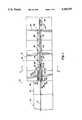
- FIG. 1is a somewhat schematic side elevational view of a glass sheet strip annealing lehr constructed in accordance with the present invention
- FIG. 2is a partially broken away perspective view of an entry end of a housing of the annealing lehr;
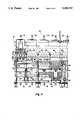
- FIG. 3is a cross-sectional view of the annealing lehr taken generally along the direction of line 3--3 in FIG. 1;
- FIG. 4is a side elevational view of the annealing lehr taken along the direction of line 4--4 in FIG. 3;
- FIG. 5is a partially broken away perspective view of a platen of a manifold of the annealing lehr through which pressurized gas is fed for recirculating flow to support and slowly cool the glass sheet strip during the annealing;
- FIG. 6is a plan view of the platen taken along the direction of line 6--6 in FIG. 3 and illustrates the construction of supply and exhaust openings through which the pressurized gas is fed for recirculating flow;
- FIG. 7is a sectional view taken along the direction of line 7--7 in FIG. 3 through lower and upper platens of lower and upper manifolds and illustrates the way in which the pressurized gas is recirculated for impingement with the glass sheet strip;
- FIG. 8is a perspective view illustrating another embodiment of the manifold.
- a glass sheet forming systemis generally indicated by 10 and includes a forming station 12 at which a continuous hot glass sheet strip G is formed, a trimming station 14 at which the lateral edge portions of the hot glass sheet strip are trimmed, and an annealing lehr 16 that is constructed in accordance with the present invention to provide annealing of the glass sheet strip prior to cutting of the strip into glass sheets of discrete lengths.
- the forming station 12may be of any conventional construction but normally will provide forming of the hot glass sheet strip G by floating thereof on a bath of molten metal that conventionally is hot tin.
- the glass sheet strip GAfter leaving the forming station 12, the glass sheet strip G passes through the trimming station 14 as mentioned above where its lateral edge portions may be trimmed to remove any edge irregularities present prior to entering the annealing lehr 16 for annealing.
- the trimming station 14As mentioned above where its lateral edge portions may be trimmed to remove any edge irregularities present prior to entering the annealing lehr 16 for annealing.
- any type of forming of the glass sheet strip Gcan be utilized and that it is not absolutely necessary for edge trimming to be performed prior to delivery of the glass sheet strip to the annealing lehr 16 of the present invention for the slow cooling that provides annealing.
- the glass sheet strip annealing lehr 16 of this inventionincludes a housing 18 defining a heated chamber 20 and has an entry end 22 for receiving the continuous hot glass sheet strip G just after forming of the strip.
- the housing 18also has an exit end 24 from which the glass sheet strip exits the heated chamber 20.
- the heated chamber 20has a decreasing temperature from the entry end 22 of the housing toward the exit end 24 of the housing to provide relatively slow cooling that anneals the glass sheet strip G.
- a conveyor 26 of the annealing lehrincludes a gas support 28 that delivers upwardly directed pressurized gas as illustrated by arrows 30 in FIG. 7.
- This upwardly directed pressurized gasprovides the sole support of the glass sheet strip within the annealing lehr housing 18 shown in FIG. 1 until the surfaces of the strip are cooled below the strain point.
- a drive 32 of the conveyor 26engages the glass sheet strip G as shown in FIG. 1 after the surfaces thereof are cooled below the strain point and pulls the strip from the entry end 22 of the housing toward the exit end 24 thereof over the gas support 28.
- the surfaces of the glass sheet strip Gare not mechanically engaged during the annealing within the annealing lehr housing 18 in order to preserve optical qualities of the glass sheets that are ultimately cut from the continuous strip.
- the gas support 28provides the sole support for the glass sheet strip G until the surfaces of the glass sheet strip are placed in compression by the cooling. More specifically, this compression of the surfaces is generated after the glass sheet strip has been cooled sufficiently so that the temperature gradient between its surfaces and its center begins to disappear as the cooling slows at ambient temperature.
- the drive 32then engages the glass sheet strip after the surfaces thereof are placed in compression by the cooling to pull the strip from the entry end 22 of the housing 18 toward the exit end 24 thereof over the gas support 28 of conveyor 26.
- the gas support 28 of the conveyor 26preferably includes a lower manifold 34 to which the pressurized gas is fed for upward flow that impinges with the glass sheet strip G to provide the support of the strip as illustrated by arrows 30 in FIG. 7.
- the gas support 28 illustrated in FIGS. 1 and 3also includes an upper manifold 36 to which gas is fed for downwardly directed flow that impinges with the glass sheet strip G as illustrated by arrows 38 in FIG. 7 to cooperate with the upward gas flow in providing uniform forced convection heat transfer with the lower and upper surfaces of the glass sheet strip G.
- each of the lower and upper manifolds 34 and 36includes supply openings 40 through which the pressurized gas is fed for impingement with the glass sheet strip G.
- Each of the lower and upper manifolds 34 and 36also includes exhaust openings 42 through which the gas is exhausted after impingement with the glass sheet strip G as illustrated in FIG. 7 by arrows 44 and 46 respectively associated with the lower and upper manifolds.
- Each of the manifolds as shown in FIG. 6has a horizontally extending planar surface 48 at which the supply and exhaust openings are defined.
- These supply and exhaust openings 40 and 42preferably have elongated slit shapes that extend transversely with respect to the direction of movement of the glass sheet strip as identified by arrow 50.
- Each elongated exhaust opening 42has opposite ends 52 and a central portion 54 between the opposite ends. These exhaust openings 42 each have a progressively increasing flow area in a direction from its ends 52 toward the central portion 54 thereof to prevent a gas pressure buildup at the center of the glass sheet strip. More specifically, as illustrated, the exhaust openings 42 have an increasing width from the ends 52 toward the central portion 54 to prevent the gas pressure buildup at the center of the glass sheet strip which is adjacent the central portion 54 of the exhaust openings.
- each of the lower and upper manifolds 34 and 36has supply passages 56 that are inclined and feed the supply openings 40 so as to provide driving of the glass sheet strip by the pressurized gas flow toward the exit end of the housing.
- This drivingtakes place by providing the inclination to the upward and downward gas flows identified by arrows 30 and 36 such that these gas flows tend to move the glass sheet G in the direction of arrow 50 which is toward the exit end of the housing.
- the conveyor 26preferably includes a plurality of sets of the lower and upper manifolds 34 and 36 between the entry and exit ends 22 and 24 of the housing 18 of the annealing lehr 16. More specifically, five sets of the lower and upper manifolds 34 and 36 are illustrated; however, a greater or less number of the manifold sets can be utilized depending upon sizing and the processing parameters desired.
- each of the lower and upper manifolds 34 and 36is molded from a suitable refractory material such as sinter bonded fused silica so as to have good resistance to thermal warpage. More specifically, each manifold includes a cast platen 60 that defines the surface 48 in which the supply and exhaust openings are located with the constructions previously described. Each platen 60 also has a surface 62 that extends parallel to its planar surface 48 and defines elongated plenum portions 64 extending therefrom with an initially converging shape to feed the supply passages 56 that feed the pressurized gas to the supply openings 40 as previously described.
- Each platen 60also includes elongated exhaust chambers 66 that receive gas from the exhaust passages 58 and have opposite ends that are communicated with associated return passages 68 shown in FIG. 5.
- An associated end wall 70isolates each return passage 68 from the adjacent plenum portion 64 while providing the communication thereof with the exhaust chambers 66 so as to permit recirculating flow of the gas as is hereinafter more fully described.
- each of the lower and upper manifolds 34 and 36also includes a cast manifold member 72 that feeds the pressurized gas to the supply openings of the associated platen 60 and receives the gas from the exhaust openings of the platen for recirculating flow back to the supply openings.
- cast manifold member 72that feeds the pressurized gas to the supply openings of the associated platen 60 and receives the gas from the exhaust openings of the platen for recirculating flow back to the supply openings.
- These manifolds 72are respectively located below and above the platen 60 of the lower and upper manifolds and are secured thereto by associated bolt-type fasteners 74.
- each of the lower and upper manifolds 34 and 36additionally includes a gas burner 76 and at least one gas jet pump 78 mounted by the manifold member 72.
- gas jet pumps 78mounted by each manifold member 72, specifically nine each side thereof, and as illustrated in FIG. 4 these gas jet pumps are located in a staggered array of lower and upper sets.
- Each of these gas jet pumpsis connected by feeder conduits 80 fed by an associated main conduit 82 from a mixing chamber 84 to which the heated products of combustion are fed from the associated gas burner 76.
- These heated products of combustionare fed to the gas jet pumps 78 for flow through a restricted nozzle 86 to provide a primary gas flow 88 that induces a secondary flow 90 of the return gas received from the exhaust openings of the associated platen 60 for recirculating flow of the mixed gas as shown by arrows 92 back to the supply openings.
- Delivery members 94feed the mixed flow back to the supply openings as is hereinafter more fully described.
- each manifold member 72includes two pairs of spaced outer and inner side walls 96 and 98 that extend generally vertically from a horizontal wall 100 to the associated platen 60.
- Each pair of outer and inner spaced side walls 96 and 98defines a return passage 102 for receiving gas from the exhaust openings of the platen via the return passages 68 previously described in connection with FIG. 5.
- a plurality of the gas jet pumps 78are associated with each manifold 34 and 36 and are mounted on each pair of spaced side walls 96 and 98 thereof in staggered lower and upper sets.
- These gas jet pumpsfunction to mix the pressurized and heated products of combustion received from the gas burner 76 through the feeder and main conduits 80 and 82 and the mixing chamber 84 so as to mix with the gas returned from the exhaust openings of the associated platen 60 for recirculating flow back to the supply openings of the platen.
- the two pairs of spaced side walls 96 and 98are also spaced from each other to cooperate with each other and with the horizontal wall 100 thereof as well as the surface 62 of the associated platen to define a mixing plenum 104 in which the pressurized gas is received from opposite directions from the gas jet pumps for mixing prior to being fed to the supply openings of the platen as previously described in connection with FIG. 7.
- This mixing plenum chamber 104is divided by vertical walls 105 spaced as shown in FIG. 2 along the length of the lehr along which the glass sheet strip is moved
- a pair of the gas jet pumps 78feed pressurized gas between each pair of vertical walls 105 from opposite directions at upper and lower positions that alternate along the direction of the glass sheet strip movement.
- Such a constructionprovide a circular mixing as shown by arrows 103 in FIG. 3 to thereby provide pressure and temperature uniformity. Any variation in the gas delivery pressure and temperature over the lateral width of the manifolds due to the upper and lower locations of the two gas jet pumps 78 that feed between each pair of vertical walls 105 is accommodated for by the alternating relationship of these positions along the direction of movement of the glass sheet strip. Furthermore, pressure variations along the lateral width are the same both above and below the glass sheet strip G in order to maintain planarity.
- each manifold member 72also includes temperature controllers 106 for controlling the temperature of the pressurized gas delivered from the mixing chamber to the supply openings of the associated platen 60. More specifically, each temperature controller 106 as shown in FIG. 2 includes an electric resistance element 108 to which a voltage is applied as needed to provide the appropriate temperature at the particular location involved so as to provide the proper degree of heating at that location of the annealing lehr.
- These temperature controllers 106are mounted between vertical walls 105 by the spaced side walls 96 and 98 of the associated manifold member 72 toward the glass sheet strip from the gas jet pumps 78 such that all of the gas delivered from the gas jet pumps must pass by the temperature controllers and thus be heated thereby so as to provide the proper temperature of the pressurized gas delivered to the supply openings.
- One temperature controller 106 and two gas jet pumps 78are mounted between each pair of vertical walls 105 of the manifold member 72. The good temperature control achieved with the lehr allows nonlinear cooling that can decrease the time needed to perform the annealing.
- the glass sheet strip Gis floated by the pressurized gas above the planar surface 48 of each lower manifold 34 a very small distance, such as about 1 to 2 millimeters, and is spaced below the planar surface 48 of each upper manifold 36 by a distance that is normally greater than the lower spacing such as two to several times the lower spacing.
- the extent of each spacing for best resultsdepends upon glass thickness, the speed of conveyance, the temperature involved and other operating parameters.
- FIG. 8another construction for the lower and upper manifolds is illustrated by the one lower manifold 34' shown by solid line representation.
- This manifoldis fabricated from sheet metal as opposed to being molded from refractory material like the previously described embodiment and is utilized with a plurality of like lower manifolds 34' and, preferably, with a plurality of like upper manifolds 36' as shown by phantom line representation so that the glass sheet strip can be conveyed therebetween in a generally similar manner to the previously described embodiment.
- the manifold 34'has a gas supply opening 40' of an elongated shape that extends transversely to the direction of movement of the glass sheet strip as with the previously described embodiment.
- the lower manifold 34'has a construction for cooperating with the planar upstream side of the adjacent lower manifold 34' to define an exhaust openings 42' of an elongated shape that receives the gas after impingement with the glass sheet strip.
- This exhaust openinghas opposite ends 52' and a central portion 54'.
- the elongated gas exhaust opening 42'has a progressively increasing flow area in a direction toward the central portion 54' thereof from its opposite ends 52' so as to prevent a gas pressure buildup at the center of the conveyed glass sheet strip.
- the fabricated sheet metal embodiment of the manifold 34'provides the increasing flow area by a progressively increasing depth of the exhaust opening 42' from its ends 52' toward its central portion 54'.
- Hot pressurized gassuch as from the products of combustion of an associated gas burner are fed into side inlets 110 for flow to the supply openings 40' preferably through supply passages 56' that are inclined like with the previously described embodiment.
- the conveyor drive 32 of the annealing lehr 16includes at least one roller 112 that engages the lower surface of the glass sheet strip G to pull the strip from the entry end 22 of the housing 18 toward the exit end 24 thereof over the gas support 28 provided by the gas manifolds as previously described.
- the roller drive 32will also include other rollers of a conveyor on which final cooling takes place.
- the annealing lehrincludes a framework generally designated by 114 for supporting the components of the housing 18.
- This housing framework 114includes vertical legs 116 and horizontal beams 118 that extend between and are supported by the legs.
- Each lower manifold 34has four associated lower jacks 120 whose lower ends are supported by an associated horizontal beam 118 and whose upper ends support the adjacent corner of the manifold member 72.
- These jacks 120extend through an insulated floor 122 of the housing 18 just inward from insulated lower side walls 124 of the housing.
- Upper vertical jacks 126 of the framework 114have lower ends supported by adjacent horizontal beams 118 and have vertically movable carriages 128 that are connected as shown in FIG. 2 by coupling shafts 130 along the longitudinal length of the housing.
- suspension rods 138 and 140support each upper manifold 36. More specifically, four of the suspension rods 138 have upper ends supported by the insulated ceiling 134 and have lower ends that support the four corners of the platen 60 of the upper manifold 36. Likewise, four of the suspension rods 140 have upper ends also supported by the insulated ceiling 134 and have lower ends that support the four corners of the manifold member 72 of the associated upper manifold 36.
- suspension rods 138 and 140have threaded connections that provide securement so that the upper platen 60 is level, while vertical adjustment of the carriages 128 as previously described spaces the upper platen 60 at the appropriate elevation with respect to the lower platen 60 whose elevation is controlled by the lower jacks 120 as previously described.
- vertically movable doors 142that are preferably constructed of ceramic material such as by molding from sinter bonded fused silica particles are located at each side of the upper platen 60.
- a pair of chains 144are connected to the doors 142 and extend over pulleys 146 mounted on the horizontally extending beams 132 in a suitable manner, and from the pulleys the chains 144 extend downwardly to a horizontal handle 148 that is movable downwardly to thus pull the door 142 upwardly and permit viewing of the glass sheet strip at the adjacent location.
- windows 150are located between the adjacent upper manifolds 36 to permit viewing of the conveyed glass sheet strip in addition to the viewing permitted by the opening of the doors 142 as previously described in connection with FIGS. 2 and 3.
- a cullet door mechanism 152is located at one side of the housing 18 and controls positioning of a lower cullet door 154 between a horizontal closed position that maintains the pressurized atmosphere within the lehr housing 18 and a vertical open position that permits cullet to fall downwardly when the glass sheet strip is broken.
- start-up rolls 156are located between alternate sets of the lower and upper manifolds and normally positioned during steady state operation below the glass sheet strip by associated positioning and drive mechanisms 158. During start-up operation, these mechanisms 158 raise the start-up rolls 156 to initially convey the glass sheet strip G through the annealing layer in order to facilitate reaching the steady state operation as previously described. Between each adjacent pair of start-up roll drive mechanisms 158, the annealing layer includes a pyrometer assembly 160 for measuring the temperature profile of the glass sheet strip along its lateral width during the conveyance.
Landscapes
- Chemical & Material Sciences (AREA)
- Engineering & Computer Science (AREA)
- Materials Engineering (AREA)
- Organic Chemistry (AREA)
- Re-Forming, After-Treatment, Cutting And Transporting Of Glass Products (AREA)
Abstract
Description
Claims (17)
Priority Applications (8)
| Application Number | Priority Date | Filing Date | Title |
|---|---|---|---|
| US07/671,505US5209767A (en) | 1991-03-19 | 1991-03-19 | Glass sheet annealing lehr having gas support conveyor |
| PCT/US1992/001747WO1992016466A1 (en) | 1991-03-19 | 1992-03-06 | Glass sheet annealing lehr having gas support conveyor |
| JP4508766AJPH06506180A (en) | 1991-03-19 | 1992-03-06 | Glass plate lehr kiln with gas support conveyor |
| EP92909027AEP0576582A4 (en) | 1991-03-19 | 1992-03-06 | GLASS DISC COOLER WITH GAS CARRYING TRANSPORTER. |
| KR1019930702791AKR0185751B1 (en) | 1991-03-19 | 1992-03-06 | Glass Plate Annealing Chiller With Gas Bracket Conveyor |
| AU16784/92AAU1678492A (en) | 1991-03-19 | 1992-03-06 | Glass sheet annealing lehr having gas support conveyor |
| US08/383,602US5700306A (en) | 1991-03-19 | 1995-01-31 | Glass sheet strip forming system including annealing lehr |
| US08/946,826US5948132A (en) | 1991-03-19 | 1997-10-08 | Glass sheet strip annealing method |
Applications Claiming Priority (1)
| Application Number | Priority Date | Filing Date | Title |
|---|---|---|---|
| US07/671,505US5209767A (en) | 1991-03-19 | 1991-03-19 | Glass sheet annealing lehr having gas support conveyor |
Related Child Applications (1)
| Application Number | Title | Priority Date | Filing Date |
|---|---|---|---|
| US99216992AContinuation | 1991-03-19 | 1992-12-17 |
Publications (1)
| Publication Number | Publication Date |
|---|---|
| US5209767Atrue US5209767A (en) | 1993-05-11 |
Family
ID=24694788
Family Applications (3)
| Application Number | Title | Priority Date | Filing Date |
|---|---|---|---|
| US07/671,505Expired - LifetimeUS5209767A (en) | 1991-03-19 | 1991-03-19 | Glass sheet annealing lehr having gas support conveyor |
| US08/383,602Expired - LifetimeUS5700306A (en) | 1991-03-19 | 1995-01-31 | Glass sheet strip forming system including annealing lehr |
| US08/946,826Expired - LifetimeUS5948132A (en) | 1991-03-19 | 1997-10-08 | Glass sheet strip annealing method |
Family Applications After (2)
| Application Number | Title | Priority Date | Filing Date |
|---|---|---|---|
| US08/383,602Expired - LifetimeUS5700306A (en) | 1991-03-19 | 1995-01-31 | Glass sheet strip forming system including annealing lehr |
| US08/946,826Expired - LifetimeUS5948132A (en) | 1991-03-19 | 1997-10-08 | Glass sheet strip annealing method |
Country Status (6)
| Country | Link |
|---|---|
| US (3) | US5209767A (en) |
| EP (1) | EP0576582A4 (en) |
| JP (1) | JPH06506180A (en) |
| KR (1) | KR0185751B1 (en) |
| AU (1) | AU1678492A (en) |
| WO (1) | WO1992016466A1 (en) |
Cited By (13)
| Publication number | Priority date | Publication date | Assignee | Title |
|---|---|---|---|---|
| US5672191A (en)* | 1994-06-20 | 1997-09-30 | Gas Research Institute | Forced convection heating apparatus and process for heating glass sheets therewithin |
| US5700306A (en)* | 1991-03-19 | 1997-12-23 | Glasstech, Inc. | Glass sheet strip forming system including annealing lehr |
| US5746799A (en)* | 1994-06-20 | 1998-05-05 | Gas Research Institute | Process for heating glass sheets within a forced convection heating apparatus by mixing and distributing spent working fluid and combustion gases |
| US5762674A (en)* | 1995-09-27 | 1998-06-09 | Glasstech, Inc. | Apparatus for coating glass sheet ribbon |
| US5762677A (en)* | 1994-06-20 | 1998-06-09 | Gas Research Institute | Process for heating glass sheets within a forced convection heating apparatus by controlling temperature |
| US6045358A (en)* | 1996-01-19 | 2000-04-04 | Glasstech, Inc. | Forced convection heating apparatus and process for heating glass sheets therewithin |
| US20030074922A1 (en)* | 2001-10-23 | 2003-04-24 | Glasstech, Inc. | Forced convection heating furnace and method for heating glass sheets |
| US20040073090A1 (en)* | 1999-10-14 | 2004-04-15 | John Butler | Wound retractor |
| US8800322B1 (en)* | 2010-09-23 | 2014-08-12 | WD Media, LLC | Composite magnetic recording medium |
| US8834962B2 (en) | 2011-06-03 | 2014-09-16 | WD Media, LLC | Methods for improving the strength of glass substrates |
| US20150068250A1 (en)* | 2012-04-23 | 2015-03-12 | Kamil Alimovich Ablyazov | Method for producing float glass |
| US20150246839A1 (en)* | 2012-09-21 | 2015-09-03 | Agc Glass Europe | Method for cambering glass sheets |
| US20170247280A1 (en)* | 2014-06-24 | 2017-08-31 | China Triumph International Engineering Co., Ltd. | Isothermal drop speed cooling method of forced convection area for lehr and the apparatus thereof |
Families Citing this family (19)
| Publication number | Priority date | Publication date | Assignee | Title |
|---|---|---|---|---|
| IT1262463B (en)* | 1993-11-30 | 1996-06-19 | Siv Soc Italiana Vetro | PROCEDURE AND DEVICE FOR THE MANUFACTURE OF FLAT GLASS WITH IMPROVED CHARACTERISTICS. |
| DE19649488A1 (en)* | 1996-11-29 | 1997-11-06 | Schott Glaswerke | Pneumatic handling or transport system and for thin glass sheet in display manufacture |
| DE19805907C2 (en)* | 1998-02-13 | 2001-02-22 | Schott Glas | Glass and glass ceramic plates with increased thermal resistance and process for their production |
| FR2797627B1 (en)* | 1999-08-19 | 2001-10-26 | Stein Heurtey | IMPROVEMENTS RELATING TO FLAT GLASS COLLECTION RACKS |
| FI110866B (en)* | 2000-08-28 | 2003-04-15 | Tamglass Ltd Oy | Method for heating LowE glass sheets in a curing kid |
| DE10330196B4 (en)* | 2003-07-03 | 2009-11-05 | Erdmann, Wolfgang | Plant for the heat treatment of glass |
| FI119421B (en)* | 2004-02-20 | 2008-11-14 | Tamglass Ltd Oy | Dehumidifier for laminated glass sheets |
| US20060018449A1 (en)* | 2004-07-20 | 2006-01-26 | Qwest Communications International Inc. | Telephone call routing |
| WO2007139903A2 (en)* | 2006-05-25 | 2007-12-06 | Massachusetts Institute Of Technology | Method for shaping sheet thermoplastic and the like |
| US20080022721A1 (en)* | 2006-07-25 | 2008-01-31 | Bernd Disteldorf | Method of making glass including surface treatment with aluminum chloride at or just prior to annealing lehr |
| US8677782B2 (en)* | 2006-07-25 | 2014-03-25 | Guardian Industries Corp. | Method of making glass including surface treatment with aluminum chloride at or just prior to annealing LEHR |
| US7923063B2 (en) | 2007-12-10 | 2011-04-12 | Centre Luxembourgeois De Recherches Pour Le Verre Et La Ceramique S.A. (C.R.V.C.) | Method of making glass including surface treatment with aluminum chloride using combustion deposition prior to deposition of antireflective coating |
| JP5380902B2 (en)* | 2008-05-12 | 2014-01-08 | 富士電機株式会社 | Temperature control device and temperature control system |
| CN101880124B (en)* | 2010-05-28 | 2012-11-07 | 武汉理工大学 | Annealing and cooling treatment system for two-stage hot wind circulation of glass ceramic tunnel crystallization kiln |
| JP5679007B2 (en)* | 2013-07-02 | 2015-03-04 | 富士電機株式会社 | Temperature control system |
| US9611166B2 (en) | 2014-10-02 | 2017-04-04 | Glasstech, Inc. | Glass quench apparatus |
| US10927030B2 (en) | 2017-05-31 | 2021-02-23 | Robex, LLC | Glass product annealing lehr with temperature control system |
| CN111386235B (en)* | 2017-10-31 | 2023-04-07 | 康宁公司 | System and method for processing thin glass ribbon |
| WO2021124801A1 (en)* | 2019-12-18 | 2021-06-24 | 日本電気硝子株式会社 | Glass article manufacturing method and glass article manufacturing device |
Citations (12)
| Publication number | Priority date | Publication date | Assignee | Title |
|---|---|---|---|---|
| US1622817A (en)* | 1927-03-29 | Brothers limited | ||
| US1848097A (en)* | 1929-09-07 | 1932-03-08 | Libbey Owens Ford Glass Co | Process and apparatus for producing sheet glass |
| US3070901A (en)* | 1956-02-01 | 1963-01-01 | Svenska Flaektfabriken Ab | Guiding air-borne webs |
| US3223498A (en)* | 1962-02-27 | 1965-12-14 | Pittsburgh Plate Glass Co | Heat treatment of conveyed glass and apparatus therefor |
| US3294518A (en)* | 1963-07-19 | 1966-12-27 | Pittsburgh Plate Glass Co | Apparatus for tempering bent glass sheets |
| US3355275A (en)* | 1963-05-24 | 1967-11-28 | Pittsburgh Plate Glass Co | Method of forming a glass ribbon on a gas support bed |
| US3506422A (en)* | 1964-04-11 | 1970-04-14 | Libbey Owens Ford Co | Method and apparatus for forming flat glass on a fluid support bed |
| US3687648A (en)* | 1968-06-14 | 1972-08-29 | Pilkington Brothers Ltd | Heating and bending of glass sheets during vertical conveyance |
| US4059426A (en)* | 1976-10-01 | 1977-11-22 | Ppg Industries, Inc. | Method and apparatus for heating glass sheets with recirculated gas |
| US4749400A (en)* | 1986-12-12 | 1988-06-07 | Ppg Industries, Inc. | Discrete glass sheet cutting |
| US5018661A (en)* | 1988-11-25 | 1991-05-28 | Cyb Frederick F | Heat-resistant exhaust manifold and method of preparing same |
| US5078775A (en)* | 1991-03-19 | 1992-01-07 | Glasstech, Inc. | Glass sheet gas support |
Family Cites Families (17)
| Publication number | Priority date | Publication date | Assignee | Title |
|---|---|---|---|---|
| BE622749A (en)* | 1961-09-22 | |||
| US3455669A (en)* | 1966-05-09 | 1969-07-15 | Permaglass | Apparatus for heat treating glass on a fluid support |
| US3455671A (en)* | 1966-05-09 | 1969-07-15 | Permaglass | Gas support bed apparatus for treating glass |
| US3488173A (en)* | 1966-07-07 | 1970-01-06 | Permaglass | Method and apparatus for heat treating and conveying glass sheets on a gas support bed |
| US3481724A (en)* | 1966-07-21 | 1969-12-02 | Ppg Industries Inc | Method and apparatus for tempering glass sheets between opposed gas flows |
| US3523776A (en)* | 1967-03-15 | 1970-08-11 | Permaglass | Method and apparatus for manufacturing sheet glass |
| US3497340A (en)* | 1968-07-29 | 1970-02-24 | Ppg Industries Inc | Method of tempering and reshaping glass sheets |
| US3607173A (en)* | 1969-03-14 | 1971-09-21 | Permaglass | Method and apparatus for heat treating sheets of glass |
| US3847580A (en)* | 1970-05-25 | 1974-11-12 | Ppg Industries Inc | Method of tempering glass |
| US3701266A (en)* | 1970-06-08 | 1972-10-31 | Ppg Industries Inc | Method of tempering glass in a liquid |
| US3881907A (en)* | 1974-01-30 | 1975-05-06 | Ppg Industries Inc | Method of tempering glass sheets |
| US3918950A (en)* | 1974-12-03 | 1975-11-11 | Ppg Industries Inc | Glass sheet tempering |
| US4081260A (en)* | 1976-12-13 | 1978-03-28 | Mark Leonovich Glikman | Process for making sheet glass on a fluid support |
| US4200446A (en)* | 1979-01-29 | 1980-04-29 | Ppg Industries, Inc. | Gas hearth electrical heating supplement and method of operation |
| US4886540A (en)* | 1988-07-25 | 1989-12-12 | Glasstech International L.P. | Blow back control device for a glass sheet tempering system |
| US5209767A (en)* | 1991-03-19 | 1993-05-11 | Glasstech, Inc. | Glass sheet annealing lehr having gas support conveyor |
| US5380348A (en)* | 1993-06-21 | 1995-01-10 | Ford Motor Company | Method for treating glass sheets on a gas hearth |
- 1991
- 1991-03-19USUS07/671,505patent/US5209767A/ennot_activeExpired - Lifetime
- 1992
- 1992-03-06AUAU16784/92Apatent/AU1678492A/ennot_activeAbandoned
- 1992-03-06JPJP4508766Apatent/JPH06506180A/enactivePending
- 1992-03-06KRKR1019930702791Apatent/KR0185751B1/ennot_activeExpired - Fee Related
- 1992-03-06WOPCT/US1992/001747patent/WO1992016466A1/ennot_activeApplication Discontinuation
- 1992-03-06EPEP92909027Apatent/EP0576582A4/ennot_activeCeased
- 1995
- 1995-01-31USUS08/383,602patent/US5700306A/ennot_activeExpired - Lifetime
- 1997
- 1997-10-08USUS08/946,826patent/US5948132A/ennot_activeExpired - Lifetime
Patent Citations (12)
| Publication number | Priority date | Publication date | Assignee | Title |
|---|---|---|---|---|
| US1622817A (en)* | 1927-03-29 | Brothers limited | ||
| US1848097A (en)* | 1929-09-07 | 1932-03-08 | Libbey Owens Ford Glass Co | Process and apparatus for producing sheet glass |
| US3070901A (en)* | 1956-02-01 | 1963-01-01 | Svenska Flaektfabriken Ab | Guiding air-borne webs |
| US3223498A (en)* | 1962-02-27 | 1965-12-14 | Pittsburgh Plate Glass Co | Heat treatment of conveyed glass and apparatus therefor |
| US3355275A (en)* | 1963-05-24 | 1967-11-28 | Pittsburgh Plate Glass Co | Method of forming a glass ribbon on a gas support bed |
| US3294518A (en)* | 1963-07-19 | 1966-12-27 | Pittsburgh Plate Glass Co | Apparatus for tempering bent glass sheets |
| US3506422A (en)* | 1964-04-11 | 1970-04-14 | Libbey Owens Ford Co | Method and apparatus for forming flat glass on a fluid support bed |
| US3687648A (en)* | 1968-06-14 | 1972-08-29 | Pilkington Brothers Ltd | Heating and bending of glass sheets during vertical conveyance |
| US4059426A (en)* | 1976-10-01 | 1977-11-22 | Ppg Industries, Inc. | Method and apparatus for heating glass sheets with recirculated gas |
| US4749400A (en)* | 1986-12-12 | 1988-06-07 | Ppg Industries, Inc. | Discrete glass sheet cutting |
| US5018661A (en)* | 1988-11-25 | 1991-05-28 | Cyb Frederick F | Heat-resistant exhaust manifold and method of preparing same |
| US5078775A (en)* | 1991-03-19 | 1992-01-07 | Glasstech, Inc. | Glass sheet gas support |
Cited By (21)
| Publication number | Priority date | Publication date | Assignee | Title |
|---|---|---|---|---|
| US5700306A (en)* | 1991-03-19 | 1997-12-23 | Glasstech, Inc. | Glass sheet strip forming system including annealing lehr |
| US5948132A (en)* | 1991-03-19 | 1999-09-07 | Glasstech, Inc. | Glass sheet strip annealing method |
| US5672191A (en)* | 1994-06-20 | 1997-09-30 | Gas Research Institute | Forced convection heating apparatus and process for heating glass sheets therewithin |
| US5735924A (en)* | 1994-06-20 | 1998-04-07 | Gas Research Institute | Process for heating glass sheets therewithin a forced convection heating apparatus by controlling impingement velocity |
| US5746799A (en)* | 1994-06-20 | 1998-05-05 | Gas Research Institute | Process for heating glass sheets within a forced convection heating apparatus by mixing and distributing spent working fluid and combustion gases |
| US5762677A (en)* | 1994-06-20 | 1998-06-09 | Gas Research Institute | Process for heating glass sheets within a forced convection heating apparatus by controlling temperature |
| US5792232A (en)* | 1994-06-20 | 1998-08-11 | Gas Research Institute | Forced convection heating apparatus |
| US5762674A (en)* | 1995-09-27 | 1998-06-09 | Glasstech, Inc. | Apparatus for coating glass sheet ribbon |
| US5876474A (en)* | 1995-09-27 | 1999-03-02 | Glasstech, Inc. | Method for coating glass sheet ribbon |
| US6013375A (en)* | 1995-09-27 | 2000-01-11 | Glasstech, Inc. | Coated glass sheet |
| US6045358A (en)* | 1996-01-19 | 2000-04-04 | Glasstech, Inc. | Forced convection heating apparatus and process for heating glass sheets therewithin |
| US20040073090A1 (en)* | 1999-10-14 | 2004-04-15 | John Butler | Wound retractor |
| US20030074922A1 (en)* | 2001-10-23 | 2003-04-24 | Glasstech, Inc. | Forced convection heating furnace and method for heating glass sheets |
| US6668590B2 (en)* | 2001-10-23 | 2003-12-30 | Glasstech, Inc. | Forced convection heating furnace and method for heating glass sheets |
| US8800322B1 (en)* | 2010-09-23 | 2014-08-12 | WD Media, LLC | Composite magnetic recording medium |
| US8834962B2 (en) | 2011-06-03 | 2014-09-16 | WD Media, LLC | Methods for improving the strength of glass substrates |
| US20150068250A1 (en)* | 2012-04-23 | 2015-03-12 | Kamil Alimovich Ablyazov | Method for producing float glass |
| US20150246839A1 (en)* | 2012-09-21 | 2015-09-03 | Agc Glass Europe | Method for cambering glass sheets |
| US10486999B2 (en)* | 2012-09-21 | 2019-11-26 | Agc Glass Europe | Method for cambering glass sheets |
| US20170247280A1 (en)* | 2014-06-24 | 2017-08-31 | China Triumph International Engineering Co., Ltd. | Isothermal drop speed cooling method of forced convection area for lehr and the apparatus thereof |
| US11505489B2 (en)* | 2014-06-24 | 2022-11-22 | China Triumph International Engineering Co., Ltd. | Isothermal drop speed cooling method of forced convection area for lehr and the apparatus thereof |
Also Published As
| Publication number | Publication date |
|---|---|
| US5948132A (en) | 1999-09-07 |
| EP0576582A4 (en) | 1995-02-15 |
| JPH06506180A (en) | 1994-07-14 |
| WO1992016466A1 (en) | 1992-10-01 |
| EP0576582A1 (en) | 1994-01-05 |
| KR0185751B1 (en) | 1999-04-15 |
| AU1678492A (en) | 1992-10-21 |
| US5700306A (en) | 1997-12-23 |
Similar Documents
| Publication | Publication Date | Title |
|---|---|---|
| US5209767A (en) | Glass sheet annealing lehr having gas support conveyor | |
| US6092393A (en) | Method for heating moving glass sheets | |
| US3332761A (en) | Method of annealing sheets of glass on a decreasing temperature gas support | |
| US5125948A (en) | Heat conditioning chamber | |
| US3223499A (en) | Method of treating and conveying glass sheets | |
| CZ284689B6 (en) | Apparatus for bending glass sheets | |
| JP2003523916A (en) | Glass transfer system | |
| JP2824303B2 (en) | Glass plate tempering method and apparatus | |
| EP2297054B1 (en) | Manufacturing method of cellular ceramic plates with asymmetrical cell structure | |
| US4481025A (en) | Glass annealing lehr | |
| US3942967A (en) | Heat treatment of glass sheets | |
| US3223498A (en) | Heat treatment of conveyed glass and apparatus therefor | |
| US4182619A (en) | Method of toughening glass sheets | |
| US3300290A (en) | Method and apparatus for conveying and heating glass on a fluid support bed | |
| IE47501B1 (en) | Method for thermally toughening glass sheets,in particular to be used as motor vehicle side or rear windows | |
| US4111676A (en) | Adaptation of glass shaping means for tempering flat glass | |
| KR20060009340A (en) | Glass Panel Bending Method and Bending Furnace | |
| US20210009458A1 (en) | Device for annealing glass panes | |
| US3223506A (en) | Method and apparatus for vertically supporting and heat treating a glass sheet | |
| US3362806A (en) | Methods of heat treating and gas pressure supporting glass in sheet form | |
| US5330549A (en) | Apparatus for the manufacture of sheets of glass having a complex shape | |
| US3355275A (en) | Method of forming a glass ribbon on a gas support bed | |
| US3294510A (en) | Apparatus for and process of annealing glass as it is being drawn upwardly | |
| US3311463A (en) | Process of annealing glass sheets | |
| RU2081067C1 (en) | Apparatus for molding and tempering glass sheets |
Legal Events
| Date | Code | Title | Description |
|---|---|---|---|
| AS | Assignment | Owner name:GLASSTECH, INC.,, OHIO Free format text:ASSIGNMENT OF ASSIGNORS INTEREST.;ASSIGNORS:MALTBY, ROBERT E., JR.;MCMASTER, HAROLD A.;BRENO, PHILIP J.;AND OTHERS;REEL/FRAME:005706/0445;SIGNING DATES FROM 19910306 TO 19910326 | |
| STCF | Information on status: patent grant | Free format text:PATENTED CASE | |
| AS | Assignment | Owner name:FIRST NATIONAL BANK OF BOSTON, THE (AS COLLATERAL Free format text:SECURITY INTEREST;ASSIGNOR:GLASSTECH, INC.;REEL/FRAME:007286/0036 Effective date:19950103 | |
| AS | Assignment | Owner name:GLASSTECH, INC., OHIO Free format text:ASSIGNMENT OF ASSIGNORS INTEREST;ASSIGNOR:VILD, MICHARL J.;REEL/FRAME:007648/0641 Effective date:19950911 | |
| FPAY | Fee payment | Year of fee payment:4 | |
| FPAY | Fee payment | Year of fee payment:8 | |
| AS | Assignment | Owner name:BANK OF AMERICA, N.A., ILLINOIS Free format text:SECURITY AGREEMENT;ASSIGNOR:GLASSTECH, INC.;REEL/FRAME:014268/0159 Effective date:20000929 | |
| AS | Assignment | Owner name:UPS CAPITAL CORPORATION, GEORGIA Free format text:SECURITY INTEREST;ASSIGNOR:GLASSTECH, INC.;REEL/FRAME:012896/0981 Effective date:20020708 | |
| FPAY | Fee payment | Year of fee payment:12 |