US5209752A - Lateral offset connector for spinal implant system - Google Patents
Lateral offset connector for spinal implant systemDownload PDFInfo
- Publication number
- US5209752A US5209752AUS07/803,325US80332591AUS5209752AUS 5209752 AUS5209752 AUS 5209752AUS 80332591 AUS80332591 AUS 80332591AUS 5209752 AUS5209752 AUS 5209752A
- Authority
- US
- United States
- Prior art keywords
- arms
- pair
- head portion
- connector
- grooves
- Prior art date
- Legal status (The legal status is an assumption and is not a legal conclusion. Google has not performed a legal analysis and makes no representation as to the accuracy of the status listed.)
- Expired - Lifetime
Links
- 239000007943implantSubstances0.000titleclaimsdescription11
- 210000000988bone and boneAnatomy0.000abstractdescription34
- 230000004048modificationEffects0.000description4
- 238000012986modificationMethods0.000description4
- 230000002159abnormal effectEffects0.000description2
- 210000003484anatomyAnatomy0.000description2
- 230000004075alterationEffects0.000description1
- 238000005452bendingMethods0.000description1
- 239000000560biocompatible materialSubstances0.000description1
- 230000004927fusionEffects0.000description1
- 230000013011matingEffects0.000description1
- 238000000034methodMethods0.000description1
- 230000001737promoting effectEffects0.000description1
- 230000000087stabilizing effectEffects0.000description1
- 229910001220stainless steelInorganic materials0.000description1
- 239000010935stainless steelSubstances0.000description1
- 238000001356surgical procedureMethods0.000description1
Images
Classifications
- A—HUMAN NECESSITIES
- A61—MEDICAL OR VETERINARY SCIENCE; HYGIENE
- A61B—DIAGNOSIS; SURGERY; IDENTIFICATION
- A61B17/00—Surgical instruments, devices or methods
- A61B17/56—Surgical instruments or methods for treatment of bones or joints; Devices specially adapted therefor
- A61B17/58—Surgical instruments or methods for treatment of bones or joints; Devices specially adapted therefor for osteosynthesis, e.g. bone plates, screws or setting implements
- A61B17/68—Internal fixation devices, including fasteners and spinal fixators, even if a part thereof projects from the skin
- A61B17/70—Spinal positioners or stabilisers, e.g. stabilisers comprising fluid filler in an implant
- A61B17/7001—Screws or hooks combined with longitudinal elements which do not contact vertebrae
- A61B17/7035—Screws or hooks, wherein a rod-clamping part and a bone-anchoring part can pivot relative to each other
- A61B17/7038—Screws or hooks, wherein a rod-clamping part and a bone-anchoring part can pivot relative to each other to a different extent in different directions, e.g. within one plane only
- A—HUMAN NECESSITIES
- A61—MEDICAL OR VETERINARY SCIENCE; HYGIENE
- A61B—DIAGNOSIS; SURGERY; IDENTIFICATION
- A61B17/00—Surgical instruments, devices or methods
- A61B17/56—Surgical instruments or methods for treatment of bones or joints; Devices specially adapted therefor
- A61B17/58—Surgical instruments or methods for treatment of bones or joints; Devices specially adapted therefor for osteosynthesis, e.g. bone plates, screws or setting implements
- A61B17/68—Internal fixation devices, including fasteners and spinal fixators, even if a part thereof projects from the skin
- A61B17/70—Spinal positioners or stabilisers, e.g. stabilisers comprising fluid filler in an implant
- A61B17/7001—Screws or hooks combined with longitudinal elements which do not contact vertebrae
- A61B17/7041—Screws or hooks combined with longitudinal elements which do not contact vertebrae with single longitudinal rod offset laterally from single row of screws or hooks
Definitions
- the present inventionbroadly concerns devices for use in spinal implant systems, particularly those using spinal rods contoured for connection at various locations along the length of the spinal column. More specifically, the invention concerns a device for fixing the spinal rod to a fixation element of the implant system which provides direct engagement to a vertebra of the spinal column.
- a bendable rodis longitudinally disposed adjacent the vertebral column and is fixed to various vertebrae along the length of the column by way of a number of fixation elements.
- fixation elementscan be provided, such as hooks or bone screws, which are configured to engage specific portions of the vertebra.
- TSRH® spinal system of Danek Medical, IncAn example of one such system is the TSRH® spinal system of Danek Medical, Inc.
- the hooks or screwsare engaged to the spinal rod by way of eyebolts.
- the eyeboltsare threaded onto the spinal rod and captured within yokes on the fixation hook or screw.
- a nutis threaded onto a threaded post of the eyebolt to clamp the yoke and rigidly fix the hook or screw element to the spinal fixation rod. Details of the TSRH spinal implant system are disclosed in the "Surgical Technique Manual" provided by Danek Medical, Inc., published in 1990, which disclosure is incorporated herein by reference.
- fixation elementshooks and/or screws
- spinal implant systemit is then possible to correct anatomical deformities and stabilize the spine.
- the fixation elementsare located in a colinear position substantially parallel to the vertebral column.
- particular vertebraemay deviate from this colinear position.
- the fixation hooks or bone screwscan be engaged directly to the laterally offset vertebrae.
- This lateral offset of the vertebral column in the saggital planecan also be accommodated by a spinal fixation system of the type shown in the patent to Steffee U.S. Pat. No. 4,771,767, in which a number of smaller rods are engaged between lateral connectors.
- Other related systemsprovide means for laterally offsetting the screw from the spinal rod, such as systems shown in the patents to Steffee, U.S. Pat. No. 4,719,905; Howland, U.S. Pat. No. 4,653,481; and Frigg, U.S. Pat. No. 5,002,542.
- the patent to Frigg '542shows a pedicle screw clamp which is offset from the fixation rod and which includes means for varying the distance between the center of the rod and pedicle screw.
- a pair of splined surfacesis provided which are engaged by way of a special offset hook configuration.
- the Frigg deviceis not readily adapted to mount a variety of spinal fixation elements, such as bone screws or fixation hooks.
- the Frigg pedicle screw clamprequires a specially configured hook to engage the spinal rod.
- a connectorwhich acts as an intermediary component between the spinal rod and a vertebral fixation element, such as a bone screw or hook, to laterally offset the element from the spinal rod.
- the present inventioncontemplates a lateral offset connector which permits engagement of a vertebral fixation element to a spinal rod, and particularly which accommodates variations in the lateral distance between the fixation element and the rod.
- the lateral offset connectorincludes a head portion from which a pair of parallel arms extend to form a slot opening between the arms.
- the armsare configured with a plurality of grooves on the underside of the arms which are aligned between the arms perpendicular to the longitudinal axis of the connector. The grooves are configured to receive the spinal rod therein.
- the slot opening between the armsis configured to receive an eyebolt engagement assembly therebetween.
- the eyeboltis disposed between the arms of the connector with the spinal rod extending through the eyebolt bore.
- a nutis threaded onto the threaded post of the eyebolt to clamp the spinal rod between the eyebolt and the aligned grooves of the pair of connector arms.
- the offset connectorfurther includes a threaded post extending from the end of the connector for engagement with the vertebral fixation element, such as the bone screw or hook.
- a nutclamps the fixation element between a rounded shoulder of the connector and the nut.
- the lateral offset connector of this inventiontherefore, eliminates the need for contouring the rod in the saggital plane.
- lateral offset connectoris readily adapted to connect a variety of vertebral fixation elements, such as hooks and screws. No modification in the design of the fixation elements is required since the configuration of the offset of the present invention emulates the standard non-adjustable fixation of rod-type spinal implant systems.
- the lateral offset connectorrealizes one object of the invention to provide a simple and efficient intermediary component between the spinal rod and the fixation element.
- the eyebolt connection of the offset connector to the spinal rodprovides a simple engagement in two degrees of freedom, thereby simplifying assembly of the spinal fixation system within a patient.
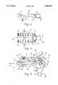
- FIG. 1is a side elevational view of the lateral offset connector of the present invention.
- FIG. 2is a bottom elevational view of the lateral offset connector shown in FIG. 1.
- FIG. 3is an isometric view of the lateral offset connector of the present invention shown engaged between a spinal fixation rod and a bone screw.
- FIGS. 1 and 2A lateral offset connector 10 according to the present invention is illustrated in FIGS. 1 and 2.
- the lateral offset connector 10is preferably formed from medical grade stainless steel or other biocompatible material.
- the connector 10includes a head 11 to which a pair of parallel arms 14 are integrally engaged.
- the armsare formed with a plurality of parallel grooves 17 with lands 18 interspersed between the grooves.
- the grooves 17are aligned between each of the arms 14, perpendicular to the longitudinal axis L of the arm 14.
- the grooves 17are uniformly spaced relative to each other along the longitudinal axis L.
- the arms 14are disposed apart from each other to define a slot opening 20 therebetween.
- the head 11 of the lateral offset connector 10includes a rounded shoulder 25.
- a guide portion 27is formed along the longitudinal axis L of the offset connector and includes a threaded post 30 extending therefrom.
- the guide portion 27is rectangular in cross-section and projects slightly out from the surface of the rounded shoulder 25, as shown more clearly in FIG. 2.
- the lateral offset connector 10is adapted to be engaged to a spinal rod 40, as depicted in FIG. 3. More particularly, the rod 40 is situated within a pair of grooves 17 aligned between the arms 14.
- the groovesare formed at a radius of 0.094 inches (2.4 mm) to accommodate standard spinal rods of 0.188 inch (4.78 mm) or inch (6.35 mm) diameter. As appears in FIG. 1, the grooves are cut so to form an arc less than a complete semi-circle. Thus, even the larger spinal rod 0.250 inch diameter) can be accepted within the groove radius of the specific embodiment.
- the groovesmust span enough of an arc to adequately retain the rod 40 within the groove 17 to restrain the offset connector 10 from lateral movement relative to the rod.
- the slot opening 20provides space for engagement of an eyebolt 45 between the arms 14.
- the eyebolt 45defines a bore 46 through which the spinal rod 40 extends.
- the eyebolt 45also includes a threaded post 47 extending from the eyebolt onto which a locknut 48 can be engaged.
- the eyebolt 45can preferably be a 1/4 inch eyebolt/locknut assembly provided by Danek Medical, Inc. as part number 808-029 for use with the Danek TSRH spinal implant system.
- the eyebolt 45is situated between the pair of parallel arms 14 with the spinal fixation rod 40 extending through the bore 46. With the arms 14 straddling the eyebolt 45 the rod 40 is situated within an aligned pair of grooves 17.
- the eyebolt 45is situated within the slot opening 20 of the connector so that the threaded post 47 extends upward through the slot opening 20.
- the locknut 48is then threaded onto the threaded post 47 until it contacts the upper face 15 of the pair of arms 14. As the locknut 48 is tightened onto the threaded post 47, it pushes the arms 14 downward so that the spinal rod 40 is clamped between the eyebolt bore 46 and the grooves 17 on the pair of arms 14, in the manner of a three-point shear clamp.
- the slot opening 20is 0.255 inches (6.48 mm) wide and 0.938 inches (23.83 mm) deep to accommodate a standard eyebolt, such as the Danek eyebolt No. 808-029.
- the bone screw 50includes a threaded shaft 51 for engaging the pedicle of a vertebrae, for instance, and a head portion 52 which is configured to form a yoke 53.
- the bone screw 50is connected to the offset connector 10 with the yoke 53 contacting the rounded shoulder 25 of the head portion 11.
- the guide portion 27extends between the arms of the yoke 53 of the bone screw 50 to properly orient the bone screw 50.
- the rectangular configuration of the guide portion 27engages the arms of the yoke 53 so that the bone screw 50 is restrained from twisting about the longitudinal axis L of the offset connector 10. Any such twisting moment is transmitted directly through the guide portion 27 and arms 14 of the offset connector 10 to be reacted by the spinal rod 40.
- a nut 32is threaded onto the threaded post 30 extending from the offset connector 10 to firmly engage the head 52 of the bone screw 50 between the nut 32 and the rounded shoulder 25.
- the threaded post 30is preferably dimensioned to emulate a standard eyebolt (such as the Danek 808-029 eyebolt), so that no modification of the design of the bone screw is required.
- the rounded shoulder 25is provided so that the bone screw 50 can be engaged to the offset connector 10 at orientations other than perpendicular to the connector axis L, as may be required by the local geometry of the vertebral column. In one specific embodiment, the rounded shoulder 25 is formed at a radius of 0.250 inches (6.35 mm).
- the bone screw 50can be a sacral spinal screw provided by Danek Medical as part number 808-225, or other similar screw. It is understood that while the bone screw 50 in the preferred embodiment is described as having an open yoke configuration for the head of the screw, a closed head bone screw can also be utilized provided that there is an opening through which the threaded post 30 can extend. It is, however, preferable to use an open yoke configured bone screw so that the bone screw 50 can be threaded into the vertebrae and the offset connector 10 subsequently fixed between the bone screw and the fixation rod 40.
- the spinal rod 40 and the bone screw 50will already be in position relative to the vertebral column of the patient. It is therefore critical that the connection between the bone screw 50 and spinal rod 40 have some means to account for differences in the lateral distance between these two components. While prior devices required bending or contouring of the spinal rod 40 in the saggital plane so that it is close to the bone screw, the present invention provides a connector which can accommodate a wide range of lateral distances between the bone screw and the spinal rod. Specifically, the lateral offset connector connector 10 can be moved back and forth between the bone screw 50 and the fixation rod 40, as shown by the arrow A in FIG. 3, to adjust to the lateral distance between these two components.
- the rod 40be engaged within an appropriate pair of grooves 17 when the offset connector 10 is engaged to the bone screw 50.
- five such grooves 17are provided at 0.162 inch (4.11 mm) intervals. It has been found that this arrangement of grooves accommodates most abnormal curvature conditions.
- an offset connectorcan be provided with longer legs 14 having more grooves to account for greater lateral distances between the spinal rod 40 and the vertebral fixation element 50.
- the eyebolt 45to clamp the offset connector 10 to the rod 40 also permits adjustment of the connector along the longitudinal length of the spinal rod. This feature is important when the offset connector 10 is first engaged to a bone screw 50 which is already threaded into a vertebra. With the eyebolt 45 freely sliding along the spinal rod 40, the position of the offset connector 10 can be oriented so that the guide portion 27 is aligned with the yoke 53 of the bone screw 50. The connector 10 can then be moved laterally until the guide portion 27 slides within the yoke 53. At this point, the two nuts 32 and 48 can be tightened to rigidly connect the bone screw 50 to the spinal rod 40.
- lateral offset connector 10is configured for connecting a bone screw 50 to the spinal rod 40
- other vertebral fixation elementsare contemplated.
- a pedicle hookcan also be engaged to the threaded post 30 of the connector, such as the Danek pedicle halftop hook, provided as part number 808-005 or the Danek large laminar halftop hook part number 808-008.
Landscapes
- Health & Medical Sciences (AREA)
- Orthopedic Medicine & Surgery (AREA)
- Life Sciences & Earth Sciences (AREA)
- Neurology (AREA)
- Surgery (AREA)
- Heart & Thoracic Surgery (AREA)
- Engineering & Computer Science (AREA)
- Biomedical Technology (AREA)
- Nuclear Medicine, Radiotherapy & Molecular Imaging (AREA)
- Medical Informatics (AREA)
- Molecular Biology (AREA)
- Animal Behavior & Ethology (AREA)
- General Health & Medical Sciences (AREA)
- Public Health (AREA)
- Veterinary Medicine (AREA)
- Surgical Instruments (AREA)
- Prostheses (AREA)
Abstract
Description
Claims (4)
Priority Applications (12)
| Application Number | Priority Date | Filing Date | Title |
|---|---|---|---|
| US07/803,325US5209752A (en) | 1991-12-04 | 1991-12-04 | Lateral offset connector for spinal implant system |
| CA002124950ACA2124950A1 (en) | 1991-12-04 | 1992-12-03 | Lateral offset connector for spinal implant system |
| NZ246247ANZ246247A (en) | 1991-12-04 | 1992-12-03 | Spinal implant offset connector with lateral adjustability via parallel arms having aligned arc shaped grooves to receive spinal rod |
| EP93900784AEP0615427A4 (en) | 1991-12-04 | 1992-12-03 | LATERAL OFFSET CONNECTION FOR SPINAL IMPLANT SYSTEM. |
| JP5510332AJPH07501467A (en) | 1991-12-04 | 1992-12-03 | Lateral Offset Connector for Spinal Implant Devices |
| BR9206875ABR9206875A (en) | 1991-12-04 | 1992-12-03 | Lateral displaced connector for spinal implant system |
| AU32345/93AAU658711B2 (en) | 1991-12-04 | 1992-12-03 | Lateral offset connector for spinal implant system |
| PCT/US1992/010403WO1993010717A1 (en) | 1991-12-04 | 1992-12-03 | Lateral offset connector for spinal implant system |
| MX9207025AMX9207025A (en) | 1991-12-04 | 1992-12-04 | SIDE DISPLACEMENT CONNECTOR FOR SPINAL IMPLANT SYSTEM. |
| TW082100171ATW235912B (en) | 1991-12-04 | 1993-01-13 | |
| NO942057ANO942057L (en) | 1991-12-04 | 1994-06-02 | Side displacement connector for spinal implant system |
| FI942612AFI942612A0 (en) | 1991-12-04 | 1994-06-03 | Lateral isolation connector for transplant system |
Applications Claiming Priority (1)
| Application Number | Priority Date | Filing Date | Title |
|---|---|---|---|
| US07/803,325US5209752A (en) | 1991-12-04 | 1991-12-04 | Lateral offset connector for spinal implant system |
Publications (1)
| Publication Number | Publication Date |
|---|---|
| US5209752Atrue US5209752A (en) | 1993-05-11 |
Family
ID=25186240
Family Applications (1)
| Application Number | Title | Priority Date | Filing Date |
|---|---|---|---|
| US07/803,325Expired - LifetimeUS5209752A (en) | 1991-12-04 | 1991-12-04 | Lateral offset connector for spinal implant system |
Country Status (11)
| Country | Link |
|---|---|
| US (1) | US5209752A (en) |
| EP (1) | EP0615427A4 (en) |
| JP (1) | JPH07501467A (en) |
| AU (1) | AU658711B2 (en) |
| BR (1) | BR9206875A (en) |
| CA (1) | CA2124950A1 (en) |
| FI (1) | FI942612A0 (en) |
| MX (1) | MX9207025A (en) |
| NZ (1) | NZ246247A (en) |
| TW (1) | TW235912B (en) |
| WO (1) | WO1993010717A1 (en) |
Cited By (71)
| Publication number | Priority date | Publication date | Assignee | Title |
|---|---|---|---|---|
| US5282801A (en)* | 1993-02-17 | 1994-02-01 | Danek Medical, Inc. | Top tightening clamp assembly for a spinal fixation system |
| WO1994008530A1 (en)* | 1992-10-22 | 1994-04-28 | Danek Medical, Inc. | Spinal rod transverse connector for supporting vertebral fixation elements |
| WO1994015554A1 (en)* | 1993-01-04 | 1994-07-21 | Danek Medical, Inc. | Spinal fixation system |
| US5423818A (en)* | 1993-02-17 | 1995-06-13 | Danek Medical, Inc. | Clamp for attaching a vertebral fixation element to a spinal rod |
| FR2720261A1 (en)* | 1994-05-27 | 1995-12-01 | Pascal Aufaure | Osteosynthesis device implant |
| US5499983A (en)* | 1994-02-23 | 1996-03-19 | Smith & Nephew Richards, Inc. | Variable angle spinal screw |
| US5545228A (en)* | 1991-08-15 | 1996-08-13 | Smith & Nephew Richards Inc. | Offset bone bolt |
| US5545164A (en)* | 1992-12-28 | 1996-08-13 | Advanced Spine Fixation Systems, Incorporated | Occipital clamp assembly for cervical spine rod fixation |
| US5545167A (en)* | 1995-04-11 | 1996-08-13 | Lin; Chih-I | Retaining mechanism of vertebral fixation rod |
| US5611800A (en)* | 1994-02-15 | 1997-03-18 | Alphatec Manufacturing, Inc. | Spinal fixation system |
| US5653708A (en)* | 1992-12-28 | 1997-08-05 | Advanced Spine Fixation Systems, Inc. | Cervical spine rod fixation system |
| US5688272A (en)* | 1995-03-30 | 1997-11-18 | Danek Medical, Inc. | Top-tightening transverse connector for a spinal fixation system |
| EP0878171A1 (en) | 1997-05-15 | 1998-11-18 | Surgical Dynamics, Inc. | Clamping connnector for spinal fixation systems |
| US20040092934A1 (en)* | 2002-04-24 | 2004-05-13 | Howland Robert S. | Multi selective axis spinal fixation system |
| RU2231327C2 (en)* | 2001-10-18 | 2004-06-27 | Матюшин Александр Федорович | Device for joining hook and rod |
| US6755830B2 (en) | 2001-07-04 | 2004-06-29 | Sofamor S.N.C. | Connector for a spinal fixation member |
| US6770075B2 (en) | 2001-05-17 | 2004-08-03 | Robert S. Howland | Spinal fixation apparatus with enhanced axial support and methods for use |
| US20040243128A1 (en)* | 2001-05-17 | 2004-12-02 | Howland Robert S. | Selective axis posterior lumbar spinal plating fixation apparatus and methods for use |
| US6872208B1 (en) | 2000-10-06 | 2005-03-29 | Spinal Concepts, Inc. | Adjustable transverse connector |
| US20050080416A1 (en)* | 2003-10-09 | 2005-04-14 | Ryan Christopher J. | Linking transconnector for coupling spinal rods |
| US6887241B1 (en) | 2000-10-06 | 2005-05-03 | Spinal Concepts, Inc. | Adjustable transverse connector with cam activated engagers |
| US20050101956A1 (en)* | 2003-11-10 | 2005-05-12 | Simonson Peter M. | Artificial facet joint and method |
| US20050101953A1 (en)* | 2003-11-10 | 2005-05-12 | Simonson Peter M. | Artificial facet joint and method |
| US20050240185A1 (en)* | 2004-04-23 | 2005-10-27 | Depuy Spine Sarl | Spinal fixation plates and plate extensions |
| US20050240181A1 (en)* | 2004-04-23 | 2005-10-27 | Boomer Mark C | Spinal implant connectors |
| USRE39035E1 (en) | 1994-11-18 | 2006-03-21 | Howmedica Osteonics Corp. | Universal coupler for spinal fixation |
| US20060064092A1 (en)* | 2001-05-17 | 2006-03-23 | Howland Robert S | Selective axis serrated rod low profile spinal fixation system |
| US20080177323A1 (en)* | 2006-10-18 | 2008-07-24 | Null William B | Orthopedic revision connector |
| US20090005817A1 (en)* | 2007-04-30 | 2009-01-01 | Adam Friedrich | Flexible Spine Stabilization System |
| US7485132B1 (en) | 2000-10-06 | 2009-02-03 | Abbott Spine Inc. | Transverse connector with cam activated engagers |
| US20090076550A1 (en)* | 2007-09-18 | 2009-03-19 | Ortho Development Corporation | Spinal fixation system connectors |
| US20090326592A1 (en)* | 2008-06-27 | 2009-12-31 | Butler Michael S | Posterior Spinal Prosthesis |
| US20100049252A1 (en)* | 2008-08-21 | 2010-02-25 | Southern Spine, Llc | Transverse Connector Device for Extending an Existing Spinal Fixation System |
| US7708764B2 (en) | 2003-11-10 | 2010-05-04 | Simonson Peter M | Method for creating an artificial facet |
| US20100198262A1 (en)* | 2009-01-30 | 2010-08-05 | Mckinley Laurence M | Axial offset bone fastener system |
| US20100256683A1 (en)* | 2009-04-01 | 2010-10-07 | Andrew Iott | Orthopedic Clamp and Extension Rod |
| US20100280622A1 (en)* | 2004-09-14 | 2010-11-04 | Aeolin, Llc | System and method for spinal fusion |
| WO2011053703A2 (en) | 2009-10-30 | 2011-05-05 | Warsaw Orthopedic, Inc. | Apparatus for implementing a spinal fixation system with supplemental fixation |
| US8114158B2 (en) | 2004-08-03 | 2012-02-14 | Kspine, Inc. | Facet device and method |
| US8162979B2 (en) | 2007-06-06 | 2012-04-24 | K Spine, Inc. | Medical device and method to correct deformity |
| US8277489B2 (en) | 2006-09-26 | 2012-10-02 | Synthes Usa, Llc | Transconnector |
| US8357182B2 (en) | 2009-03-26 | 2013-01-22 | Kspine, Inc. | Alignment system with longitudinal support features |
| US20130184760A1 (en)* | 2012-01-12 | 2013-07-18 | Warsaw Orthopedic, Inc | Side loading coronal spinning lateral connector and method |
| US8506598B1 (en)* | 2009-06-26 | 2013-08-13 | Nuvasive, Inc. | Anchors for spinal fixation and correcting spinal deformity |
| US20130211457A1 (en)* | 2012-02-10 | 2013-08-15 | Warsaw Orthopedic, Inc. | Vertebral implant and connector |
| US8828058B2 (en) | 2008-11-11 | 2014-09-09 | Kspine, Inc. | Growth directed vertebral fixation system with distractible connector(s) and apical control |
| US8876869B1 (en) | 2009-06-19 | 2014-11-04 | Nuvasive, Inc. | Polyaxial bone screw assembly |
| US8920472B2 (en) | 2011-11-16 | 2014-12-30 | Kspine, Inc. | Spinal correction and secondary stabilization |
| US9060813B1 (en) | 2008-02-29 | 2015-06-23 | Nuvasive, Inc. | Surgical fixation system and related methods |
| US9168071B2 (en) | 2009-09-15 | 2015-10-27 | K2M, Inc. | Growth modulation system |
| US9179940B2 (en) | 2005-12-06 | 2015-11-10 | Globus Medical, Inc. | System and method for replacement of spinal motion segment |
| US9198692B1 (en) | 2011-02-10 | 2015-12-01 | Nuvasive, Inc. | Spinal fixation anchor |
| US9333009B2 (en) | 2011-06-03 | 2016-05-10 | K2M, Inc. | Spinal correction system actuators |
| US9387013B1 (en) | 2011-03-01 | 2016-07-12 | Nuvasive, Inc. | Posterior cervical fixation system |
| US9451987B2 (en) | 2011-11-16 | 2016-09-27 | K2M, Inc. | System and method for spinal correction |
| US9468471B2 (en) | 2013-09-17 | 2016-10-18 | K2M, Inc. | Transverse coupler adjuster spinal correction systems and methods |
| US9468469B2 (en) | 2011-11-16 | 2016-10-18 | K2M, Inc. | Transverse coupler adjuster spinal correction systems and methods |
| US9468468B2 (en) | 2011-11-16 | 2016-10-18 | K2M, Inc. | Transverse connector for spinal stabilization system |
| US9517089B1 (en) | 2013-10-08 | 2016-12-13 | Nuvasive, Inc. | Bone anchor with offset rod connector |
| US10413365B1 (en) | 2013-10-18 | 2019-09-17 | Medicrea International | Methods, systems, and devices for designing and manufacturing a spinal rod |
| US10702311B2 (en) | 2011-11-16 | 2020-07-07 | K2M, Inc. | Spinal correction and secondary stabilization |
| US10918422B2 (en) | 2017-12-01 | 2021-02-16 | Medicrea International | Method and apparatus for inhibiting proximal junctional failure |
| US10970426B2 (en) | 2013-09-18 | 2021-04-06 | Medicrea International SA | Methods, systems, and devices for designing and manufacturing a spinal rod |
| US11185369B2 (en) | 2017-04-21 | 2021-11-30 | Medicrea Nternational | Systems, methods, and devices for developing patient-specific spinal treatments, operations, and procedures |
| US11612436B2 (en) | 2016-12-12 | 2023-03-28 | Medicrea International | Systems, methods, and devices for developing patient-specific medical treatments, operations, and procedures |
| US11769251B2 (en) | 2019-12-26 | 2023-09-26 | Medicrea International | Systems and methods for medical image analysis |
| US11877801B2 (en) | 2019-04-02 | 2024-01-23 | Medicrea International | Systems, methods, and devices for developing patient-specific spinal implants, treatments, operations, and/or procedures |
| US11925417B2 (en) | 2019-04-02 | 2024-03-12 | Medicrea International | Systems, methods, and devices for developing patient-specific spinal implants, treatments, operations, and/or procedures |
| US12114899B2 (en) | 2022-06-23 | 2024-10-15 | Warsaw Orthopedic, Inc. | Spinal implant and method |
| US12274511B2 (en) | 2019-04-02 | 2025-04-15 | Medicrea International | Systems and methods for medical image analysis |
| US12318144B2 (en) | 2021-06-23 | 2025-06-03 | Medicrea International SA | Systems and methods for planning a patient-specific spinal correction |
Families Citing this family (1)
| Publication number | Priority date | Publication date | Assignee | Title |
|---|---|---|---|---|
| DE29600784U1 (en)* | 1996-01-18 | 1996-03-21 | Howmedica GmbH, 24232 Schönkirchen | Connecting element for a stabilization system for a human spine |
Citations (8)
| Publication number | Priority date | Publication date | Assignee | Title |
|---|---|---|---|---|
| US4448191A (en)* | 1981-07-07 | 1984-05-15 | Rodnyansky Lazar I | Implantable correctant of a spinal curvature and a method for treatment of a spinal curvature |
| US4653481A (en)* | 1985-07-24 | 1987-03-31 | Howland Robert S | Advanced spine fixation system and method |
| US4655199A (en)* | 1985-03-29 | 1987-04-07 | Acromed Corporation | Spinal column straightening apparatus |
| US4719905A (en)* | 1985-11-01 | 1988-01-19 | Acromed Corporation | Apparatus and method for maintaining vertebrae in a desired relationship |
| US4771767A (en)* | 1986-02-03 | 1988-09-20 | Acromed Corporation | Apparatus and method for maintaining vertebrae in a desired relationship |
| US5002542A (en)* | 1989-10-30 | 1991-03-26 | Synthes U.S.A. | Pedicle screw clamp |
| US5084049A (en)* | 1989-02-08 | 1992-01-28 | Acromed Corporation | Transverse connector for spinal column corrective devices |
| US5102412A (en)* | 1990-06-19 | 1992-04-07 | Chaim Rogozinski | System for instrumentation of the spine in the treatment of spinal deformities |
Family Cites Families (2)
| Publication number | Priority date | Publication date | Assignee | Title |
|---|---|---|---|---|
| US5127912A (en)* | 1990-10-05 | 1992-07-07 | R. Charles Ray | Sacral implant system |
| US5261909A (en)* | 1992-02-18 | 1993-11-16 | Danek Medical, Inc. | Variable angle screw for spinal implant system |
- 1991
- 1991-12-04USUS07/803,325patent/US5209752A/ennot_activeExpired - Lifetime
- 1992
- 1992-12-03BRBR9206875Apatent/BR9206875A/enactiveSearch and Examination
- 1992-12-03AUAU32345/93Apatent/AU658711B2/ennot_activeCeased
- 1992-12-03EPEP93900784Apatent/EP0615427A4/ennot_activeCeased
- 1992-12-03JPJP5510332Apatent/JPH07501467A/enactivePending
- 1992-12-03NZNZ246247Apatent/NZ246247A/enunknown
- 1992-12-03WOPCT/US1992/010403patent/WO1993010717A1/ennot_activeApplication Discontinuation
- 1992-12-03CACA002124950Apatent/CA2124950A1/ennot_activeAbandoned
- 1992-12-04MXMX9207025Apatent/MX9207025A/enunknown
- 1993
- 1993-01-13TWTW082100171Apatent/TW235912B/zhactive
- 1994
- 1994-06-03FIFI942612Apatent/FI942612A0/ennot_activeApplication Discontinuation
Patent Citations (9)
| Publication number | Priority date | Publication date | Assignee | Title |
|---|---|---|---|---|
| US4448191A (en)* | 1981-07-07 | 1984-05-15 | Rodnyansky Lazar I | Implantable correctant of a spinal curvature and a method for treatment of a spinal curvature |
| US4655199A (en)* | 1985-03-29 | 1987-04-07 | Acromed Corporation | Spinal column straightening apparatus |
| US4653481A (en)* | 1985-07-24 | 1987-03-31 | Howland Robert S | Advanced spine fixation system and method |
| US4719905A (en)* | 1985-11-01 | 1988-01-19 | Acromed Corporation | Apparatus and method for maintaining vertebrae in a desired relationship |
| US4719905B1 (en)* | 1985-11-01 | 1995-10-31 | Acromed Corp | Apparatus and method for maintaining vertebrae in a desired relationship |
| US4771767A (en)* | 1986-02-03 | 1988-09-20 | Acromed Corporation | Apparatus and method for maintaining vertebrae in a desired relationship |
| US5084049A (en)* | 1989-02-08 | 1992-01-28 | Acromed Corporation | Transverse connector for spinal column corrective devices |
| US5002542A (en)* | 1989-10-30 | 1991-03-26 | Synthes U.S.A. | Pedicle screw clamp |
| US5102412A (en)* | 1990-06-19 | 1992-04-07 | Chaim Rogozinski | System for instrumentation of the spine in the treatment of spinal deformities |
Non-Patent Citations (2)
| Title |
|---|
| TSRH Lumbar System, by Danek Medical, Inc.* |
| TSRH Spinal Implant System, Surgical Technique Manual, copyright 1990 by Danek Medical, Inc.* |
Cited By (157)
| Publication number | Priority date | Publication date | Assignee | Title |
|---|---|---|---|---|
| US5545228A (en)* | 1991-08-15 | 1996-08-13 | Smith & Nephew Richards Inc. | Offset bone bolt |
| US5667506A (en)* | 1992-10-22 | 1997-09-16 | Danek Medical, Inc. | Spinal rod transverse connector for supporting vertebral fixation elements |
| WO1994008530A1 (en)* | 1992-10-22 | 1994-04-28 | Danek Medical, Inc. | Spinal rod transverse connector for supporting vertebral fixation elements |
| US5545164A (en)* | 1992-12-28 | 1996-08-13 | Advanced Spine Fixation Systems, Incorporated | Occipital clamp assembly for cervical spine rod fixation |
| US5653708A (en)* | 1992-12-28 | 1997-08-05 | Advanced Spine Fixation Systems, Inc. | Cervical spine rod fixation system |
| US5534002A (en)* | 1993-01-04 | 1996-07-09 | Danek Medical, Inc. | Spinal fixation system |
| US5527314A (en)* | 1993-01-04 | 1996-06-18 | Danek Medical, Inc. | Spinal fixation system |
| WO1994015554A1 (en)* | 1993-01-04 | 1994-07-21 | Danek Medical, Inc. | Spinal fixation system |
| US5562662A (en)* | 1993-01-04 | 1996-10-08 | Danek Medical Inc. | Spinal fixation system and method |
| US5609592A (en)* | 1993-01-04 | 1997-03-11 | Danek Medical, Inc. | Spinal Fixation System |
| US5282801A (en)* | 1993-02-17 | 1994-02-01 | Danek Medical, Inc. | Top tightening clamp assembly for a spinal fixation system |
| US5423818A (en)* | 1993-02-17 | 1995-06-13 | Danek Medical, Inc. | Clamp for attaching a vertebral fixation element to a spinal rod |
| WO1994018917A1 (en)* | 1993-02-17 | 1994-09-01 | Danek Medical, Inc. | Clamp assembly for a spinal fixation system |
| AU677821B2 (en)* | 1993-02-17 | 1997-05-08 | Warsaw Orthopedic, Inc. | Clamp assembly for a spinal fixation system |
| US5611800A (en)* | 1994-02-15 | 1997-03-18 | Alphatec Manufacturing, Inc. | Spinal fixation system |
| US5499983A (en)* | 1994-02-23 | 1996-03-19 | Smith & Nephew Richards, Inc. | Variable angle spinal screw |
| WO1995032676A1 (en)* | 1994-05-27 | 1995-12-07 | Pascal Aufaure | Implant for an osteosynthesis device |
| FR2720261A1 (en)* | 1994-05-27 | 1995-12-01 | Pascal Aufaure | Osteosynthesis device implant |
| USRE39035E1 (en) | 1994-11-18 | 2006-03-21 | Howmedica Osteonics Corp. | Universal coupler for spinal fixation |
| US5688272A (en)* | 1995-03-30 | 1997-11-18 | Danek Medical, Inc. | Top-tightening transverse connector for a spinal fixation system |
| US5980521A (en)* | 1995-03-30 | 1999-11-09 | Sdgi Holdings,Inc. | Top-tightening transverse connector for a spinal fixation system |
| US5545167A (en)* | 1995-04-11 | 1996-08-13 | Lin; Chih-I | Retaining mechanism of vertebral fixation rod |
| US6413257B1 (en) | 1997-05-15 | 2002-07-02 | Surgical Dynamics, Inc. | Clamping connector for spinal fixation systems |
| US6706045B2 (en) | 1997-05-15 | 2004-03-16 | Howmedica Osteonics Corp. | Clamping connector for spinal fixation systems |
| EP0878171A1 (en) | 1997-05-15 | 1998-11-18 | Surgical Dynamics, Inc. | Clamping connnector for spinal fixation systems |
| US20090138047A1 (en)* | 2000-10-06 | 2009-05-28 | Abbott Spine, Inc. | Transverse connector with cam activated engagers |
| US7485132B1 (en) | 2000-10-06 | 2009-02-03 | Abbott Spine Inc. | Transverse connector with cam activated engagers |
| US8062338B2 (en) | 2000-10-06 | 2011-11-22 | Zimmer Spine, Inc. | Transverse connector with cam activated engagers |
| US6887241B1 (en) | 2000-10-06 | 2005-05-03 | Spinal Concepts, Inc. | Adjustable transverse connector with cam activated engagers |
| US6872208B1 (en) | 2000-10-06 | 2005-03-29 | Spinal Concepts, Inc. | Adjustable transverse connector |
| US6770075B2 (en) | 2001-05-17 | 2004-08-03 | Robert S. Howland | Spinal fixation apparatus with enhanced axial support and methods for use |
| US20050216005A1 (en)* | 2001-05-17 | 2005-09-29 | Howland Robert S | Selective axis anchor screw posterior lumbar plating system |
| US20060064092A1 (en)* | 2001-05-17 | 2006-03-23 | Howland Robert S | Selective axis serrated rod low profile spinal fixation system |
| US20040243128A1 (en)* | 2001-05-17 | 2004-12-02 | Howland Robert S. | Selective axis posterior lumbar spinal plating fixation apparatus and methods for use |
| US6755830B2 (en) | 2001-07-04 | 2004-06-29 | Sofamor S.N.C. | Connector for a spinal fixation member |
| RU2231327C2 (en)* | 2001-10-18 | 2004-06-27 | Матюшин Александр Федорович | Device for joining hook and rod |
| US20040092934A1 (en)* | 2002-04-24 | 2004-05-13 | Howland Robert S. | Multi selective axis spinal fixation system |
| US7314467B2 (en) | 2002-04-24 | 2008-01-01 | Medical Device Advisory Development Group, Llc. | Multi selective axis spinal fixation system |
| US7481827B2 (en)* | 2003-10-09 | 2009-01-27 | Synthes (U.S.A.) | Linking transconnector for coupling spinal rods |
| KR101154204B1 (en) | 2003-10-09 | 2012-06-18 | 신세스 게엠바하 | Linking transconnector for coupling spinal rods |
| US20050080416A1 (en)* | 2003-10-09 | 2005-04-14 | Ryan Christopher J. | Linking transconnector for coupling spinal rods |
| US7708764B2 (en) | 2003-11-10 | 2010-05-04 | Simonson Peter M | Method for creating an artificial facet |
| US8142478B2 (en) | 2003-11-10 | 2012-03-27 | Simonson Peter M | Artificial facet joint and method |
| US7083622B2 (en) | 2003-11-10 | 2006-08-01 | Simonson Peter M | Artificial facet joint and method |
| US20080262545A1 (en)* | 2003-11-10 | 2008-10-23 | Simonson Peter M | Artificial Facet Joint and Method |
| US20050101956A1 (en)* | 2003-11-10 | 2005-05-12 | Simonson Peter M. | Artificial facet joint and method |
| US20090216279A1 (en)* | 2003-11-10 | 2009-08-27 | Simonson Peter M | Artificial facet joint and method |
| US20050101953A1 (en)* | 2003-11-10 | 2005-05-12 | Simonson Peter M. | Artificial facet joint and method |
| US20050240185A1 (en)* | 2004-04-23 | 2005-10-27 | Depuy Spine Sarl | Spinal fixation plates and plate extensions |
| US20050240181A1 (en)* | 2004-04-23 | 2005-10-27 | Boomer Mark C | Spinal implant connectors |
| US7572282B2 (en) | 2004-04-23 | 2009-08-11 | Depuy Spine Sarl | Spinal fixation plates and plate extensions |
| US20100010541A1 (en)* | 2004-04-23 | 2010-01-14 | Depuy Spine Sarl | Spinal fixation plates and plate extensions |
| US8728080B2 (en) | 2004-04-23 | 2014-05-20 | Depuy Spine Sarl | Spinal fixation plates and plate extensions |
| US9011491B2 (en) | 2004-08-03 | 2015-04-21 | K Spine, Inc. | Facet device and method |
| US9451997B2 (en) | 2004-08-03 | 2016-09-27 | K2M, Inc. | Facet device and method |
| US8114158B2 (en) | 2004-08-03 | 2012-02-14 | Kspine, Inc. | Facet device and method |
| US8562683B2 (en) | 2004-09-14 | 2013-10-22 | Aeolin Llc | System and method for spinal fusion |
| US20100280622A1 (en)* | 2004-09-14 | 2010-11-04 | Aeolin, Llc | System and method for spinal fusion |
| US9179940B2 (en) | 2005-12-06 | 2015-11-10 | Globus Medical, Inc. | System and method for replacement of spinal motion segment |
| US8784452B2 (en) | 2006-09-26 | 2014-07-22 | DePuy Synthes Products, LLC | Transconnector |
| US8277489B2 (en) | 2006-09-26 | 2012-10-02 | Synthes Usa, Llc | Transconnector |
| US20080177323A1 (en)* | 2006-10-18 | 2008-07-24 | Null William B | Orthopedic revision connector |
| US20110190828A1 (en)* | 2006-10-18 | 2011-08-04 | Warsaw Orthopedic, Inc | Orthopedic revision connector |
| US8298269B2 (en) | 2006-10-18 | 2012-10-30 | Warsaw Orthopedic, Inc. | Orthopedic revision connector |
| US7976567B2 (en) | 2006-10-18 | 2011-07-12 | Warsaw Orthopedic, Inc. | Orthopedic revision connector |
| US9339297B2 (en) | 2007-04-30 | 2016-05-17 | Globus Medical, Inc. | Flexible spine stabilization system |
| US9220538B2 (en) | 2007-04-30 | 2015-12-29 | Globus Medical, Inc. | Flexible element for spine stabilization system |
| US20090005817A1 (en)* | 2007-04-30 | 2009-01-01 | Adam Friedrich | Flexible Spine Stabilization System |
| US9211142B2 (en) | 2007-04-30 | 2015-12-15 | Globus Medical, Inc. | Flexible element for spine stabilization system |
| US8465526B2 (en) | 2007-04-30 | 2013-06-18 | Globus Medical, Inc. | Flexible spine stabilization system |
| US10426523B2 (en) | 2007-06-06 | 2019-10-01 | K2M, Inc. | Medical device and method to correct deformity |
| US9848917B2 (en) | 2007-06-06 | 2017-12-26 | K2M, Inc. | Medical device and method to correct deformity |
| US8162979B2 (en) | 2007-06-06 | 2012-04-24 | K Spine, Inc. | Medical device and method to correct deformity |
| US11246628B2 (en) | 2007-06-06 | 2022-02-15 | K2M, Inc. | Medical device and method to correct deformity |
| US12262922B2 (en) | 2007-06-06 | 2025-04-01 | K2M, Inc. | Medical device and method to correct deformity |
| US20090076550A1 (en)* | 2007-09-18 | 2009-03-19 | Ortho Development Corporation | Spinal fixation system connectors |
| US9060813B1 (en) | 2008-02-29 | 2015-06-23 | Nuvasive, Inc. | Surgical fixation system and related methods |
| US8663295B2 (en)* | 2008-06-27 | 2014-03-04 | Life Spine, Inc. | Posterior spinal prosthesis |
| US20090326592A1 (en)* | 2008-06-27 | 2009-12-31 | Butler Michael S | Posterior Spinal Prosthesis |
| US9149303B2 (en) | 2008-06-27 | 2015-10-06 | Life Spine, Inc. | Posterior spinal prosthesis |
| US20100049252A1 (en)* | 2008-08-21 | 2010-02-25 | Southern Spine, Llc | Transverse Connector Device for Extending an Existing Spinal Fixation System |
| US8828058B2 (en) | 2008-11-11 | 2014-09-09 | Kspine, Inc. | Growth directed vertebral fixation system with distractible connector(s) and apical control |
| US9510865B2 (en) | 2008-11-11 | 2016-12-06 | K2M, Inc. | Growth directed vertebral fixation system with distractible connector(s) and apical control |
| US10842536B2 (en) | 2008-11-11 | 2020-11-24 | K2M, Inc. | Growth directed vertebral fixation system with distractible connector(s) and apical control |
| US20100198262A1 (en)* | 2009-01-30 | 2010-08-05 | Mckinley Laurence M | Axial offset bone fastener system |
| US8518086B2 (en) | 2009-03-26 | 2013-08-27 | K Spine, Inc. | Semi-constrained anchoring system |
| US8357183B2 (en) | 2009-03-26 | 2013-01-22 | Kspine, Inc. | Semi-constrained anchoring system |
| US12137943B2 (en) | 2009-03-26 | 2024-11-12 | K2M, Inc. | Semi-constrained anchoring system |
| US8357182B2 (en) | 2009-03-26 | 2013-01-22 | Kspine, Inc. | Alignment system with longitudinal support features |
| US11154329B2 (en) | 2009-03-26 | 2021-10-26 | K2M, Inc. | Semi-constrained anchoring system |
| US9173681B2 (en) | 2009-03-26 | 2015-11-03 | K2M, Inc. | Alignment system with longitudinal support features |
| US9358044B2 (en) | 2009-03-26 | 2016-06-07 | K2M, Inc. | Semi-constrained anchoring system |
| US11564717B2 (en) | 2009-04-01 | 2023-01-31 | Globus Medical, Inc. | Orthopedic clamp and extension rod |
| US10595909B2 (en) | 2009-04-01 | 2020-03-24 | Globus Medical, Inc. | Orthopedic clamp and extension rod |
| US9808293B2 (en) | 2009-04-01 | 2017-11-07 | Globus Medical, Inc. | Orthopedic clamp and extension rod |
| US9283003B2 (en) | 2009-04-01 | 2016-03-15 | Globus Medical, Inc. | Orthopedic clamp and extension rod |
| US20100256683A1 (en)* | 2009-04-01 | 2010-10-07 | Andrew Iott | Orthopedic Clamp and Extension Rod |
| US12193713B2 (en) | 2009-04-01 | 2025-01-14 | Globus Medical, Inc. | Orthopedic clamp and extension rod |
| US8882803B2 (en)* | 2009-04-01 | 2014-11-11 | Globus Medical, Inc. | Orthopedic clamp and extension rod |
| US8876869B1 (en) | 2009-06-19 | 2014-11-04 | Nuvasive, Inc. | Polyaxial bone screw assembly |
| US8506598B1 (en)* | 2009-06-26 | 2013-08-13 | Nuvasive, Inc. | Anchors for spinal fixation and correcting spinal deformity |
| US9168071B2 (en) | 2009-09-15 | 2015-10-27 | K2M, Inc. | Growth modulation system |
| US10736669B2 (en) | 2009-09-15 | 2020-08-11 | K2M, Inc. | Growth modulation system |
| US9827022B2 (en) | 2009-09-15 | 2017-11-28 | K2M, Llc | Growth modulation system |
| WO2011053703A2 (en) | 2009-10-30 | 2011-05-05 | Warsaw Orthopedic, Inc. | Apparatus for implementing a spinal fixation system with supplemental fixation |
| US20110106164A1 (en)* | 2009-10-30 | 2011-05-05 | Warsaw Othropedic, Inc. | Apparatus for implementing a spinal fixation system with supplemental fixation |
| US8795337B2 (en) | 2009-10-30 | 2014-08-05 | Warsaw Orthopedic, Inc. | Apparatus for implementing a spinal fixation system with supplemental fixation |
| US9198692B1 (en) | 2011-02-10 | 2015-12-01 | Nuvasive, Inc. | Spinal fixation anchor |
| US11123110B2 (en) | 2011-03-01 | 2021-09-21 | Nuvasive, Inc. | Posterior cervical fixation system |
| US9387013B1 (en) | 2011-03-01 | 2016-07-12 | Nuvasive, Inc. | Posterior cervical fixation system |
| US9956009B1 (en) | 2011-03-01 | 2018-05-01 | Nuvasive, Inc. | Posterior cervical fixation system |
| US10368918B2 (en) | 2011-03-01 | 2019-08-06 | Nuvasive, Inc. | Posterior cervical fixation system |
| US9408638B2 (en) | 2011-06-03 | 2016-08-09 | K2M, Inc. | Spinal correction system actuators |
| US9895168B2 (en) | 2011-06-03 | 2018-02-20 | K2M, Inc. | Spinal correction system actuators |
| US10675062B2 (en) | 2011-06-03 | 2020-06-09 | K2M, Inc. | Spinal correction system actuators |
| US9333009B2 (en) | 2011-06-03 | 2016-05-10 | K2M, Inc. | Spinal correction system actuators |
| US9757157B2 (en) | 2011-11-16 | 2017-09-12 | K2M, Inc. | System and method for spinal correction |
| US9468468B2 (en) | 2011-11-16 | 2016-10-18 | K2M, Inc. | Transverse connector for spinal stabilization system |
| US11013538B2 (en) | 2011-11-16 | 2021-05-25 | K2M, Inc. | System and method for spinal correction |
| US10342581B2 (en) | 2011-11-16 | 2019-07-09 | K2M, Inc. | System and method for spinal correction |
| US9113959B2 (en) | 2011-11-16 | 2015-08-25 | K2M, Inc. | Spinal correction and secondary stabilization |
| US8920472B2 (en) | 2011-11-16 | 2014-12-30 | Kspine, Inc. | Spinal correction and secondary stabilization |
| US9451987B2 (en) | 2011-11-16 | 2016-09-27 | K2M, Inc. | System and method for spinal correction |
| US9827017B2 (en) | 2011-11-16 | 2017-11-28 | K2M, Inc. | Spinal correction and secondary stabilization |
| US9468469B2 (en) | 2011-11-16 | 2016-10-18 | K2M, Inc. | Transverse coupler adjuster spinal correction systems and methods |
| US10702311B2 (en) | 2011-11-16 | 2020-07-07 | K2M, Inc. | Spinal correction and secondary stabilization |
| US20130184760A1 (en)* | 2012-01-12 | 2013-07-18 | Warsaw Orthopedic, Inc | Side loading coronal spinning lateral connector and method |
| US9101405B2 (en)* | 2012-02-10 | 2015-08-11 | Warsaw Orthopedic, Inc. | Vertebral implant and connector |
| US20130211457A1 (en)* | 2012-02-10 | 2013-08-15 | Warsaw Orthopedic, Inc. | Vertebral implant and connector |
| US9468471B2 (en) | 2013-09-17 | 2016-10-18 | K2M, Inc. | Transverse coupler adjuster spinal correction systems and methods |
| US12019955B2 (en) | 2013-09-18 | 2024-06-25 | Medicrea International | Method making it possible to produce the ideal curvature of a rod of vertebral osteosynthesis material designed to support a patient's vertebral column |
| US10970426B2 (en) | 2013-09-18 | 2021-04-06 | Medicrea International SA | Methods, systems, and devices for designing and manufacturing a spinal rod |
| US12417323B2 (en) | 2013-09-18 | 2025-09-16 | Medicrea International | Method of making it possible to produce and ideal curvature of a rod of vertebral osteosynthesis material designed to support a patient's vertebral column |
| US9517089B1 (en) | 2013-10-08 | 2016-12-13 | Nuvasive, Inc. | Bone anchor with offset rod connector |
| US11197719B2 (en) | 2013-10-18 | 2021-12-14 | Medicrea International | Methods, systems, and devices for designing and manufacturing a spinal rod |
| US10441363B1 (en) | 2013-10-18 | 2019-10-15 | Medicrea International | Methods, systems, and devices for designing and manufacturing a spinal rod |
| US11197718B2 (en) | 2013-10-18 | 2021-12-14 | Medicrea Iniernational | Methods, systems, and devices for designing and manufacturing a spinal rod |
| US10413365B1 (en) | 2013-10-18 | 2019-09-17 | Medicrea International | Methods, systems, and devices for designing and manufacturing a spinal rod |
| US10973582B2 (en) | 2013-10-18 | 2021-04-13 | Medicrea International | Methods, systems, and devices for designing and manufacturing a spinal rod |
| US10420615B1 (en) | 2013-10-18 | 2019-09-24 | Medicrea International | Methods, systems, and devices for designing and manufacturing a spinal rod |
| US10426553B2 (en) | 2013-10-18 | 2019-10-01 | Medicrea International | Methods, systems, and devices for designing and manufacturing a spinal rod |
| US12257000B2 (en) | 2013-10-18 | 2025-03-25 | Medicrea International | Methods, systems, and devices for designing and manufacturing a spinal rod |
| US10433913B2 (en) | 2013-10-18 | 2019-10-08 | Medicrea International | Methods, systems, and devices for designing and manufacturing a spinal rod |
| US11918295B2 (en) | 2013-10-18 | 2024-03-05 | Medicrea International | Methods, systems, and devices for designing and manufacturing a spinal rod |
| US10433912B1 (en) | 2013-10-18 | 2019-10-08 | Medicrea International | Methods, systems, and devices for designing and manufacturing a spinal rod |
| US11612436B2 (en) | 2016-12-12 | 2023-03-28 | Medicrea International | Systems, methods, and devices for developing patient-specific medical treatments, operations, and procedures |
| US12178516B2 (en) | 2016-12-12 | 2024-12-31 | Medicrea International | Systems, methods, and devices for developing patient-specific medical treatments, operations, and procedures |
| US12004814B2 (en) | 2017-04-21 | 2024-06-11 | Medicrea International | Systems, methods, and devices for developing patient-specific spinal treatments, operations, and procedures |
| US11185369B2 (en) | 2017-04-21 | 2021-11-30 | Medicrea Nternational | Systems, methods, and devices for developing patient-specific spinal treatments, operations, and procedures |
| US10918422B2 (en) | 2017-12-01 | 2021-02-16 | Medicrea International | Method and apparatus for inhibiting proximal junctional failure |
| US11925417B2 (en) | 2019-04-02 | 2024-03-12 | Medicrea International | Systems, methods, and devices for developing patient-specific spinal implants, treatments, operations, and/or procedures |
| US11877801B2 (en) | 2019-04-02 | 2024-01-23 | Medicrea International | Systems, methods, and devices for developing patient-specific spinal implants, treatments, operations, and/or procedures |
| US12251165B2 (en) | 2019-04-02 | 2025-03-18 | Medicrea International | Systems, methods, and devices for developing patient-specific spinal implants, treatments, operations, and/or procedures |
| US12274511B2 (en) | 2019-04-02 | 2025-04-15 | Medicrea International | Systems and methods for medical image analysis |
| US11769251B2 (en) | 2019-12-26 | 2023-09-26 | Medicrea International | Systems and methods for medical image analysis |
| US12318144B2 (en) | 2021-06-23 | 2025-06-03 | Medicrea International SA | Systems and methods for planning a patient-specific spinal correction |
| US12114899B2 (en) | 2022-06-23 | 2024-10-15 | Warsaw Orthopedic, Inc. | Spinal implant and method |
Also Published As
| Publication number | Publication date |
|---|---|
| TW235912B (en) | 1994-12-11 |
| AU3234593A (en) | 1993-06-28 |
| BR9206875A (en) | 1995-11-28 |
| NZ246247A (en) | 1996-08-27 |
| EP0615427A1 (en) | 1994-09-21 |
| WO1993010717A1 (en) | 1993-06-10 |
| FI942612A7 (en) | 1994-06-03 |
| MX9207025A (en) | 1993-07-01 |
| EP0615427A4 (en) | 1995-02-22 |
| JPH07501467A (en) | 1995-02-16 |
| CA2124950A1 (en) | 1993-06-10 |
| FI942612A0 (en) | 1994-06-03 |
| AU658711B2 (en) | 1995-04-27 |
Similar Documents
| Publication | Publication Date | Title |
|---|---|---|
| US5209752A (en) | Lateral offset connector for spinal implant system | |
| US5645544A (en) | Variable angle extension rod | |
| US6030388A (en) | Top tightening bone fixation apparatus | |
| AU680209B2 (en) | Spinal rod transverse connector for supporting vertebral fixation elements | |
| EP0399011B1 (en) | Pedicle engaging means | |
| US5609592A (en) | Spinal Fixation System | |
| JP2506564B2 (en) | Variable angle screw for spinal implant system | |
| US5403316A (en) | Triangular construct for spinal fixation | |
| US7122036B2 (en) | Connector for an osteosynthesis system intended to provide a connection between two rods of a spinal osteosynthesis system, osteosynthesis system using such a connector, and method of implanting such an osteosynthesis system | |
| EP0951247B1 (en) | Multi-angle bone screw assembly using shape-memory technology | |
| EP0934026B1 (en) | Apparatus for spinal fixation | |
| US6706045B2 (en) | Clamping connector for spinal fixation systems | |
| US6132430A (en) | Spinal fixation system | |
| US5976135A (en) | Lateral connector assembly | |
| US20030083659A1 (en) | Transverse rod connector clip | |
| EP2211742A1 (en) | Surgical fixation system and related methods | |
| AU720356C (en) | Multi-angle bone screw assembly using shape-memory technology |
Legal Events
| Date | Code | Title | Description |
|---|---|---|---|
| AS | Assignment | Owner name:DANEK MEDICAL, INC., TENNESSEE Free format text:ASSIGNMENT OF ASSIGNORS INTEREST.;ASSIGNOR:ASHMAN, RICHARD B.;REEL/FRAME:005953/0841 Effective date:19911204 Owner name:DANEK MEDICAL, INC., TENNESSEE Free format text:ASSIGNMENT OF ASSIGNORS INTEREST.;ASSIGNOR:SHERMAN, MICHAEL C.;REEL/FRAME:005953/0843 Effective date:19911210 | |
| STCF | Information on status: patent grant | Free format text:PATENTED CASE | |
| FEPP | Fee payment procedure | Free format text:PAT HLDR NO LONGER CLAIMS SMALL ENT STAT AS INDIV INVENTOR (ORIGINAL EVENT CODE: LSM1); ENTITY STATUS OF PATENT OWNER: LARGE ENTITY Free format text:PAYOR NUMBER ASSIGNED (ORIGINAL EVENT CODE: ASPN); ENTITY STATUS OF PATENT OWNER: LARGE ENTITY | |
| FPAY | Fee payment | Year of fee payment:4 | |
| AS | Assignment | Owner name:SDGI HOLDINGS, INC., DELAWARE Free format text:ASSIGNMENT OF ASSIGNORS INTEREST;ASSIGNOR:DANEK MEDICAL, INC.;REEL/FRAME:008811/0663 Effective date:19970626 | |
| FPAY | Fee payment | Year of fee payment:8 | |
| FPAY | Fee payment | Year of fee payment:12 |