US5209749A - Fluoroscopically alignable cutter assembly and method of using the same - Google Patents
Fluoroscopically alignable cutter assembly and method of using the sameDownload PDFInfo
- Publication number
- US5209749A US5209749AUS07/824,897US82489792AUS5209749AUS 5209749 AUS5209749 AUS 5209749AUS 82489792 AUS82489792 AUS 82489792AUS 5209749 AUS5209749 AUS 5209749A
- Authority
- US
- United States
- Prior art keywords
- support
- cutting element
- radiopaque
- body cavity
- marker pattern
- Prior art date
- Legal status (The legal status is an assumption and is not a legal conclusion. Google has not performed a legal analysis and makes no representation as to the accuracy of the status listed.)
- Expired - Lifetime
Links
- 238000000034methodMethods0.000titleclaimsabstractdescription23
- 239000003550markerSubstances0.000claimsabstractdescription31
- 230000000007visual effectEffects0.000claims14
- 230000003213activating effectEffects0.000claims3
- 230000001747exhibiting effectEffects0.000claims2
- 238000003780insertionMethods0.000claims2
- 230000037431insertionEffects0.000claims2
- 210000001519tissueAnatomy0.000description14
- 238000001356surgical procedureMethods0.000description4
- 230000010339dilationEffects0.000description2
- 238000002594fluoroscopyMethods0.000description2
- 210000003708urethraAnatomy0.000description2
- 208000037260Atherosclerotic PlaqueDiseases0.000description1
- 208000029549Muscle injuryDiseases0.000description1
- 208000028389Nerve injuryDiseases0.000description1
- 230000006978adaptationEffects0.000description1
- 210000001367arteryAnatomy0.000description1
- 201000010099diseaseDiseases0.000description1
- 208000037265diseases, disorders, signs and symptomsDiseases0.000description1
- 208000014674injuryDiseases0.000description1
- 239000000976inkSubstances0.000description1
- 230000009191jumpingEffects0.000description1
- 239000000463materialSubstances0.000description1
- 239000011159matrix materialSubstances0.000description1
- 238000012986modificationMethods0.000description1
- 230000004048modificationEffects0.000description1
- 210000005036nerveAnatomy0.000description1
- 230000000644propagated effectEffects0.000description1
- 210000002307prostateAnatomy0.000description1
- 230000008733traumaEffects0.000description1
- 210000000626ureterAnatomy0.000description1
Images
Classifications
- A—HUMAN NECESSITIES
- A61—MEDICAL OR VETERINARY SCIENCE; HYGIENE
- A61B—DIAGNOSIS; SURGERY; IDENTIFICATION
- A61B17/00—Surgical instruments, devices or methods
- A61B17/32—Surgical cutting instruments
- A61B17/3205—Excision instruments
- A61B17/3207—Atherectomy devices working by cutting or abrading; Similar devices specially adapted for non-vascular obstructions
- A—HUMAN NECESSITIES
- A61—MEDICAL OR VETERINARY SCIENCE; HYGIENE
- A61B—DIAGNOSIS; SURGERY; IDENTIFICATION
- A61B18/00—Surgical instruments, devices or methods for transferring non-mechanical forms of energy to or from the body
- A61B18/04—Surgical instruments, devices or methods for transferring non-mechanical forms of energy to or from the body by heating
- A61B18/12—Surgical instruments, devices or methods for transferring non-mechanical forms of energy to or from the body by heating by passing a current through the tissue to be heated, e.g. high-frequency current
- A61B18/14—Probes or electrodes therefor
- A61B18/1492—Probes or electrodes therefor having a flexible, catheter-like structure, e.g. for heart ablation
- A—HUMAN NECESSITIES
- A61—MEDICAL OR VETERINARY SCIENCE; HYGIENE
- A61B—DIAGNOSIS; SURGERY; IDENTIFICATION
- A61B90/00—Instruments, implements or accessories specially adapted for surgery or diagnosis and not covered by any of the groups A61B1/00 - A61B50/00, e.g. for luxation treatment or for protecting wound edges
- A61B90/39—Markers, e.g. radio-opaque or breast lesions markers
- A—HUMAN NECESSITIES
- A61—MEDICAL OR VETERINARY SCIENCE; HYGIENE
- A61B—DIAGNOSIS; SURGERY; IDENTIFICATION
- A61B18/00—Surgical instruments, devices or methods for transferring non-mechanical forms of energy to or from the body
- A61B2018/00053—Mechanical features of the instrument of device
- A61B2018/00214—Expandable means emitting energy, e.g. by elements carried thereon
- A—HUMAN NECESSITIES
- A61—MEDICAL OR VETERINARY SCIENCE; HYGIENE
- A61B—DIAGNOSIS; SURGERY; IDENTIFICATION
- A61B18/00—Surgical instruments, devices or methods for transferring non-mechanical forms of energy to or from the body
- A61B2018/00315—Surgical instruments, devices or methods for transferring non-mechanical forms of energy to or from the body for treatment of particular body parts
- A61B2018/00345—Vascular system
- A61B2018/00404—Blood vessels other than those in or around the heart
- A61B2018/00422—Angioplasty
- A—HUMAN NECESSITIES
- A61—MEDICAL OR VETERINARY SCIENCE; HYGIENE
- A61B—DIAGNOSIS; SURGERY; IDENTIFICATION
- A61B18/00—Surgical instruments, devices or methods for transferring non-mechanical forms of energy to or from the body
- A61B2018/00315—Surgical instruments, devices or methods for transferring non-mechanical forms of energy to or from the body for treatment of particular body parts
- A61B2018/00505—Urinary tract
- A—HUMAN NECESSITIES
- A61—MEDICAL OR VETERINARY SCIENCE; HYGIENE
- A61B—DIAGNOSIS; SURGERY; IDENTIFICATION
- A61B18/00—Surgical instruments, devices or methods for transferring non-mechanical forms of energy to or from the body
- A61B18/04—Surgical instruments, devices or methods for transferring non-mechanical forms of energy to or from the body by heating
- A61B18/12—Surgical instruments, devices or methods for transferring non-mechanical forms of energy to or from the body by heating by passing a current through the tissue to be heated, e.g. high-frequency current
- A61B18/14—Probes or electrodes therefor
- A61B2018/1405—Electrodes having a specific shape
- A61B2018/144—Wire
- A—HUMAN NECESSITIES
- A61—MEDICAL OR VETERINARY SCIENCE; HYGIENE
- A61B—DIAGNOSIS; SURGERY; IDENTIFICATION
- A61B90/00—Instruments, implements or accessories specially adapted for surgery or diagnosis and not covered by any of the groups A61B1/00 - A61B50/00, e.g. for luxation treatment or for protecting wound edges
- A61B90/06—Measuring instruments not otherwise provided for
- A61B2090/067—Measuring instruments not otherwise provided for for measuring angles
- A—HUMAN NECESSITIES
- A61—MEDICAL OR VETERINARY SCIENCE; HYGIENE
- A61M—DEVICES FOR INTRODUCING MEDIA INTO, OR ONTO, THE BODY; DEVICES FOR TRANSDUCING BODY MEDIA OR FOR TAKING MEDIA FROM THE BODY; DEVICES FOR PRODUCING OR ENDING SLEEP OR STUPOR
- A61M2205/00—General characteristics of the apparatus
- A61M2205/32—General characteristics of the apparatus with radio-opaque indicia
Definitions
- the present inventionrelates to an assembly, generally a cutter assembly, more specifically to a fluoroscopically alignable cutter assembly, of the type that is insertable in a body vessel, orifice or conduit such as the urethra.
- Cathetersare used to insert cutting elements in body vessels, orifices, or conduits, such as arteries narrowed by atherosclerotic plaque and/or fibromuscular disease or to perform surgery within a constricted or obstructed ureter or urethra.
- cathetersare of a dilation nature and serve to dilate the body vessels, orifices, and conduits. They basically consist of an elongated catheter, having an inflatable balloon or bladder at or near its distal end.
- a guide wire or other axial support meansis often included to improve the torque control or "steerability" of the apparatus.
- the cutting element carried by the cutting assemblyWhen a cutter assembly is inserted in the body vessel, orifice, or conduit, the cutting element carried by the cutting assembly must be properly aligned so that the cut made into the tissue or plaque is properly oriented. This is particularly important when the cutting element is carried by a dilation catheter and when the tissue is stressed and thereby subjected to significant trauma as it is cut by the cutting element. It would be highly undesirable if a cut was propagated in an undesirable direction since this might cause significant nerve and/or muscle damage. Fluoroscopy can be used to observe the cutter assembly as it is inserted into the patient. However, in many instances, for example, in prostate surgery, the fluoroscopic picture is a picture which looks downwardly upon the cutter assembly and the generally radiopaque cutting element, but does not readily show the precise orientation of the cutting element. Basically the cutting element shows up as a thin line under fluoroscopy and the precise orientation of the thin line is not readily apparent.
- Radiopaque markingshave been used to indicate the longitudinal positioning of balloons in body conduits. However, they have not been used to indicate angular orientation of such balloons (since balloons are generally radially symmetrical) nor have such markings been used to angularly orient cutters or the like in body conduits.
- the present inventionis directed to overcoming one or more of the problems as set forth above.
- a fluoroscopically alignable assemblycomprises a longitudinally extending support having distal and proximal end portions and a longitudinal axis and being extendable into a body cavity.
- a radiopaque elementis supported by the support in such a manner that rotation of the support about the axis changes the orientation of the element relative to the support.
- a radiopaque marker patternis carried by the support, the pattern being such that by fluoroscopic viewing of the pattern a user can determine the orientation of the element about the axis.
- a methodis set forth of fluoroscopically aligning an assembly.
- the assemblywhich is as set forth above, is inserted into a body vessel, orifice, or conduit.
- a fluoroscopic image of the assemblyis detected.
- the position of the cuttingis adjusted relative to the radiopaque marker pattern so as to align the element in a desired orientation for incising the body vessel, orifice, or conduit.
- tissue defining a body cavityis incised in a desired rotational orientation or orientations by aligning a cutting element as set forth above and then performing the incising.
- the present inventionallows one to readily align an element, for example, a cutting element, which is within a body vessel, orifice, or conduit whereby the cutting occurs in a desired direction.
- an elementfor example, a cutting element, which is within a body vessel, orifice, or conduit whereby the cutting occurs in a desired direction.
- the length of the cutting elementis also made visible due to the radiopaque marker pattern whereby both the angular orientation and the longitudinal position of cutting within the body vessel, orifice, or conduit can be readily controlled by the surgeon.
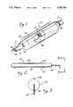
- FIG. 1is a partial perspective view of a cutter assembly in accordance with an embodiment of the present invention
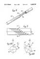
- FIG. 2is a side elevation view of an alternative embodiment of the cutter assembly in accordance with an alternate embodiment of the present invention
- FIG. 3is a section view taken along the line 3--3 of FIG. 2;
- FIG. 4is a view similar to FIG. 1, showing an alternate embodiment in accordance with the present invention.
- FIG. 6Ais a radial view of the cutter assembly in FIG. 5, showing one step in an alignment procedure of the present invention.
- a fluoroscopically alignable assemblyin the embodiment illustrated a cutter assembly 10, is shown which is in accordance with an embodiment of the present invention.
- the assembly 10includes a longitudinally extending cutting element support 12, having a distal end portion 14 and a proximal end portion 17 and being extendable into a body cavity, orifice or conduit (not shown).
- a balloon or bladder 20is supported by the cutting element support 12 and the cutting element 18 is supported by the balloon 20.
- a currentis allowed to pass from an active cutting electrode through a patient's tissue and into a grounding pad or cable.
- the currentcuts tissue at the active cutting electrode, the cutting rate being dependant on current density through the tissue in that area. At low current density heat is generated but no cut is achieved. At high current density fast cutting occurs.
- the currentpasses from the active cutting electrode through the patient's tissue to a return electrode which is located in, or is in contact with, the patient's tissue a short distance away from the cutting electrode.
- the cutting and return electrodesare generally carried by a single instrument.
- the objective in electrosurgical cuttingis to heat the tissues cells so rapidly that they explode into steam leaving a cavity in the cell matrix.
- the heatis meant to be dissipated in the steam and to not conduct through the tissue to thereby dry out adjacent cells.
- Such electrosurgical cuttinginvolves the sparking of the current to the tissue.
- the current utilizedis in the radio frequency range and operates by the radio frequency current jumping across an air gap to the tissue. This is known as sparking.
- a radiopaque marker pattern 22is provided and is carried by the cutting element support 12.
- the pattern 22is such that by fluoroscopic viewing of the pattern 22 (and usually the cutting element 18, as well), a user can determine the angular orientation of the cutting element 18 about its longitudinal axis 26.
- the pattern 22is in the nature of a radiopaque wire 24 which fits in a passage in the cutting element support 12.
- the cutting element 18is aligned to out directly upwardly (the possibility of a 180° misalignment is avoidable since the cutter assembly 10 can be inserted with sufficient care so that it is less than 90° out of alignment) from the longitudinally extending cutting element support 12.
- the assembly 10can have markers on its proximal(out-of-body) end to allow positioning within 45° of the desired target orientation.
- the cutter assembly 10is otherwise aligned, for example if it is rotated some number of degrees about the illustrated axis 26, then the surgeon will see two lines in the fluoroscopic picture, one corresponding to the cutting element 18 and the other to the wire 24 (one or more of the lines forming the radiopaque pattern 22 can be made distinguishable from the line representative of the cutter element 18, for example, the pattern lines can be dashed lines, have transverse dashes across them, or the like). The surgeon can then rotate the cutter assembly 10 about the axis 26 until the two visible lines coincide to properly position the cutting element 18 directly above the wire 24.
- the radiopaque marker pattern 22is made up of lines which are relatively thin.
- such lineswhether they are made up of wires or are in the nature of radiopaque inks, are no greater in extension (diameter in the case of wires) than is the cutting element 18 itself. If the lines which make up the marker pattern 22 are significantly wider than the cutting element 18 there is an alignment error results since the cutting element 18 can be misaligned at any location opposite the width of the potentially wider lines of the marker pattern 22. Thus, it is preferred that the Width of the lines of the marker pattern 22 be no greater than the width of the cutting element 18.
- FIGS. 2 and 3show an embodiment of the invention wherein the marker pattern 22 comprises two radiopaque markers 28 and 30, each parallel to and extending along the support 12 and each being on the same diameter as seen in FIG. 3.
- the radiopaque markers 28 and 30can be aligned to appear to be only a single line, thus assuring proper orientation of, for example, a cutting loop 32, which extends from the distal end portion 14 of the cutting element support 12.
- FIG. 4illustrates an embodiment of a cutter assembly 10'' very much like that of FIG. 3, but wherein the radiopaque marker pattern 22 is in the nature of two wires 34 and 36, both within appropriate passages in the cutting element support 12.
- a cutting elementis not shown but, if present, would extend from the distal end portion of the cutting element support 12. This embodiment is also useful if the element being aligned is not a cutting element and is not itself radiopaque.
- FIGS. 5 and 6A and 6Billustrate an embodiment of the present invention wherein the cutter assembly 10''' serves for orientating the cutting element 18 at a desired angle relative to the axis 26.
- Each of the radiopaque indicator lines 38is a different distance from this intersection line in order to allow selective angular orientation of the cutting element 18 while it is within a body vessel, cavity, or conduit.
- the cutting element support 12can be rotated until the cutting element 18 appears to be over any one of the opaque indicator lines 38, which can be in the nature of radiopaque lines or can be imbedded wires, whereby a cut may be made at a desired orientation about the axis 26.
- FIGS. 6A and 6Billustrate the alignment procedure.
- radiopaque markers 40 and 42one of which is each end of the cutting element 18.
- the surgeoncan observe not only the radial direction in which the cutting element 18 is going to proceed on inflating of the balloon 20, but also just where along a body conduit the cutting element 18 is going to cut into the particular body conduit.
- the alignable cutter assembly 10, 10', 10'', or 10'''is inserted in a body vessel, cavity, or conduit to the desired depth. Fluoroscopic images are obtained of the cutter assembly 10, 10', 10'', or 10''', within the body.
- the cutting element 18is then aligned in a desired angular orientation relative to the axis 26 using the radiopaque marker pattern 22.
- the precise depth within the bodycan also be adjusted by observing the radiopaque markers 40 and 42, when present.
- incisingis carried out in the desired direction. If desired, the element can be reoriented in a different angular orientation and an additional incision can be made.
- the present inventionprovides a cutter assembly 10 which allows a cutting element 18 to be aligned properly within a body vessel, cavity, or conduit so as to provide an incision in a desired direction.
Landscapes
- Health & Medical Sciences (AREA)
- Life Sciences & Earth Sciences (AREA)
- Surgery (AREA)
- Engineering & Computer Science (AREA)
- Animal Behavior & Ethology (AREA)
- Veterinary Medicine (AREA)
- Biomedical Technology (AREA)
- Heart & Thoracic Surgery (AREA)
- Medical Informatics (AREA)
- Molecular Biology (AREA)
- Nuclear Medicine, Radiotherapy & Molecular Imaging (AREA)
- General Health & Medical Sciences (AREA)
- Public Health (AREA)
- Vascular Medicine (AREA)
- Cardiology (AREA)
- Physics & Mathematics (AREA)
- Plasma & Fusion (AREA)
- Otolaryngology (AREA)
- Oral & Maxillofacial Surgery (AREA)
- Pathology (AREA)
- Media Introduction/Drainage Providing Device (AREA)
Abstract
Description
Claims (32)
Priority Applications (1)
| Application Number | Priority Date | Filing Date | Title |
|---|---|---|---|
| US07/824,897US5209749A (en) | 1990-05-11 | 1992-01-22 | Fluoroscopically alignable cutter assembly and method of using the same |
Applications Claiming Priority (2)
| Application Number | Priority Date | Filing Date | Title |
|---|---|---|---|
| US52224090A | 1990-05-11 | 1990-05-11 | |
| US07/824,897US5209749A (en) | 1990-05-11 | 1992-01-22 | Fluoroscopically alignable cutter assembly and method of using the same |
Related Parent Applications (1)
| Application Number | Title | Priority Date | Filing Date |
|---|---|---|---|
| US52224090AContinuation | 1990-05-11 | 1990-05-11 |
Publications (1)
| Publication Number | Publication Date |
|---|---|
| US5209749Atrue US5209749A (en) | 1993-05-11 |
Family
ID=27060754
Family Applications (1)
| Application Number | Title | Priority Date | Filing Date |
|---|---|---|---|
| US07/824,897Expired - LifetimeUS5209749A (en) | 1990-05-11 | 1992-01-22 | Fluoroscopically alignable cutter assembly and method of using the same |
Country Status (1)
| Country | Link |
|---|---|
| US (1) | US5209749A (en) |
Cited By (78)
| Publication number | Priority date | Publication date | Assignee | Title |
|---|---|---|---|---|
| US5320634A (en)* | 1990-07-03 | 1994-06-14 | Interventional Technologies, Inc. | Balloon catheter with seated cutting edges |
| WO1995024862A1 (en)* | 1994-03-15 | 1995-09-21 | Bauman Robert P | Method for precise atherectomy guidance using ultrasound |
| US5616149A (en)* | 1990-07-03 | 1997-04-01 | Cedars-Sinai Medical Center | Balloon catheter with cutting edge |
| US5713913A (en)* | 1996-11-12 | 1998-02-03 | Interventional Technologies Inc. | Device and method for transecting a coronary artery |
| US5882329A (en)* | 1997-02-12 | 1999-03-16 | Prolifix Medical, Inc. | Apparatus and method for removing stenotic material from stents |
| EP0835075A4 (en)* | 1995-06-30 | 1999-06-23 | Boston Scient Corp | Ultrasound imaging catheter with a cutting element |
| WO1999044523A1 (en)* | 1998-03-05 | 1999-09-10 | Scimed Life Systems, Inc. | Pmr device and method |
| US6090118A (en)* | 1998-07-23 | 2000-07-18 | Mcguckin, Jr.; James F. | Rotational thrombectomy apparatus and method with standing wave |
| US6136014A (en)* | 1998-09-01 | 2000-10-24 | Vivant Medical, Inc. | Percutaneous tissue removal device |
| US6245040B1 (en)* | 1994-01-14 | 2001-06-12 | Cordis Corporation | Perfusion balloon brace and method of use |
| US6319242B1 (en) | 1997-02-12 | 2001-11-20 | Prolifix Medical, Inc. | Apparatus and method for controlled removal of stenotic material from stents |
| EP1166721A2 (en)* | 1995-10-13 | 2002-01-02 | Transvascular, Inc. | Apparatus for transvascular procedures |
| US6471709B1 (en) | 1998-10-30 | 2002-10-29 | Vivant Medical, Inc. | Expandable ring percutaneous tissue removal device |
| US20020173812A1 (en)* | 1997-07-24 | 2002-11-21 | Mcguckin James F. | Rotational thrombectomy device |
| US20030020662A1 (en)* | 2001-04-27 | 2003-01-30 | Brian St. Hillaire | Diversity slot antenna |
| US20030060842A1 (en)* | 2001-09-27 | 2003-03-27 | Yem Chin | Method and apparatus for measuring and controlling blade depth of a tissue cutting apparatus in an endoscopic catheter |
| US20030078606A1 (en)* | 2001-04-17 | 2003-04-24 | Scimed Life Systems, Inc. | In-stent ablative tool |
| EP1356787A1 (en)* | 2002-04-26 | 2003-10-29 | Medtronic Ave, Inc. | Catheter for repair of endoluminal grafts |
| US20040158143A1 (en)* | 1995-10-13 | 2004-08-12 | Transvascular Inc. | Stabilized tissue penetrating catheters |
| US20040176759A1 (en)* | 2003-03-07 | 2004-09-09 | Subashini Krishnamurthy | Radiopaque electrical needle |
| US20040230178A1 (en)* | 2003-05-12 | 2004-11-18 | Show-Mean Wu | Cutting balloon catheter with improved pushability |
| US20050033225A1 (en)* | 2003-08-08 | 2005-02-10 | Scimed Life Systems, Inc. | Catheter shaft for regulation of inflation and deflation |
| US20050038383A1 (en)* | 2003-08-14 | 2005-02-17 | Scimed Life Systems, Inc. | Catheter having a cutting balloon including multiple cavities or multiple channels |
| US20050215950A1 (en)* | 2004-03-26 | 2005-09-29 | Scimed Life Systems, Inc. | Balloon catheter with radiopaque portion |
| US20060106413A1 (en)* | 2004-11-12 | 2006-05-18 | Scimed Life Systems, Inc. | Cutting balloon catheter having flexible atherotomes |
| US20060106412A1 (en)* | 2004-11-12 | 2006-05-18 | Scimed Life Systems, Inc. | Cutting balloon catheter having a segmented blade |
| US20060149308A1 (en)* | 2004-12-30 | 2006-07-06 | Cook Incorporated | Catheter assembly with plaque cutting balloon |
| US20060173487A1 (en)* | 2005-01-05 | 2006-08-03 | Cook Incorporated | Angioplasty cutting device and method for treating a stenotic lesion in a body vessel |
| US20060178685A1 (en)* | 2004-12-30 | 2006-08-10 | Cook Incorporated | Balloon expandable plaque cutting device |
| US20060217705A1 (en)* | 2005-02-17 | 2006-09-28 | Baylis Medical Company Inc. | Electrosurgical device with discontinuous flow density |
| US20060247674A1 (en)* | 2005-04-29 | 2006-11-02 | Roman Ricardo D | String cutting balloon |
| US20060259026A1 (en)* | 2005-05-05 | 2006-11-16 | Baylis Medical Company Inc. | Electrosurgical treatment method and device |
| US20070027449A1 (en)* | 2002-03-05 | 2007-02-01 | Baylis Medical Company Inc. | Electrosurgical device and methods |
| US20070073329A1 (en)* | 2005-09-27 | 2007-03-29 | Cook Incorporated | Balloon catheter with extendable dilation wire |
| US20070106215A1 (en)* | 2005-11-01 | 2007-05-10 | Cook Incorporated | Angioplasty cutting device and method for treating a stenotic lesion in a body vessel |
| US20070149963A1 (en)* | 2004-01-06 | 2007-06-28 | Akinori Matsukuma | Balloon catheter |
| US20070173034A1 (en)* | 2004-03-22 | 2007-07-26 | Semiconductor Energy Laboratory Co., Ltd. | Method for manufacturing integrated circuit |
| US20080147103A1 (en)* | 2005-02-28 | 2008-06-19 | Avraham Shekalim | Apparatus and Method for Removing Deposits from Tubular Structure, Particularly Atheroma from Blood Vessels |
| US20080200944A1 (en)* | 2007-02-13 | 2008-08-21 | Cook Incorporated | Balloon catheter with dilating elements |
| US20080228139A1 (en)* | 2007-02-06 | 2008-09-18 | Cook Incorporated | Angioplasty Balloon With Concealed Wires |
| US20080300610A1 (en)* | 2007-05-31 | 2008-12-04 | Cook Incorporated | Device for treating hardened lesions and method of use thereof |
| US20090024124A1 (en)* | 2005-07-14 | 2009-01-22 | Lefler Amy | Methods for treating the thoracic region of a patient's body |
| US20090054962A1 (en)* | 2002-03-05 | 2009-02-26 | Baylis Medical Company Inc. | Methods for treating the thoracic region of a patient's body |
| US20090125044A1 (en)* | 2007-11-14 | 2009-05-14 | Lary Todd P | Treatment of Coronary Stenosis |
| US20090171283A1 (en)* | 2007-12-27 | 2009-07-02 | Cook Incorporated | Method of bonding a dilation element to a surface of an angioplasty balloon |
| US20090171284A1 (en)* | 2007-12-27 | 2009-07-02 | Cook Incorporated | Dilation system |
| US7566319B2 (en) | 2004-04-21 | 2009-07-28 | Boston Scientific Scimed, Inc. | Traction balloon |
| US7645261B2 (en) | 1999-10-22 | 2010-01-12 | Rex Medical, L.P | Double balloon thrombectomy catheter |
| US20100010521A1 (en)* | 2008-07-10 | 2010-01-14 | Cook Incorporated | Cutting balloon with movable member |
| US7754047B2 (en) | 2004-04-08 | 2010-07-13 | Boston Scientific Scimed, Inc. | Cutting balloon catheter and method for blade mounting |
| US7758604B2 (en) | 2003-05-29 | 2010-07-20 | Boston Scientific Scimed, Inc. | Cutting balloon catheter with improved balloon configuration |
| US20100185082A1 (en)* | 2003-03-07 | 2010-07-22 | Baylis Medical Company Inc. | Device and method for electrosurgery |
| US20110152905A1 (en)* | 2009-12-22 | 2011-06-23 | Cook Incorporated | Balloon with scoring member |
| US7993358B2 (en) | 2005-02-11 | 2011-08-09 | Boston Scientific Scimed, Inc. | Cutting balloon catheter having increased flexibility regions |
| US20110230818A1 (en)* | 2004-06-23 | 2011-09-22 | Boston Scientific Scimed, Inc. | Cutting balloon and process |
| US8192675B2 (en) | 2008-03-13 | 2012-06-05 | Cook Medical Technologies Llc | Cutting balloon with connector and dilation element |
| US20120316589A1 (en)* | 2011-06-07 | 2012-12-13 | Cook Medical Technologies Llc | Balloon catheter with raised elements and visual marker |
| US8414543B2 (en) | 1999-10-22 | 2013-04-09 | Rex Medical, L.P. | Rotational thrombectomy wire with blocking device |
| US20140350396A1 (en)* | 2005-04-27 | 2014-11-27 | C. R. Bard, Inc. | Assemblies for Identifying a Power Injectable Access Port |
| US20150157391A1 (en)* | 2012-04-22 | 2015-06-11 | Newuro, B.V. | Bladder tissue modification for overactive bladder disorders |
| US9216053B2 (en) | 2002-03-05 | 2015-12-22 | Avent, Inc. | Elongate member providing a variation in radiopacity |
| US9233015B2 (en) | 2012-06-15 | 2016-01-12 | Trivascular, Inc. | Endovascular delivery system with an improved radiopaque marker scheme |
| US9949789B2 (en) | 2002-03-05 | 2018-04-24 | Avent, Inc. | Methods of treating the sacroiliac region of a patient's body |
| US9956384B2 (en) | 2014-01-24 | 2018-05-01 | Cook Medical Technologies Llc | Articulating balloon catheter and method for using the same |
| US10080571B2 (en) | 2015-03-06 | 2018-09-25 | Warsaw Orthopedic, Inc. | Surgical instrument and method |
| US10286190B2 (en) | 2013-12-11 | 2019-05-14 | Cook Medical Technologies Llc | Balloon catheter with dynamic vessel engaging member |
| US10441295B2 (en) | 2013-10-15 | 2019-10-15 | Stryker Corporation | Device for creating a void space in a living tissue, the device including a handle with a control knob that can be set regardless of the orientation of the handle |
| US10610294B2 (en) | 2012-04-22 | 2020-04-07 | Newuro, B.V. | Devices and methods for transurethral bladder partitioning |
| WO2020223463A1 (en)* | 2019-05-01 | 2020-11-05 | Saphena Medical, Inc. | Unitary endoscopic vessel harvesting devices with a visual cue to identify cutting elements orientation |
| JP2021166601A (en)* | 2020-04-10 | 2021-10-21 | 住友ベークライト株式会社 | Guide tube |
| US11154320B2 (en) | 2018-04-09 | 2021-10-26 | Boston Scientific Scimed, Inc. | Cutting balloon basket |
| US11291496B2 (en) | 2002-03-05 | 2022-04-05 | Avent, Inc. | Methods of treating the sacroiliac region of a patient's body |
| US20220226043A1 (en)* | 2015-08-21 | 2022-07-21 | Baylis Medical Company Inc. | Transvascular Electrosurgical Devices and Systems and Methods of using the same |
| US11751896B2 (en) | 2013-03-14 | 2023-09-12 | Saphena Medical, Inc. | Unitary endoscopic vessel harvesting devices |
| US11849986B2 (en) | 2019-04-24 | 2023-12-26 | Stryker Corporation | Systems and methods for off-axis augmentation of a vertebral body |
| US12064134B2 (en) | 2013-03-14 | 2024-08-20 | Saphena Medical, Inc. | Unitary endoscopic vessel harvesting devices |
| US12357285B2 (en) | 2019-04-05 | 2025-07-15 | Saphena Medical, Inc. | Unitary device for vessel harvesting and method of using same |
| US12440266B2 (en)* | 2022-04-08 | 2025-10-14 | Boston Scientific Medical Device Limited | Transvascular electrosurgical devices and systems and methods of using the same |
Citations (9)
| Publication number | Priority date | Publication date | Assignee | Title |
|---|---|---|---|---|
| US3605750A (en)* | 1969-04-07 | 1971-09-20 | David S Sheridan | X-ray tip catheter |
| US3847157A (en)* | 1973-06-18 | 1974-11-12 | J Caillouette | Medico-surgical tube |
| US4273128A (en)* | 1980-01-14 | 1981-06-16 | Lary Banning G | Coronary cutting and dilating instrument |
| US4657024A (en)* | 1980-02-04 | 1987-04-14 | Teleflex Incorporated | Medical-surgical catheter |
| US4671291A (en)* | 1986-03-31 | 1987-06-09 | Siemens Medical Systems, Inc. | Angle encoding catheter |
| US4685458A (en)* | 1984-03-01 | 1987-08-11 | Vaser, Inc. | Angioplasty catheter and method for use thereof |
| US4793359A (en)* | 1987-04-24 | 1988-12-27 | Gv Medical, Inc. | Centering balloon structure for transluminal angioplasty catheter |
| US4796637A (en)* | 1987-06-17 | 1989-01-10 | Victory Engineering Company | Radiopaque marker for stereotaxic catheter |
| US4807626A (en)* | 1985-02-14 | 1989-02-28 | Mcgirr Douglas B | Stone extractor and method |
- 1992
- 1992-01-22USUS07/824,897patent/US5209749A/ennot_activeExpired - Lifetime
Patent Citations (9)
| Publication number | Priority date | Publication date | Assignee | Title |
|---|---|---|---|---|
| US3605750A (en)* | 1969-04-07 | 1971-09-20 | David S Sheridan | X-ray tip catheter |
| US3847157A (en)* | 1973-06-18 | 1974-11-12 | J Caillouette | Medico-surgical tube |
| US4273128A (en)* | 1980-01-14 | 1981-06-16 | Lary Banning G | Coronary cutting and dilating instrument |
| US4657024A (en)* | 1980-02-04 | 1987-04-14 | Teleflex Incorporated | Medical-surgical catheter |
| US4685458A (en)* | 1984-03-01 | 1987-08-11 | Vaser, Inc. | Angioplasty catheter and method for use thereof |
| US4807626A (en)* | 1985-02-14 | 1989-02-28 | Mcgirr Douglas B | Stone extractor and method |
| US4671291A (en)* | 1986-03-31 | 1987-06-09 | Siemens Medical Systems, Inc. | Angle encoding catheter |
| US4793359A (en)* | 1987-04-24 | 1988-12-27 | Gv Medical, Inc. | Centering balloon structure for transluminal angioplasty catheter |
| US4796637A (en)* | 1987-06-17 | 1989-01-10 | Victory Engineering Company | Radiopaque marker for stereotaxic catheter |
Cited By (143)
| Publication number | Priority date | Publication date | Assignee | Title |
|---|---|---|---|---|
| US5616149A (en)* | 1990-07-03 | 1997-04-01 | Cedars-Sinai Medical Center | Balloon catheter with cutting edge |
| US5320634A (en)* | 1990-07-03 | 1994-06-14 | Interventional Technologies, Inc. | Balloon catheter with seated cutting edges |
| US6245040B1 (en)* | 1994-01-14 | 2001-06-12 | Cordis Corporation | Perfusion balloon brace and method of use |
| WO1995024862A1 (en)* | 1994-03-15 | 1995-09-21 | Bauman Robert P | Method for precise atherectomy guidance using ultrasound |
| US5485840A (en)* | 1994-03-15 | 1996-01-23 | Bauman; Robert P. | Method of precise guidance for directional atherectomy using ultrasound |
| EP0835075A4 (en)* | 1995-06-30 | 1999-06-23 | Boston Scient Corp | Ultrasound imaging catheter with a cutting element |
| EP1166721A2 (en)* | 1995-10-13 | 2002-01-02 | Transvascular, Inc. | Apparatus for transvascular procedures |
| US7729738B2 (en)* | 1995-10-13 | 2010-06-01 | Medtronic Vascular, Inc. | Stabilized tissue penetrating catheters |
| US20040158143A1 (en)* | 1995-10-13 | 2004-08-12 | Transvascular Inc. | Stabilized tissue penetrating catheters |
| US5713913A (en)* | 1996-11-12 | 1998-02-03 | Interventional Technologies Inc. | Device and method for transecting a coronary artery |
| US5941869A (en)* | 1997-02-12 | 1999-08-24 | Prolifix Medical, Inc. | Apparatus and method for controlled removal of stenotic material from stents |
| US5902263A (en)* | 1997-02-12 | 1999-05-11 | Prolifix Medical, Inc. | Apparatus and method for removing stenotic material from stents |
| US5882329A (en)* | 1997-02-12 | 1999-03-16 | Prolifix Medical, Inc. | Apparatus and method for removing stenotic material from stents |
| US6319242B1 (en) | 1997-02-12 | 2001-11-20 | Prolifix Medical, Inc. | Apparatus and method for controlled removal of stenotic material from stents |
| US6602264B1 (en) | 1997-07-24 | 2003-08-05 | Rex Medical, L.P. | Rotational thrombectomy apparatus and method with standing wave |
| US7037316B2 (en) | 1997-07-24 | 2006-05-02 | Mcguckin Jr James F | Rotational thrombectomy device |
| US7507246B2 (en) | 1997-07-24 | 2009-03-24 | Rex Medical, L.P. | Rotational thrombectomy device |
| US20020173812A1 (en)* | 1997-07-24 | 2002-11-21 | Mcguckin James F. | Rotational thrombectomy device |
| US20020143289A1 (en)* | 1997-11-04 | 2002-10-03 | Scimed Life Systems, Inc. | PMR device and method |
| US6416490B1 (en) | 1997-11-04 | 2002-07-09 | Scimed Life Systems, Inc. | PMR device and method |
| WO1999044523A1 (en)* | 1998-03-05 | 1999-09-10 | Scimed Life Systems, Inc. | Pmr device and method |
| US6090118A (en)* | 1998-07-23 | 2000-07-18 | Mcguckin, Jr.; James F. | Rotational thrombectomy apparatus and method with standing wave |
| US6136014A (en)* | 1998-09-01 | 2000-10-24 | Vivant Medical, Inc. | Percutaneous tissue removal device |
| US6471709B1 (en) | 1998-10-30 | 2002-10-29 | Vivant Medical, Inc. | Expandable ring percutaneous tissue removal device |
| US7645261B2 (en) | 1999-10-22 | 2010-01-12 | Rex Medical, L.P | Double balloon thrombectomy catheter |
| US7909801B2 (en) | 1999-10-22 | 2011-03-22 | Rex Medical, L.P. | Double balloon thrombectomy catheter |
| US8414543B2 (en) | 1999-10-22 | 2013-04-09 | Rex Medical, L.P. | Rotational thrombectomy wire with blocking device |
| US8435218B2 (en) | 1999-10-22 | 2013-05-07 | Rex Medical, L.P. | Double balloon thrombectomy catheter |
| US9017294B2 (en) | 1999-10-22 | 2015-04-28 | Rex Medical, L.P. | Rotational thrombectomy wire with blocking device |
| US6808531B2 (en)* | 2001-04-17 | 2004-10-26 | Scimed Life Systems, Inc. | In-stent ablative tool |
| USRE46581E1 (en)* | 2001-04-17 | 2017-10-24 | Boston Scientific Scimed, Inc. | Cutting balloon catheter |
| US20030078606A1 (en)* | 2001-04-17 | 2003-04-24 | Scimed Life Systems, Inc. | In-stent ablative tool |
| US20030020662A1 (en)* | 2001-04-27 | 2003-01-30 | Brian St. Hillaire | Diversity slot antenna |
| US20030060842A1 (en)* | 2001-09-27 | 2003-03-27 | Yem Chin | Method and apparatus for measuring and controlling blade depth of a tissue cutting apparatus in an endoscopic catheter |
| US20090005637A1 (en)* | 2001-09-27 | 2009-01-01 | Scimed Life Systems, Inc. | Method and Apparatus for Measuring and Controlling Blade Depth of a Tissue Cutting Apparatus in an Endoscopic Catheter |
| US9364281B2 (en) | 2002-03-05 | 2016-06-14 | Avent, Inc. | Methods for treating the thoracic region of a patient's body |
| US20070027449A1 (en)* | 2002-03-05 | 2007-02-01 | Baylis Medical Company Inc. | Electrosurgical device and methods |
| US9216053B2 (en) | 2002-03-05 | 2015-12-22 | Avent, Inc. | Elongate member providing a variation in radiopacity |
| US20090054962A1 (en)* | 2002-03-05 | 2009-02-26 | Baylis Medical Company Inc. | Methods for treating the thoracic region of a patient's body |
| US9949789B2 (en) | 2002-03-05 | 2018-04-24 | Avent, Inc. | Methods of treating the sacroiliac region of a patient's body |
| US10206739B2 (en) | 2002-03-05 | 2019-02-19 | Avent, Inc. | Electrosurgical device and methods |
| US9820808B2 (en) | 2002-03-05 | 2017-11-21 | Avent, Inc. | Method for treating the thoracic region of a patient's body |
| US11291496B2 (en) | 2002-03-05 | 2022-04-05 | Avent, Inc. | Methods of treating the sacroiliac region of a patient's body |
| US20030204236A1 (en)* | 2002-04-26 | 2003-10-30 | Michel Letort | Ballon-tipped, multi-lumen catheter for endoluminal repair of endoluminal leaks in aortic or aorto-iliac endoluminal grafts |
| EP1356787A1 (en)* | 2002-04-26 | 2003-10-29 | Medtronic Ave, Inc. | Catheter for repair of endoluminal grafts |
| US7105031B2 (en) | 2002-04-26 | 2006-09-12 | Medtronic Vascular, Inc. | Balloon-tipped, multi-lumen catheter for endoluminal repair of endoluminal leaks in aortic or aorto-iliac endoluminal grafts |
| US20050159797A1 (en)* | 2003-03-07 | 2005-07-21 | Baylis Medical Company Inc. | Electrosurgical device with improved visibility |
| US7593778B2 (en) | 2003-03-07 | 2009-09-22 | Baylis Medical Company Inc. | Electrosurgical device with improved visibility |
| US20100185082A1 (en)* | 2003-03-07 | 2010-07-22 | Baylis Medical Company Inc. | Device and method for electrosurgery |
| US20040176759A1 (en)* | 2003-03-07 | 2004-09-09 | Subashini Krishnamurthy | Radiopaque electrical needle |
| US8617193B2 (en) | 2003-05-12 | 2013-12-31 | Boston Scientific Scimed, Inc. | Balloon catheter with improved pushability |
| US7632288B2 (en) | 2003-05-12 | 2009-12-15 | Boston Scientific Scimed, Inc. | Cutting balloon catheter with improved pushability |
| US8172864B2 (en) | 2003-05-12 | 2012-05-08 | Boston Scientific Scimed, Inc. | Balloon catheter with improved pushability |
| US20040230178A1 (en)* | 2003-05-12 | 2004-11-18 | Show-Mean Wu | Cutting balloon catheter with improved pushability |
| US7758604B2 (en) | 2003-05-29 | 2010-07-20 | Boston Scientific Scimed, Inc. | Cutting balloon catheter with improved balloon configuration |
| US20050033225A1 (en)* | 2003-08-08 | 2005-02-10 | Scimed Life Systems, Inc. | Catheter shaft for regulation of inflation and deflation |
| US7780626B2 (en) | 2003-08-08 | 2010-08-24 | Boston Scientific Scimed, Inc. | Catheter shaft for regulation of inflation and deflation |
| US20050038383A1 (en)* | 2003-08-14 | 2005-02-17 | Scimed Life Systems, Inc. | Catheter having a cutting balloon including multiple cavities or multiple channels |
| US7887557B2 (en) | 2003-08-14 | 2011-02-15 | Boston Scientific Scimed, Inc. | Catheter having a cutting balloon including multiple cavities or multiple channels |
| US20070149963A1 (en)* | 2004-01-06 | 2007-06-28 | Akinori Matsukuma | Balloon catheter |
| US20070173034A1 (en)* | 2004-03-22 | 2007-07-26 | Semiconductor Energy Laboratory Co., Ltd. | Method for manufacturing integrated circuit |
| US20050215950A1 (en)* | 2004-03-26 | 2005-09-29 | Scimed Life Systems, Inc. | Balloon catheter with radiopaque portion |
| US7754047B2 (en) | 2004-04-08 | 2010-07-13 | Boston Scientific Scimed, Inc. | Cutting balloon catheter and method for blade mounting |
| US8945047B2 (en) | 2004-04-21 | 2015-02-03 | Boston Scientific Scimed, Inc. | Traction balloon |
| US7566319B2 (en) | 2004-04-21 | 2009-07-28 | Boston Scientific Scimed, Inc. | Traction balloon |
| US8986248B2 (en) | 2004-06-23 | 2015-03-24 | Boston Scientific Scimed, Inc. | Cutting balloon and process |
| US20110230818A1 (en)* | 2004-06-23 | 2011-09-22 | Boston Scientific Scimed, Inc. | Cutting balloon and process |
| US20060106413A1 (en)* | 2004-11-12 | 2006-05-18 | Scimed Life Systems, Inc. | Cutting balloon catheter having flexible atherotomes |
| US9603619B2 (en) | 2004-11-12 | 2017-03-28 | Boston Scientific Scimed, Inc. | Cutting balloon catheter having flexible atherotomes |
| US9017353B2 (en) | 2004-11-12 | 2015-04-28 | Boston Scientific Scimed, Inc. | Cutting balloon catheter having flexible atherotomes |
| US8690903B2 (en) | 2004-11-12 | 2014-04-08 | Boston Scientific Scimed, Inc. | Cutting balloon catheter having flexible atherotomes |
| US7291158B2 (en) | 2004-11-12 | 2007-11-06 | Boston Scientific Scimed, Inc. | Cutting balloon catheter having a segmented blade |
| US8361096B2 (en) | 2004-11-12 | 2013-01-29 | Boston Scientific Scimed, Inc. | Cutting balloon catheter having flexible atherotomes |
| US20060106412A1 (en)* | 2004-11-12 | 2006-05-18 | Scimed Life Systems, Inc. | Cutting balloon catheter having a segmented blade |
| US8038691B2 (en) | 2004-11-12 | 2011-10-18 | Boston Scientific Scimed, Inc. | Cutting balloon catheter having flexible atherotomes |
| US20060178685A1 (en)* | 2004-12-30 | 2006-08-10 | Cook Incorporated | Balloon expandable plaque cutting device |
| US7303572B2 (en) | 2004-12-30 | 2007-12-04 | Cook Incorporated | Catheter assembly with plaque cutting balloon |
| US20060149308A1 (en)* | 2004-12-30 | 2006-07-06 | Cook Incorporated | Catheter assembly with plaque cutting balloon |
| US20060173487A1 (en)* | 2005-01-05 | 2006-08-03 | Cook Incorporated | Angioplasty cutting device and method for treating a stenotic lesion in a body vessel |
| US7993358B2 (en) | 2005-02-11 | 2011-08-09 | Boston Scientific Scimed, Inc. | Cutting balloon catheter having increased flexibility regions |
| US20060217705A1 (en)* | 2005-02-17 | 2006-09-28 | Baylis Medical Company Inc. | Electrosurgical device with discontinuous flow density |
| US8951249B2 (en) | 2005-02-17 | 2015-02-10 | Avent Inc. | Electrosurgical device with discontinuous flow density |
| US8465509B2 (en) | 2005-02-28 | 2013-06-18 | Avraham Shekalim | Apparatus and method for removing deposits from tubular structure, particularly atheroma from blood vessels |
| WO2006090366A3 (en)* | 2005-02-28 | 2009-01-08 | Avraham Shekalim | Apparatus and method for removing deposits from tubular structure, particularly atheroma from blood vessels |
| US20080147103A1 (en)* | 2005-02-28 | 2008-06-19 | Avraham Shekalim | Apparatus and Method for Removing Deposits from Tubular Structure, Particularly Atheroma from Blood Vessels |
| US9937337B2 (en)* | 2005-04-27 | 2018-04-10 | C. R. Bard, Inc. | Assemblies for identifying a power injectable access port |
| US20140350396A1 (en)* | 2005-04-27 | 2014-11-27 | C. R. Bard, Inc. | Assemblies for Identifying a Power Injectable Access Port |
| US20060247674A1 (en)* | 2005-04-29 | 2006-11-02 | Roman Ricardo D | String cutting balloon |
| US20060259026A1 (en)* | 2005-05-05 | 2006-11-16 | Baylis Medical Company Inc. | Electrosurgical treatment method and device |
| US20090024124A1 (en)* | 2005-07-14 | 2009-01-22 | Lefler Amy | Methods for treating the thoracic region of a patient's body |
| US20070073329A1 (en)* | 2005-09-27 | 2007-03-29 | Cook Incorporated | Balloon catheter with extendable dilation wire |
| US7708753B2 (en)* | 2005-09-27 | 2010-05-04 | Cook Incorporated | Balloon catheter with extendable dilation wire |
| US20070106215A1 (en)* | 2005-11-01 | 2007-05-10 | Cook Incorporated | Angioplasty cutting device and method for treating a stenotic lesion in a body vessel |
| US8123770B2 (en) | 2005-11-01 | 2012-02-28 | Cook Medical Technologies Llc | Angioplasty cutting device and method for treating a stenotic lesion in a body vessel |
| US9211394B2 (en) | 2007-02-06 | 2015-12-15 | Cook Medical Technologies Llc | Angioplasty balloon with conceal wires |
| US20080228139A1 (en)* | 2007-02-06 | 2008-09-18 | Cook Incorporated | Angioplasty Balloon With Concealed Wires |
| US20080200944A1 (en)* | 2007-02-13 | 2008-08-21 | Cook Incorporated | Balloon catheter with dilating elements |
| US9192747B2 (en) | 2007-02-13 | 2015-11-24 | Cook Medical Technologies Llc | Balloon catheter with dilating elements |
| US8323307B2 (en) | 2007-02-13 | 2012-12-04 | Cook Medical Technologies Llc | Balloon catheter with dilating elements |
| US9119944B2 (en) | 2007-05-31 | 2015-09-01 | Cook Medical Technologies Llc | Device for treating hardened lesions and method of use thereof |
| US20080300610A1 (en)* | 2007-05-31 | 2008-12-04 | Cook Incorporated | Device for treating hardened lesions and method of use thereof |
| US8906049B2 (en) | 2007-05-31 | 2014-12-09 | Cook Medical Technologies Llc | Device for treating hardened lesions and method of use thereof |
| US8870816B2 (en) | 2007-05-31 | 2014-10-28 | Cook Medical Technologies Llc | Device for treating hardened lesions |
| US20090125044A1 (en)* | 2007-11-14 | 2009-05-14 | Lary Todd P | Treatment of Coronary Stenosis |
| US20090171284A1 (en)* | 2007-12-27 | 2009-07-02 | Cook Incorporated | Dilation system |
| US20090171283A1 (en)* | 2007-12-27 | 2009-07-02 | Cook Incorporated | Method of bonding a dilation element to a surface of an angioplasty balloon |
| US10617443B2 (en) | 2008-03-13 | 2020-04-14 | Cook Medical Technologies Llc | Cutting balloon with connector and dilation element |
| US10016212B2 (en) | 2008-03-13 | 2018-07-10 | Cook Medical Technologies Llc | Cutting balloon with connector and dilation element |
| US9604036B2 (en) | 2008-03-13 | 2017-03-28 | Cook Medical Technologies Llc | Cutting balloon with connector and dilation element |
| US8192675B2 (en) | 2008-03-13 | 2012-06-05 | Cook Medical Technologies Llc | Cutting balloon with connector and dilation element |
| US20100010521A1 (en)* | 2008-07-10 | 2010-01-14 | Cook Incorporated | Cutting balloon with movable member |
| US20110152905A1 (en)* | 2009-12-22 | 2011-06-23 | Cook Incorporated | Balloon with scoring member |
| US8348987B2 (en) | 2009-12-22 | 2013-01-08 | Cook Medical Technologies Llc | Balloon with scoring member |
| US9924957B2 (en) | 2010-08-23 | 2018-03-27 | Argon Medical Devices, Inc. | Rotational thrombectomy wire with blocking device |
| US20120316589A1 (en)* | 2011-06-07 | 2012-12-13 | Cook Medical Technologies Llc | Balloon catheter with raised elements and visual marker |
| US10610294B2 (en) | 2012-04-22 | 2020-04-07 | Newuro, B.V. | Devices and methods for transurethral bladder partitioning |
| US20150157391A1 (en)* | 2012-04-22 | 2015-06-11 | Newuro, B.V. | Bladder tissue modification for overactive bladder disorders |
| US9883906B2 (en) | 2012-04-22 | 2018-02-06 | Newuro, B.V. | Bladder tissue modification for overactive bladder disorders |
| US9179963B2 (en)* | 2012-04-22 | 2015-11-10 | Newuro, B.V. | Bladder tissue modification for overactive bladder disorders |
| US10034787B2 (en) | 2012-06-15 | 2018-07-31 | Trivascular, Inc. | Endovascular delivery system with an improved radiopaque marker scheme |
| US9233015B2 (en) | 2012-06-15 | 2016-01-12 | Trivascular, Inc. | Endovascular delivery system with an improved radiopaque marker scheme |
| US11013626B2 (en) | 2012-06-15 | 2021-05-25 | Trivascular, Inc. | Endovascular delivery system with an improved radiopaque marker scheme |
| US11751896B2 (en) | 2013-03-14 | 2023-09-12 | Saphena Medical, Inc. | Unitary endoscopic vessel harvesting devices |
| US12064134B2 (en) | 2013-03-14 | 2024-08-20 | Saphena Medical, Inc. | Unitary endoscopic vessel harvesting devices |
| US11259818B2 (en) | 2013-10-15 | 2022-03-01 | Stryker Corporation | Methods for creating a void within a bone |
| US10441295B2 (en) | 2013-10-15 | 2019-10-15 | Stryker Corporation | Device for creating a void space in a living tissue, the device including a handle with a control knob that can be set regardless of the orientation of the handle |
| US12396738B2 (en) | 2013-10-15 | 2025-08-26 | Stryker Corporation | Device including steering cables for creating a cavity or a channel in bone |
| US10286190B2 (en) | 2013-12-11 | 2019-05-14 | Cook Medical Technologies Llc | Balloon catheter with dynamic vessel engaging member |
| US9956384B2 (en) | 2014-01-24 | 2018-05-01 | Cook Medical Technologies Llc | Articulating balloon catheter and method for using the same |
| US11653934B2 (en) | 2015-03-06 | 2023-05-23 | Warsaw Orthopedic, Inc. | Surgical instrument and method |
| US12433611B2 (en) | 2015-03-06 | 2025-10-07 | Warsaw Orthopedic, Inc. | Surgical instrument and method |
| US10667827B2 (en) | 2015-03-06 | 2020-06-02 | Warsaw Orthopedic, Inc. | Surgical instrument and method |
| US10080571B2 (en) | 2015-03-06 | 2018-09-25 | Warsaw Orthopedic, Inc. | Surgical instrument and method |
| US20220226043A1 (en)* | 2015-08-21 | 2022-07-21 | Baylis Medical Company Inc. | Transvascular Electrosurgical Devices and Systems and Methods of using the same |
| US11154320B2 (en) | 2018-04-09 | 2021-10-26 | Boston Scientific Scimed, Inc. | Cutting balloon basket |
| US11801067B2 (en) | 2018-04-09 | 2023-10-31 | Boston Scientific Scimed, Inc. | Cutting balloon basket |
| US12357285B2 (en) | 2019-04-05 | 2025-07-15 | Saphena Medical, Inc. | Unitary device for vessel harvesting and method of using same |
| US11849986B2 (en) | 2019-04-24 | 2023-12-26 | Stryker Corporation | Systems and methods for off-axis augmentation of a vertebral body |
| US12279799B2 (en) | 2019-04-24 | 2025-04-22 | Stryker Corporation | Systems and methods for off-axis treatment of a vertebral body |
| WO2020223463A1 (en)* | 2019-05-01 | 2020-11-05 | Saphena Medical, Inc. | Unitary endoscopic vessel harvesting devices with a visual cue to identify cutting elements orientation |
| JP7415758B2 (en) | 2020-04-10 | 2024-01-17 | 住友ベークライト株式会社 | guide tube |
| JP2021166601A (en)* | 2020-04-10 | 2021-10-21 | 住友ベークライト株式会社 | Guide tube |
| US12440266B2 (en)* | 2022-04-08 | 2025-10-14 | Boston Scientific Medical Device Limited | Transvascular electrosurgical devices and systems and methods of using the same |
Similar Documents
| Publication | Publication Date | Title |
|---|---|---|
| US5209749A (en) | Fluoroscopically alignable cutter assembly and method of using the same | |
| US5080660A (en) | Electrosurgical electrode | |
| US5672153A (en) | Medical probe device and method | |
| US9011433B2 (en) | Bipolar colpotomy device | |
| US5514131A (en) | Method for the ablation treatment of the uvula | |
| US6287304B1 (en) | Interstitial cauterization of tissue volumes with electrosurgically deployed electrodes | |
| EP0611314B1 (en) | Medical probe device | |
| US6837885B2 (en) | Surgical probe for supporting inflatable therapeutic devices in contact with tissue in or around body orifices and within tumors | |
| CA2082621C (en) | Dilatation catheter assembly with cutting element | |
| ES2323371T3 (en) | ECOGENIC NEEDLE FOR TRANSVAGINAL REDUCTION ASSISTED BY ULTRASOUNDS OF UTERINE FIBROIDS. | |
| US20110238057A1 (en) | Dual Bracketed Energy Delivery Probe and Method of Use | |
| US7361174B2 (en) | Angle indexer for medical devices | |
| US7335198B2 (en) | Accurate cutting about and into tissue volumes with electrosurgically deployed electrodes | |
| JP2018171444A (en) | Balloon catheter with large area electrodes | |
| JPH08508664A (en) | BPH excision method and device | |
| US20070016273A1 (en) | Electrothermal intervertebral disc treatment | |
| JP2003504148A (en) | Electrosurgical lesion localization device | |
| WO2012174375A1 (en) | Radiofrequency ablation catheter device | |
| Kanpolat et al. | Computerized tomography-guided percutaneous extralemniscal myelotomy |
Legal Events
| Date | Code | Title | Description |
|---|---|---|---|
| STCF | Information on status: patent grant | Free format text:PATENTED CASE | |
| CC | Certificate of correction | ||
| FEPP | Fee payment procedure | Free format text:PAT HOLDER CLAIMS SMALL ENTITY STATUS - SMALL BUSINESS (ORIGINAL EVENT CODE: SM02); ENTITY STATUS OF PATENT OWNER: LARGE ENTITY | |
| REFU | Refund | Free format text:REFUND OF EXCESS PAYMENTS PROCESSED (ORIGINAL EVENT CODE: R169); ENTITY STATUS OF PATENT OWNER: LARGE ENTITY | |
| FPAY | Fee payment | Year of fee payment:4 | |
| REFU | Refund | Free format text:REFUND OF EXCESS PAYMENTS PROCESSED (ORIGINAL EVENT CODE: R169); ENTITY STATUS OF PATENT OWNER: LARGE ENTITY | |
| FEPP | Fee payment procedure | Free format text:PAYOR NUMBER ASSIGNED (ORIGINAL EVENT CODE: ASPN); ENTITY STATUS OF PATENT OWNER: LARGE ENTITY | |
| FPAY | Fee payment | Year of fee payment:8 | |
| FEPP | Fee payment procedure | Free format text:PAT HOLDER NO LONGER CLAIMS SMALL ENTITY STATUS, ENTITY STATUS SET TO UNDISCOUNTED (ORIGINAL EVENT CODE: STOL); ENTITY STATUS OF PATENT OWNER: LARGE ENTITY | |
| FPAY | Fee payment | Year of fee payment:12 | |
| AS | Assignment | Owner name:APPLIED MEDICAL RESOURCES CORPORATION, CALIFORNIA Free format text:ASSIGNMENT OF ASSIGNORS INTEREST;ASSIGNOR:APPLIED UROLOGY, INC.;REEL/FRAME:016623/0932 Effective date:20050628 |