US5209461A - Elastomeric torsional spring having tangential spokes with varying elastic response - Google Patents
Elastomeric torsional spring having tangential spokes with varying elastic responseDownload PDFInfo
- Publication number
- US5209461A US5209461AUS07/898,242US89824292AUS5209461AUS 5209461 AUS5209461 AUS 5209461AUS 89824292 AUS89824292 AUS 89824292AUS 5209461 AUS5209461 AUS 5209461A
- Authority
- US
- United States
- Prior art keywords
- hub
- elastomeric
- torsional spring
- cylinder
- spokes
- Prior art date
- Legal status (The legal status is an assumption and is not a legal conclusion. Google has not performed a legal analysis and makes no representation as to the accuracy of the status listed.)
- Expired - Lifetime
Links
Images

Classifications
- A—HUMAN NECESSITIES
- A63—SPORTS; GAMES; AMUSEMENTS
- A63B—APPARATUS FOR PHYSICAL TRAINING, GYMNASTICS, SWIMMING, CLIMBING, OR FENCING; BALL GAMES; TRAINING EQUIPMENT
- A63B21/00—Exercising apparatus for developing or strengthening the muscles or joints of the body by working against a counterforce, with or without measuring devices
- A63B21/02—Exercising apparatus for developing or strengthening the muscles or joints of the body by working against a counterforce, with or without measuring devices using resilient force-resisters
- A63B21/045—Exercising apparatus for developing or strengthening the muscles or joints of the body by working against a counterforce, with or without measuring devices using resilient force-resisters having torsion or bending or flexion element
- A63B21/0455—Exercising apparatus for developing or strengthening the muscles or joints of the body by working against a counterforce, with or without measuring devices using resilient force-resisters having torsion or bending or flexion element having torsion element around its longitudinal axis
- F—MECHANICAL ENGINEERING; LIGHTING; HEATING; WEAPONS; BLASTING
- F16—ENGINEERING ELEMENTS AND UNITS; GENERAL MEASURES FOR PRODUCING AND MAINTAINING EFFECTIVE FUNCTIONING OF MACHINES OR INSTALLATIONS; THERMAL INSULATION IN GENERAL
- F16F—SPRINGS; SHOCK-ABSORBERS; MEANS FOR DAMPING VIBRATION
- F16F1/00—Springs
- F16F1/36—Springs made of rubber or other material having high internal friction, e.g. thermoplastic elastomers
- F16F1/42—Springs made of rubber or other material having high internal friction, e.g. thermoplastic elastomers characterised by the mode of stressing
- F16F1/48—Springs made of rubber or other material having high internal friction, e.g. thermoplastic elastomers characterised by the mode of stressing loaded mainly in torsion
- F—MECHANICAL ENGINEERING; LIGHTING; HEATING; WEAPONS; BLASTING
- F16—ENGINEERING ELEMENTS AND UNITS; GENERAL MEASURES FOR PRODUCING AND MAINTAINING EFFECTIVE FUNCTIONING OF MACHINES OR INSTALLATIONS; THERMAL INSULATION IN GENERAL
- F16F—SPRINGS; SHOCK-ABSORBERS; MEANS FOR DAMPING VIBRATION
- F16F2236/00—Mode of stressing of basic spring or damper elements or devices incorporating such elements
- F16F2236/08—Torsion
Definitions
- This inventionrelates generally to a torsional spring for use in exercise equipment and, more particularly, to a torsional spring formed from a plurality of elastomeric spokes connected between an outer cylinder and a rotatable central hub.
- the rubber bandsare stretched and wrapped about the axle.
- the first portions of the rubber bands that are in actual contact with the axlecease to stretch when they come in contact with the axle. These first portions of the rubber bands are, therefore, subject to a relatively small amount of strain.
- the second portions of the rubber bands that are not in contact with the axlecontinue to stretch and are subject to substantially higher amounts of strain.
- the fatigue life of the rubber bandis directly related to the peak strain, the second portions of the rubber bands have a relatively shorter fatigue life than the first portions of the rubber bands.
- the overall fatigue life of the rubber bandsis, of course, determined by the relatively short fatigue life of the second portion.
- the present inventionis directed to overcoming one or more of the problems set forth above.
- a torsional springin one aspect of the present invention, includes a cylinder having an inner and outer circumferential surface, a hub positioned substantially centrally within the cylinder, and a plurality of elastomeric spokes extending radially between the inner circumferential surface of the cylinder and the hub.
- Each of the elastomeric spokesis formed from first and second radial segments wherein the first radial segment has a lower elastic modulus than the second radial segment.
- a torsional springin another aspect of the present invention, includes a cylinder having an inner and outer circumferential surface, a hub positioned substantially centrally within the cylinder, and a plurality of elastomeric spokes extending radially between the inner circumferential surface of the cylinder and the hub along a line substantially tangential to the hub.
- Each of the elastomeric spokesis formed from first and second radial segments wherein the first radial segment is adjacent the hub and has a lower elastic modulus than the second radial segment.
- a torsional springin yet another aspect of the present invention, includes a cylinder having an inner and outer circumferential surface, a hub positioned substantially centrally within the cylinder, and a plurality of elastomeric spokes extending radially between the inner circumferential surface of the cylinder and the hub along a line substantially tangential to the hub.
- a torsional spring for use in an exercise machineincludes a cylinder, a hub centered within the cylinder, and a plurality of elastomeric spokes arcuately distributed between the cylinder and the hub.
- the inner end of each spokeis bonded generally tangential to the hub and the outer end of each spoke is bonded to the cylinder.
- Each of the inner ends of the spokeshas a lower elastic modulus than the elastic modulus of the outer end.
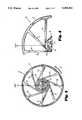
- FIG. 1illustrates a side view of a torsional spring embodying the principles of the instant invention
- FIG. 2illustrates a partial cross sectional end view of a torsional spring embodying the principles of the instant invention
- FIG. 3illustrates a side view of the torsional spring of FIG. 1 in a stressed configuration
- FIG. 4illustrates a side view of an alternative embodiment of a torsional spring embodying the principles of the instant invention.
- FIG. 1a side view of a torsional spring 10 is illustrated.
- the torsional spring 10has been specifically designed for use in exercise equipment of the type described in co-pending U.S. application No. 300,563.
- the torsional spring 10is readily adaptable for use in any other environment where lightweight, long-lived springs are useful.
- the torsional spring 10is not limited to the field of exercise equipment.
- the torsional spring 10includes a cylinder 12 constructed from any suitably stiff material so as to resist substantial deformation thereof.
- the cylinder 12can be constructed from any of a variety of metals, such as mild steel, or may take the form of nylon, plastic, or any suitable composite material.
- the cylinder 12is connected to a central hub 14 through a series of eight elastomeric spokes 16, 18, 20, 22, 24, 26, 28, and 30.
- the central hub 14is constructed from any suitably stiff material so as to resist substantial deformation thereof.
- the central hub 14can be constructed from any of a variety of metals, such as mild steel or may take the form of nylon, plastic, or any suitable composite material.
- the elastomeric spokes 16-30are connected to the inner periphery of the cylinder 12 at regularly spaced circumferential intervals of approximately 45 degrees.
- the number and spacing of the elastomeric spokes 16-30are not critical to operation of the torsional spring 10 but are at least partially determinative of the force required to rotate the cylinder 12 relative to the hub 14.
- the elastomeric spokes 16-30are of substantially identical length so that the central hub 14 is disposed at about the center point of the cylinder 12.
- the elastomeric spokes 16-30are constructed from any suitable elastomeric polymer, but a blend of the two polymers natural rubber and polybutadiene in the ratio of approximately 80% natural rubber to 20% polybutadiene has exhibited an acceptable fatigue life.
- a torsional spring of the type discussed hereinhas been shown to have a useful life in excess of 100,000 cycles of rotating the cylinder 12 relative to the hub 14 through an angle of approximately 200 degrees.
- the elastomeric spokes 16-30are preferably molded in place and bonded to the cylinder 12 and hub 14 by, for example, the use of commercially available coating systems.
- the cylinder 12 and hub 14are placed in and become part of the mold used to form the elastomeric spokes 16-30.
- the elastomeric compoundis preferably injected into the mold so that formation of the torsional spring 10 is substantially completed when the elastomeric compound is injected into the mold. In other words, the bonding and injecting processes occur at substantially the same time.
- the elastomeric spokes 16-30are the most likely component of the torsional spring 10 to exhibit a relatively short fatigue life.
- the fatigue life of the torsional spring 10has been shown to be directly correlated to the peak strain exhibited within each elastomeric spoke 16-30.
- the peak strainis a direct function of the length of each of the elastomeric spokes 16-30.
- exercise equipment employing the torsional spring 10be lightweight and have a small, portable design. Therefore, the physical packaging restraints imposed on the torsional spring 10 limit the designers' ability to increase the length of the elastomeric spokes 16-30 by increasing the diameter of the cylinder 12
- the elastomeric spokes 16-30 of the torsional spring 10 described hereinare provided with their maximum possible length for a given diameter of the cylinder 12 by extending the spokes 16-30 from the inner periphery of the cylinder 12 to the hub 14 along a line substantially tangential to the inner hub 14. In this manner, the length of the elastomeric spoke 16-30 is maximized for a given diameter of the cylinder 12.
- each of the elastomeric spokes 16-30stretches and wraps around the inner hub 14.
- the portion of each of the elastomeric spokes 16-30 that is in contact with the central hub 14 and the underlying elastomeric spokesno longer stretches.
- any additional stretching that occurs within the elastomeric spokes 16-30is confined to the region of the elastomeric spokes 16-30 between the inner periphery of the cylinder 12 and the last point of contact between the hub 14 or underlying elastomeric spokes and each of the elastomeric spokes 16-30.
- the portion of the elastomeric spokes 16-30 that contacts the hub 14 or underlying elastomeric spokesceases to stretch at a relatively low strain while the portion of the elastomeric spokes 16-30 that are not in contact with the hub 14 or underlying spokes continue to stretch and, therefore, attain a much higher strain.
- the phrase "last point of contact"is a relative term and indicates the last point of contact for a preselected rotation.
- the last point of contact identified by reference numeral 34corresponds to the location where the last point of contact occurs for a rotation of 200 degrees. Additional rotation beyond 200 degrees causes the spoke 28 to further wrap around the hub 14 and underlying spokes so that the last point of contact is located radially outward from the last point of contact identified by reference numeral 34.
- the effective length of the elastomeric spoke 28is substantially shorter since subsequent stretching beyond 200 degrees occurs only in the region between reference numeral 34 and the inner periphery of the cylinder 12. Therefore, the peak strain experienced by the elastomeric spoke 28 occurs within this effectively shortened length and is substantially higher than the peak strain experienced by the portion of the elastomeric spoke that contacts the hub 14 or underlying elastomeric spokes.
- the peak strain in the elastomeric spokes 16-30is reduced by decreasing the elastic modulus of each of the elastomeric spoke 16-30 in a first radial segment of each of the elastomeric spokes that is adjacent the hub 14.
- the first radial section of each of the elastomeric spokes 16-30is more elastic than the remaining radial segment of each of the elastomeric spoke 16-30.
- the first radial segment of each of the elastomeric spokes 16-30stretches further to increase the peak strain in the first radial segment. Increased strain in the first radial segment results in a lower peak strain in the second radial segment, thereby reducing the overall peak strain in the elastomeric spokes 16-30.
- the elastic modulus of the elastomeric spokes 16-30vary along the radial length of the elastomeric spoke at least within the portion of the elastomeric spoke that wraps around and comes into contact with the hub 14 and underlying spokes.
- the elastomeric spoke 28have an elastic modulus that varies in the radial segment between the last point of contact 34 and its connection to the hub 14.
- the location of the last point of contact 34is determined by the expected rotation of the cylinder 12 relative to the hub 14. For example, if the expected use for the spring 10 confines its rotational movement to 200 degrees then the location identified by reference numeral 34 reflects the location of the last point of contact.
- the elastic modulusvary at a rate corresponding to its distance from the hub. It should be appreciated that the first segments of the elastomeric spoke 16-30 that are closer to the hub 14 contact the hub 14 earlier in the rotation and thus, cease to stretch at a much lower level of strain. Therefore, it is desireable that the elastomeric spokes 16-30 have a greater elasticity immediately adjacent the hub 14 than at the last point of contact.
- the magnitude of the elastic modulus of each of the elastomeric spokes 16-30is controlled by varying the cross-sectional area of each of the elastomeric spokes 16-30 in proportion to the distance from the hub 14. In other words, increases with increasing distance from the hub 14.
- the cross-sectional area of each of the elastomeric spokes 16-30is accomplished by varying at least one of the axial and circumferential dimensions of each of the elastomeric spokes 16-30. In the preferred embodiment illustrated herein, the circumferential dimension of each of the elastomeric spokes 16-30 increases with increasing distance from the hub 14.
- the elastomeric spokes 16-30are tapered so that they have a narrower circumferential width adjacent the spokes 16-30 are less stiff in the radial segment adjacent the hub than in the radial segment adjacent the cylinder 12.
- the elastomeric spokes 16-30are tapered at an angle of approximately 1.5 degrees.
- the torsional spring 10is readily “stackable” with similarly configured torsional springs 10 so that both of the springs 10 operate in tandem, effectively resisting rotation thereof with twice the force of a single torsional spring 10.
- the hub 14To stack the torsional springs 10, the hub 14 includes a drive mechanism 35 extending from a first axial end portion of said hub 14.
- the hub 14also has a recess 36 extending into its second axial end portion.
- Both the drive mechanism 35 and the recess 36have substantially similar cross-sectional configurations so that the recess 36 readily receives a drive mechanism 35 of a similarly configured torsional spring 10.
- the hubs 14 of the torsional springs 10are mated together and cannot rotate relative to one another.
- increased resistance to rotation of the torsional spring 10is effected by increasing the thickness of each of the elastomeric spokes 16-30 (either in the circumferential or axial direction), or by increasing the total number of elastomeric spokes 16-30.
- exercise equipment employing the torsional spring 10may be readily configured to a desired resistance by selecting torsional springs of various axial sizes or by stacking torsional springs 10 to arrive at a desired combination of resistance, or through a combination of the two methods.
- the elastomeric spokes 16-30are shown connected to the cylinder 12 wherein the circumferential side walls of the elastomeric spokes 16-30 are connected at slightly different angles to the cylinder 12.
- the connection point between the elastomeric spoke 16-30 and the cylinder 12occurs through a radius section of the elastomeric spoke 16-30.
- the counterclockwise side and clockwise side radiuses of the elastomeric spokes 16-30are 1/8 of an inch and 1/4 of an inch, respectively.
- Elastomeric spokes 18-24are each shown having first and second radial segments 38, 40.
- the first radial segment 38is constructed from a compound having a first preselected elastic modulus while the second radial segment 40 is formed from a compound that has a second, higher preselected elastic modulus, the variation in the elastic modulus being achieved by appropriate compounding.
- the first radial segment 38has a lower elastic modulus then the second radial segment 40 and, therefore, like the first radial segment 38 of the embodiment illustrated in FIGS. 1-3, it is less stiff and stretches to a greater length than the second radial segment 40.
- the peak strain experienced by the first radial segment 38is increased while the peak strain experience by the second radial segment 40 is correspondingly decreased so as to decrease the overall peak strain experience by the elastomeric spoke 24.
- the first and second radial segments 38, 40are formed from different compounds during the molding stage of the construction of the torsional spring 10.
- the cylinder 12 and hub 14are located within and form part of the mold for receiving the elastomeric compounds. The compounds are then injected into their corresponding regions to fill the mold and thereby form the elastomeric spokes 16-30.
- the first and second radial segments 38, 40are readily formed.
Landscapes
- Health & Medical Sciences (AREA)
- Engineering & Computer Science (AREA)
- General Engineering & Computer Science (AREA)
- Life Sciences & Earth Sciences (AREA)
- Biophysics (AREA)
- Orthopedic Medicine & Surgery (AREA)
- General Health & Medical Sciences (AREA)
- Physical Education & Sports Medicine (AREA)
- Child & Adolescent Psychology (AREA)
- Mechanical Engineering (AREA)
- Springs (AREA)
Abstract
Description
Claims (15)
Priority Applications (1)
| Application Number | Priority Date | Filing Date | Title |
|---|---|---|---|
| US07/898,242US5209461A (en) | 1990-07-23 | 1992-06-12 | Elastomeric torsional spring having tangential spokes with varying elastic response |
Applications Claiming Priority (2)
| Application Number | Priority Date | Filing Date | Title |
|---|---|---|---|
| US55689390A | 1990-07-23 | 1990-07-23 | |
| US07/898,242US5209461A (en) | 1990-07-23 | 1992-06-12 | Elastomeric torsional spring having tangential spokes with varying elastic response |
Related Parent Applications (1)
| Application Number | Title | Priority Date | Filing Date |
|---|---|---|---|
| US55689390AContinuation | 1990-07-23 | 1990-07-23 |
Publications (1)
| Publication Number | Publication Date |
|---|---|
| US5209461Atrue US5209461A (en) | 1993-05-11 |
Family
ID=27071289
Family Applications (1)
| Application Number | Title | Priority Date | Filing Date |
|---|---|---|---|
| US07/898,242Expired - LifetimeUS5209461A (en) | 1990-07-23 | 1992-06-12 | Elastomeric torsional spring having tangential spokes with varying elastic response |
Country Status (1)
| Country | Link |
|---|---|
| US (1) | US5209461A (en) |
Cited By (43)
| Publication number | Priority date | Publication date | Assignee | Title |
|---|---|---|---|---|
| DE4340903A1 (en)* | 1992-12-05 | 1994-06-09 | Phoenix Ag | Rubber compsns. based on natural rubber and poly:octenamer - have high dynamic loading capability at low dynamic stiffening and high damping |
| US5547174A (en)* | 1992-08-25 | 1996-08-20 | Firma Carl Freudenberg | Bearing |
| US5760506A (en)* | 1995-06-07 | 1998-06-02 | The Boeing Company | Flywheels for energy storage |
| WO2000007673A1 (en) | 1998-08-07 | 2000-02-17 | Leonardo, Inc. | Resistance exercise machine with series connected resistance packs |
| US6146044A (en)* | 1997-09-02 | 2000-11-14 | California Institute Of Technology | Rotary flexure |
| US6182531B1 (en)* | 1998-06-12 | 2001-02-06 | The Boeing Company | Containment ring for flywheel failure |
| US6211589B1 (en) | 1995-06-07 | 2001-04-03 | The Boeing Company | Magnetic systems for energy storage flywheels |
| US6241224B1 (en)* | 1999-09-30 | 2001-06-05 | Xerox Corporation | Torsion spring |
| US6247382B1 (en)* | 1998-08-06 | 2001-06-19 | Fuji Jukogyo Kabushiki Kaisha | Composite material flywheel device |
| US6440044B1 (en)* | 1998-08-07 | 2002-08-27 | Spiraflex, Inc. | Resistance mechanism with series connected resistance packs |
| US20050025615A1 (en)* | 2003-07-30 | 2005-02-03 | The Boeing Company | High energy containment device and turbine with same |
| US20060063650A1 (en)* | 2004-09-17 | 2006-03-23 | Francis Paul S | Resistance exercise machine with stacked resistance packs |
| WO2006042275A2 (en) | 2004-10-12 | 2006-04-20 | Nautilus, Inc. | Exercise device |
| USD521087S1 (en) | 2004-09-17 | 2006-05-16 | Spiraflex, Inc. | Resistance pack for exercise machines |
| US20060105888A1 (en)* | 2004-11-12 | 2006-05-18 | Piane Robert A Jr | Exercise apparatus using weights and springs for high-speed training |
| US7070545B2 (en) | 2002-07-01 | 2006-07-04 | Nautilus, Inc. | Leg press and abdominal crunch exercise machine |
| US7083554B1 (en) | 1997-02-27 | 2006-08-01 | Nautilus, Inc. | Exercise machine with infinite position range limiter and automatic belt tensioning system |
| US7108641B2 (en) | 2000-05-03 | 2006-09-19 | Nautilus, Inc. | Exercise equipment with multi-positioning handles |
| US7115080B2 (en) | 2002-08-01 | 2006-10-03 | Nautilus, Inc. | Collapsible seat for combination hack squat and leg press machine |
| USD533910S1 (en) | 2005-03-15 | 2006-12-19 | Nautilus, Inc. | Exercise device |
| US7189190B2 (en) | 2000-03-10 | 2007-03-13 | Nautilus, Inc. | Group program for resistance exercise training |
| US7195584B1 (en) | 2004-07-20 | 2007-03-27 | Brunswick Corporation | Exercise apparatus for resistance training |
| US20070199727A1 (en)* | 2006-02-27 | 2007-08-30 | Woco Industrietechnik Gmbh | Centrifugal compressor housing |
| US20080205976A1 (en)* | 2007-02-27 | 2008-08-28 | Thales | Webbed through pivot |
| US20080304960A1 (en)* | 2007-06-11 | 2008-12-11 | Woco Industrietechnik Gmbh | Plastic compressor housing and method for producing a plastic compressor housing |
| US20090053051A1 (en)* | 2007-02-27 | 2009-02-26 | Woco Industrietechnik Gmbh | Plastic compressor housing and method for producing same |
| US7507190B2 (en) | 2003-12-15 | 2009-03-24 | Bvp Holding, Inc. | Exercise apparatus |
| US20090078079A1 (en)* | 2007-09-26 | 2009-03-26 | Hillsdale Automotive, Llc | Decoupled vibration damper |
| US20090078078A1 (en)* | 2007-09-26 | 2009-03-26 | Suhale Manzoor | Decoupled vibration damper |
| FR2945982A1 (en)* | 2009-05-27 | 2010-12-03 | Peugeot Citroen Automobiles Sa | Detent stop forming device for suspension element of vehicle i.e. motor vehicle, has return units constituted by frameworks and hubs, where frameworks are connected to hubs by elastically deformable arms |
| US7922635B2 (en) | 2000-03-10 | 2011-04-12 | Nautilus, Inc. | Adjustable-load unitary multi-position bench exercise unit |
| CN102248856A (en)* | 2008-08-28 | 2011-11-23 | 株式会社岛野 | Rear wheel spoke rim for bicycle |
| USD675688S1 (en) | 2012-01-30 | 2013-02-05 | Francis Paul S | Personal exercise device |
| US8597164B2 (en) | 2011-09-10 | 2013-12-03 | Spiraflex, Inc. | Personal exercise device |
| WO2014151825A1 (en) | 2013-03-15 | 2014-09-25 | Oil States Industries, Inc. | Elastomeric load compensators for load compensation of cranes |
| WO2015136488A1 (en) | 2014-03-13 | 2015-09-17 | Oil States Industries, Inc | Load compensator having tension spring assemblies contained in a tubular housing |
| WO2017222802A1 (en)* | 2016-06-23 | 2017-12-28 | Spiraflex Inc. | Exercise device and preloaded resistance pack |
| US10288121B2 (en)* | 2014-11-13 | 2019-05-14 | National Technology & Engineering Solutions Of Sandia, Llc | Rotation flexure with temperature controlled modal frequency |
| US20220056979A1 (en)* | 2020-08-18 | 2022-02-24 | Illinois Tool Works Inc. | Silicone free rotational spring hinge dampener |
| USD951376S1 (en)* | 2020-11-20 | 2022-05-10 | Chongqing Qing Er Technology Co. Ltd. | Abdominal wheel |
| CN116255390A (en)* | 2023-03-30 | 2023-06-13 | 福州大学 | Bistable torsion structure based on composite material thin shell |
| US20230258241A1 (en)* | 2022-02-17 | 2023-08-17 | Illinois Tool Works Inc. | High temperature, high torque, polymeric rotational dampener |
| US20230265908A1 (en)* | 2022-02-21 | 2023-08-24 | Schaeffler Technologies AG & Co. KG | Vibration damper made up of spoke spring absorbers |
Citations (13)
| Publication number | Priority date | Publication date | Assignee | Title |
|---|---|---|---|---|
| DE934800C (en)* | 1951-08-28 | 1956-03-22 | Goetzewerke | Suspension system |
| US2846210A (en)* | 1955-04-06 | 1958-08-05 | Carrier Conveyor Corp | Resilient connectors |
| US2915306A (en)* | 1955-06-24 | 1959-12-01 | Albert F Hickman | Rubber torsion spring |
| US3752475A (en)* | 1971-06-21 | 1973-08-14 | A Ott | Axle-mounted wheel exercising device with spring resistance located centrally within the wheel |
| US4008782A (en)* | 1974-04-01 | 1977-02-22 | Etat Francais Represente Par Le Delegue Ministeriel Pour L'armement | Return device for steering mechanism |
| US4235439A (en)* | 1979-05-21 | 1980-11-25 | Super Stretch Co., Ltd. | Friction type exercising device |
| US4625961A (en)* | 1982-12-30 | 1986-12-02 | Brand Dieter C H | Transportable home energy training device and sprocket |
| US4635755A (en)* | 1985-01-16 | 1987-01-13 | Ametek, Inc. | Backwound pre-stressed spring motor and method |
| US4647041A (en)* | 1985-02-04 | 1987-03-03 | Whiteley Neville C | Exercise apparatus |
| US4647035A (en)* | 1984-07-16 | 1987-03-03 | Robert Yellen | Rowing exercise device |
| US4784006A (en)* | 1985-12-30 | 1988-11-15 | Kethley Lancelot I | Gyroscopic propulsion device |
| US4826145A (en)* | 1987-01-23 | 1989-05-02 | Dunlop Limited A British Company | Resilient torsion bearing |
| US4944511A (en)* | 1989-01-23 | 1990-07-31 | Paul S. Francis | Adjustable resilient reel exerciser |
- 1992
- 1992-06-12USUS07/898,242patent/US5209461A/ennot_activeExpired - Lifetime
Patent Citations (13)
| Publication number | Priority date | Publication date | Assignee | Title |
|---|---|---|---|---|
| DE934800C (en)* | 1951-08-28 | 1956-03-22 | Goetzewerke | Suspension system |
| US2846210A (en)* | 1955-04-06 | 1958-08-05 | Carrier Conveyor Corp | Resilient connectors |
| US2915306A (en)* | 1955-06-24 | 1959-12-01 | Albert F Hickman | Rubber torsion spring |
| US3752475A (en)* | 1971-06-21 | 1973-08-14 | A Ott | Axle-mounted wheel exercising device with spring resistance located centrally within the wheel |
| US4008782A (en)* | 1974-04-01 | 1977-02-22 | Etat Francais Represente Par Le Delegue Ministeriel Pour L'armement | Return device for steering mechanism |
| US4235439A (en)* | 1979-05-21 | 1980-11-25 | Super Stretch Co., Ltd. | Friction type exercising device |
| US4625961A (en)* | 1982-12-30 | 1986-12-02 | Brand Dieter C H | Transportable home energy training device and sprocket |
| US4647035A (en)* | 1984-07-16 | 1987-03-03 | Robert Yellen | Rowing exercise device |
| US4635755A (en)* | 1985-01-16 | 1987-01-13 | Ametek, Inc. | Backwound pre-stressed spring motor and method |
| US4647041A (en)* | 1985-02-04 | 1987-03-03 | Whiteley Neville C | Exercise apparatus |
| US4784006A (en)* | 1985-12-30 | 1988-11-15 | Kethley Lancelot I | Gyroscopic propulsion device |
| US4826145A (en)* | 1987-01-23 | 1989-05-02 | Dunlop Limited A British Company | Resilient torsion bearing |
| US4944511A (en)* | 1989-01-23 | 1990-07-31 | Paul S. Francis | Adjustable resilient reel exerciser |
Cited By (78)
| Publication number | Priority date | Publication date | Assignee | Title |
|---|---|---|---|---|
| US5547174A (en)* | 1992-08-25 | 1996-08-20 | Firma Carl Freudenberg | Bearing |
| DE4340903C2 (en)* | 1992-12-05 | 1999-11-25 | Phoenix Ag | Use of a rubber compound for the production of a tension hook spring |
| DE4340903A1 (en)* | 1992-12-05 | 1994-06-09 | Phoenix Ag | Rubber compsns. based on natural rubber and poly:octenamer - have high dynamic loading capability at low dynamic stiffening and high damping |
| US5760506A (en)* | 1995-06-07 | 1998-06-02 | The Boeing Company | Flywheels for energy storage |
| US6211589B1 (en) | 1995-06-07 | 2001-04-03 | The Boeing Company | Magnetic systems for energy storage flywheels |
| US7083554B1 (en) | 1997-02-27 | 2006-08-01 | Nautilus, Inc. | Exercise machine with infinite position range limiter and automatic belt tensioning system |
| US6146044A (en)* | 1997-09-02 | 2000-11-14 | California Institute Of Technology | Rotary flexure |
| US6182531B1 (en)* | 1998-06-12 | 2001-02-06 | The Boeing Company | Containment ring for flywheel failure |
| US6247382B1 (en)* | 1998-08-06 | 2001-06-19 | Fuji Jukogyo Kabushiki Kaisha | Composite material flywheel device |
| US6440044B1 (en)* | 1998-08-07 | 2002-08-27 | Spiraflex, Inc. | Resistance mechanism with series connected resistance packs |
| EP1930049A1 (en) | 1998-08-07 | 2008-06-11 | Spiraflex, Inc. | Resistance mechanism with series connected resistance packs |
| EP1494763A4 (en)* | 1998-08-07 | 2006-12-27 | Spiraflex Inc | RESISTANCE MECHANISM WITH RESISTANCE PACKAGES SWITCHED IN SERIES |
| WO2000007673A1 (en) | 1998-08-07 | 2000-02-17 | Leonardo, Inc. | Resistance exercise machine with series connected resistance packs |
| US6241224B1 (en)* | 1999-09-30 | 2001-06-05 | Xerox Corporation | Torsion spring |
| US7922635B2 (en) | 2000-03-10 | 2011-04-12 | Nautilus, Inc. | Adjustable-load unitary multi-position bench exercise unit |
| US20070207447A1 (en)* | 2000-03-10 | 2007-09-06 | Nautilus, Inc. | Group program for resistance exercise training |
| US7189190B2 (en) | 2000-03-10 | 2007-03-13 | Nautilus, Inc. | Group program for resistance exercise training |
| US7608028B2 (en) | 2000-05-03 | 2009-10-27 | Nautilus, Inc. | Exercise equipment with multi-positioning handles |
| US7108641B2 (en) | 2000-05-03 | 2006-09-19 | Nautilus, Inc. | Exercise equipment with multi-positioning handles |
| US7608022B2 (en) | 2002-07-01 | 2009-10-27 | Nautilus, Inc. | Leg press and abdominal crunch exercise machine |
| US7070545B2 (en) | 2002-07-01 | 2006-07-04 | Nautilus, Inc. | Leg press and abdominal crunch exercise machine |
| US7115080B2 (en) | 2002-08-01 | 2006-10-03 | Nautilus, Inc. | Collapsible seat for combination hack squat and leg press machine |
| US20050025615A1 (en)* | 2003-07-30 | 2005-02-03 | The Boeing Company | High energy containment device and turbine with same |
| US7008173B2 (en) | 2003-07-30 | 2006-03-07 | The Boeing Company | High energy containment device and turbine with same |
| US7507190B2 (en) | 2003-12-15 | 2009-03-24 | Bvp Holding, Inc. | Exercise apparatus |
| US7195584B1 (en) | 2004-07-20 | 2007-03-27 | Brunswick Corporation | Exercise apparatus for resistance training |
| US7226397B1 (en) | 2004-07-20 | 2007-06-05 | Brunswick Corporation | Rowing exercise machine |
| US7306549B2 (en) | 2004-09-17 | 2007-12-11 | Spiraflex, Inc. | Resistance exercise machine with stacked resistance packs |
| US7229391B2 (en)* | 2004-09-17 | 2007-06-12 | Spira Flex, Inc. | Resistance exercise machine with stacked resistance packs |
| US20060063650A1 (en)* | 2004-09-17 | 2006-03-23 | Francis Paul S | Resistance exercise machine with stacked resistance packs |
| USD521087S1 (en) | 2004-09-17 | 2006-05-16 | Spiraflex, Inc. | Resistance pack for exercise machines |
| CN101031340B (en)* | 2004-09-17 | 2011-05-18 | 斯派拉弗莱克斯公司 | Resistance exercise machine with stacked resistance packs |
| US20110039665A1 (en)* | 2004-10-12 | 2011-02-17 | Nautilus, Inc. | Exercise device |
| US20060100069A1 (en)* | 2004-10-12 | 2006-05-11 | Nautilus, Inc. | Exercise device |
| US8002677B2 (en) | 2004-10-12 | 2011-08-23 | Nautilus, Inc. | Exercise device |
| WO2006042275A2 (en) | 2004-10-12 | 2006-04-20 | Nautilus, Inc. | Exercise device |
| US7815552B2 (en) | 2004-10-12 | 2010-10-19 | Nautilus, Inc. | Exercise device |
| US20060116249A1 (en)* | 2004-10-12 | 2006-06-01 | Nautilus, Inc. | Exercise device |
| US20060105888A1 (en)* | 2004-11-12 | 2006-05-18 | Piane Robert A Jr | Exercise apparatus using weights and springs for high-speed training |
| US7553262B2 (en) | 2004-11-12 | 2009-06-30 | Bvp Holding, Inc. | Exercise apparatus using weights and springs for high-speed training |
| USD566798S1 (en) | 2005-03-15 | 2008-04-15 | Nautilus, Inc. | Exercise device |
| USD550789S1 (en) | 2005-03-15 | 2007-09-11 | Nautilus, Inc. | Exercise device |
| USD533910S1 (en) | 2005-03-15 | 2006-12-19 | Nautilus, Inc. | Exercise device |
| US20070199727A1 (en)* | 2006-02-27 | 2007-08-30 | Woco Industrietechnik Gmbh | Centrifugal compressor housing |
| US7862298B2 (en) | 2006-02-27 | 2011-01-04 | Woco Industrietechnik Gmbh | Centrifugal compressor housing |
| US20090053051A1 (en)* | 2007-02-27 | 2009-02-26 | Woco Industrietechnik Gmbh | Plastic compressor housing and method for producing same |
| FR2913078A1 (en)* | 2007-02-27 | 2008-08-29 | Alcatel Lucent Sas | PIVOT CROSSING WITH BLADES. |
| US8734043B2 (en)* | 2007-02-27 | 2014-05-27 | Thales | Webbed through pivot |
| US8342800B2 (en) | 2007-02-27 | 2013-01-01 | Woco Industrietechnik Gmbh | Plastic compressor housing and method for producing same |
| US20080205976A1 (en)* | 2007-02-27 | 2008-08-28 | Thales | Webbed through pivot |
| EP1964778A1 (en)* | 2007-02-27 | 2008-09-03 | Thales | Pivot with blades |
| US8419359B2 (en) | 2007-06-11 | 2013-04-16 | Woco Industrietechnik Gmbh | Plastic compressor housing and method for producing a plastic compressor housing |
| US20080304960A1 (en)* | 2007-06-11 | 2008-12-11 | Woco Industrietechnik Gmbh | Plastic compressor housing and method for producing a plastic compressor housing |
| US8091450B2 (en) | 2007-09-26 | 2012-01-10 | Metavation, Llc | Decoupled vibration damper |
| US8117943B2 (en) | 2007-09-26 | 2012-02-21 | Metavation, Llc | Decoupled vibration damper |
| US20090078079A1 (en)* | 2007-09-26 | 2009-03-26 | Hillsdale Automotive, Llc | Decoupled vibration damper |
| US20090078078A1 (en)* | 2007-09-26 | 2009-03-26 | Suhale Manzoor | Decoupled vibration damper |
| CN102248856A (en)* | 2008-08-28 | 2011-11-23 | 株式会社岛野 | Rear wheel spoke rim for bicycle |
| FR2945982A1 (en)* | 2009-05-27 | 2010-12-03 | Peugeot Citroen Automobiles Sa | Detent stop forming device for suspension element of vehicle i.e. motor vehicle, has return units constituted by frameworks and hubs, where frameworks are connected to hubs by elastically deformable arms |
| US8597164B2 (en) | 2011-09-10 | 2013-12-03 | Spiraflex, Inc. | Personal exercise device |
| USD675688S1 (en) | 2012-01-30 | 2013-02-05 | Francis Paul S | Personal exercise device |
| US9688516B2 (en) | 2013-03-15 | 2017-06-27 | Oil States Industries, Inc. | Elastomeric load compensators for load compensation of cranes |
| WO2014151825A1 (en) | 2013-03-15 | 2014-09-25 | Oil States Industries, Inc. | Elastomeric load compensators for load compensation of cranes |
| EP2998262A1 (en) | 2013-03-15 | 2016-03-23 | Oil States Industries, Inc. | Elastomeric load compensators for load compensation of cranes |
| WO2015136488A1 (en) | 2014-03-13 | 2015-09-17 | Oil States Industries, Inc | Load compensator having tension spring assemblies contained in a tubular housing |
| EP3550175A1 (en) | 2014-03-13 | 2019-10-09 | Oil States Industries, Inc | Load compensator having tension spring assemblies contained in a tubular housing |
| US9732820B2 (en) | 2014-03-13 | 2017-08-15 | Oil States Industries, Inc. | Load compensator having tension spring assemblies contained in a tubular housing |
| US10288121B2 (en)* | 2014-11-13 | 2019-05-14 | National Technology & Engineering Solutions Of Sandia, Llc | Rotation flexure with temperature controlled modal frequency |
| WO2017222802A1 (en)* | 2016-06-23 | 2017-12-28 | Spiraflex Inc. | Exercise device and preloaded resistance pack |
| US10343006B2 (en) | 2016-06-23 | 2019-07-09 | Spiraflex Inc. | Exercise device and preloaded resistance pack |
| US12110936B2 (en)* | 2020-08-18 | 2024-10-08 | Illinois Tool Works Inc. | Silicone free rotational spring hinge dampener |
| US20220056979A1 (en)* | 2020-08-18 | 2022-02-24 | Illinois Tool Works Inc. | Silicone free rotational spring hinge dampener |
| USD951376S1 (en)* | 2020-11-20 | 2022-05-10 | Chongqing Qing Er Technology Co. Ltd. | Abdominal wheel |
| USD952071S1 (en)* | 2020-11-20 | 2022-05-17 | Chongqing Qing Er Technology Co. Ltd. | Abdominal wheel |
| US20230258241A1 (en)* | 2022-02-17 | 2023-08-17 | Illinois Tool Works Inc. | High temperature, high torque, polymeric rotational dampener |
| US20230265908A1 (en)* | 2022-02-21 | 2023-08-24 | Schaeffler Technologies AG & Co. KG | Vibration damper made up of spoke spring absorbers |
| US12092184B2 (en)* | 2022-02-21 | 2024-09-17 | Schaeffler Technologies AG & Co. KG | Vibration damper made up of spoke spring absorbers |
| CN116255390A (en)* | 2023-03-30 | 2023-06-13 | 福州大学 | Bistable torsion structure based on composite material thin shell |
Similar Documents
| Publication | Publication Date | Title |
|---|---|---|
| US5209461A (en) | Elastomeric torsional spring having tangential spokes with varying elastic response | |
| US2712742A (en) | Elastic joints | |
| EP0511362B1 (en) | Friction hinge assembly | |
| CA2565434C (en) | Solid work machine tire with resilient body | |
| US7316408B2 (en) | Apparatus and resilient member for resisting torsional forces | |
| US5735746A (en) | Torsional vibration damper with deflectable spokes | |
| KR900017810A (en) | Trapezoidal non-pneumatic tires with support and cushioning members | |
| US4869709A (en) | Driving gear for a bicycle | |
| US4300804A (en) | Hub for a two or three wheel vehicle | |
| WO1998043833A1 (en) | Non-pneumatic ductile tyre | |
| FR2570778A1 (en) | COUPLING OF HIGH ELASTICITY TREES | |
| US4646899A (en) | Torsion damper disc | |
| US5427443A (en) | Annular elastic track | |
| JPH04362401A (en) | Tire | |
| US4952197A (en) | Belt tensioner and method of making the same | |
| JPH05509272A (en) | Improvement of uneven torque transmission mechanisms such as bicycle chain wheel sets | |
| US6286907B1 (en) | Skate wheel with internal radial support | |
| JP3397375B2 (en) | Pneumatic radial tire | |
| US4786068A (en) | Unicycle | |
| WO2005115825A1 (en) | Damper apparatus | |
| CA2272108A1 (en) | Durable, smooth ride wheel and solid rubber tire | |
| RU2245256C2 (en) | Vehicle wheel | |
| US20030060290A1 (en) | Elastic coupling with wirework reinforcement | |
| SE447467B (en) | WHEEL | |
| US5103886A (en) | Pneumatic vehicle tire having bead portions that can be turned in and bead cores embedded in the bead portions |
Legal Events
| Date | Code | Title | Description |
|---|---|---|---|
| STCF | Information on status: patent grant | Free format text:PATENTED CASE | |
| AS | Assignment | Owner name:CONTINENTAL EMSCO COMPANY, TEXAS Free format text:MERGER AND CHANGE OF NAME. EFFECTIVE OCTOBER 1, 1993 IN DELAWARE.;ASSIGNOR:LTV ENERGY PRODUCTS COMPANY OR CONTINENTAL EMSCO COMPANY;REEL/FRAME:006987/0867 Effective date:19930930 | |
| REMI | Maintenance fee reminder mailed | ||
| FPAY | Fee payment | Year of fee payment:4 | |
| FEPP | Fee payment procedure | Free format text:PAYOR NUMBER ASSIGNED (ORIGINAL EVENT CODE: ASPN); ENTITY STATUS OF PATENT OWNER: SMALL ENTITY | |
| AS | Assignment | Owner name:LEONARDO, INC., MISSOURI Free format text:ASSIGNMENT OF ASSIGNORS INTEREST;ASSIGNOR:OIL STATES INDUSTRIES, INC.;REEL/FRAME:011058/0521 Effective date:20000718 Owner name:OIL STATES INDUSTRIES, INC., TEXAS Free format text:MERGER;ASSIGNOR:CONTINENTAL EMSCO COMPANY;REEL/FRAME:011058/0524 Effective date:19930930 | |
| FPAY | Fee payment | Year of fee payment:8 | |
| AS | Assignment | Owner name:SPIRAFLEX, INC., MISSOURI Free format text:CHANGE OF NAME;ASSIGNOR:LEONARDO, INC.;REEL/FRAME:011316/0793 Effective date:20000920 | |
| AS | Assignment | Owner name:CREDIT SUISSE FIRST BOSTON, AS U.S. COLLATERAL AGE Free format text:SECURITY AGREEMENT;ASSIGNORS:OIL STATES;A-Z TERMINAL CORPORATION;CAPSTAR DRILLING, INC.;AND OTHERS;REEL/FRAME:011566/0720 Effective date:20010214 | |
| AS | Assignment | Owner name:WELLS FARGO BANK OF TEXAS, TEXAS Free format text:SECURITY AGREEMENT;ASSIGNORS:OIL STATES INDUSTRIES, INC.;A-Z TERMINAL CORPORATION;CAPSTAR DRILLING, L.P.;AND OTHERS;REEL/FRAME:014709/0287 Effective date:20031031 | |
| FPAY | Fee payment | Year of fee payment:12 | |
| AS | Assignment | Owner name:BOWFLEX INC., WASHINGTON Free format text:CHANGE OF NAME;ASSIGNOR:NAUTILUS, INC.;REEL/FRAME:065820/0610 Effective date:20231017 |