US5207711A - Knee joint prosthesis - Google Patents
Knee joint prosthesisDownload PDFInfo
- Publication number
- US5207711A US5207711AUS07/773,408US77340891AUS5207711AUS 5207711 AUS5207711 AUS 5207711AUS 77340891 AUS77340891 AUS 77340891AUS 5207711 AUS5207711 AUS 5207711A
- Authority
- US
- United States
- Prior art keywords
- tibial
- femoral
- fixation surface
- cement
- prosthesis
- Prior art date
- Legal status (The legal status is an assumption and is not a legal conclusion. Google has not performed a legal analysis and makes no representation as to the accuracy of the status listed.)
- Expired - Lifetime
Links
Images

Classifications
- A—HUMAN NECESSITIES
- A61—MEDICAL OR VETERINARY SCIENCE; HYGIENE
- A61F—FILTERS IMPLANTABLE INTO BLOOD VESSELS; PROSTHESES; DEVICES PROVIDING PATENCY TO, OR PREVENTING COLLAPSING OF, TUBULAR STRUCTURES OF THE BODY, e.g. STENTS; ORTHOPAEDIC, NURSING OR CONTRACEPTIVE DEVICES; FOMENTATION; TREATMENT OR PROTECTION OF EYES OR EARS; BANDAGES, DRESSINGS OR ABSORBENT PADS; FIRST-AID KITS
- A61F2/00—Filters implantable into blood vessels; Prostheses, i.e. artificial substitutes or replacements for parts of the body; Appliances for connecting them with the body; Devices providing patency to, or preventing collapsing of, tubular structures of the body, e.g. stents
- A61F2/02—Prostheses implantable into the body
- A61F2/30—Joints
- A61F2/38—Joints for elbows or knees
- A61F2002/3895—Joints for elbows or knees unicompartimental
Definitions
- the inventionrelates broadly to prosthetic implants, and more particularly, to prostheses for human joints, such as the knee, implantable by means of arthroscopic as well as open surgical techniques.
- the natural knee jointincludes the bottom part of the femur, constituted by the two condyles, the lower parts of which bear upon the complementary shaped upper surface plateaus of the tibia through the intermediary of cartilage or meniscus. Connection through the knee is provided by means of ligaments which also provide joint stability and assist in absorbing stresses applied to the knee.
- the femur, cartilage and tibiaare normally subjected to significant compression loading in supporting the weight of the body.
- Movement of the normal kneeis not a true hinged joint about a single center but, rather, is a complex action including rocking, gliding and axial rotation.
- the rocking movementthen changes to a combined sliding and pivoting movement wherein successive points on the femoral condyles slide forward on the tibial plateaus until full flexion is obtained.
- the flexion movementis polycentric, that is, about different centers which are not fixed in one position but lie in a somewhat spiral or polycentric pathway.
- Knee prostheses of the first categorypossess significant disadvantages in that they generally involve the removal of natural ligaments and only permit motion about a single axis as opposed to the controlled rotation and translation characteristic of a natural, healthy knee.
- Knee prostheses of the second typegenerally include femoral components secured to the condylar surfaces of the femur, typically having cylindrical bearing surfaces, and tibial components fixed to the tibial plateaus, the femoral components bearing against the upper surfaces of corresponding tibial components. Examples of prostheses of the latter type are shown in U.S. Pat. No. 4,470,158 to Pappas et al; U.S. Pat. No. 4,211,228 to Cloutier; U.S. Pat. No. 4,207,627 to Cloutier; and U.S. Pat. No. 3,953,899 to Charnley.
- unicompartmental knee replacementIn addition to total knee replacement, unicompartmental knee replacement is known wherein a single compartment of the knee is surgically restored. Typically, the medial or lateral portion of the tibio-femoral joint is replaced without sacrificing normal remaining structure in the knee.
- U.S. Pat. No. 4,340,978 to Buechel et aldiscloses a unicompartmental knee replacement device including a tibial platform secured to the tibia and having a track for receiving a bearing insert.
- a femoral componentis attached to one of the condylar surfaces of the femur and is provided with a generally convex spherical inferior surface for engaging the superior surface of the bearing insert. Similar unicompartmental knee implants are shown in U.S.
- the misalignment and anchoring problems associated with conventional prosthesesare due in part to the fact that the prosthesis is secured in place by means of cement applied to the prothesis after a trial fit and prior to actual fixation.
- the jointmay have been precisely prepared to accept the prosthesis, and although the femoral and tibial components may have been accurately aligned during trial fitting, deviation from the desired location is apt to occur when the prosthesis is removed to place cement on the prepared bone surface and then replaced on the bone surface.
- the prior art prosthetic deviceshave another disadvantage in that excess cement tends to escape from between the bone and the implant around the edges of the implant.
- the excess cementif not removed, may deteriorate and crumble, thereby becoming a source of possible irritation. Additionally, cracking and breakage of the cement may lead to loosening of the cement bond, thus jeopardizing the integrity of the cemented parts. Therefore, additional steps are typically undertaken to remove the excess cement squeezed out during the surgical procedure.
- Buechel et al('978) is directed to a unicompartmental knee prosthesis wherein the prosthesis components must be removed after a satisfactory trial fit to allow cement to be placed on the bone surfaces. The components are then reintroduced into the surgical site, located in the pre-established position and firmly held in compression with the bone until complete polymerization has been obtained. Excess cement is removed from the edges of the prosthetic component by a scalpel and curette. Similarly, Charnley teaches inserting cement through a hole cut into the head of the tibia.
- Treacediscloses a knee prosthesis for fixation to the femur including a curved body provided with a plurality of cement holding rings fixedly attached to and extending upwardly from the upper surface of the body.
- the femurmust be prepared by drilling slots therein for receiving the cement holding rings subsequent to cement being injected into the slots.
- Another object of the present inventionis to provide a prosthesis permitting cement to be supplied between the prosthesis and the prepared tissue surface after the prosthesis has been positioned on the tissue surface.
- a further object of the present inventionis to provide a prosthesis which can be implanted utilizing arthroscopic surgical techniques.
- An additional object of the inventionis to utilize a rim to control rotation of a femoral prosthesis during fixation by cement.
- the present inventionhas another object in that unicompartmental prosthetic total knee replacement can be performed with the use of modular tibial components, bearing inserts and femoral components.
- Another object of the inventionis to provide a tibial prosthesis receiving bearing inserts of varying thicknesses to provide accurate alignment.
- a prosthesisincludes a body having a fixation surface for placement adjacent the surface of the tissue, such as bone, to which the prosthesis is to be affixed.
- a recessis formed in the fixation surface of the body such that, when the fixation surface is positioned adjacent the bone surface, the recess is substantially closed off by the bone surface to define a cement receiving chamber.
- Securing meanssuch as a screw or post member secures the body member in position on the bone surface.
- a channel formed in the prosthetic bodyestablishes ccmmunication between the cement receiving chamber and the exterior of the body member, and cement is introduced into the cement receiving chamber via the channel.
- the prosthesismay be cemented in place while in the desired position and secured against movement.
- the inventionfurther contemplates a wall or rim extending from the fixation surface for penetrating the bone surface when the prosthesis is in position thereon so as to provide additional stability.
- the rimextends along and at least partially surrounds the recess to serve as a seal or trap for preventing release of cement from the cement receiving chamber thereby augmenting cement pressurization.
- the prosthesescan be placed using arthroscopic surgical techniques, textured surfaces enhance the prosthesis-cement interface, the asymmetrical shape of the tibial prosthesis component provides optimal coverage of the tibial plateau, the modular design allows variation of final tibial thickness, the femoral prosthesis component does not interfere with the patella, two spaced tapered posts on the femoral prosthesis component provide rotational stability, a rim extending along a recess in the fixation surface of the femoral prosthesis component resists rotation of the implant and augments cement pressurization, a rim extending along a recess in the fixation surface of the tibial prosthesis component holds the implant in place and augments cement pressurization, and a portal or channel through the tibial and femoral prosthesis components allows placement of bone cement between the implant and the prepared bone surface after the implant has been accurately positioned on the bone surface without moving the implant.
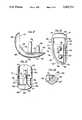
- FIG. 1is a side view of the knee joint prosthesis of the present invention with the femur and tibia shown in phantom.
- FIG. 2is a top plan view of the tibial prosthesis component of the present invention.
- FIG. 3is a bottom plan view of the tibial prosthesis component of FIG. 2.
- FIG. 4is a cross-section of the tibial prosthesis component taken along line 4--4 of FIG. 2.
- FIG. 5is an enlarged fragmentary view taken along line 5--5 of FIG. 4.
- FIG. 6is a broken side view of the tibial prosthesis component with a bearing insert shown in phantom.
- FIG. 7is a top view of a bearing insert of the present invention.
- FIG. 8is a section of the bearing insert taken along line 8--8 of FIG. 7.
- FIG. 9is a bottom plan view of another embodiment of the tibial prosthesis component of the present invention.
- FIG. 10is a side view of a further embodiment of the tibial prosthesis component of the present invention.
- FIG. 11is a side view of the femoral prosthesis component of the present invention.
- FIG. 12is a top view of the femoral prosthesis component of FIG. 11.
- FIG. 13is an anterior view of the femoral prosthesis component of FIG. 11.
- FIG. 14is an enlarged fragmentary view in section taken along line 14--14 of FIG. 11.
- the present inventionrelates to prostheses for implant in the body and is particularly described in connection wit a prosthesis or implant for the knee joint.
- a preferred embodiment for a knee joint prostheses implant according to the present inventionis shown in FIG. 1 and includes a tibial prosthesis component 12, a femoral prosthesis component 14 and a bearing insert 60.
- the tibial component 12is affixed to a suitably prepared site on the upper plateau 16 of the tibia 18, shown in phantom.
- the femoral component 14is affixed to a suitably prepared site on a condyle 20 of a femur 22, shown in phantom.
- FIGS. 2-6show a preferred embodiment of the tibial component 12 including a body 24 which, viewed from the top, has a generally asymmetrical, D-shaped configuration with an arcuate side wall 26 joined to a generally planar side wall 28 via curved side wall sections 29.
- the body 24has a top or upper surface 30 connecting the upper edges of the planar side wall 28, the arcuate side wall 26 and the curved side wall sections 29.
- the bodyhas a bottom or fixation surface 32 connecting the lower edges of the planar side wall 28, the arcuate side wall 26 and the curved side wall sections 29.
- a cavity 34is formed in the top surface 30 of the body 24 defined by a planar cavity side wall 36 joined to a arcuate cavity side wall 38 by curved cavity wall end sections 40 and a cavity bottom wall 42 joining the lower edges of cavity side walls 36, 38 and 40.
- An inwardly tapered through hole 44is formed in the cavity bottom wall 42 and extends substantially perpendicularly through the body 24.
- each curved cavity wall end section 40has a lip 46 projecting from the curved cavity wall section into the interior of the cavity 34.
- the lip 46has a chamfered surface 48 extending downwardly from the top surface 30 of the body at an angle of approximately 45°.
- the surface 48terminates in a vertical cavity facing surface 50 which joins curved cavity wall section 40 via a horizontal surface 52.
- Curved cavity wall sections 40extend downwardly from horizontal surface 52 to cavity bottom wall 42 at an angle of approximately 20° toward the interior of the cavity 34 such that lips 46 form grooves in the side wall curved end sections 40.
- the top surface 30 of the body 24is generally flat except for a sloping surface 54 at an anterior portion extending from a straight edge 56 located on the top surface downwardly at an angle of approximately 30° with respect to the parallel top and bottom surfaces to meet the side walls of the body.
- a through hole 58is formed in the anterior portion to extend through the body from sloping surface 54 to bottom surface 32 at an angle of approximately 60° with respect to the bottom surface 32 and perpendicular to surface 54.
- the bodyhas an upper surface 68 joining the upper ends of the insert side walls 62, 64 and 66, while the lower ends of the side walls are joined by a lower surface 70.
- Upper surface 68is slightly concave when viewed from the side, as shown in FIGS. 6 and 8.
- Each curved end section 66is provided with a flexible protruding lip 72 extending upwardly and outwardly from the lower surface 70 toward the upper surface 68 at an angle of approximately 20° with respect to the end section 66, as best illustrated in FIG. 8, to terminate in an upper edge 73 spaced from the side wall curved end section 66.
- the insert 60has a configuration mating with the configuration of cavity 34 and is received in the cavity 34, as shown in phantom in FIG.
- the insert bottom surface 70resting on the cavity bottom wall 42, insert side walls 62, 64 and 66 in close abutment with the respective cavity side walls 36, 38 and 40 and the lips 72 engaged in the grooves beneath lips 46 to securely retain the insert in position within the cavity.
- a range of insertsranging in thickness, for example, from approximately 8 mm to 15 mm as measured from the insert upper surface 68 to the insert lower surface 70, is provided so that the proper fit can be attained.
- the upper surface 68 of the insertwill be elevated with respect to the top surface 30 of the tibial component body by varying amounts depending upon the thickness of the particular insert.
- the bearing insertis integrally fabricated in a unitary manner of ultrahigh high molecular weight polyethylene.
- the fixation surface 32 of the body 24has a recess 74 therein defined within the confines of the side walls 26, 28 and 29 of the body.
- a channel or portal 76connects the recess 74 to the exterior of the body and extends from the recess 74 through the arcuate side wall 26 at the anterior portion of the body.
- the recess 74 and the channel 76share a common end wall 78 which defines the depth to which the recess and channel extend above the bottom surface 32 into the interior of the body.
- a land 80 along the fixation surface 32isolates the through hole 44 from the recess 74, while a land 82 along the fixation surface 32 isolates the through hole 58 from the recess 74.
- a rim 84projects from the bottom surface 32 spaced from but following the curve of arcuate side wall 26 with an interruption at the location of channel 76. As is most clearly depicted in FIGS. 4 and 5, the rim 84 is triangular in cross-sectional configuration, with the apex of the triangle forming a sharp bottom most edge 86 for the body. The rim 84 defines a wall extending along the recess 74 and at least partially surrounding the recess.
- the tibial component 12is provided in a range of sizes, for example, with the dimension A of the body ranging from approximately 37.5 mm to approximately 54 mm and the dimension B ranging from approximately 21 mm to approximately 33 mm, as shown in FIG. 2, to accommodate a range of sizes for optimal coverage of the tibial plateau.
- the asymmetrical "D" configuration of the bodyfurther contributes to optimal tibial plateau coverage in order to present a contact area for the femoral component coinciding with that of a normal knee.
- the tibial component 12is particularly designed to be affixed to a suitably prepared tibial plateau through arthroscopic surgical techniques; however, the tibial component can be used in normal open surgery procedures for prosthetic knee replacement.
- the bodycan be grasped by an appropriate surgical instrument and placed in position on the tibial plateau with the bottom most edge 86 resting upon the tibial plateau.
- the bodyis affixed by a cancellous bone screw 88 inserted at an angle through hole 58 and into the anterior portion of the tibia as illustrated in FIG. 1.
- a second cancellous bone screw 90can be inserted through the body into the tibia via through hole 44 if desired.
- the recess 74 formed in the bottom surface 32 of the bodydefine, together with the tibial plateau, an enclosed cement receiving chamber which communicates with the exterior of the body through channel 76.
- a bone cementpreferably low viscosity methyl-methacrylate, is injected into the chamber through channel 76 to form a physical bond between the body and the tibial plateau. It can be seen, therefore, that the tibial component can properly be positioned prior to the application of cement and need not be moved or disturbed in any manner thereby assuring precise and accurate positioning.
- the cementcan be inserted in the cement receiving chamber by means of a needle or syringe to be compatible with arthroscopic techniques.
- the rim 84forms a seal around the cement receiving chamber with respect to the tibial plateau to augment filling of the cement receiving chamber, and the rim 84 penetrates the tibial surface to establish a seal preventing escape of cement from the chamber while the bottom surface 32 engages the tibial plateau. Additionally, the rim 84 stabilizes the position of the tibial component on the tibial plateau.
- the lands 80 and 82 along the bottom surface 32isolate the respective fixation screws from the cement so that the screws can be removed, if necessary.
- the bottom surface 32 and the wall 78 of recess 74are textured to enhance the interface between the body and the cement.
- the inventioncontemplates a right medial/left lateral orientation for the tibial component in addition to the left medial/right lateral illustrated herein.
- a suitable bearing insert 60can be inserted after the body has been implanted, or the insert 60 can be mounted in the body prior to implanting the body.
- FIG. 9Another embodiment of a tibial component according to the present invention is shown in FIG. 9 wherein a body 88 is essentially the same as body 24 except that through hole 44 has been eliminated and the recess 90 follows the arcuate wall 26, as does end wall 92.
- the body 88thus accommodates only a single screw which, due to its position at the anterior portion of the implant, provides sufficient fixation.
- FIG. 10A further embodiment of the present invention is shown in FIG. 10 and is essentially the same as the tibial component of FIG. 9 except that a post 96 depends from the end wall 92 of the recess 90 at substantially the same position as through hole 44 shown in FIG. 3.
- the post 96is intended to be inserted into a corresponding drilled hole in the tibial plateau.
- the post 96is tapered to allow a press fit into the corresponding hole.
- the femoral component 14 of the prosthesis of the present inventionis illustrated in FIG. 11-15 and includes a body 100 having a curved configuration defining an arcuate outer bearing surface 102 with an anterior or distal end 104 and a posterior end 106.
- the bearing surface 102is generally polycentric, that is, the surface lies on arcs of circles having more than one center and more than one radius to approximate the natural articulating surface of a femoral condyle.
- the posterior end 106curves somewhat sharply while the anterior end 104 curves somewhat gradually. In other words, the radius of an imaginary circle in which the anterior end 104 lies is greater than the radius of an imaginary circle in which the posterior end 106 lies.
- Body 100further includes an inner fixation surface which joins the bearing surface 102 at side and end edges.
- the fixation surfaceincludes a planar posterior section 118, a planar chamfer section 120 and a planar distal section 122.
- the posterior and distal sections 118 and 122are oriented substantially perpendicular with respect to each other, while chamfer section 120 is oriented at an angle of substantially 45° with respect to the posterior and distal sections.
- the body 100has a generally straight medial side edge 110 and a generally straight lateral side edge 112 parallel to edge 110 but about one half the length of the edge 110.
- the side edge 112is joined to side edge 110 via a generally polycentric curved edge 114.
- An arcuate posterior edge 116joins the opposite ends of the side edges 110 and 112.
- Side edge 110extends along the sides of the posterior, chamfer and distal sections of the fixation surface.
- Side edge 112extends along the sides of the posterior and chamfer sections and along a portion of the side of the distal section, the curved edge 114 extending along the remaining portion of the side of the distal section.
- a recess 124is formed in the chamfer section 120 and the distal section 122 of the fixation surface.
- a side wall 126 of the recess 124generally follows the side edges 110, 112 and 114 of the body 100, running generally parallel thereto but separated therefrom by a portion of the fixation surface.
- the recessis provided with a bottom surface 128 and terminates along a bottom edge 130 of the posterior section 118.
- a channel 132is formed in the bottom surface 128 of the recess 124 3 extending generally parallel to the side edge 110 of the body 100 in the distal section 122 and through the curved side edge 114 of the body to establish communication with the exterior.
- Posts 136 and 138project upwardly substantially perpendicular to bottom surface 128, preferably at an inclination of 5° from the plane of the posterior section 118.
- the posts 136 and 138are generally cone-shaped and have respective tapered top ends 140 and 142. As depicted in FIG. 11, the post 136 is longer than the post 138, the post 138 being around two-thirds the length of post 136.
- a rim 144projects from the fixation surface, spaced from but lying generally parallel to side edges 110, 112 and 114 of the body 100. As can be seen in FIG.
- the rim 144also lies generally parallel to the side wall 126 of the recess 124 so as to at least partially surround the recess 124 along the chamfer section 120 and the distal section 122.
- the rim 144is preferably triangular in cross-sectional configuration to provide a relatively sharp edge 148 as was discussed in connection with rim 84 for the tibial component 12 and as shown in FIG. 14.
- a semi-circular indentation 150is provided on each side of the body 100 in distal section 122 proximate side edges 110 and 112 as shown in FIGS. 11, 12 and 13.
- the femoral component 14is adapted to be positioned on a condylar surface of the femur after the surface has been suitably cut and shaped to conform to the fixation surface of 4 the body 100.
- the femoral componentmay be positioned by means of open or arthroscopic surgical techniques with the indentations 150 engaged by a surgical tool for placement of the femoral component on the prepared femoral condyle.
- the posts 136 and 138are fitted into drilled holes in the cut distal end of the femoral condyle, the tapered upper ends 140 and 142 of the posts allowing for a press fit.
- the rim 144penetrates the bone to enhance securement and forms a seal with respect to the bone around the cement receiving chamber formed by the recess 124 and the surface of the bone.
- Cementis introduced into the chamber through the channel 132 by means of a syringe, a needle or the like as discussed in connection with the tibial component.
- the rim 144inhibits rotation of the femoral component as do the posts 136 and 138.
- the fixation surface and the recess bottom surface 128are textured to enhance the interface between the femoral component and the cement.
- the tibial and femoral componentsare preferably fabricated of metal, the preferred material for the tibial component being implant grade titanium, and for the femoral component cobalt-chromium.
- the surface 102 of the femoral componentcooperates with the concave surface 68 of bearing insert 60 to allow the same freedom of movement afforded by a healthy knee.
- the non-metallic insert 60provides a bearing surface for the metallic femoral component similar to the cartilage in a natural knee joint.
- the plastic material from which the insert is fabricatedprovides a low coefficient of friction between the contacting surfaces and minimizes the rate of wear of the contacting surfaces of the components.
- the femoral componentbe available in a number of sizes, and in right medial/left lateral and left medial/right lateral versions to prevent interference with the patella.
- the knee joint prosthesis of the present inventioncan be used in conventional open, total knee replacement surgical procedures but is particularly useful for implant using arthroscopic surgical techniques due to the simplified cementing procedures and the stability permitted by the tibial and femoral prosthesis components coupled with the modular nature thereof and the use of bearing inserts of varying sizes to produce desired tibial thicknesses or heights.
- Method and apparatus for implant of the knee joint prosthesis of the present inventionare disclosed in an application filed concurrently herewith by the same inventors, entitled “Methods and Apparatus for Arthroscopic Prosthetic Knee Replacement", the disclosure of which is incorporated herein by reference.
Landscapes
- Health & Medical Sciences (AREA)
- Orthopedic Medicine & Surgery (AREA)
- Physical Education & Sports Medicine (AREA)
- Cardiology (AREA)
- Oral & Maxillofacial Surgery (AREA)
- Transplantation (AREA)
- Engineering & Computer Science (AREA)
- Biomedical Technology (AREA)
- Heart & Thoracic Surgery (AREA)
- Vascular Medicine (AREA)
- Life Sciences & Earth Sciences (AREA)
- Animal Behavior & Ethology (AREA)
- General Health & Medical Sciences (AREA)
- Public Health (AREA)
- Veterinary Medicine (AREA)
- Prostheses (AREA)
Abstract
Description
Claims (10)
Priority Applications (1)
| Application Number | Priority Date | Filing Date | Title |
|---|---|---|---|
| US07/773,408US5207711A (en) | 1990-01-08 | 1991-10-09 | Knee joint prosthesis |
Applications Claiming Priority (2)
| Application Number | Priority Date | Filing Date | Title |
|---|---|---|---|
| US07/462,528US5171276A (en) | 1990-01-08 | 1990-01-08 | Knee joint prosthesis |
| US07/773,408US5207711A (en) | 1990-01-08 | 1991-10-09 | Knee joint prosthesis |
Related Parent Applications (1)
| Application Number | Title | Priority Date | Filing Date |
|---|---|---|---|
| US07/462,528DivisionUS5171276A (en) | 1990-01-08 | 1990-01-08 | Knee joint prosthesis |
Publications (1)
| Publication Number | Publication Date |
|---|---|
| US5207711Atrue US5207711A (en) | 1993-05-04 |
Family
ID=27040372
Family Applications (1)
| Application Number | Title | Priority Date | Filing Date |
|---|---|---|---|
| US07/773,408Expired - LifetimeUS5207711A (en) | 1990-01-08 | 1991-10-09 | Knee joint prosthesis |
Country Status (1)
| Country | Link |
|---|---|
| US (1) | US5207711A (en) |
Cited By (69)
| Publication number | Priority date | Publication date | Assignee | Title |
|---|---|---|---|---|
| US5344460A (en)* | 1992-10-30 | 1994-09-06 | Encore Orthopedics, Inc. | Prosthesis system |
| US5474559A (en)* | 1993-07-06 | 1995-12-12 | Zimmer, Inc. | Femoral milling instrumentation for use in total knee arthroplasty with optional cutting guide attachment |
| US5593411A (en)* | 1995-03-13 | 1997-01-14 | Zimmer, Inc. | Orthopaedic milling guide for milling intersecting planes |
| US5601563A (en)* | 1995-08-25 | 1997-02-11 | Zimmer, Inc. | Orthopaedic milling template with attachable cutting guide |
| US5653714A (en)* | 1996-02-22 | 1997-08-05 | Zimmer, Inc. | Dual slide cutting guide |
| US5658293A (en)* | 1995-10-10 | 1997-08-19 | Zimmer, Inc. | Guide platform associated with intramedullary rod |
| US5702461A (en)* | 1994-10-27 | 1997-12-30 | Biomedical Engineering Trust I | Prosthesis fixturing device |
| US5735904A (en)* | 1995-07-05 | 1998-04-07 | Pappas; Michael J. | Spacer for establishng prosthetic gap and ligamentous tension |
| US5743915A (en)* | 1993-07-06 | 1998-04-28 | Zimmer, Inc. | Femoral milling instrumentation for use in total knee arthoroplasty with optional cutting guide attachment |
| US5766255A (en)* | 1996-12-23 | 1998-06-16 | Johnson & Johnson Professional, Inc. | Modular joint prosthesis stabilization and augmentation system |
| WO1999001090A1 (en)* | 1997-07-04 | 1999-01-14 | Eska Implants Gmbh & Co. | Shankless knee joint endoprosthesis |
| DE19728636C1 (en)* | 1997-07-04 | 1999-03-11 | Eska Implants Gmbh & Co | Knee joint endoprosthesis with femur and tibia parts |
| US6059831A (en)* | 1999-03-31 | 2000-05-09 | Biomet, Inc. | Method of implanting a uni-condylar knee prosthesis |
| US6165221A (en)* | 1996-11-14 | 2000-12-26 | Plus Endoprothetik Ag | Implant |
| US6299645B1 (en) | 1999-07-23 | 2001-10-09 | William S. Ogden | Dove tail total knee replacement unicompartmental |
| US6494914B2 (en) | 2000-12-05 | 2002-12-17 | Biomet, Inc. | Unicondylar femoral prosthesis and instruments |
| US6503280B2 (en) | 2000-12-26 | 2003-01-07 | John A. Repicci | Prosthetic knee and method of inserting |
| US6673114B2 (en) | 2000-05-03 | 2004-01-06 | Smith & Nephew, Inc. | Multi modular trialing system and instrumentation |
| US20050125068A1 (en)* | 2003-12-05 | 2005-06-09 | Howmedica Osteonics Corp. | Orthopedic implant with angled pegs |
| US20050137708A1 (en)* | 2003-12-23 | 2005-06-23 | Ron Clark | Device and method of arthroscopic knee joint resurfacing |
| US20050177169A1 (en)* | 2004-02-06 | 2005-08-11 | Synvasive Technology, Inc. | Dynamic knee balancer |
| US20050203629A1 (en)* | 2004-02-26 | 2005-09-15 | George Cipolletti | Modular knee prosthesis |
| US6953479B2 (en) | 2001-07-16 | 2005-10-11 | Smith & Nephew, Inc. | Orthopedic implant extension |
| US20060100714A1 (en)* | 2003-04-02 | 2006-05-11 | Ortho Development Corporation | Tibial augment connector |
| US20060173546A1 (en)* | 2000-07-18 | 2006-08-03 | Biomet Manufacturing Corp. | Elbow prosthesis |
| US20060235537A1 (en)* | 2005-04-18 | 2006-10-19 | Accin Corporation | Unicondylar knee implant |
| US20070032876A1 (en)* | 2005-08-05 | 2007-02-08 | Ron Clark | Knee joint prosthesis |
| US20090018560A1 (en)* | 2007-04-20 | 2009-01-15 | Woodwelding Ag | Method for fastening an implant to bone tissue and corresponding implant system |
| US7628817B1 (en) | 2006-12-14 | 2009-12-08 | Howmedica Osteonics Corp. | Soft tissue deflection at a prosthetic joint |
| US20090306670A1 (en)* | 2005-04-18 | 2009-12-10 | Uni-Knee, Llc | Unicondylar Knee Instrument System |
| US20090326544A1 (en)* | 2008-06-27 | 2009-12-31 | Ryan Chessar | Knee ligament balancer |
| US20100087928A1 (en)* | 2000-07-18 | 2010-04-08 | Graham Thomas J | Elbow Prosthesis |
| US20100179661A1 (en)* | 2000-07-18 | 2010-07-15 | Biomet Manufacturing Corp. | Elbow prosthesis |
| US20100222887A1 (en)* | 2000-07-18 | 2010-09-02 | Biomet Manufacturing Corp. | Elbow Prosthesis |
| US7799084B2 (en) | 2002-10-23 | 2010-09-21 | Mako Surgical Corp. | Modular femoral component for a total knee joint replacement for minimally invasive implantation |
| US20100249658A1 (en)* | 2009-03-31 | 2010-09-30 | Sherman Jason T | Device and method for determining force of a knee joint |
| US7896924B1 (en) | 2008-01-09 | 2011-03-01 | Howmedica Osteonics Corp. | Unicondylar femoral prosthetic implant component |
| US20110125276A1 (en)* | 2000-04-10 | 2011-05-26 | Biomet Manufacturing Corp. | Modular prosthesis and use thereof for replacing a radial head |
| US20110172781A1 (en)* | 2009-09-18 | 2011-07-14 | Biomet Manufacturing Corp. | Elbow prosthesis |
| US20110230972A1 (en)* | 2009-09-18 | 2011-09-22 | Biomet Manufacturing Corp. | Elbow resurfacing prosthesis |
| KR101119725B1 (en) | 2004-02-06 | 2012-03-23 | 신베이시브 테크놀로지 인코포레이티드 | Dynamic knee balancer |
| US8287601B2 (en) | 2010-09-30 | 2012-10-16 | Depuy Products, Inc. | Femoral component of a knee prosthesis having an angled cement pocket |
| US8317870B2 (en) | 2010-09-30 | 2012-11-27 | Depuy Products, Inc. | Tibial component of a knee prosthesis having an angled cement pocket |
| US8535382B2 (en) | 2000-04-10 | 2013-09-17 | Biomet Manufacturing, Llc | Modular radial head prostheses |
| US8556830B2 (en) | 2009-03-31 | 2013-10-15 | Depuy | Device and method for displaying joint force data |
| US8597210B2 (en) | 2009-03-31 | 2013-12-03 | Depuy (Ireland) | System and method for displaying joint force data |
| US8721568B2 (en) | 2009-03-31 | 2014-05-13 | Depuy (Ireland) | Method for performing an orthopaedic surgical procedure |
| US8740817B2 (en) | 2009-03-31 | 2014-06-03 | Depuy (Ireland) | Device and method for determining forces of a patient's joint |
| US8758355B2 (en) | 2004-02-06 | 2014-06-24 | Synvasive Technology, Inc. | Dynamic knee balancer with pressure sensing |
| CN104068948A (en)* | 2014-07-18 | 2014-10-01 | 山东威高骨科材料有限公司 | Single-condylus prosthesis |
| US8920509B2 (en) | 2000-04-10 | 2014-12-30 | Biomet Manufacturing, Llc | Modular radial head prosthesis |
| US8998995B2 (en) | 2000-07-18 | 2015-04-07 | Biomet Manufacturing, Llc | Elbow prosthesis |
| US9039779B2 (en) | 2013-03-13 | 2015-05-26 | Biomet Manufacturing, Llc | Adjustable lateral articulating condyle |
| US9241801B1 (en)* | 2011-02-22 | 2016-01-26 | Todd R. Parry | Joint Arthroplasty |
| US9381011B2 (en) | 2012-03-29 | 2016-07-05 | Depuy (Ireland) | Orthopedic surgical instrument for knee surgery |
| US20160235549A1 (en)* | 2006-03-09 | 2016-08-18 | Woodwelding Ag | Method of implanting a contact implant |
| CN105877880A (en)* | 2015-02-13 | 2016-08-24 | 花世源 | Artificial knee joint and tibia component and femur component thereof |
| US9545459B2 (en) | 2012-03-31 | 2017-01-17 | Depuy Ireland Unlimited Company | Container for surgical instruments and system including same |
| US20180028323A1 (en)* | 2016-07-27 | 2018-02-01 | Howmedica Osteonics Corp. | Low profile tibial baseplate with fixation members |
| US10070973B2 (en) | 2012-03-31 | 2018-09-11 | Depuy Ireland Unlimited Company | Orthopaedic sensor module and system for determining joint forces of a patient's knee joint |
| US10098761B2 (en) | 2012-03-31 | 2018-10-16 | DePuy Synthes Products, Inc. | System and method for validating an orthopaedic surgical plan |
| US10105242B2 (en) | 2011-09-07 | 2018-10-23 | Depuy Ireland Unlimited Company | Surgical instrument and method |
| US10206792B2 (en) | 2012-03-31 | 2019-02-19 | Depuy Ireland Unlimited Company | Orthopaedic surgical system for determining joint forces of a patients knee joint |
| CN112869918A (en)* | 2021-01-27 | 2021-06-01 | 邬黎平 | Knee joint prosthesis structure |
| US20210177604A1 (en)* | 2015-02-08 | 2021-06-17 | Hafez Mahmoud Alm Ei Din | Tool for custom-made instruments and implant for artificial knee joint of dogs |
| US20210282936A1 (en)* | 2017-07-28 | 2021-09-16 | Active Implants LLC | Two-Piece Floating Joint Replacement Device With A Rigid Backing Material |
| US11213400B2 (en) | 2012-05-07 | 2022-01-04 | Encore Medical, L.P. | Elbow prosthesis |
| US11357644B2 (en) | 2011-10-24 | 2022-06-14 | Synvasive Technology, Inc. | Knee balancing devices, systems and methods |
| CN116898640A (en)* | 2023-07-10 | 2023-10-20 | 佳木斯骨科医院有限公司 | Implantable lower limb prosthesis for knee joint replacement |
Citations (34)
| Publication number | Priority date | Publication date | Assignee | Title |
|---|---|---|---|---|
| US3852830A (en)* | 1973-02-15 | 1974-12-10 | Richards Mfg Co | Knee prosthesis |
| US3869731A (en)* | 1973-02-14 | 1975-03-11 | Univ California | Articulated two-part prosthesis replacing the knee joint |
| US3953899A (en)* | 1973-05-17 | 1976-05-04 | Chas. F. Thackray Limited | Knee arthroplasty |
| US3958278A (en)* | 1974-04-22 | 1976-05-25 | National Research Development Corporation | Endoprosthetic knee joint |
| US4000525A (en)* | 1975-08-21 | 1977-01-04 | The United States Of America As Represented By The Secretary Of The Navy | Ceramic prosthetic implant suitable for a knee joint plateau |
| US4034418A (en)* | 1975-05-26 | 1977-07-12 | The Governing Council Of The University Of Toronto | Artificial knee joint |
| USD245259S (en) | 1976-01-29 | 1977-08-02 | Zimmer U.S.A. Inc. | Tibial prosthesis |
| US4055862A (en)* | 1976-01-23 | 1977-11-01 | Zimmer Usa, Inc. | Human body implant of graphitic carbon fiber reinforced ultra-high molecular weight polyethylene |
| US4085466A (en)* | 1974-11-18 | 1978-04-25 | National Research Development Corporation | Prosthetic joint device |
| USD248771S (en) | 1976-08-31 | 1978-08-01 | Groth Jr Harry E | Tibial prosthesis |
| SU719625A1 (en)* | 1978-04-26 | 1980-03-05 | Центральный Ордена Трудового Красного Знамени Научно-Исследовательский Институт Травматологии И Ортопедии Им. Н.Н.Приорова | Artificial knee joint |
| US4193140A (en)* | 1975-12-19 | 1980-03-18 | Richards Manufacturing Company, Inc. | Knee prosthesis |
| US4207627A (en)* | 1979-01-18 | 1980-06-17 | Cloutier Jean Marie | Knee prosthesis |
| US4211228A (en)* | 1979-01-24 | 1980-07-08 | Cloutier Jean Marie | Multipurpose tibial template |
| US4219893A (en)* | 1977-09-01 | 1980-09-02 | United States Surgical Corporation | Prosthetic knee joint |
| US4274163A (en)* | 1979-07-16 | 1981-06-23 | The Regents Of The University Of California | Prosthetic fixation technique |
| US4309778A (en)* | 1979-07-02 | 1982-01-12 | Biomedical Engineering Corp. | New Jersey meniscal bearing knee replacement |
| US4340978A (en)* | 1979-07-02 | 1982-07-27 | Biomedical Engineering Corp. | New Jersey meniscal bearing knee replacement |
| US4355429A (en)* | 1979-01-26 | 1982-10-26 | Osteo Ag | Slide prosthesis for the knee joint |
| US4470158A (en)* | 1978-03-10 | 1984-09-11 | Biomedical Engineering Corp. | Joint endoprosthesis |
| US4531243A (en)* | 1982-10-05 | 1985-07-30 | Sulzer Brothers Limited | Artificial hip joint socket |
| US4711639A (en)* | 1984-09-11 | 1987-12-08 | S+G Implants Gmbh | Anchorage for tibia plates |
| US4714474A (en)* | 1986-05-12 | 1987-12-22 | Dow Corning Wright Corporation | Tibial knee joint prosthesis with removable articulating surface insert |
| US4714473A (en)* | 1985-07-25 | 1987-12-22 | Harrington Arthritis Research Center | Knee prosthesis |
| US4728332A (en)* | 1984-11-28 | 1988-03-01 | Albrektsson Bjoern | Artificial menisco-tibial joint |
| US4743261A (en)* | 1986-01-27 | 1988-05-10 | Epinette Jean Alain | Tibial component for unicompartmental knee prosthesis for a cementness implantation |
| US4769040A (en)* | 1986-11-18 | 1988-09-06 | Queen's University At Kingston | Tibial prosthesis |
| US4795468A (en)* | 1987-12-23 | 1989-01-03 | Zimmer, Inc. | Mechanism and method for locking a bearing insert to the base of a prosthetic implant |
| US4838891A (en)* | 1984-11-28 | 1989-06-13 | Branemark Per Ingvar | Joint prothesis |
| US4865607A (en)* | 1985-10-02 | 1989-09-12 | Ulrich Witzel | Tibial plate for a knee-joint endoprosthesis |
| US4891547A (en)* | 1985-11-13 | 1990-01-02 | Ims Ionen Mikrofabrikations Systeme Gesellschaft Gmbh | Particle or radiation beam mask and process for making same |
| US4892547A (en)* | 1988-02-03 | 1990-01-09 | Biomet, Inc. | Partially stabilized knee prosthesis |
| US4963152A (en)* | 1986-10-27 | 1990-10-16 | Intermedics Orthopedics, Inc. | Asymmetric prosthetic tibial component |
| US4979957A (en)* | 1989-09-11 | 1990-12-25 | Zimmer, Inc. | Textured prosthetic implant |
- 1991
- 1991-10-09USUS07/773,408patent/US5207711A/ennot_activeExpired - Lifetime
Patent Citations (34)
| Publication number | Priority date | Publication date | Assignee | Title |
|---|---|---|---|---|
| US3869731A (en)* | 1973-02-14 | 1975-03-11 | Univ California | Articulated two-part prosthesis replacing the knee joint |
| US3852830A (en)* | 1973-02-15 | 1974-12-10 | Richards Mfg Co | Knee prosthesis |
| US3953899A (en)* | 1973-05-17 | 1976-05-04 | Chas. F. Thackray Limited | Knee arthroplasty |
| US3958278A (en)* | 1974-04-22 | 1976-05-25 | National Research Development Corporation | Endoprosthetic knee joint |
| US4085466A (en)* | 1974-11-18 | 1978-04-25 | National Research Development Corporation | Prosthetic joint device |
| US4034418A (en)* | 1975-05-26 | 1977-07-12 | The Governing Council Of The University Of Toronto | Artificial knee joint |
| US4000525A (en)* | 1975-08-21 | 1977-01-04 | The United States Of America As Represented By The Secretary Of The Navy | Ceramic prosthetic implant suitable for a knee joint plateau |
| US4193140A (en)* | 1975-12-19 | 1980-03-18 | Richards Manufacturing Company, Inc. | Knee prosthesis |
| US4055862A (en)* | 1976-01-23 | 1977-11-01 | Zimmer Usa, Inc. | Human body implant of graphitic carbon fiber reinforced ultra-high molecular weight polyethylene |
| USD245259S (en) | 1976-01-29 | 1977-08-02 | Zimmer U.S.A. Inc. | Tibial prosthesis |
| USD248771S (en) | 1976-08-31 | 1978-08-01 | Groth Jr Harry E | Tibial prosthesis |
| US4219893A (en)* | 1977-09-01 | 1980-09-02 | United States Surgical Corporation | Prosthetic knee joint |
| US4470158A (en)* | 1978-03-10 | 1984-09-11 | Biomedical Engineering Corp. | Joint endoprosthesis |
| SU719625A1 (en)* | 1978-04-26 | 1980-03-05 | Центральный Ордена Трудового Красного Знамени Научно-Исследовательский Институт Травматологии И Ортопедии Им. Н.Н.Приорова | Artificial knee joint |
| US4207627A (en)* | 1979-01-18 | 1980-06-17 | Cloutier Jean Marie | Knee prosthesis |
| US4211228A (en)* | 1979-01-24 | 1980-07-08 | Cloutier Jean Marie | Multipurpose tibial template |
| US4355429A (en)* | 1979-01-26 | 1982-10-26 | Osteo Ag | Slide prosthesis for the knee joint |
| US4309778A (en)* | 1979-07-02 | 1982-01-12 | Biomedical Engineering Corp. | New Jersey meniscal bearing knee replacement |
| US4340978A (en)* | 1979-07-02 | 1982-07-27 | Biomedical Engineering Corp. | New Jersey meniscal bearing knee replacement |
| US4274163A (en)* | 1979-07-16 | 1981-06-23 | The Regents Of The University Of California | Prosthetic fixation technique |
| US4531243A (en)* | 1982-10-05 | 1985-07-30 | Sulzer Brothers Limited | Artificial hip joint socket |
| US4711639A (en)* | 1984-09-11 | 1987-12-08 | S+G Implants Gmbh | Anchorage for tibia plates |
| US4838891A (en)* | 1984-11-28 | 1989-06-13 | Branemark Per Ingvar | Joint prothesis |
| US4728332A (en)* | 1984-11-28 | 1988-03-01 | Albrektsson Bjoern | Artificial menisco-tibial joint |
| US4714473A (en)* | 1985-07-25 | 1987-12-22 | Harrington Arthritis Research Center | Knee prosthesis |
| US4865607A (en)* | 1985-10-02 | 1989-09-12 | Ulrich Witzel | Tibial plate for a knee-joint endoprosthesis |
| US4891547A (en)* | 1985-11-13 | 1990-01-02 | Ims Ionen Mikrofabrikations Systeme Gesellschaft Gmbh | Particle or radiation beam mask and process for making same |
| US4743261A (en)* | 1986-01-27 | 1988-05-10 | Epinette Jean Alain | Tibial component for unicompartmental knee prosthesis for a cementness implantation |
| US4714474A (en)* | 1986-05-12 | 1987-12-22 | Dow Corning Wright Corporation | Tibial knee joint prosthesis with removable articulating surface insert |
| US4963152A (en)* | 1986-10-27 | 1990-10-16 | Intermedics Orthopedics, Inc. | Asymmetric prosthetic tibial component |
| US4769040A (en)* | 1986-11-18 | 1988-09-06 | Queen's University At Kingston | Tibial prosthesis |
| US4795468A (en)* | 1987-12-23 | 1989-01-03 | Zimmer, Inc. | Mechanism and method for locking a bearing insert to the base of a prosthetic implant |
| US4892547A (en)* | 1988-02-03 | 1990-01-09 | Biomet, Inc. | Partially stabilized knee prosthesis |
| US4979957A (en)* | 1989-09-11 | 1990-12-25 | Zimmer, Inc. | Textured prosthetic implant |
Cited By (136)
| Publication number | Priority date | Publication date | Assignee | Title |
|---|---|---|---|---|
| US5344460A (en)* | 1992-10-30 | 1994-09-06 | Encore Orthopedics, Inc. | Prosthesis system |
| US5769855A (en)* | 1993-07-06 | 1998-06-23 | Zimmer Inc. | Femoral milling instrumentation for use in total knee arthroplasty with optional cutting guide attachment |
| US5474559A (en)* | 1993-07-06 | 1995-12-12 | Zimmer, Inc. | Femoral milling instrumentation for use in total knee arthroplasty with optional cutting guide attachment |
| US5743915A (en)* | 1993-07-06 | 1998-04-28 | Zimmer, Inc. | Femoral milling instrumentation for use in total knee arthoroplasty with optional cutting guide attachment |
| US5860981A (en)* | 1993-07-06 | 1999-01-19 | Dennis W. Burke | Guide for femoral milling instrumention for use in total knee arthroplasty |
| US5868797A (en)* | 1994-10-27 | 1999-02-09 | Biomedical Engineering Trust I | Prosthesis fixturing device |
| US5702461A (en)* | 1994-10-27 | 1997-12-30 | Biomedical Engineering Trust I | Prosthesis fixturing device |
| US5593411A (en)* | 1995-03-13 | 1997-01-14 | Zimmer, Inc. | Orthopaedic milling guide for milling intersecting planes |
| US5735904A (en)* | 1995-07-05 | 1998-04-07 | Pappas; Michael J. | Spacer for establishng prosthetic gap and ligamentous tension |
| US5601563A (en)* | 1995-08-25 | 1997-02-11 | Zimmer, Inc. | Orthopaedic milling template with attachable cutting guide |
| US5658293A (en)* | 1995-10-10 | 1997-08-19 | Zimmer, Inc. | Guide platform associated with intramedullary rod |
| US5653714A (en)* | 1996-02-22 | 1997-08-05 | Zimmer, Inc. | Dual slide cutting guide |
| US6165221A (en)* | 1996-11-14 | 2000-12-26 | Plus Endoprothetik Ag | Implant |
| US5766255A (en)* | 1996-12-23 | 1998-06-16 | Johnson & Johnson Professional, Inc. | Modular joint prosthesis stabilization and augmentation system |
| WO1999001090A1 (en)* | 1997-07-04 | 1999-01-14 | Eska Implants Gmbh & Co. | Shankless knee joint endoprosthesis |
| DE19728636C1 (en)* | 1997-07-04 | 1999-03-11 | Eska Implants Gmbh & Co | Knee joint endoprosthesis with femur and tibia parts |
| DE19745632C1 (en)* | 1997-07-04 | 1999-07-01 | Eska Implants Gmbh & Co | Stemless knee joint prosthesis with swiveling tibia plateau |
| US6245110B1 (en) | 1997-07-04 | 2001-06-12 | Eska Implants Gmbh & Co. | Shankless knee joint endoprosthesis |
| US6059831A (en)* | 1999-03-31 | 2000-05-09 | Biomet, Inc. | Method of implanting a uni-condylar knee prosthesis |
| US6299645B1 (en) | 1999-07-23 | 2001-10-09 | William S. Ogden | Dove tail total knee replacement unicompartmental |
| US20110125276A1 (en)* | 2000-04-10 | 2011-05-26 | Biomet Manufacturing Corp. | Modular prosthesis and use thereof for replacing a radial head |
| US9579208B2 (en) | 2000-04-10 | 2017-02-28 | Biomet Manufacturing, Llc | Modular radial head prosthesis |
| US8535382B2 (en) | 2000-04-10 | 2013-09-17 | Biomet Manufacturing, Llc | Modular radial head prostheses |
| US8425615B2 (en) | 2000-04-10 | 2013-04-23 | Biomet Manufacturing Corp. | Method and apparatus for adjusting height and angle for a radial head |
| US8366781B2 (en) | 2000-04-10 | 2013-02-05 | Biomet Manufacturing Corp. | Modular prosthesis and use thereof for replacing a radial head |
| US8920509B2 (en) | 2000-04-10 | 2014-12-30 | Biomet Manufacturing, Llc | Modular radial head prosthesis |
| US9333084B2 (en) | 2000-04-10 | 2016-05-10 | Biomet Manufacturing, Llc | Modular prosthesis and use thereof for replacing a radial head |
| US8114163B2 (en) | 2000-04-10 | 2012-02-14 | Biomet Manufacturing Corp. | Method and apparatus for adjusting height and angle for a radial head |
| US8110005B2 (en) | 2000-04-10 | 2012-02-07 | Biomet Manufacturing Corp. | Modular prosthesis and use thereof for replacing a radial head |
| US9439784B2 (en) | 2000-04-10 | 2016-09-13 | Biomet Manufacturing, Llc | Modular radial head prosthesis |
| US6673114B2 (en) | 2000-05-03 | 2004-01-06 | Smith & Nephew, Inc. | Multi modular trialing system and instrumentation |
| US20100222887A1 (en)* | 2000-07-18 | 2010-09-02 | Biomet Manufacturing Corp. | Elbow Prosthesis |
| US9901453B2 (en) | 2000-07-18 | 2018-02-27 | Encore Medical, L.P. | Elbow prosthesis |
| US8932362B2 (en) | 2000-07-18 | 2015-01-13 | Biomet Manufacturing, Llc | Elbow prosthesis |
| US10925742B2 (en) | 2000-07-18 | 2021-02-23 | Encore Medical, L.P. | Elbow prosthesis |
| US8998995B2 (en) | 2000-07-18 | 2015-04-07 | Biomet Manufacturing, Llc | Elbow prosthesis |
| US9561110B2 (en)* | 2000-07-18 | 2017-02-07 | Encore Medical, L.P. | Elbow prosthesis |
| US10792160B2 (en) | 2000-07-18 | 2020-10-06 | Encore Medical, L.P. | Elbow prosthesis |
| US8585768B2 (en) | 2000-07-18 | 2013-11-19 | Biomet Manufacturing, Llc | Elbow prosthesis |
| US10596006B2 (en) | 2000-07-18 | 2020-03-24 | Encore Medical, L.P. | Elbow prosthesis |
| US20060173546A1 (en)* | 2000-07-18 | 2006-08-03 | Biomet Manufacturing Corp. | Elbow prosthesis |
| US10226346B2 (en) | 2000-07-18 | 2019-03-12 | Encore Medical, L.P. | Elbow prosthesis |
| US10342665B2 (en) | 2000-07-18 | 2019-07-09 | Encore Medical, L.P. | Elbow prosthesis |
| US10231839B2 (en) | 2000-07-18 | 2019-03-19 | Encore Medical, L.P. | Elbow prosthesis |
| US20100087928A1 (en)* | 2000-07-18 | 2010-04-08 | Graham Thomas J | Elbow Prosthesis |
| US20100179661A1 (en)* | 2000-07-18 | 2010-07-15 | Biomet Manufacturing Corp. | Elbow prosthesis |
| US6494914B2 (en) | 2000-12-05 | 2002-12-17 | Biomet, Inc. | Unicondylar femoral prosthesis and instruments |
| US6503280B2 (en) | 2000-12-26 | 2003-01-07 | John A. Repicci | Prosthetic knee and method of inserting |
| US6726724B2 (en) | 2000-12-26 | 2004-04-27 | John A. Repicci | Prosthetic knee |
| US6953479B2 (en) | 2001-07-16 | 2005-10-11 | Smith & Nephew, Inc. | Orthopedic implant extension |
| US7799084B2 (en) | 2002-10-23 | 2010-09-21 | Mako Surgical Corp. | Modular femoral component for a total knee joint replacement for minimally invasive implantation |
| US8016891B2 (en) | 2003-04-02 | 2011-09-13 | Ortho Development Corporation | Tibial augment connector |
| US20060100714A1 (en)* | 2003-04-02 | 2006-05-11 | Ortho Development Corporation | Tibial augment connector |
| US7294149B2 (en)* | 2003-12-05 | 2007-11-13 | Howmedica Osteonics Corp. | Orthopedic implant with angled pegs |
| US20050125068A1 (en)* | 2003-12-05 | 2005-06-09 | Howmedica Osteonics Corp. | Orthopedic implant with angled pegs |
| US20050137708A1 (en)* | 2003-12-23 | 2005-06-23 | Ron Clark | Device and method of arthroscopic knee joint resurfacing |
| US20050177169A1 (en)* | 2004-02-06 | 2005-08-11 | Synvasive Technology, Inc. | Dynamic knee balancer |
| US8491589B2 (en) | 2004-02-06 | 2013-07-23 | Synvasive Technology, Inc. | Dynamic knee balancer with pressure sensing |
| WO2005076834A3 (en)* | 2004-02-06 | 2006-09-08 | Synvasive Technology Inc | Dynamic knee balancer |
| US20050267485A1 (en)* | 2004-02-06 | 2005-12-01 | Synvasive Technology, Inc. | Dynamic knee balancer with opposing adjustment mechanism |
| US7837691B2 (en) | 2004-02-06 | 2010-11-23 | Synvasive Technology, Inc. | Dynamic knee balancer with opposing adjustment mechanism |
| KR101119725B1 (en) | 2004-02-06 | 2012-03-23 | 신베이시브 테크놀로지 인코포레이티드 | Dynamic knee balancer |
| US8715290B2 (en) | 2004-02-06 | 2014-05-06 | Synvasive Technology, Inc. | Dynamic knee balancer with pressure sensing |
| US8758355B2 (en) | 2004-02-06 | 2014-06-24 | Synvasive Technology, Inc. | Dynamic knee balancer with pressure sensing |
| US10555822B2 (en) | 2004-02-06 | 2020-02-11 | Synvasive Technology, Inc. | Dynamic knee balancer with force or pressure sensing |
| US7442196B2 (en) | 2004-02-06 | 2008-10-28 | Synvasive Technology, Inc. | Dynamic knee balancer |
| US7578821B2 (en) | 2004-02-06 | 2009-08-25 | Synvasive Technology, Inc. | Dynamic knee balancer with pressure sensing |
| US20090287310A1 (en)* | 2004-02-06 | 2009-11-19 | Synvasive Technology, Inc. | Dynamic knee balancer with pressure sensing |
| US9572588B2 (en) | 2004-02-06 | 2017-02-21 | Synvasive Technology, Inc. | Dynamic knee balancer with force or pressure sensing |
| US20100262253A1 (en)* | 2004-02-26 | 2010-10-14 | Omni Life Science, Inc. | Modular Knee Prosthesis |
| US7753960B2 (en)* | 2004-02-26 | 2010-07-13 | Omni Life Science, Inc. | Modular knee prosthesis |
| US8277513B2 (en) | 2004-02-26 | 2012-10-02 | Omni Life Science, Inc. | Modular knee prosthesis |
| US20050203629A1 (en)* | 2004-02-26 | 2005-09-15 | George Cipolletti | Modular knee prosthesis |
| US20060235537A1 (en)* | 2005-04-18 | 2006-10-19 | Accin Corporation | Unicondylar knee implant |
| US7578850B2 (en) | 2005-04-18 | 2009-08-25 | Uni-Knee, Llc | Unicondylar knee implant |
| US20090306670A1 (en)* | 2005-04-18 | 2009-12-10 | Uni-Knee, Llc | Unicondylar Knee Instrument System |
| US8057478B2 (en) | 2005-04-18 | 2011-11-15 | Arthrex, Inc. | Unicondylar knee instrument system |
| US20070032876A1 (en)* | 2005-08-05 | 2007-02-08 | Ron Clark | Knee joint prosthesis |
| US7862619B2 (en) | 2005-08-05 | 2011-01-04 | Vot, Llc | Knee joint prosthesis |
| US10758372B2 (en)* | 2006-03-09 | 2020-09-01 | Woodwelding Ag | Method of implanting a contact implant |
| US20160235549A1 (en)* | 2006-03-09 | 2016-08-18 | Woodwelding Ag | Method of implanting a contact implant |
| US7628817B1 (en) | 2006-12-14 | 2009-12-08 | Howmedica Osteonics Corp. | Soft tissue deflection at a prosthetic joint |
| US9289301B2 (en) | 2007-04-20 | 2016-03-22 | Woodwelding Ag | Method for fastening an implant to bone tissue and corresponding implant system |
| US20090018560A1 (en)* | 2007-04-20 | 2009-01-15 | Woodwelding Ag | Method for fastening an implant to bone tissue and corresponding implant system |
| US8357201B2 (en)* | 2007-04-20 | 2013-01-22 | Woodwelding Ag | Method for fastening an implant to bone tissue and corresponding implant system |
| US7896924B1 (en) | 2008-01-09 | 2011-03-01 | Howmedica Osteonics Corp. | Unicondylar femoral prosthetic implant component |
| US8197489B2 (en) | 2008-06-27 | 2012-06-12 | Depuy Products, Inc. | Knee ligament balancer |
| US8562617B2 (en) | 2008-06-27 | 2013-10-22 | DePuy Synthes Products, LLC | Knee ligament balancer |
| US20090326544A1 (en)* | 2008-06-27 | 2009-12-31 | Ryan Chessar | Knee ligament balancer |
| US8740817B2 (en) | 2009-03-31 | 2014-06-03 | Depuy (Ireland) | Device and method for determining forces of a patient's joint |
| US8551023B2 (en) | 2009-03-31 | 2013-10-08 | Depuy (Ireland) | Device and method for determining force of a knee joint |
| US20100249658A1 (en)* | 2009-03-31 | 2010-09-30 | Sherman Jason T | Device and method for determining force of a knee joint |
| US9538953B2 (en) | 2009-03-31 | 2017-01-10 | Depuy Ireland Unlimited Company | Device and method for determining force of a knee joint |
| US8721568B2 (en) | 2009-03-31 | 2014-05-13 | Depuy (Ireland) | Method for performing an orthopaedic surgical procedure |
| US8556830B2 (en) | 2009-03-31 | 2013-10-15 | Depuy | Device and method for displaying joint force data |
| US9649119B2 (en) | 2009-03-31 | 2017-05-16 | Depuy Ireland Unlimited Company | Method for performing an orthopaedic surgical procedure |
| US8597210B2 (en) | 2009-03-31 | 2013-12-03 | Depuy (Ireland) | System and method for displaying joint force data |
| US9034050B2 (en) | 2009-09-18 | 2015-05-19 | Biomet Manufacturing, Llc | Elbow prosthesis |
| US10945851B2 (en) | 2009-09-18 | 2021-03-16 | Encore Medical, Lp | Elbow prosthesis |
| US10149766B2 (en) | 2009-09-18 | 2018-12-11 | Encore Medical, Lp | Elbow prosthesis |
| US20110230972A1 (en)* | 2009-09-18 | 2011-09-22 | Biomet Manufacturing Corp. | Elbow resurfacing prosthesis |
| US20110172781A1 (en)* | 2009-09-18 | 2011-07-14 | Biomet Manufacturing Corp. | Elbow prosthesis |
| US8287601B2 (en) | 2010-09-30 | 2012-10-16 | Depuy Products, Inc. | Femoral component of a knee prosthesis having an angled cement pocket |
| US9724202B2 (en) | 2010-09-30 | 2017-08-08 | Depuy Ireland Unlimited Company | Femoral component of a knee prosthesis having an angled cement pocket |
| US8317870B2 (en) | 2010-09-30 | 2012-11-27 | Depuy Products, Inc. | Tibial component of a knee prosthesis having an angled cement pocket |
| US8845746B2 (en) | 2010-09-30 | 2014-09-30 | Depuy (Ireland) | Femoral component of a knee prosthesis having an angled posterior cement pocket |
| US9241801B1 (en)* | 2011-02-22 | 2016-01-26 | Todd R. Parry | Joint Arthroplasty |
| US10105242B2 (en) | 2011-09-07 | 2018-10-23 | Depuy Ireland Unlimited Company | Surgical instrument and method |
| US11357644B2 (en) | 2011-10-24 | 2022-06-14 | Synvasive Technology, Inc. | Knee balancing devices, systems and methods |
| US10485530B2 (en) | 2012-03-29 | 2019-11-26 | Depuy Ireland Unlimited Company | Orthopedic surgical instrument for knee surgery |
| US11589857B2 (en) | 2012-03-29 | 2023-02-28 | Depuy Ireland Unlimited Company | Orthopedic surgical instrument for knee surgery |
| US9381011B2 (en) | 2012-03-29 | 2016-07-05 | Depuy (Ireland) | Orthopedic surgical instrument for knee surgery |
| US12161314B2 (en) | 2012-03-29 | 2024-12-10 | Depuy Ireland Unlimited Company | Orthopedic surgical instrument for knee surgery |
| US11051955B2 (en) | 2012-03-31 | 2021-07-06 | DePuy Synthes Products, Inc. | System and method for validating an orthopaedic surgical plan |
| US9545459B2 (en) | 2012-03-31 | 2017-01-17 | Depuy Ireland Unlimited Company | Container for surgical instruments and system including same |
| US10206792B2 (en) | 2012-03-31 | 2019-02-19 | Depuy Ireland Unlimited Company | Orthopaedic surgical system for determining joint forces of a patients knee joint |
| US12324752B2 (en) | 2012-03-31 | 2025-06-10 | Depuy Ireland Unlimited Company | Orthopaedic surgical system for determining joint forces of a patient's knee joint |
| US10098761B2 (en) | 2012-03-31 | 2018-10-16 | DePuy Synthes Products, Inc. | System and method for validating an orthopaedic surgical plan |
| US10070973B2 (en) | 2012-03-31 | 2018-09-11 | Depuy Ireland Unlimited Company | Orthopaedic sensor module and system for determining joint forces of a patient's knee joint |
| US11096801B2 (en) | 2012-03-31 | 2021-08-24 | Depuy Ireland Unlimited Company | Orthopaedic surgical system for determining joint forces of a patient's knee joint |
| US11213400B2 (en) | 2012-05-07 | 2022-01-04 | Encore Medical, L.P. | Elbow prosthesis |
| US9039779B2 (en) | 2013-03-13 | 2015-05-26 | Biomet Manufacturing, Llc | Adjustable lateral articulating condyle |
| CN104068948A (en)* | 2014-07-18 | 2014-10-01 | 山东威高骨科材料有限公司 | Single-condylus prosthesis |
| US12121445B2 (en)* | 2015-02-08 | 2024-10-22 | Mahmoud Hafez | Tool for custom-made instruments and implant for artificial knee joint of dogs |
| US20210177604A1 (en)* | 2015-02-08 | 2021-06-17 | Hafez Mahmoud Alm Ei Din | Tool for custom-made instruments and implant for artificial knee joint of dogs |
| CN106031667A (en)* | 2015-02-13 | 2016-10-19 | 花世源 | Artificial knee joint and tibia component and femur component thereof |
| CN105877880A (en)* | 2015-02-13 | 2016-08-24 | 花世源 | Artificial knee joint and tibia component and femur component thereof |
| US20180028323A1 (en)* | 2016-07-27 | 2018-02-01 | Howmedica Osteonics Corp. | Low profile tibial baseplate with fixation members |
| US10231840B2 (en)* | 2016-07-27 | 2019-03-19 | Howmedica Osteonics Corp. | Low profile tibial baseplate with fixation members |
| USD884179S1 (en) | 2016-07-27 | 2020-05-12 | Howmedica Osteonics Corp. | Tibial baseplate with fixation members |
| US20210282936A1 (en)* | 2017-07-28 | 2021-09-16 | Active Implants LLC | Two-Piece Floating Joint Replacement Device With A Rigid Backing Material |
| US11903837B2 (en)* | 2017-07-28 | 2024-02-20 | Active Implants LLC | Two-piece floating joint replacement device with a rigid backing material |
| CN112869918A (en)* | 2021-01-27 | 2021-06-01 | 邬黎平 | Knee joint prosthesis structure |
| CN112869918B (en)* | 2021-01-27 | 2025-04-01 | 邬黎平 | Knee prosthesis structure |
| CN116898640A (en)* | 2023-07-10 | 2023-10-20 | 佳木斯骨科医院有限公司 | Implantable lower limb prosthesis for knee joint replacement |
| CN116898640B (en)* | 2023-07-10 | 2024-05-24 | 佳木斯骨科医院有限公司 | Implantable lower limb prosthesis for knee joint replacement |
Similar Documents
| Publication | Publication Date | Title |
|---|---|---|
| US5207711A (en) | Knee joint prosthesis | |
| US5201768A (en) | Prosthesis for implant on the tibial plateau of the knee | |
| US5171276A (en) | Knee joint prosthesis | |
| US8226727B2 (en) | Femoral prosthesis | |
| US6139581A (en) | Posterior compensation tibial tray | |
| US4808185A (en) | Tibial prosthesis, template and reamer | |
| US5383937A (en) | Recessed patellar prosthesis | |
| US4205400A (en) | Metallo-polymeric prosthesis with cavitied interconnection | |
| EP0183669B1 (en) | Joint prosthesis | |
| US3987500A (en) | Surgically implantable total ankle prosthesis | |
| EP1480582B1 (en) | Patello-femoral joint replacement | |
| CA1298039C (en) | Prosthesis for tibial component of knee joint | |
| EP3400911B1 (en) | Tibial tray with fixation features | |
| US20050154470A1 (en) | Modular phrosthesis assembly including tapered adjustments | |
| US7862619B2 (en) | Knee joint prosthesis | |
| US20210338448A1 (en) | Talar Ankle Implant | |
| CN118119362A (en) | Tibial component for endoprosthesis knee implants, kits and instruments for tibial component, and methods of use |
Legal Events
| Date | Code | Title | Description |
|---|---|---|---|
| STCF | Information on status: patent grant | Free format text:PATENTED CASE | |
| FPAY | Fee payment | Year of fee payment:4 | |
| AS | Assignment | Owner name:ZIMMER, INC., INDIANA Free format text:ASSIGNMENT OF ASSIGNORS INTEREST;ASSIGNORS:CASPARI, RICHARD B.;CASPARI ENTERPRISES, INC.;REEL/FRAME:009798/0284 Effective date:19990211 | |
| AS | Assignment | Owner name:BRISTOL-MYERS SQIBB COMPANY, NEW YORK Free format text:ASSIGNMENT OF ASSIGNORS INTEREST;ASSIGNOR:ZIMMER, INC.;REEL/FRAME:009833/0170 Effective date:19990316 | |
| FPAY | Fee payment | Year of fee payment:8 | |
| AS | Assignment | Owner name:ZIMMER, INC., INDIANA Free format text:ASSIGNMENT OF ASSIGNORS INTEREST;ASSIGNOR:BRISTOL-MYERS SQUIBB COMPANY;REEL/FRAME:012729/0494 Effective date:20020114 | |
| AS | Assignment | Owner name:ZIMMER TECHNOLOGY, INC., ILLINOIS Free format text:ASSIGNMENT OF ASSIGNORS INTEREST;ASSIGNOR:ZIMMER, INC.;REEL/FRAME:013862/0766 Effective date:20020628 | |
| FPAY | Fee payment | Year of fee payment:12 |