US5207684A - Sheath for shunt placement for hydrocephalus - Google Patents
Sheath for shunt placement for hydrocephalusDownload PDFInfo
- Publication number
- US5207684A US5207684AUS07/867,826US86782692AUS5207684AUS 5207684 AUS5207684 AUS 5207684AUS 86782692 AUS86782692 AUS 86782692AUS 5207684 AUS5207684 AUS 5207684A
- Authority
- US
- United States
- Prior art keywords
- shunt
- tubular member
- cutting element
- brain
- distal end
- Prior art date
- Legal status (The legal status is an assumption and is not a legal conclusion. Google has not performed a legal analysis and makes no representation as to the accuracy of the status listed.)
- Expired - Lifetime
Links
Images

Classifications
- A—HUMAN NECESSITIES
- A61—MEDICAL OR VETERINARY SCIENCE; HYGIENE
- A61B—DIAGNOSIS; SURGERY; IDENTIFICATION
- A61B18/00—Surgical instruments, devices or methods for transferring non-mechanical forms of energy to or from the body
- A61B18/04—Surgical instruments, devices or methods for transferring non-mechanical forms of energy to or from the body by heating
- A61B18/08—Surgical instruments, devices or methods for transferring non-mechanical forms of energy to or from the body by heating by means of electrically-heated probes
- A61B18/082—Probes or electrodes therefor
- A—HUMAN NECESSITIES
- A61—MEDICAL OR VETERINARY SCIENCE; HYGIENE
- A61M—DEVICES FOR INTRODUCING MEDIA INTO, OR ONTO, THE BODY; DEVICES FOR TRANSDUCING BODY MEDIA OR FOR TAKING MEDIA FROM THE BODY; DEVICES FOR PRODUCING OR ENDING SLEEP OR STUPOR
- A61M27/00—Drainage appliance for wounds or the like, i.e. wound drains, implanted drains
- A61M27/002—Implant devices for drainage of body fluids from one part of the body to another
- A61M27/006—Cerebrospinal drainage; Accessories therefor, e.g. valves
- A—HUMAN NECESSITIES
- A61—MEDICAL OR VETERINARY SCIENCE; HYGIENE
- A61B—DIAGNOSIS; SURGERY; IDENTIFICATION
- A61B18/00—Surgical instruments, devices or methods for transferring non-mechanical forms of energy to or from the body
- A61B2018/00982—Surgical instruments, devices or methods for transferring non-mechanical forms of energy to or from the body combined with or comprising means for visual or photographic inspections inside the body, e.g. endoscopes
Definitions
- the present inventionrelates generally to surgical instruments, and more particularly to neurosurgery tools.
- Hydrocephalusfamiliarly known as water on the brain, is an affliction which affects many people, including children.
- One of the symptoms of this serious maladyis increased fluid pressure on the brain of the victim, which, unless relieved, can result in excruciating pain, and can potentially cause brain damage to the victim.
- Hydrocephaluscauses a slow, continuous build-up of fluid pressure on the brain. More specifically, in a patient afflicted with hydrocephalus, excess body fluid slowly and continuously accumulates between the ventricles of the brain. To extract the excess body fluid from between the ventricles of the brain and thereby relieve the fluid pressure on the brain, techniques have been developed for establishing a pathway for fluid communication from the area of accumulated fluid to an area external to the cranial cavity.
- a long, slender catheter known as a "shunt"is advanced through a small entry site in the neck of a patient who is afflicted with hydrocephalus, and a distal end segment of the shunt is positioned between the ventricles of the brain.
- the end of the shunt that is opposite to the distal end segmentis positioned in the chest cavity of the patient.
- a plurality of small holesare formed in the distal end segment of the shunt, and fluid that accumulates in the brain enters the holes and drains through the shunt into the chest cavity of the patient, thereby relieving the fluid pressure on the brain.
- the small holes in the distal end segment of the shuntcan become clogged, thereby impeding the draining of excess fluid from the cranial cavity. More specifically, a portion of the brain known as the choroid plexus can grow into the holes of the distal end segment of the shunt and clog the holes. When this occurs, it is necessary to remove the shunt from the brain and replace the shunt with another unclogged shunt.
- the clogged shuntcannot simply be pulled out of the brain, with portions of the choroid plexus still attached to it, without risking damage to the brain.
- a shuntbecomes clogged, it is necessary to perform a relatively invasive surgical procedure to gain access to the distal end segment of the shunt and gently cut away the ingrown portions of the choroid plexus.
- itis desireable to avoid performing invasive procedures on the brain, to avoid undue risk of brain damage and infection, and to reduce overall patient discomfort.
- a device for withdrawing a shunt from the brain of a patientincludes a tubular member that is slidably engageable with the shunt in a surrounding relationship therewith.
- the tubular memberhas a distal end segment, and a cutting element is positioned on the distal end segment for selectively cutting tissue which is adjacent to the cutting element as the tubular member is advanced over the shunt.
- the cutting elementis electrically resistive, and a source of electricity is electrically connected to the cutting element for selectively energizing the cutting element to cut tissue.
- the cutting elementcan advantageously be made of metal or ceramic.
- the cutting elementis cylindrically-shaped, to establish an electrical monopole cutting element.
- the cutting elementhas first and second collars that conform to the shape of the tubular member and that are spaced apart from each other, to establish an electrical dipole cutting element.
- each collarhas first and second co-parallel straight edges, and the collars are positioned on the tubular member with the first edge of one collar closely spaced from the first edge of the other collar and the second edge of one collar closely spaced from the second edge of the other collar.
- the tubular membercan have a first lumen for engaging the shunt and a second lumen for establishing a passageway for an optical fiber.
- a sheath for selectively cutting tissue away from a shunt having a distal end segment that has been positioned in a patient's brain for relieving hydrocephalus in a patient's brainincludes a tubular member.
- the tubular memberis slidably engageable with the shunt in a surrounding relationship therewith for advancing the tubular member over the shunt into the patient's brain.
- the tubular memberhas a distal end segment configured for cutting tissue adjacent the distal end segment of the tubular member away from the distal end segment of the shunt.
- a methodfor extracting a shunt from the brain of a patient.
- a tubular memberwhich has a distal end segment and a cutting element operably engaged with distal end segment.
- the tubular memberis slidably engaged with the shunt and advanced over the shunt into the patient's brain.
- the cutting elementis activated to cut tissue away from the shunt.
- a fiber opticthat is connected to a video display system can be advanced through the tubular member for generating a video image of the patient's brain.
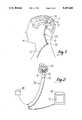
- FIG. 1is a perspective view of a shunt that has been positioned in a patient for relieving fluid pressure on the patient's brain;
- FIG. 2is a perspective view of the novel sheath for shunt placement for hydrocephalus of the present invention, shown being advanced over a shunt into a patient's brain, showing the choroid plexus of the brain;
- FIG. 3is a perspective view of the novel sheath for shunt placement for hydrocephalus of the present invention
- FIG. 4is a cross-sectional view as seen along the line 4--4 in FIG. 3;
- FIG. 5is a perspective view of an alternate embodiment of the novel sheath of the present invention.
- a shunt 10of the type known in the art for relieving hydrocephalus in a patient, has been positioned between the ventricles of a brain 12 of a patient 14, to relieve fluid pressure on the brain 12.
- the shunt 10is essentially a hollow tube that has a closed distal end segment 16 which is formed with a plurality of holes 18.
- the shunt 10has an outer diameter D1 of about three millimeters (3mm) Excess fluid in the cranial cavity flows through the holes 18 into the shunt 10 and through a valve 20, which is positioned in the neck of the patient 14.
- the valve 20can be adjusted prior to implantation in the patient 14 to establish a predetermined flow rate through the valve 0.
- the valve 20is a "Ventricular Shunt Valve" made by PS Medical of Goleta, California.
- a drain tube 22is connected to the valve 20 to establish a passageway for fluid communication from the valve 20 into the chest cavity of the patient 14.
- excess fluid from the cranial cavity of the patient 14can enter the holes 18 of the shunt 10 and drain into the chest cavity of the patient 14 through the drain tube 22 to thereby relieve fluid pressure on the brain of the patient 14.
- the above-described apparatusis effective for relieving the symptoms of hydrocephalus in the patient 14, unless the holes 18 of the shunt 10 become clogged.
- Such an eventcan occur when the distal end segment 16 of the shunt 10 is inadvertently positioned near the choroid plexus 24, which is a portion of the brain 12 of the patient 14 that can grow into the holes 18.
- the holes 18become clogged by ingrown portions of the choroid plexus, as shown in FIG. 2, the effectiveness of the shunt 10 in relieving hydrocephalus is diminished.
- a clogged shunt 10must accordingly be removed from the patient 14 and replaced with another shunt (not shown).
- a clogged shunt 10cannot easily be removed from the patient 14, however, without risking damage to the brain 12 of the patient 14, because the ingrown portions of the choroid plexus tend to tear away portions of the brain 12 when the shunt 10 is retrieved from the brain 12 of the patient 14. Consequently, relatively invasive surgery may be required to gently cut away the ingrown portions of the choroid plexus 24, prior to removing a clogged shunt 10 from a patient 14.
- FIG. 2shows that the present invention recognizes that a clogged shunt 10 can be efficaciously removed from the brain 12 without undue risk of harm to the patient 14, and without requiring relatively invasive surgery.
- a sheathgenerally designated 26, can be advanced over the shunt 10 to cut tissue (e.g., the choroid plexus 24) away from the shunt 10 to facilitate withdrawal of the shunt 10 from the brain 12 of the patient 14, as more fully disclosed below.
- the sheath 26includes a tubular member 28, preferably made of a disposable material, such as plastic, and a cutting element 30.
- the tubular member 28includes a hollow, flexible, thin-walled catheter-like main tube 32 that has an inside diameter ID of between about one and one-half millimeters to about nine millimeters (1.5mm-9mm) and an outer diameter OD which is marginally greater than the inside diameter ID.
- the skilled artisanwill appreciate that the precise dimensions of the tube 32 will be established to provide a close slidable fit with the shunt 10.
- the main tube 32 of the tubular member 28can be slidably engaged with the shunt 10 in a close surrounding relationship therewith. It will be appreciated that placement of the tubular member 28 into the patient 14 only marginally increases the required diameter of the entry site into the patient 14 which must be made incident to placement of the shunt 10 inside the brain 12 of the patient 14.
- the tubular member 28is made of a flexible, axially rigid, biocompatible catheter material, such as wire-reinforced plastic tubing.
- FIG. 3shows that the tubular member 28 also includes a fiber optic tube 34 that is attached to or formed integrally with the main tube 32.
- the fiber optic tube 34has a diameter D2 of about one-quarter to four millimeters (0.25mm-4.0mm).
- the tubular member 28essentially has two lumens--a first one established by the main tube 32, and a second one established by the fiber optic tube 34.
- At least one optical fiber 36is positioned in the fiber optic tube 34 to illuminate the brain 12 of the patient 14 and to conduct back to a video display system 38 (FIG. 2) an image of the brain 12.
- the distal end 40 of the fiber optic tube 34does not extend completely the length of the main tube 32, but instead is positioned proximally relative to the distal end 42 of the main tube 32.
- the cutting element 30is shown to be a hollow, annular, cylindrically-shaped member that is positioned on the distal end segment 44 of the main tube 32. More specifically, the cutting element 30 is positioned in a surrounding stationary relationship with the outer wall of the main tube 32. Preferably, the cutting element 30 is bonded to the main tube 32 by solvent bonding or potting the cutting element 30 to the main tube 32.
- the cutting element 30is made of a biocompatible electrically resistive material, such as a ceramic or a metal (e.g., copper, stainless steel).
- an electrical lead 46is potted in the wall of the main tube 32 and is electrically connected to the cutting element 30.
- the lead 46extends through the main tube 32 and is electrically connected to a source 48 of electricity (FIG. 2).
- the source 48is a Bovie model electrical generator which produces pulses of electricity in response to manipulation of the Bovie by the operator of the sheath 26.
- pulses of electricitycan be applied to the cutting element 30 to selectively heat the element 30 and thereby selectively themally cut or cauterize tissue which is adjacent the cutting element 30.
- FIG. 4shows that the distal edge 50 of the cutting element 30 may be slightly rounded, in order to avoid mechanically damaging tissue of the patient 14 when the sheath 26 is advanced into the brain 12 of the patient 14.
- FIGS. 2 and 3In the operation of the sheath 26, reference is made to FIGS. 2 and 3.
- an entry siteis made in the neck of the patient 14, and the shunt 10 is disconnected from the valve 20.
- the main tube 32 of the sheath 26is engaged with the shunt 10 and is slid distally into the patient 14, over the shunt 10.
- An image of the brain 12is conducted back through the optical fiber 36 to the video display system 38, which presents a display of the brain 12 on an associated monitor 52 by means well-known in the art.
- the surgeoncan determine when the cutting element 30 has been advanced adjacent portions of the choroid plexus 24 that have gron into the holes 18 of the shunt 10.
- the surgeonactivates the source 48 of electricity to heat the cutting element 30 and thereby thermally cut away the ingrown portions from the shunt 10.
- the shunt 10may be withdrawn from the patient 14 through the sheath 26. Then, a new shunt (not shown) is advanced through the sheath 26, and the distal end segment of the new shunt positioned in the brain 12 of the patient 14. When placing the new shunt into the brain 12, the surgeon can view the video monitor 52 to avoid placing the distal end segment near the choroid plexus 24. The sheath 26 is then removed from the patient 14, and the new shunt connected to the valve 20 to reestablish a fluid passageway from the brain 12 to the chest cavity of the patient 14.
- FIG. 5shows a cutting element, generally designated 54, which establishes an electrical dipole (sometimes familiarly referred to as a bipolar cutting element). More particularly, the cutting element 30 has first and second collars 56, 58 which are not connected to each other (i.e., which are closely spaced apart from each other).
- the collars 56, 58conform to a tubular member 60 of a sheath 62.
- the first collar 56has first and second co-parallel straight edges 64, 66, while the second collar 58 has first and second co-parallel straight edges 68, 70.
- the collars 56, 58are positioned on the tubular member 60 with the first edge 64 of the first collar 56 closely spaced from the first edge 68 of the second collar 58. Further, the second edge 66 of the first collar 56 is closely spaced from the second edge 70 of the second collar 58. It can be appreciated in reference to FIG. 5 that the collars 56, 58 have arcuate cross-sections. As the skilled artisan will appreciate, when the cutting element 54 is energized with electricity, most of the thermal cutting energy is located between the edges 64, 66, 68, 70 of the collars 56, 58.
Landscapes
- Health & Medical Sciences (AREA)
- Engineering & Computer Science (AREA)
- Life Sciences & Earth Sciences (AREA)
- Biomedical Technology (AREA)
- Animal Behavior & Ethology (AREA)
- Surgery (AREA)
- Otolaryngology (AREA)
- Heart & Thoracic Surgery (AREA)
- Veterinary Medicine (AREA)
- Public Health (AREA)
- General Health & Medical Sciences (AREA)
- Neurology (AREA)
- Ophthalmology & Optometry (AREA)
- Hematology (AREA)
- Physics & Mathematics (AREA)
- Plasma & Fusion (AREA)
- Nuclear Medicine, Radiotherapy & Molecular Imaging (AREA)
- Anesthesiology (AREA)
- Medical Informatics (AREA)
- Molecular Biology (AREA)
- External Artificial Organs (AREA)
Abstract
Description
Claims (17)
Priority Applications (1)
| Application Number | Priority Date | Filing Date | Title |
|---|---|---|---|
| US07/867,826US5207684A (en) | 1992-04-13 | 1992-04-13 | Sheath for shunt placement for hydrocephalus |
Applications Claiming Priority (1)
| Application Number | Priority Date | Filing Date | Title |
|---|---|---|---|
| US07/867,826US5207684A (en) | 1992-04-13 | 1992-04-13 | Sheath for shunt placement for hydrocephalus |
Publications (1)
| Publication Number | Publication Date |
|---|---|
| US5207684Atrue US5207684A (en) | 1993-05-04 |
Family
ID=25350531
Family Applications (1)
| Application Number | Title | Priority Date | Filing Date |
|---|---|---|---|
| US07/867,826Expired - LifetimeUS5207684A (en) | 1992-04-13 | 1992-04-13 | Sheath for shunt placement for hydrocephalus |
Country Status (1)
| Country | Link |
|---|---|
| US (1) | US5207684A (en) |
Cited By (41)
| Publication number | Priority date | Publication date | Assignee | Title |
|---|---|---|---|---|
| US5402768A (en)* | 1992-09-01 | 1995-04-04 | Adair; Edwin L. | Endoscope with reusable core and disposable sheath with passageways |
| EP0600413A3 (en)* | 1992-11-30 | 1995-04-05 | Neuro Navigational Corp | Neuro endoscope for shunt. |
| US5423806A (en)* | 1993-10-01 | 1995-06-13 | Medtronic, Inc. | Laser extractor for an implanted object |
| US5542936A (en)* | 1995-03-20 | 1996-08-06 | Razi; Dean M. | Sheath for introducing catheter |
| US5700262A (en)* | 1995-10-16 | 1997-12-23 | Neuro Navigational, L.L.C. | Bipolar electrode with fluid channels for less invasive neurosurgery |
| US5814044A (en)* | 1995-02-10 | 1998-09-29 | Enable Medical Corporation | Apparatus and method for morselating and removing tissue from a patient |
| US5817015A (en)* | 1993-06-22 | 1998-10-06 | Adair; Edwin L. | Endoscope with reusable core and disposable sheath with passageways |
| EP0868883A1 (en)* | 1997-04-03 | 1998-10-07 | Elekta Implants S.A. | Catheter for neurosurgery |
| US5928182A (en)* | 1997-07-02 | 1999-07-27 | Johnson & Johnson Professional, Inc. | Pediatric programmable hydrocephalus valve |
| US6126628A (en)* | 1997-04-22 | 2000-10-03 | Johnson & Johnson Professional, Inc. | Fluid flow limiting device |
| US6145505A (en)* | 1995-06-07 | 2000-11-14 | Conceptus, Inc. | Electrically affixed transcervical fallopian tube occlusion devices |
| US6526979B1 (en) | 1995-06-07 | 2003-03-04 | Conceptus, Inc. | Contraceptive transcervical fallopian tube occlusion devices and methods |
| US20030088245A1 (en)* | 2001-11-02 | 2003-05-08 | Arthrocare Corporation | Methods and apparatus for electrosurgical ventriculostomy |
| US20030212395A1 (en)* | 2000-05-12 | 2003-11-13 | Arthrocare Corporation | Systems and methods for electrosurgery |
| US20040024399A1 (en)* | 1995-04-13 | 2004-02-05 | Arthrocare Corporation | Method for repairing damaged intervertebral discs |
| US20040049180A1 (en)* | 1996-07-16 | 2004-03-11 | Arthrocare Corporation | Systems and methods for electrosurgical prevention of disc herniations |
| US6709667B1 (en) | 1999-08-23 | 2004-03-23 | Conceptus, Inc. | Deployment actuation system for intrafallopian contraception |
| US20040087887A1 (en)* | 2000-10-30 | 2004-05-06 | Nilsson Per Erik | System and method for physiological drainage |
| US20040097958A1 (en)* | 2002-07-31 | 2004-05-20 | Whitman Michael P. | Orifice introducer device |
| US6763833B1 (en) | 1999-08-23 | 2004-07-20 | Conceptus, Inc. | Insertion/deployment catheter system for intrafallopian contraception |
| US20050061329A1 (en)* | 2003-09-18 | 2005-03-24 | Conceptus, Inc. | Catheter for intrafallopian contraceptive delivery |
| RU2271228C1 (en)* | 2004-07-27 | 2006-03-10 | Антон Викторович Титов | Liquor bypass system |
| US20070023534A1 (en)* | 2005-07-22 | 2007-02-01 | Mingsheng Liu | Water-source heat pump control system and method |
| RU2295363C1 (en)* | 2005-12-27 | 2007-03-20 | Государственное образовательное учреждение высшего профессионального образования "БАШКИРСКИЙ ГОСУДАРСТВЕННЫЙ МЕДИЦИНСКИЙ УНИВЕРСИТЕТ Федерального Агентства по здравоохранению и социальному развитию" (ГОУ ВПО БГМУ РОСЗДРАВА) | Method for draining lateral ventricles in newborns on intraventricular hemorrhage occasions |
| RU2310399C2 (en)* | 2006-01-10 | 2007-11-20 | Антон Викторович Титов | Method for treating hydrocephalus |
| US7331956B2 (en) | 2000-09-28 | 2008-02-19 | Arthrocare Corporation | Methods and apparatus for treating back pain |
| US7393351B2 (en) | 1995-06-07 | 2008-07-01 | Arthrocare Corporation | Apparatus and methods for treating cervical inter-vertebral discs |
| US7449021B2 (en) | 1996-07-16 | 2008-11-11 | Arthrocare Corporation | Systems and methods for electrosurgical tissue contraction within the spine |
| US7708733B2 (en) | 2003-10-20 | 2010-05-04 | Arthrocare Corporation | Electrosurgical method and apparatus for removing tissue within a bone body |
| US7794456B2 (en) | 2003-05-13 | 2010-09-14 | Arthrocare Corporation | Systems and methods for electrosurgical intervertebral disc replacement |
| US7879034B2 (en) | 2006-03-02 | 2011-02-01 | Arthrocare Corporation | Internally located return electrode electrosurgical apparatus, system and method |
| US7951071B2 (en) | 1999-06-02 | 2011-05-31 | Tyco Healthcare Group Lp | Moisture-detecting shaft for use with an electro-mechanical surgical device |
| US20110166495A1 (en)* | 2008-07-02 | 2011-07-07 | Christoph Miethke | Cerebrospinal fluid drainage |
| US8025199B2 (en) | 2004-02-23 | 2011-09-27 | Tyco Healthcare Group Lp | Surgical cutting and stapling device |
| US8088091B2 (en) | 2009-03-09 | 2012-01-03 | New Jersey Institute Of Technology | No clog shunt using a compact fluid drag path |
| US8357144B2 (en) | 1999-06-02 | 2013-01-22 | Covidien, LP | Electro-mechanical surgical device |
| US8979838B2 (en) | 2010-05-24 | 2015-03-17 | Arthrocare Corporation | Symmetric switching electrode method and related system |
| US9227043B2 (en) | 2011-11-18 | 2016-01-05 | Washington University | Catheter assembly for use with shunt systems and method of using same |
| US10226193B2 (en) | 2015-03-31 | 2019-03-12 | Medtronic Ps Medical, Inc. | Wireless pressure measurement and monitoring for shunts |
| US10232151B2 (en) | 2010-09-29 | 2019-03-19 | Integra Lifesciences Switzerland Sàrl | Multi-lumen ventricular drainage catheter |
| RU2794836C2 (en)* | 2022-05-18 | 2023-04-25 | Антон Николаевич Коновалов | Method of ventriculostomy |
Citations (5)
| Publication number | Priority date | Publication date | Assignee | Title |
|---|---|---|---|---|
| US3020913A (en)* | 1958-07-15 | 1962-02-13 | William T Heyer | Surgical drain |
| US4562838A (en)* | 1981-01-23 | 1986-01-07 | Walker William S | Electrosurgery instrument |
| US4682596A (en)* | 1984-05-22 | 1987-07-28 | Cordis Corporation | Electrosurgical catheter and method for vascular applications |
| US5057107A (en)* | 1989-04-13 | 1991-10-15 | Everest Medical Corporation | Ablation catheter with selectively deployable electrodes |
| US5084045A (en)* | 1990-09-17 | 1992-01-28 | Helenowski Tomasz K | Suction surgical instrument |
- 1992
- 1992-04-13USUS07/867,826patent/US5207684A/ennot_activeExpired - Lifetime
Patent Citations (5)
| Publication number | Priority date | Publication date | Assignee | Title |
|---|---|---|---|---|
| US3020913A (en)* | 1958-07-15 | 1962-02-13 | William T Heyer | Surgical drain |
| US4562838A (en)* | 1981-01-23 | 1986-01-07 | Walker William S | Electrosurgery instrument |
| US4682596A (en)* | 1984-05-22 | 1987-07-28 | Cordis Corporation | Electrosurgical catheter and method for vascular applications |
| US5057107A (en)* | 1989-04-13 | 1991-10-15 | Everest Medical Corporation | Ablation catheter with selectively deployable electrodes |
| US5084045A (en)* | 1990-09-17 | 1992-01-28 | Helenowski Tomasz K | Suction surgical instrument |
Cited By (113)
| Publication number | Priority date | Publication date | Assignee | Title |
|---|---|---|---|---|
| US5402768A (en)* | 1992-09-01 | 1995-04-04 | Adair; Edwin L. | Endoscope with reusable core and disposable sheath with passageways |
| US5458606A (en)* | 1992-11-30 | 1995-10-17 | Neuro Navigational Corporation | Neuro endoscope for shunt |
| EP0600413A3 (en)* | 1992-11-30 | 1995-04-05 | Neuro Navigational Corp | Neuro endoscope for shunt. |
| US5437626A (en)* | 1992-11-30 | 1995-08-01 | Neuro Navigational Corporation | Shunt with internal neuroendoscope |
| US5817015A (en)* | 1993-06-22 | 1998-10-06 | Adair; Edwin L. | Endoscope with reusable core and disposable sheath with passageways |
| US5674217A (en)* | 1993-10-01 | 1997-10-07 | Wahlstrom; Dale A. | Heart synchronized extractor for an implanted object |
| US5423806A (en)* | 1993-10-01 | 1995-06-13 | Medtronic, Inc. | Laser extractor for an implanted object |
| US5814044A (en)* | 1995-02-10 | 1998-09-29 | Enable Medical Corporation | Apparatus and method for morselating and removing tissue from a patient |
| US6007512A (en)* | 1995-02-10 | 1999-12-28 | Enable Medical Corporation | Apparatus and method for morselating and removing tissue from a patient |
| US6036681A (en)* | 1995-02-10 | 2000-03-14 | Enable Medical Corporation | Apparatus and method for morselating and removing tissue from a patient |
| US5957884A (en)* | 1995-02-10 | 1999-09-28 | Enable Medical Corporation | System for morselating and removing tissue from a patient |
| US5542936A (en)* | 1995-03-20 | 1996-08-06 | Razi; Dean M. | Sheath for introducing catheter |
| US7318823B2 (en) | 1995-04-13 | 2008-01-15 | Arthrocare Corporation | Methods for repairing damaged intervertebral discs |
| US20040024399A1 (en)* | 1995-04-13 | 2004-02-05 | Arthrocare Corporation | Method for repairing damaged intervertebral discs |
| US20070062542A1 (en)* | 1995-06-07 | 2007-03-22 | Nikolchev Julian N | Contraceptive transcervical fallopian tube occlusion devices and methods |
| US8356599B2 (en) | 1995-06-07 | 2013-01-22 | Conceptus, Inc. | Occlusion devices and methods |
| US20110030696A1 (en)* | 1995-06-07 | 2011-02-10 | Nikolchev Julian N | Contraceptive transcervical fallopian tube occlusion devices and methods |
| US7921848B2 (en) | 1995-06-07 | 2011-04-12 | Conceptus, Inc. | Contraceptive transcervical fallopian tube occlusion devices and methods |
| US6145505A (en)* | 1995-06-07 | 2000-11-14 | Conceptus, Inc. | Electrically affixed transcervical fallopian tube occlusion devices |
| US6176240B1 (en) | 1995-06-07 | 2001-01-23 | Conceptus, Inc. | Contraceptive transcervical fallopian tube occlusion devices and their delivery |
| US6526979B1 (en) | 1995-06-07 | 2003-03-04 | Conceptus, Inc. | Contraceptive transcervical fallopian tube occlusion devices and methods |
| US7428904B2 (en) | 1995-06-07 | 2008-09-30 | Alien Technology Corporation | Contraceptive transcervical fallopian tube occlusion devices and their delivery |
| US6634361B1 (en) | 1995-06-07 | 2003-10-21 | Conceptus, Inc. | Contraceptive transcervical fallopian tube occlusion devices and methods |
| US7393351B2 (en) | 1995-06-07 | 2008-07-01 | Arthrocare Corporation | Apparatus and methods for treating cervical inter-vertebral discs |
| US6684884B2 (en) | 1995-06-07 | 2004-02-03 | Conceptus, Inc. | Contraceptive transcervical fallopian tube occlusion devices and methods |
| USRE40156E1 (en) | 1995-06-07 | 2008-03-18 | Arthrocare Corporation | Methods for repairing damaged intervertebral discs |
| US8066007B2 (en) | 1995-06-07 | 2011-11-29 | Conceptus, Inc. | Contraceptive transcervical fallopian tube occlusion devices and their delivery |
| US6705323B1 (en) | 1995-06-07 | 2004-03-16 | Conceptus, Inc. | Contraceptive transcervical fallopian tube occlusion devices and methods |
| US8171936B2 (en) | 1995-06-07 | 2012-05-08 | Conceptus, Inc. | Contraceptive transcervical fallopian tube occlusion devices and methods |
| US8327852B2 (en) | 1995-06-07 | 2012-12-11 | Conceptus, Inc. | Occlusion devices and methods |
| US20070144528A1 (en)* | 1995-06-07 | 2007-06-28 | Julian Nikolchev | Contraceptive transcervical fallopian tube occlusion devices and their delivery |
| US20040127918A1 (en)* | 1995-06-07 | 2004-07-01 | Conceptus, Inc. | Contraceptive transcervical fallopian tube occlusion devices and methods |
| US7686020B2 (en) | 1995-06-07 | 2010-03-30 | Conceptus, Inc. | Contraceptive transcervical fallopian tube occlusion devices and methods |
| US20040159324A1 (en)* | 1995-06-07 | 2004-08-19 | Conceptus, Inc. | Contraceptive transcervical fallopian tube occlusion devices and their delivery |
| US20040163651A1 (en)* | 1995-06-07 | 2004-08-26 | Conceptus, Inc. | Transcervical fallopian tube occlusion devices and their delivery |
| US20070044808A1 (en)* | 1995-06-07 | 2007-03-01 | Conceptus, Inc., A California Corporation | Contraceptive transcervical fallopian tube occlusion devices and their delivery |
| US20040206358A1 (en)* | 1995-06-07 | 2004-10-21 | Conceptus, Inc., A California Corporation | Contraceptive transcervical fallopian tube occlusion devices and their delivery |
| US20040211429A1 (en)* | 1995-06-07 | 2004-10-28 | Conceptus, Inc. | Contraceptive transcervical fallopian tube occlusion devices and their delivery |
| US8733361B2 (en) | 1995-06-07 | 2014-05-27 | Bayer Essure Inc. | Occlusion devices and methods |
| US20070000496A1 (en)* | 1995-06-07 | 2007-01-04 | Nikolchev Julian N | Contraceptive transcervical fallopian tube occlusion devices and methods |
| US20060144406A1 (en)* | 1995-06-07 | 2006-07-06 | Nikolchev Julian N | Contraceptive transcervical fallopian tube occlusion devices and methods |
| US5700262A (en)* | 1995-10-16 | 1997-12-23 | Neuro Navigational, L.L.C. | Bipolar electrode with fluid channels for less invasive neurosurgery |
| US20040049180A1 (en)* | 1996-07-16 | 2004-03-11 | Arthrocare Corporation | Systems and methods for electrosurgical prevention of disc herniations |
| US7449021B2 (en) | 1996-07-16 | 2008-11-11 | Arthrocare Corporation | Systems and methods for electrosurgical tissue contraction within the spine |
| US7357798B2 (en) | 1996-07-16 | 2008-04-15 | Arthrocare Corporation | Systems and methods for electrosurgical prevention of disc herniations |
| US6093187A (en)* | 1997-04-03 | 2000-07-25 | Elekta Implants S.A. | Catheter for neurosurgery |
| FR2761589A1 (en)* | 1997-04-03 | 1998-10-09 | Cordis Sa | CATHETER, ESPECIALLY FOR NEUROSURGERY |
| EP0868883A1 (en)* | 1997-04-03 | 1998-10-07 | Elekta Implants S.A. | Catheter for neurosurgery |
| US6126628A (en)* | 1997-04-22 | 2000-10-03 | Johnson & Johnson Professional, Inc. | Fluid flow limiting device |
| US5928182A (en)* | 1997-07-02 | 1999-07-27 | Johnson & Johnson Professional, Inc. | Pediatric programmable hydrocephalus valve |
| US8733360B2 (en) | 1997-09-24 | 2014-05-27 | Bayer Essure Inc. | Occlusion devices and methods |
| US8613282B2 (en) | 1997-09-24 | 2013-12-24 | Conceptus, Inc. | Occlusion devices and methods |
| US9113847B2 (en) | 1999-06-02 | 2015-08-25 | Covidien Lp | Electro-mechanical surgical device |
| US9364200B2 (en) | 1999-06-02 | 2016-06-14 | Covidien Lp | Electro-mechanical surgical device |
| US9247940B2 (en) | 1999-06-02 | 2016-02-02 | Covidien Lp | Surgical cutting and stapling device |
| US10314659B2 (en) | 1999-06-02 | 2019-06-11 | Covidien Lp | Electro-mechanical surgical device |
| US10335143B2 (en) | 1999-06-02 | 2019-07-02 | Covidien Lp | Surgical cutting and stapling device |
| US8628467B2 (en) | 1999-06-02 | 2014-01-14 | Covidien Lp | Moisture-detecting shaft for use with an electro-mechanical surgical device |
| US7951071B2 (en) | 1999-06-02 | 2011-05-31 | Tyco Healthcare Group Lp | Moisture-detecting shaft for use with an electro-mechanical surgical device |
| US8357144B2 (en) | 1999-06-02 | 2013-01-22 | Covidien, LP | Electro-mechanical surgical device |
| US9033868B2 (en) | 1999-06-02 | 2015-05-19 | Covidien Lp | Couplings for interconnecting components of an electro-mechanical surgical device |
| US6709667B1 (en) | 1999-08-23 | 2004-03-23 | Conceptus, Inc. | Deployment actuation system for intrafallopian contraception |
| US20090277463A1 (en)* | 1999-08-23 | 2009-11-12 | Conceptus, Inc., A California Corporation | Deployment Actuation System for Intrafallopian Contraception |
| US7591268B2 (en) | 1999-08-23 | 2009-09-22 | Conceptus, Inc. | Deployment actuation system for intrafallopian contraception |
| US20050232961A1 (en)* | 1999-08-23 | 2005-10-20 | Conceptus, Inc. | Deployment actuation system for intrafallopian contraception |
| US8695604B2 (en) | 1999-08-23 | 2014-04-15 | Bayer Essure Inc. | Deployment actuation system |
| US20040163650A1 (en)* | 1999-08-23 | 2004-08-26 | Conceptus, Inc. | Deployment actuation system for intrafallopian contraception |
| US8584679B2 (en) | 1999-08-23 | 2013-11-19 | Conceptus, Inc. | Deployment actuation system |
| US7506650B2 (en) | 1999-08-23 | 2009-03-24 | Conceptus, Inc. | Deployment actuation system for intrafallopian contraception |
| US8381733B2 (en) | 1999-08-23 | 2013-02-26 | Conceptus, Inc. | Deployment actuation system |
| US6763833B1 (en) | 1999-08-23 | 2004-07-20 | Conceptus, Inc. | Insertion/deployment catheter system for intrafallopian contraception |
| US7934504B2 (en) | 1999-08-23 | 2011-05-03 | Conceptus, Inc. | Deployment actuation system for intrafallopian contraception |
| US7237552B2 (en) | 1999-08-23 | 2007-07-03 | Conceptus, Inc. | Insertion/deployment catheter system for intrafallopian contraception |
| US8079364B2 (en) | 1999-08-23 | 2011-12-20 | Conceptus, Inc. | Deployment actuation system for intrafallopian contraception |
| US9597224B2 (en) | 1999-08-23 | 2017-03-21 | Bayer Healthcare Llc | Deployment actuation system |
| US20030212395A1 (en)* | 2000-05-12 | 2003-11-13 | Arthrocare Corporation | Systems and methods for electrosurgery |
| US7270658B2 (en) | 2000-05-12 | 2007-09-18 | Arthrocare Corporation | Systems and methods for electrosurgery |
| US7462178B2 (en) | 2000-05-12 | 2008-12-09 | Arthrocare Corporation | Systems and methods for electrosurgical spine surgery |
| US7331956B2 (en) | 2000-09-28 | 2008-02-19 | Arthrocare Corporation | Methods and apparatus for treating back pain |
| US20040087887A1 (en)* | 2000-10-30 | 2004-05-06 | Nilsson Per Erik | System and method for physiological drainage |
| US7476211B2 (en) | 2000-10-30 | 2009-01-13 | Technovobis Ab | System and method for physiological drainage |
| US20030088245A1 (en)* | 2001-11-02 | 2003-05-08 | Arthrocare Corporation | Methods and apparatus for electrosurgical ventriculostomy |
| US20040097958A1 (en)* | 2002-07-31 | 2004-05-20 | Whitman Michael P. | Orifice introducer device |
| US9554824B2 (en) | 2002-07-31 | 2017-01-31 | Covidien Lp | Orifice introducer device |
| US7874981B2 (en) | 2002-07-31 | 2011-01-25 | Tyco Healthcare Group Lp | Orifice introducer device |
| US8814785B2 (en) | 2002-07-31 | 2014-08-26 | Covidien Lp | Orifice introducer device |
| US7951141B2 (en) | 2003-05-13 | 2011-05-31 | Arthrocare Corporation | Systems and methods for electrosurgical intervertebral disc replacement |
| US7794456B2 (en) | 2003-05-13 | 2010-09-14 | Arthrocare Corporation | Systems and methods for electrosurgical intervertebral disc replacement |
| US20050061329A1 (en)* | 2003-09-18 | 2005-03-24 | Conceptus, Inc. | Catheter for intrafallopian contraceptive delivery |
| US8801705B2 (en) | 2003-10-20 | 2014-08-12 | Arthrocare Corporation | Electrosurgical method and apparatus for removing tissue within a bone body |
| US7708733B2 (en) | 2003-10-20 | 2010-05-04 | Arthrocare Corporation | Electrosurgical method and apparatus for removing tissue within a bone body |
| US8025199B2 (en) | 2004-02-23 | 2011-09-27 | Tyco Healthcare Group Lp | Surgical cutting and stapling device |
| US11219452B2 (en) | 2004-02-23 | 2022-01-11 | Covidien Lp | Surgical cutting and stapling device |
| RU2271228C1 (en)* | 2004-07-27 | 2006-03-10 | Антон Викторович Титов | Liquor bypass system |
| US20070023534A1 (en)* | 2005-07-22 | 2007-02-01 | Mingsheng Liu | Water-source heat pump control system and method |
| RU2295363C1 (en)* | 2005-12-27 | 2007-03-20 | Государственное образовательное учреждение высшего профессионального образования "БАШКИРСКИЙ ГОСУДАРСТВЕННЫЙ МЕДИЦИНСКИЙ УНИВЕРСИТЕТ Федерального Агентства по здравоохранению и социальному развитию" (ГОУ ВПО БГМУ РОСЗДРАВА) | Method for draining lateral ventricles in newborns on intraventricular hemorrhage occasions |
| RU2310399C2 (en)* | 2006-01-10 | 2007-11-20 | Антон Викторович Титов | Method for treating hydrocephalus |
| US8292887B2 (en) | 2006-03-02 | 2012-10-23 | Arthrocare Corporation | Internally located return electrode electrosurgical apparatus, system and method |
| US7901403B2 (en) | 2006-03-02 | 2011-03-08 | Arthrocare Corporation | Internally located return electrode electrosurgical apparatus, system and method |
| US7879034B2 (en) | 2006-03-02 | 2011-02-01 | Arthrocare Corporation | Internally located return electrode electrosurgical apparatus, system and method |
| US20110166495A1 (en)* | 2008-07-02 | 2011-07-07 | Christoph Miethke | Cerebrospinal fluid drainage |
| US9295821B2 (en) | 2008-07-02 | 2016-03-29 | Christoph Miethke | Cerebrospinal fluid drainage |
| US8088091B2 (en) | 2009-03-09 | 2012-01-03 | New Jersey Institute Of Technology | No clog shunt using a compact fluid drag path |
| US8979838B2 (en) | 2010-05-24 | 2015-03-17 | Arthrocare Corporation | Symmetric switching electrode method and related system |
| US10232151B2 (en) | 2010-09-29 | 2019-03-19 | Integra Lifesciences Switzerland Sàrl | Multi-lumen ventricular drainage catheter |
| US9227043B2 (en) | 2011-11-18 | 2016-01-05 | Washington University | Catheter assembly for use with shunt systems and method of using same |
| US10773060B2 (en) | 2011-11-18 | 2020-09-15 | Washington University | Method of using a catheter assembly |
| US11944768B2 (en) | 2011-11-18 | 2024-04-02 | Washington University | Catheter tip for a catheter assembly |
| US10226193B2 (en) | 2015-03-31 | 2019-03-12 | Medtronic Ps Medical, Inc. | Wireless pressure measurement and monitoring for shunts |
| US11375915B2 (en) | 2015-03-31 | 2022-07-05 | Medtronic Navigation, Inc. | Wireless pressure measurement and monitoring for shunts |
| US11844597B2 (en) | 2015-03-31 | 2023-12-19 | Medtronic Navigation, Inc. | Wireless pressure measurement and monitoring for shunts |
| US12295709B2 (en) | 2015-03-31 | 2025-05-13 | Medtronic Navigation, Inc. | Wireless pressure measurement and monitoring for shunts |
| RU2794836C2 (en)* | 2022-05-18 | 2023-04-25 | Антон Николаевич Коновалов | Method of ventriculostomy |
Similar Documents
| Publication | Publication Date | Title |
|---|---|---|
| US5207684A (en) | Sheath for shunt placement for hydrocephalus | |
| US5437626A (en) | Shunt with internal neuroendoscope | |
| US7226441B2 (en) | Catheter with block-overriding system | |
| US7044980B2 (en) | Facilitating drainage | |
| US4790311A (en) | Radio frequency angioplasty catheter system | |
| US6156035A (en) | Electrocautery method and apparatus | |
| JP4303116B2 (en) | Ophthalmic microsurgery device | |
| EP0316796B1 (en) | Intravascular ultrasonic catheter probe for treating intravascular blockage | |
| JP4989633B2 (en) | Biomechanical probe | |
| US4341212A (en) | Serous fluid drain kit | |
| US4632668A (en) | Ventricular catheter | |
| US20060122582A1 (en) | Device and method for dacryocystorhinostomy | |
| JP2000300679A (en) | Catheter system | |
| JP2010533565A (en) | Intraocular implant with hydrogel expansion capability | |
| EP3463115B1 (en) | Minimally invasive device for endourologic treatment | |
| CN101360523A (en) | Glaucoma Treatment Device | |
| Powers | Fenestration of intraventricular cysts using a flexible, steerable endoscope and the argon laser | |
| US5766195A (en) | Optical shunt cutter system | |
| US20090124927A1 (en) | Endoscopic system for lung biopsy and biopsy method of insufflating gas to collapse a lung | |
| JP3233953B2 (en) | Catheter device | |
| WO2013123304A1 (en) | Stone retrieval device | |
| WO2003007861A1 (en) | System for performing a micro-drilling procedure in human or animal and a method for use thereof | |
| JP2011010834A (en) | Catheter and medicine supply/body fluid suction system using the same | |
| ES2229748T3 (en) | DEVICE FOR THE EXTENSION AND RESTORATION OF LACRIMAL DUCT IN THE HUMAN EYE. | |
| US11547475B2 (en) | System for its use in the treatment of vascular stenosis and occlusions |
Legal Events
| Date | Code | Title | Description |
|---|---|---|---|
| AS | Assignment | Owner name:NEURO NAVIGATIONAL CORP. A CA CORP., CALIFORNIA Free format text:ASSIGNMENT OF ASSIGNORS INTEREST.;ASSIGNOR:NOBLES, ANTHONY A.;REEL/FRAME:006146/0695 Effective date:19920511 | |
| STCF | Information on status: patent grant | Free format text:PATENTED CASE | |
| FPAY | Fee payment | Year of fee payment:4 | |
| AS | Assignment | Owner name:BALLARD MEDICAL PRODUCTS, UTAH Free format text:SECURITY AGREEMENT;ASSIGNOR:NEURO NAVIGATIONAL CORPORATION ENDOVASCULAR, INC.;REEL/FRAME:008048/0686 Effective date:19960301 | |
| AS | Assignment | Owner name:NEURO NAVIGATIONAL, L.L.C., CALIFORNIA Free format text:ASSIGNMENT OF ASSIGNORS INTEREST;ASSIGNOR:BALLARD PURCHASE CORPORATION;REEL/FRAME:008650/0438 Effective date:19970320 Owner name:BALLARD PURCHASE CORPORATION, UTAH Free format text:ASSIGNMENT OF ASSIGNORS INTEREST;ASSIGNOR:NEURO NAVIGATIONAL CORPORATION;REEL/FRAME:008650/0434 Effective date:19970320 | |
| AS | Assignment | Owner name:FLEET CAPITAL CORPORATION, ILLINOIS Free format text:SECURITY INTEREST;ASSIGNOR:NEURO NAVIGATIONAL, L.L.C.;REEL/FRAME:008886/0629 Effective date:19980108 | |
| FEPP | Fee payment procedure | Free format text:PAT HLDR NO LONGER CLAIMS SMALL ENT STAT AS SMALL BUSINESS (ORIGINAL EVENT CODE: LSM2); ENTITY STATUS OF PATENT OWNER: LARGE ENTITY | |
| REMI | Maintenance fee reminder mailed | ||
| FPAY | Fee payment | Year of fee payment:8 | |
| SULP | Surcharge for late payment | Year of fee payment:7 | |
| FPAY | Fee payment | Year of fee payment:12 |