US5207676A - External fixator with controllable damping - Google Patents
External fixator with controllable dampingDownload PDFInfo
- Publication number
- US5207676A US5207676AUS07/689,654US68965491AUS5207676AUS 5207676 AUS5207676 AUS 5207676AUS 68965491 AUS68965491 AUS 68965491AUS 5207676 AUS5207676 AUS 5207676A
- Authority
- US
- United States
- Prior art keywords
- bar
- casing
- external fixator
- support
- fixator according
- Prior art date
- Legal status (The legal status is an assumption and is not a legal conclusion. Google has not performed a legal analysis and makes no representation as to the accuracy of the status listed.)
- Expired - Lifetime
Links
- 238000013016dampingMethods0.000titleclaimsabstractdescription24
- 210000000988bone and boneAnatomy0.000claimsabstractdescription52
- 238000006073displacement reactionMethods0.000claimsabstractdescription49
- 239000012634fragmentSubstances0.000claimsabstractdescription18
- 230000000694effectsEffects0.000claimsdescription8
- 230000009471actionEffects0.000claimsdescription2
- 230000000638stimulationEffects0.000claimsdescription2
- 230000009467reductionEffects0.000abstractdescription3
- 230000001105regulatory effectEffects0.000abstract1
- 230000006835compressionEffects0.000description13
- 238000007906compressionMethods0.000description13
- 206010020649HyperkeratosisDiseases0.000description6
- 238000000034methodMethods0.000description4
- 230000000399orthopedic effectEffects0.000description3
- 230000015572biosynthetic processEffects0.000description2
- 238000010276constructionMethods0.000description2
- 230000036244malformationEffects0.000description2
- 210000003205muscleAnatomy0.000description2
- 230000008569processEffects0.000description2
- OKTJSMMVPCPJKN-UHFFFAOYSA-NCarbonChemical compound[C]OKTJSMMVPCPJKN-UHFFFAOYSA-N0.000description1
- 206010010356Congenital anomalyDiseases0.000description1
- 238000004026adhesive bondingMethods0.000description1
- XAGFODPZIPBFFR-UHFFFAOYSA-NaluminiumChemical compound[Al]XAGFODPZIPBFFR-UHFFFAOYSA-N0.000description1
- 229910052782aluminiumInorganic materials0.000description1
- 239000004411aluminiumSubstances0.000description1
- 230000008901benefitEffects0.000description1
- 229910052799carbonInorganic materials0.000description1
- 238000006243chemical reactionMethods0.000description1
- 210000003275diaphysisAnatomy0.000description1
- 210000002745epiphysisAnatomy0.000description1
- 229910001234light alloyInorganic materials0.000description1
- 230000014759maintenance of locationEffects0.000description1
- 238000005259measurementMethods0.000description1
- 238000005096rolling processMethods0.000description1
- 238000005476solderingMethods0.000description1
- 239000010935stainless steelSubstances0.000description1
- 229910001220stainless steelInorganic materials0.000description1
- 238000001356surgical procedureMethods0.000description1
- 210000001519tissueAnatomy0.000description1
- 230000036642wellbeingEffects0.000description1
Images
Classifications
- A—HUMAN NECESSITIES
- A61—MEDICAL OR VETERINARY SCIENCE; HYGIENE
- A61B—DIAGNOSIS; SURGERY; IDENTIFICATION
- A61B17/00—Surgical instruments, devices or methods
- A61B17/56—Surgical instruments or methods for treatment of bones or joints; Devices specially adapted therefor
- A61B17/58—Surgical instruments or methods for treatment of bones or joints; Devices specially adapted therefor for osteosynthesis, e.g. bone plates, screws or setting implements
- A61B17/60—Surgical instruments or methods for treatment of bones or joints; Devices specially adapted therefor for osteosynthesis, e.g. bone plates, screws or setting implements for external osteosynthesis, e.g. distractors, contractors
- A61B17/64—Devices extending alongside the bones to be positioned
- A61B17/6491—Devices extending alongside the bones to be positioned allowing small-scale motion of bone ends
- A—HUMAN NECESSITIES
- A61—MEDICAL OR VETERINARY SCIENCE; HYGIENE
- A61B—DIAGNOSIS; SURGERY; IDENTIFICATION
- A61B17/00—Surgical instruments, devices or methods
- A61B17/56—Surgical instruments or methods for treatment of bones or joints; Devices specially adapted therefor
- A61B17/58—Surgical instruments or methods for treatment of bones or joints; Devices specially adapted therefor for osteosynthesis, e.g. bone plates, screws or setting implements
- A61B17/60—Surgical instruments or methods for treatment of bones or joints; Devices specially adapted therefor for osteosynthesis, e.g. bone plates, screws or setting implements for external osteosynthesis, e.g. distractors, contractors
- A61B17/66—Alignment, compression or distraction mechanisms
- A—HUMAN NECESSITIES
- A61—MEDICAL OR VETERINARY SCIENCE; HYGIENE
- A61B—DIAGNOSIS; SURGERY; IDENTIFICATION
- A61B17/00—Surgical instruments, devices or methods
- A61B17/56—Surgical instruments or methods for treatment of bones or joints; Devices specially adapted therefor
- A61B17/58—Surgical instruments or methods for treatment of bones or joints; Devices specially adapted therefor for osteosynthesis, e.g. bone plates, screws or setting implements
- A61B17/60—Surgical instruments or methods for treatment of bones or joints; Devices specially adapted therefor for osteosynthesis, e.g. bone plates, screws or setting implements for external osteosynthesis, e.g. distractors, contractors
- A61B2017/606—Surgical instruments or methods for treatment of bones or joints; Devices specially adapted therefor for osteosynthesis, e.g. bone plates, screws or setting implements for external osteosynthesis, e.g. distractors, contractors with resilient spring element
Definitions
- the present inventionrelates to the field of traumatology and orthopedics and more particularly has as its object an external bone fixation device utilizing pins inserted into the bone.
- the inventionrelates to external fixators connected to sets of pins inserted into the bone and permitting longitudinal displacement of the sets of pins relative to the bone, while retaining their angular positions.
- the bonemay also be one intentionally cut through, for example for the purpose of orthopedic elongation. It may also be a bone which is not fractured or cut through, but the length of which it is desired to vary by compression or elongation, as is done in the case of young patients.
- the pinsare connected to an external fixation bar disposed substantially parallel to the fractured bone.
- Each set of pins inserted into a bone fragmentis gripped in a support which can be oriented in relation to the fixation bar and which is fastened to a clip fixing it on the bar.
- a supportwhich can be oriented in relation to the fixation bar and which is fastened to a clip fixing it on the bar.
- an external fixatorwhich has two sets of pins inserted into the bone and fixed to fastening clips, one of the pin fastening clips being movable along a fixation bar disposed parallel to the bone.
- An elastic memberis provided in the part connecting the two clips and effects compression of the fracture over a limited path.
- this fixatorcan be equipped with pneumatic or mechanical means enabling passive stimulation to be achieved.
- the longitudinal displacementis achieved through a telescopic movement between two polygonal tubes, of which one is fastened to a worm and the other to a nut.
- a sliding guide memberis interposed between these two telescopic members to prevent any play and to allow frictionless sliding of one of the members relative to the other.
- the present inventionseeks to achieve control of the force applied on the relative displacement of the two sets of pins inserted into the bone fragments, in the case of either compression or elongation, in order to avoid damaging the callus being formed when the displacement force is applied.
- the subject of the inventionis an external fixator for the correction and reduction of bone fragments, which comprises a rigid bar disposed substantially parallel to the bone, at least two supports for the orientation of the pins inserted into the bone fragments, the distance between said supports being adjustable with the aid of a displacement member preventing any rotation between the supports, while the bar is provided with a member damping the longitudinal displacement.
- the first supportis fastened to a casing which is disposed at an end of the rigid bar and adapted to move relative to a sliding block fixed to the end of the bar, in such a manner as to obtain a reciprocating movement of the casing relative to the bar and to avoid any angular displacement;
- the second supportis displaceable longitudinally relative to the first one with the aid of said displacement member
- the damping membercooperates with damping force adjustment means disposed outside the end of the fixator.
- the sliding blockhas shapes intended to cooperate with corresponding cutouts in a connection member, in such a manner as to avoid any angular displacement.
- This sliding blockhas an end having a polygonal section and intended to slide, relative to the casing, in a needle bearing. Provision is advantageously made for the permitted length of longitudinal reciprocating movement to be limited in a predetermined manner.
- the pin orientation supportsconsist of jaws disposed one on each side of the bar and cooperating with a curved deflection member adapted to permit the angular pivoting of clamps gripping the bone pins.
- an angle drivemay be inserted between the curved deflection member and the clamp.
- the damping memberconsists of an elastic member compressed between two bearing surfaces, for example a coil spring, and means are provided for varying its compression.
- a rod adapted to project outside the baris provided with graduated markings suitable for indicating values of forces.
- a tubular bar of which one outer face carries graduations permitting measurement of the displacement made with the aid of the displacement memberIn a preferred embodiment the bar has a generally quadrangular shape with edges cut off at 20° in order to effect the positioning of the pin orientation supports.
- the displacement member adapted to effect the displacement of one of the supportsconsists of a displacement assembly disposed outside the bar and provided with means for fastening it to the bar and with means for the longitudinal displacement of said support.
- the displacement member adapted to effect the displacement of one of the supportsconsists of a device inside a bar consisting of telescopic tubes.
- This devicemay include a bevel gear unit in which one of the shafts can be driven from the outside, while the other shaft is fastened to a threaded rod adapted to cooperate with the telescopic tube which is to be displaced.
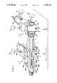
- FIG. 1is a schematic view in perspective of a first form of construction of an external fixator provided in addition with a device for the longitudinal displacement, along a fixation bar, of one of the clips fastening the pins inserted into a bone fragment.
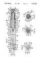
- FIG. 2is a longitudinal section of the fixation bar and of the biocompression system which are shown in FIG. 1, taken on the lines II--II shown in FIGS. 4 and 5.
- FIG. 3is an end view of the free end of the fixation bar shown in FIG. 2.
- FIG. 4is a cross-section of the connection end of the fixation bar, taken on the line IV--IV in FIG. 2.
- FIG. 5is a cross-section of the biocompression system, taken on the line V--V in FIG. 2.
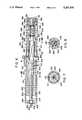
- FIG. 6shows in longitudinal section a variant form of construction of a fixation bar comprising telescopic members.
- FIG. 7is a cross-section on the line VII--VII of the fixation bar shown in FIG. 6.
- FIG. 8is a cross-section on the line VIII--VIII of the fixation bar shown in FIG. 6.
- FIG. 1shows an external fixation bar 1 of polygonal section, on which are placed two clips 2 and 3 fastened indirectly to clamps 21 and 31 holding pins 25 and 35.
- Each clip 2 or 3is provided with a curved deflection member 22, 32 cooperating with a pair of jaws 23, 33 disposed one on each side of the bar 1, on which they are fixed by a positioning device 24, 34.
- the curved deflection member 22permits the angular pivoting of the clamp 21 in the direction of the arrow A, on the one hand, and the continuous orientation from 0° to 360° of the set of pins 25 relative to the clamping axis 26, in the direction of the arrow B, on the other hand.
- the clip 3is in addition provided with an angle drive means 37 enabling the clamp 31, and consequently the pins 35, to be turned 90°.
- An angle drive of this kindis for example used when the pins 35 are intended to be inserted into the epiphysis (for example the tibial or femoral head) of a bone whose diaphysis would receive the pins 25.
- the clip 3In addition to the circular pivoting in the direction of the arrow A and the angular orientation in the direction of the arrow B, the clip 3 also permits angular orientation in accordance with the arrow C in relation to the axis 36 on which the pins 35 are clamped.
- the arrow Erepresents the displacement of the clip along the bar, effecting the elongation or compression of the bone parallel to the bar, while the arrow F represents the limited biocompression movement, which is adjustable with the aid of the knurled nut 4 displaceable between the end of the bar 1 and the biocompression system 5, as will be seen in detail later on.
- the biocompression system 5is of generally cylindrical shape, thus also permitting the angular positioning of the clip 3 in the direction of the arrow D with the aid of an intermediate connection member 38, whose external shapes correspond to the internal cutouts of the jaws 33.
- the connection member 38is also provided with an external collar 39 on each side of the clip 3, the purpose of which is to hold the connection member 38 in the clip.
- FIG. 1also shows a member 6 for the displacement of the clip 2 along the bar 1, which may be provided with linear markings 11, usually graduated in millimeters.
- the displacement member 6consists of a fastening clip 601 composed of two parts articulated on an axis 602, and is clamped on the bar 1 by a screw 603. It also comprises a support 604 fixed for rotation with the clip 601 and having an opening for the retention of the head 605 of a feed screw 606, along which is moved a threaded boss 607 integral with a clamp 608 provided with two flanges 609 intended to embrace the side portion of the jaw 23 of the clip 2.
- the external fixation bar 1can be seen again under the reference 100.
- ithas a polygonal section, which is visible in the end view shown in FIG. 3, where it will be noted that the bar 100 has parallel faces 101 and 102, each followed by faces 103 and 104 inclined at 20° in such a manner as to provide optimum clamping of the bar in internal cutouts of corresponding shapes in the jaws of the clip.
- a fixation bar of circular cross-sectioncan be used, on which are clamped clips of corresponding shape.
- the fixation bar 100is tubular and has a circular central opening 105 terminating at each end of the bar in an internal screwthread 106 and 107 respectively.
- the internal screwthread 106receives a connection member 110 which is of generally cylindrical shape and has a median collar 111 serving as a stop on the one hand for the screwthread 112 making the connection to the fixation bar, or more precisely with the internal screwthread 106 of said bar, and on the other hand for the screwthread 113 intended to receive the knurled nut 4 previously mentioned.
- connection member 110is provided with a circular central opening 114 ending externally in a recess 115 having at least one plane face 116 (more readily visible in FIG. 4), which is intended to prevent any rotation of the shaft passing through the opening 114.
- the recess 115forms a stop shoulder 117 for said shaft which will be described in detail later on.
- the internal screwthread 107receives an adjusting end piece 120 of generally cylindrical shape, which has an external screwthread 121 matching the internal screwthread 107.
- the free end of the end piece 120is provided with grip means, consisting for example of a hexagon 122 integral with the end piece 120 and following a frustoconical narrowed portion 123.
- the adjusting end piece 120has a circular central opening 124, in which a rod, the purpose of which will be mentioned later on, is slidable.
- the central opening 124leads into a recess 125 forming a stop shoulder 126.
- the biocompression system 5 previously mentioned in connection with FIG. 1is shown in detail in longitudinal section and cross-section respectively in FIGS. 2 and 5.
- the casing 50is composed of a casing 50 of generally cylindrical shape and provided at one end with an external collar 51 equipped with an internal screwthread, while the other end is closed by a wall 52 provided with a central passage 53 and an external recess 54.
- the casing 50has a central opening 55 leading into four inclined cutouts 56 intended to receive four shims 57 each having a curvature corresponding to the cutouts 56 and also a longitudinally inclined plane face.
- the cutouts 56are formed in such a manner that the plane faces of the shims 57 constitute the sliding faces of a needle bearing 60 provided with a cage 61 having a generally cylindrical shape and four external plane faces 62, along which are formed ladderlike cutouts 63 intended to receive the needles 64 constituting the needle bearing 60 (see FIG. 5).
- the shims 57 and the needle cage 60are held in the central opening 55 of the casing 50 by means of a washer 58 having an external screwthread intended to cooperate with the internal screwthread formed in the collar 51.
- the washer 58is provided with cutouts 59 intended to receive a tightening tool of suitable shape.
- a sliding block 70constituted by a tubular shaft having in succession:
- a median collar 74forming a stop shoulder 75 intended to cooperate with the stop shoulder 117 of the connecting member 110, the external contour of which collar is provided with flats 76 intended to engage against the plane faces 116 of the connecting member 110;
- the tubular shaft 70has a central passage 78 of circular section, which is intended for the passage of a central shaft 80.
- the central shaft 80has at one end a collar 81 intended to bear against the inside of the wall 52, and its end 82 engages in the opening 53 in the casing 50, in which it is fixed by means of a screw 83 engaging in a central internally threaded opening 84 in the central shaft 80.
- a washer 85In order to fasten the central shaft 80 in the casing 50 it is advantageous to dispose a washer 85 at the bottom of the external recess 54, thus in addition enabling the head of the screw 83 to be partly recessed.
- the opposite end of the central shaft 80 to that where the biocompression system is disposedis provided with means for retaining the whole arrangement, consisting here of a nut 86 engaged on a terminal threaded portion 87 of the central shaft 80.
- the nut 86is dimensioned to bear against the end 71 of circular section of the tubular shaft 70.
- the threaded portion 87enables the connection to be made between the central shaft 80 and a means 90 the damping action of which is adjustable.
- This damping means 90consists of a rod 91 provided at one end with a central internally threaded opening 92 intended to cooperate with the threaded portion 87 of the central shaft.
- the damping means 90is provided with tightening means consisting, for example, of a hexagonal portion 93.
- Said rodis also provided with a median collar 94, against which bears the end 95 of a coil spring 96, whose other end 97 is received in the recess 125 and bears against the stop shoulder 126.
- the means 90ends in a rod 98 intended to slide in the central circular opening 124 in the adjusting end piece 120.
- the end of the rod 98is provided with markings 99 the purpose of which will be mentioned later on.
- the fixation baris telescopic in order to permit the displacement, relative to one another, of the clips fastening the pins. Furthermore the damping means is disposed at the end of the casing.
- the biocompressions systemis found again composed of a casing 250 which receives in four inclined cutouts 256 shims 257 cooperating with the needles 264 of the bearing 260 intended to facilitate the reciprocating movement of the sliding block 270.
- the needle bearing 260is disposed between the washer 258 threaded in the external collar 251 and an intermediate wall 253, while the damping member is located in the extension 252 of the casing, between said intermediate wall 253 and a plug 280 fixed in an internal screwthread 254 realized at the end of the tubular extension 252 of the casing.
- the sliding block 270presents:
- the sliding block 270may have a central opening 278 (FIG. 8) in which a shaft 279, the use of which will be mentioned later on, is slidable.
- the plug 280is provided with external cutouts 281 intended to receive a tightening tool for its fixation in the internal screwthread 254 realized at the end of the tube 253.
- the plugpresents a central recess 282 having circular groves 283 intended to control the position of the damping member 290 (and consequently to measure the force applied), as well as an screwthreaded end wall 284 intended to receive the adjusting end-piece 291 for adjusting the force applied.
- the damping means 290is constituted by an external screwthreaded end-piece 291, having on its external face grip means, not represented in the drawing.
- the internal face of the end-piece 291presents an internal screwthread intended to receive a screw 292 bearing on a washer 294.
- a spring 296is situated between the washers 276 and 294, and its force can be adjusted by positioning the end-piece 291 in the plug 280.
- the fixation rod 200is constituted by an inner tube 210 and an outer tube 220, of circular cross-section.
- a graduated scalemakes it possible to measure the relative displacement of the tubes.
- the tubes 210 and 220are of aluminium.
- the inner tubepresents a fluting 211 in which slides a toe 221 of the outer tube.
- the relative movement of the tubesis obtained by means of a threaded shaft 201, maintained in a central hollow 222 of the outer tube wall 223 by means of two circlips 202 disposed in circular groves on each side of the wall 223.
- the already mentioned shaft 279passes through the threaded shaft 201 and protrudes at its free end.
- the shaft 201has grip means constituted by a squared end 203 or any other equivalent means.
- the threaded portion of the shaft 201cooperates with a internal screwthread in the lateral wall 212.
- the inner tube 210is provided at the end receiving the biocompression system with an external screwthread 213 intended to cooperate with the previously mentioned knurled nut 4.
- the various external components constituting the fixator according to the inventionhave no sharp edges and for the most part are made of light alloys in order to limit the weight of the apparatus.
- the fixator according to the inventionis assembled in the manner illustrated in the drawing.
- the biocompression casing 50is assembled by inserting the shims 57 into the corresponding inclined cutouts 56, and then inserting the needle cage 60 surrounding the end 77 of quadrangular section of the sliding block 70, in the centre of which the central shaft 80 is disposed.
- the collar 81 disposed at the end of said shaftis pressed against the wall 52 by means of the screw 83 and the washer 85, in such a manner as to secure the central shaft 80.
- This biocompression system thus formedis mounted at the end of an external fixation bar and its movement is facilitated by the rolling system in the needle cage 60.
- the retaining nut 73is tightened on the screwthread 72 in such a manner as to fasten the biocompression system to the external fixation bar, or more precisely to the connection member 110.
- the corresponding flats 116 and 76 of the connection member 110 and of the median collar 74prevent any rotation between the fixation bar and the biocompression casing.
- the stop nut 86is disposed on the threaded end portion 87 of the central shaft 80, in such a manner as to prevent the withdrawal of the biocompression system in the outward direction.
- the internally threaded central opening 92 at the end of the rod 91is screwed onto the threaded portion 87 with the aid of a tool matching the hexagonal portion 93.
- the coil spring 96is placed in position on the rod 91, between the median collar 94 and the stop shoulder 126 on the adjusting end piece 120.
- each set of pins 25 or 35is held in a plane by means of the clamp 21 or 31 and is positioned relative to the bar 1 by taking advantage of the possible orientations in the directions of the arrows A, B, C and D (FIG. 1), which make it possible to dispose the bar parallel to the bone which is to be compressed or elongated. It is obvious that the angle drive device 37 is dispensed with in certain cases.
- the clip 2is disposed on the bar 1 with the aid of the positioning device 24 in such a manner as to be able to be displaced laterally by the displacement member 6, whose fastening clip 601 is clamped on the bar 1 with the aid of the screw 603.
- the clip 3is fastened to the biocompression system 5 through the tightening of the jaws 33 with the aid of the positioning device 34. It will be observed that by constructional measures it is easily possible to modify the relative angle between the two clips, since the clip 3 is mounted on a circular member, namely the biocompression casing 50, in order to allow adjustment in the direction of the arrow D in FIG. 1.
- the biocompression force by acting on the end piece 120which enables the spring 96 to be compressed to a greater or lesser extent, the markings 99 on the rod 98 which slides in the central opening 124 in the end piece enabling this force to be measured.
- the markingscorrespond to values expressed in kilogram force.
- a displacement of the clip 2 by 1 millimetercorresponds to a displacement by 1 millimeter of the bone when equilibrium exists between the force of the spring 96 and the resistance of the patient's limb to elongation or compression.
- the damping means 90through its spring 96, makes it possible to prevent the tearing of the callus being formed (anticollapse) at the moment when the clip 2 is displaced.
- a displacement of the order of 1 millimeter a dayis made, but this value may vary in dependance on the age of the patient and other individual criteria, such as the rate of formation of the callus.
- feed screw 606may be turned by automatic means, such as a drive motor, without departing from the scope of the present invention.
- the casing 250is tightened at the end of the inner tube 210, by means of the collar 273.
- the biocompression forceis adjusted by means of the end-piece 291 and is measured on the marks 283 visible in the recess 282 beyond the end-piece 291.
- the two telescopic tubes 210 and 220are then joined together by inserting the threaded shaft 201.
- the biocompression movementscan be mechanically or electrically driven, in cases where the patient is confined to his bed.
- the motor drive unitmay consist of an electric motor turning an eccentric fastened to the free end of the shaft 279, which it drives in a reciprocating movement against the spring 296.
- the telescopic fixation bar shown in FIGS. 6 to 8is placed in position in the course of the operation, as indicated previously, and the fastening clips are clamped around the biocompression casing 250, on the one hand, and around the outer tube 220 of the telescopic tube 200, on the other hand.
- biocompression displacementsare independent of the elongation or compression.
- amplitude of the biocompression movementsis adjustable with the aid of the knurled nut 4.
- any movement of one of the telescopic tubes relative to the otherhas the effect on the bone of a displacement different from that indicated on the graduated scale on the inner tube 210. It is in fact first necessary to balance the compression of the spring with the resistance reactions of the muscles and tissues, and only then will a relative displacement of the telescopic tubes by 1 millimeter result in an equivalent displacement of the sets of pins inserted into the bone.
- the fixator according to the inventioncan be used to displace a bone segment between two parts of a long bone.
- the fixatorcomprises two fixed supports and a displaceable support which is fastened to the bone fragment. It is further possible tu use some of the described components in a fixator maintaining the pins, without any compression or elongation of the bone.
- fixation barwith ball joint type pin supports enabling the pins to be positioned in the desired plane and fastened on the one hand to the fixation bar and on the other hand to the biocompression casing.
Landscapes
- Health & Medical Sciences (AREA)
- Orthopedic Medicine & Surgery (AREA)
- Life Sciences & Earth Sciences (AREA)
- Surgery (AREA)
- Biomedical Technology (AREA)
- Engineering & Computer Science (AREA)
- Nuclear Medicine, Radiotherapy & Molecular Imaging (AREA)
- Heart & Thoracic Surgery (AREA)
- Medical Informatics (AREA)
- Molecular Biology (AREA)
- Animal Behavior & Ethology (AREA)
- General Health & Medical Sciences (AREA)
- Public Health (AREA)
- Veterinary Medicine (AREA)
- Surgical Instruments (AREA)
Abstract
Description
Claims (25)
Priority Applications (1)
| Application Number | Priority Date | Filing Date | Title |
|---|---|---|---|
| US07/689,654US5207676A (en) | 1989-02-27 | 1991-04-23 | External fixator with controllable damping |
Applications Claiming Priority (4)
| Application Number | Priority Date | Filing Date | Title |
|---|---|---|---|
| CH698/89-3 | 1989-02-27 | ||
| CH698/89ACH679448A5 (en) | 1989-02-27 | 1989-02-27 | |
| US48509590A | 1990-02-26 | 1990-02-26 | |
| US07/689,654US5207676A (en) | 1989-02-27 | 1991-04-23 | External fixator with controllable damping |
Related Parent Applications (1)
| Application Number | Title | Priority Date | Filing Date |
|---|---|---|---|
| US48509590AContinuation | 1989-02-27 | 1990-02-26 |
Publications (1)
| Publication Number | Publication Date |
|---|---|
| US5207676Atrue US5207676A (en) | 1993-05-04 |
Family
ID=27172330
Family Applications (1)
| Application Number | Title | Priority Date | Filing Date |
|---|---|---|---|
| US07/689,654Expired - LifetimeUS5207676A (en) | 1989-02-27 | 1991-04-23 | External fixator with controllable damping |
Country Status (1)
| Country | Link |
|---|---|
| US (1) | US5207676A (en) |
Cited By (133)
| Publication number | Priority date | Publication date | Assignee | Title |
|---|---|---|---|---|
| US5320623A (en)* | 1991-07-16 | 1994-06-14 | Orthofix S.R.1. | Clamping coupling for an external fixator |
| US5391167A (en)* | 1992-09-01 | 1995-02-21 | Ortho-Motion, Inc. | Articulating external fixation device |
| US5454810A (en)* | 1990-02-05 | 1995-10-03 | Pohl; Anthony P. | External fixation device |
| US5662650A (en)* | 1995-05-12 | 1997-09-02 | Electro-Biology, Inc. | Method and apparatus for external fixation of large bones |
| US5683389A (en)* | 1994-12-05 | 1997-11-04 | Smith & Nephew, Inc. | External fixator for distal radius fractures |
| US5725526A (en)* | 1995-11-27 | 1998-03-10 | Zimmer, Inc. | Transport carriage for an external fixator |
| US5728096A (en)* | 1994-08-23 | 1998-03-17 | Orthofix S.R.L. | External trochanter splint |
| US5733291A (en)* | 1996-10-10 | 1998-03-31 | Hayes Medical, Incorporated | Long bone alignment tool |
| US5743898A (en)* | 1995-05-12 | 1998-04-28 | Electro-Biology, Inc. | Method and apparatus for external fixation of small bones |
| US5746741A (en)* | 1996-05-06 | 1998-05-05 | Tufts University | External fixator system |
| US5769820A (en)* | 1993-10-22 | 1998-06-23 | David H. Rammler | Abdominal lifting apparatus and methods for trocar surgical procedure |
| US5797911A (en)* | 1996-09-24 | 1998-08-25 | Sdgi Holdings, Inc. | Multi-axial bone screw assembly |
| US5797908A (en)* | 1997-02-04 | 1998-08-25 | Bristol-Myers Squibb Company | External fixator assembly and clamp therefor |
| US5827283A (en)* | 1996-03-21 | 1998-10-27 | Groiso; Jorge Abel | Device and method for locating two bones into a desired relative position |
| US5843081A (en)* | 1993-12-14 | 1998-12-01 | Richardson; James Bruce | Patient-operated orthopedic device |
| US5873843A (en)* | 1994-02-18 | 1999-02-23 | Btg International Limited | Assessing the state of union in a bone fracture |
| US5891144A (en)* | 1996-05-10 | 1999-04-06 | Jaquet Orthopedie S.A. | External fixator |
| US5897555A (en)* | 1997-05-15 | 1999-04-27 | Wright Medical Technology, Inc. | External fixation system and method |
| WO1999022661A1 (en) | 1997-11-04 | 1999-05-14 | Smith & Nephew, Inc. | External fixator for distal radius fractures |
| US5976125A (en)* | 1995-08-29 | 1999-11-02 | The Cleveland Clinic Foundation | External distractor/fixator for the management of fractures and dislocations of interphalangeal joints |
| US5976133A (en)* | 1997-04-23 | 1999-11-02 | Trustees Of Tufts College | External fixator clamp and system |
| WO1999059490A1 (en)* | 1998-05-19 | 1999-11-25 | Synthes Ag Chur | Cheek for a one-sided external fixation system for traumatology and orthopedics |
| US6007534A (en)* | 1995-11-20 | 1999-12-28 | Gonzalez; Onofre | Bone stabilizing apparatus |
| US6024745A (en)* | 1997-05-21 | 2000-02-15 | Orthofix, S.R.L. | External minisplint device |
| AU718087B2 (en)* | 1996-05-10 | 2000-04-06 | Stryker European Holdings I, Llc | External fixator |
| US6102911A (en)* | 1997-02-13 | 2000-08-15 | Orthofix S.R.L. | Orthopaedic apparatus, particularly for the surgical correction of bone deformities |
| US6162223A (en)* | 1999-04-09 | 2000-12-19 | Smith & Nephew, Inc. | Dynamic wrist fixation apparatus for early joint motion in distal radius fractures |
| US6162224A (en)* | 1995-02-15 | 2000-12-19 | Acumed, Inc. | External fixator for repairing fractures of distal radius and wrist |
| US6171309B1 (en) | 1995-02-15 | 2001-01-09 | Acumed, Inc. | External fixator for repairing fractures of distal radius and wrist |
| US6176860B1 (en)* | 1995-07-24 | 2001-01-23 | Hadasit Medical Research Services & Development Company, Ltd. | Orthopaedic fixator |
| AU732244B2 (en)* | 1996-07-22 | 2001-04-12 | Fred Zacouto | Skeletal implant |
| US6235029B1 (en) | 1997-02-14 | 2001-05-22 | Orthofix S.R.L. | Orthopaedic device for the gradual correction of limbs |
| US6245071B1 (en) | 1999-03-10 | 2001-06-12 | Synthes (U.S.A.) | External fixation device for bone |
| WO2001068011A1 (en)* | 2000-03-15 | 2001-09-20 | St Onge Richard A | Bone setting apparatus and method |
| US6464705B2 (en) | 1996-02-23 | 2002-10-15 | D. Barclay Slocum Trust Agreement | Joint support |
| US20020151978A1 (en)* | 1996-07-22 | 2002-10-17 | Fred Zacouto | Skeletal implant |
| US6500177B1 (en) | 1998-05-19 | 2002-12-31 | Synthes (Usa) | Telescopic body for an external fixation system |
| US20030069580A1 (en)* | 2001-10-09 | 2003-04-10 | Langmaid Michael N. | Adjustable fixator |
| US6565564B2 (en) | 2000-12-14 | 2003-05-20 | Synthes U.S.A. | Multi-pin clamp and rod attachment |
| US6572616B2 (en)* | 2000-05-24 | 2003-06-03 | Fixus B.V. | Fixing device for orthopedic applications |
| US20040059331A1 (en)* | 2002-09-17 | 2004-03-25 | Visionmed, L.L.C. | Unilateral fixator |
| US20040097922A1 (en)* | 2002-11-14 | 2004-05-20 | Visionmed, L.L.C. | Method for a using fixator device |
| US20040102776A1 (en)* | 2002-11-19 | 2004-05-27 | Huebner Randall J. | Bone plates with reference marks |
| US20040111088A1 (en)* | 2002-12-06 | 2004-06-10 | Picetti George D. | Multi-rod bone attachment member |
| US20040138659A1 (en)* | 2003-01-10 | 2004-07-15 | Ed Austin | External fixation apparatus and method |
| US20040181221A1 (en)* | 2003-03-12 | 2004-09-16 | Huebner Randall J. | External fixator |
| US20040249375A1 (en)* | 2003-06-03 | 2004-12-09 | The John M. Agee Trust | External fixator for colles' fracture |
| US20050119656A1 (en)* | 2002-02-04 | 2005-06-02 | Joseph Ferrante | External fixation system |
| US20050178215A1 (en)* | 2004-02-18 | 2005-08-18 | Edward Mayer | Linkage and sensor assembly |
| WO2005092220A1 (en)* | 2004-03-10 | 2005-10-06 | Synthes Gmbh | External fixer for osteosynthesis |
| US20050245939A1 (en)* | 2002-06-14 | 2005-11-03 | Joseph Ferrante | Device and methods for placing external fixation elements |
| USD518174S1 (en)* | 2001-03-06 | 2006-03-28 | Orthofix S.R.L. | External fixation device for reducing bone fractures |
| US20060085010A1 (en)* | 2004-09-29 | 2006-04-20 | The Cleveland Clinic Foundation | Minimally invasive method and apparatus for placing facet screws and fusing adjacent vertebrae |
| US7048735B2 (en) | 2002-02-04 | 2006-05-23 | Smith & Nephew | External fixation system |
| US20060177264A1 (en)* | 2005-02-09 | 2006-08-10 | Stryker Trauma S.A. | External mounting device, particularly for extension of a distance between clamping elements |
| US20060229543A1 (en)* | 2005-03-13 | 2006-10-12 | Calvo Ignacio J | Wrench for reducing femur midshaft fractures |
| US20060229602A1 (en)* | 2005-03-18 | 2006-10-12 | Olsen Ron A | Adjustable splint for osteosynthesis |
| US20060229605A1 (en)* | 2005-03-18 | 2006-10-12 | Olsen Ron A | Adjustable splint for osteosynthesis with incrementing assembly for adjustment in predetermined increments |
| US20070162028A1 (en)* | 2005-12-09 | 2007-07-12 | Jesse Jackson | Cannulated screw |
| US20070225704A1 (en)* | 2006-03-23 | 2007-09-27 | Ziran Bruce H | Electromechanically driven external fixator and methods of use |
| US20080051779A1 (en)* | 2006-08-02 | 2008-02-28 | The Nemours Foundation | Force-controlled autodistraction |
| US20080200952A1 (en)* | 2005-06-13 | 2008-08-21 | Intelligent Orthopaedics Ltd | Bone Fixator |
| US20090036892A1 (en)* | 2007-07-30 | 2009-02-05 | John Peter Karidis | Adjustable length strut apparatus for orthopaedic applications |
| US20090248026A1 (en)* | 2001-03-28 | 2009-10-01 | Moximed, Inc. | Bone fixated, articulated joint load control device |
| US20090249851A1 (en)* | 2008-04-04 | 2009-10-08 | Vilaspine Ltd. | System and Device for Designing and Forming a Surgical Implant |
| US20090299368A1 (en)* | 2005-04-01 | 2009-12-03 | Tantum Ag | Fixation Device for Stably Interlinking At Least Two Bone Fragments of a Broken Bone and Corresponding Fixation Element and Kit |
| ITBO20080548A1 (en)* | 2008-09-11 | 2010-03-12 | Orthofix Srl | ORTHOPEDIC DEVICE TO BE ASSOCIATED WITH THE OUTSIDE OF A BONE |
| US20110034924A1 (en)* | 2009-08-10 | 2011-02-10 | Virak Tan | Orthopedic external fixator and method of use |
| US20110082458A1 (en)* | 2009-10-05 | 2011-04-07 | Stryker Trauma Sa | Dynamic External Fixator And Methods For Use |
| US8372081B1 (en)* | 2008-02-20 | 2013-02-12 | Nuvasive, Inc. | Vertebral distraction assembly and related methods |
| US8834467B2 (en) | 2010-08-11 | 2014-09-16 | Stryker Trauma Sa | External fixator system |
| US8906021B1 (en) | 2012-08-20 | 2014-12-09 | Stryker Trauma Sa | Telescopic strut for an external fixator |
| US8945128B2 (en) | 2010-08-11 | 2015-02-03 | Stryker Trauma Sa | External fixator system |
| US9101398B2 (en) | 2012-08-23 | 2015-08-11 | Stryker Trauma Sa | Bone transport external fixation frame |
| US9155561B2 (en) | 2013-03-06 | 2015-10-13 | Stryker Trauma Sa | Mini-rail external fixator |
| US20160015426A1 (en)* | 2014-07-15 | 2016-01-21 | Treace Medical Concepts, Inc. | Bone positioning and cutting system and method |
| US20160022315A1 (en)* | 2013-01-21 | 2016-01-28 | Tecres S.P.A. | External fixing device, for treating bone fractures |
| US9289238B2 (en)* | 2014-04-23 | 2016-03-22 | Texas Scottish Rite Hospital For Children | Dynamization module for external fixation strut |
| US9301782B2 (en) | 2012-09-04 | 2016-04-05 | Zimmer, Inc. | External fixation |
| US9393045B2 (en) | 2013-03-15 | 2016-07-19 | Biomet Manufacturing, Llc. | Clamping assembly for external fixation system |
| US20160235421A1 (en)* | 2015-02-18 | 2016-08-18 | Clemson University | Positioning Bracket for Multiple Bone Tunnel Drill Guides |
| US9717530B1 (en) | 2016-02-03 | 2017-08-01 | Texas Scottish Rite Hospital For Children | External fixation struts |
| US9770272B2 (en) | 2012-12-12 | 2017-09-26 | Wright Medical Technology, Inc. | Orthopedic compression/distraction device |
| US9872706B1 (en)* | 2014-05-14 | 2018-01-23 | Devise Ortho Inc. | External fixation device |
| US9924969B2 (en) | 2012-09-04 | 2018-03-27 | Zimmer, Inc. | External fixation |
| US9962187B2 (en) | 2014-08-11 | 2018-05-08 | Zimmer, Inc. | External fixation |
| US9962188B2 (en) | 2013-10-29 | 2018-05-08 | Cardinal Health 247. Inc. | External fixation system and methods of use |
| US10010350B2 (en) | 2016-06-14 | 2018-07-03 | Stryker European Holdings I, Llc | Gear mechanisms for fixation frame struts |
| US10045807B2 (en) | 2015-08-14 | 2018-08-14 | Treace Medical Concepts, Inc. | Bone positioning and preparing guide systems and methods |
| US10342590B2 (en) | 2015-08-14 | 2019-07-09 | Treace Medical Concepts, Inc. | Tarsal-metatarsal joint procedure utilizing fulcrum |
| US10390603B2 (en)* | 2017-11-22 | 2019-08-27 | Matthew Calvin Hinson | Rigid metal reservoir hydration system |
| RU2706135C1 (en)* | 2018-06-21 | 2019-11-14 | Дильшад Даларисович Шарафиев | Apparatus of sharafiev dilsad dalarisovich |
| US10512470B1 (en) | 2016-08-26 | 2019-12-24 | Treace Medical Concepts, Inc. | Osteotomy procedure for correcting bone misalignment |
| US10524808B1 (en) | 2016-11-11 | 2020-01-07 | Treace Medical Concepts, Inc. | Devices and techniques for performing an osteotomy procedure on a first metatarsal to correct a bone misalignment |
| US10531896B2 (en) | 2015-08-10 | 2020-01-14 | Stryker European Holdings I, Llc | Distraction tube with wire clamp |
| US10561426B1 (en) | 2015-01-07 | 2020-02-18 | Treace Medical Concepts, Inc. | Bone cutting guide systems and methods |
| US10575862B2 (en) | 2015-09-18 | 2020-03-03 | Treace Medical Concepts, Inc. | Joint spacer systems and methods |
| US20200069334A1 (en)* | 2018-11-06 | 2020-03-05 | Ali Moradi | External orthopedic fixation device |
| US10603076B2 (en) | 2016-02-03 | 2020-03-31 | Texas Scottish Rite Hospital For Children | Dynamization device for orthopedic fixation device |
| US10653467B2 (en) | 2015-05-06 | 2020-05-19 | Treace Medical Concepts, Inc. | Intra-osseous plate system and method |
| US10849631B2 (en) | 2015-02-18 | 2020-12-01 | Treace Medical Concepts, Inc. | Pivotable bone cutting guide useful for bone realignment and compression techniques |
| US10849663B2 (en) | 2015-07-14 | 2020-12-01 | Treace Medical Concepts, Inc. | Bone cutting guide systems and methods |
| CN112022316A (en)* | 2020-10-10 | 2020-12-04 | 陈聚伍 | Single pole double nail external fixator |
| US10874433B2 (en) | 2017-01-30 | 2020-12-29 | Stryker European Holdings I, Llc | Strut attachments for external fixation frame |
| US10874446B2 (en) | 2015-07-14 | 2020-12-29 | Treace Medical Concepts, Inc. | Bone positioning guide |
| US10939939B1 (en) | 2017-02-26 | 2021-03-09 | Treace Medical Concepts, Inc. | Fulcrum for tarsal-metatarsal joint procedure |
| US11134988B2 (en) | 2015-06-17 | 2021-10-05 | Zimmer, Inc. | Ankle fixation system |
| US11141196B2 (en) | 2010-08-11 | 2021-10-12 | Stryker European Operations Holdings Llc | External fixator system |
| US11278337B2 (en) | 2015-08-14 | 2022-03-22 | Treace Medical Concepts, Inc. | Tarsal-metatarsal joint procedure utilizing fulcrum |
| WO2022194335A1 (en)* | 2021-03-14 | 2022-09-22 | Hafez Mahmoud Alm El Din | A method and tool for measuring and correcting deformities for fractures and osteotomies |
| US20230000524A1 (en)* | 2019-12-13 | 2023-01-05 | The University Of Hong Kong | Motor-driven fixator to apply micromotion to fracture site to accelerate bone healing |
| US11583323B2 (en) | 2018-07-12 | 2023-02-21 | Treace Medical Concepts, Inc. | Multi-diameter bone pin for installing and aligning bone fixation plate while minimizing bone damage |
| US11596443B2 (en) | 2018-07-11 | 2023-03-07 | Treace Medical Concepts, Inc. | Compressor-distractor for angularly realigning bone portions |
| US11607250B2 (en) | 2019-02-13 | 2023-03-21 | Treace Medical Concepts, Inc. | Tarsal-metatarsal joint procedure utilizing compressor-distractor and instrument providing sliding surface |
| US11622797B2 (en) | 2020-01-31 | 2023-04-11 | Treace Medical Concepts, Inc. | Metatarsophalangeal joint preparation and metatarsal realignment for fusion |
| US11627954B2 (en) | 2019-08-07 | 2023-04-18 | Treace Medical Concepts, Inc. | Bi-planar instrument for bone cutting and joint realignment procedure |
| US11737786B2 (en) | 2019-12-31 | 2023-08-29 | Orthopediatrics Corp. | Multiple track system for positioning of bone segments |
| USD1011524S1 (en) | 2022-02-23 | 2024-01-16 | Treace Medical Concepts, Inc. | Compressor-distractor for the foot |
| US11890039B1 (en) | 2019-09-13 | 2024-02-06 | Treace Medical Concepts, Inc. | Multi-diameter K-wire for orthopedic applications |
| US11889998B1 (en) | 2019-09-12 | 2024-02-06 | Treace Medical Concepts, Inc. | Surgical pin positioning lock |
| US11931106B2 (en) | 2019-09-13 | 2024-03-19 | Treace Medical Concepts, Inc. | Patient-specific surgical methods and instrumentation |
| US11986251B2 (en) | 2019-09-13 | 2024-05-21 | Treace Medical Concepts, Inc. | Patient-specific osteotomy instrumentation |
| US12004789B2 (en) | 2020-05-19 | 2024-06-11 | Treace Medical Concepts, Inc. | Devices and techniques for treating metatarsus adductus |
| USD1051382S1 (en) | 2022-02-23 | 2024-11-12 | Treace Medical Concepts, Inc. | Lesser metatarsal cut guide |
| US12161371B2 (en) | 2021-01-18 | 2024-12-10 | Treace Medical Concepts, Inc. | Contoured bone plate with locking screw for bone compression, particularly across a tarsometatarsal joint |
| USD1057155S1 (en) | 2022-02-23 | 2025-01-07 | Treace Medical Concepts, Inc. | Lesser metatarsal cut guide with parallel cut faces |
| US12193683B2 (en) | 2021-05-20 | 2025-01-14 | Treace Medical Concepts, Inc. | Cut guide with integrated joint realignment features |
| USD1068078S1 (en) | 2023-02-08 | 2025-03-25 | Treace Medical Concepts, Inc. | Handle for an orthopedic instrument |
| USD1068077S1 (en) | 2023-02-08 | 2025-03-25 | Treace Medical Concepts, Inc. | Orthopedic rasp for preparing an intercuneiform joint |
| USD1075012S1 (en) | 2022-02-23 | 2025-05-13 | Treace Medical Concepts, Inc. | Metatarsal lateral release instrument |
| US12310603B2 (en) | 2021-02-18 | 2025-05-27 | Treace Medical Concepts, Inc. | System and technique for metatarsal realignment with reduced incision length |
| USD1079011S1 (en) | 2022-02-23 | 2025-06-10 | Treace Medical Concepts, Inc. | Metatarsal cut guide with parallel cut faces |
| US12440250B2 (en) | 2024-02-05 | 2025-10-14 | Treace Medical Concepts, Inc. | Multi-diameter K-wire for orthopedic applications |
Citations (5)
| Publication number | Priority date | Publication date | Assignee | Title |
|---|---|---|---|---|
| US4312336A (en)* | 1978-11-10 | 1982-01-26 | Orthofix S.R.1. | External axial fixation unit |
| US4488542A (en)* | 1981-11-27 | 1984-12-18 | Per Helland | External setting and correction device for the treatment of bone fractures |
| US4502473A (en)* | 1981-08-06 | 1985-03-05 | National Research Development Corp. | Apparatus for external fixation of bone fractures |
| US4621627A (en)* | 1984-12-18 | 1986-11-11 | Orthofix S.R.L. | External axial fixation device |
| US4848368A (en)* | 1988-04-25 | 1989-07-18 | Kronner Richard F | Universal external fixation frame assembly |
- 1991
- 1991-04-23USUS07/689,654patent/US5207676A/ennot_activeExpired - Lifetime
Patent Citations (6)
| Publication number | Priority date | Publication date | Assignee | Title |
|---|---|---|---|---|
| US4312336A (en)* | 1978-11-10 | 1982-01-26 | Orthofix S.R.1. | External axial fixation unit |
| US4502473A (en)* | 1981-08-06 | 1985-03-05 | National Research Development Corp. | Apparatus for external fixation of bone fractures |
| US4570625A (en)* | 1981-08-06 | 1986-02-18 | National Research Development Corporation | Apparatus for external fixation of bone fractures |
| US4488542A (en)* | 1981-11-27 | 1984-12-18 | Per Helland | External setting and correction device for the treatment of bone fractures |
| US4621627A (en)* | 1984-12-18 | 1986-11-11 | Orthofix S.R.L. | External axial fixation device |
| US4848368A (en)* | 1988-04-25 | 1989-07-18 | Kronner Richard F | Universal external fixation frame assembly |
Cited By (281)
| Publication number | Priority date | Publication date | Assignee | Title |
|---|---|---|---|---|
| US5454810A (en)* | 1990-02-05 | 1995-10-03 | Pohl; Anthony P. | External fixation device |
| US5320623A (en)* | 1991-07-16 | 1994-06-14 | Orthofix S.R.1. | Clamping coupling for an external fixator |
| US5391167A (en)* | 1992-09-01 | 1995-02-21 | Ortho-Motion, Inc. | Articulating external fixation device |
| WO1996025891A1 (en)* | 1992-09-01 | 1996-08-29 | Ortho-Motion, Inc. | Articulating external fixation device |
| US5769820A (en)* | 1993-10-22 | 1998-06-23 | David H. Rammler | Abdominal lifting apparatus and methods for trocar surgical procedure |
| US6036691A (en)* | 1993-12-14 | 2000-03-14 | Richardson; James Bruce | External orthopedic fixator with patient-operated mechanism |
| US5843081A (en)* | 1993-12-14 | 1998-12-01 | Richardson; James Bruce | Patient-operated orthopedic device |
| US5873843A (en)* | 1994-02-18 | 1999-02-23 | Btg International Limited | Assessing the state of union in a bone fracture |
| US5728096A (en)* | 1994-08-23 | 1998-03-17 | Orthofix S.R.L. | External trochanter splint |
| US6491694B1 (en) | 1994-12-05 | 2002-12-10 | Smith & Nephew, Inc. | External fixator for distal radius fractures |
| US20030109879A1 (en)* | 1994-12-05 | 2003-06-12 | Orsak James E. | External fixator for distal radius fractures |
| US5683389A (en)* | 1994-12-05 | 1997-11-04 | Smith & Nephew, Inc. | External fixator for distal radius fractures |
| US6793655B2 (en) | 1994-12-05 | 2004-09-21 | Smith & Nephew, Inc. | External fixator for distal radius fractures |
| US6162224A (en)* | 1995-02-15 | 2000-12-19 | Acumed, Inc. | External fixator for repairing fractures of distal radius and wrist |
| US6171309B1 (en) | 1995-02-15 | 2001-01-09 | Acumed, Inc. | External fixator for repairing fractures of distal radius and wrist |
| US5743898A (en)* | 1995-05-12 | 1998-04-28 | Electro-Biology, Inc. | Method and apparatus for external fixation of small bones |
| US5662650A (en)* | 1995-05-12 | 1997-09-02 | Electro-Biology, Inc. | Method and apparatus for external fixation of large bones |
| US6171308B1 (en) | 1995-05-12 | 2001-01-09 | Kirk Jay Bailey | Method and apparatus for external fixation of large bones |
| US6176860B1 (en)* | 1995-07-24 | 2001-01-23 | Hadasit Medical Research Services & Development Company, Ltd. | Orthopaedic fixator |
| US5976125A (en)* | 1995-08-29 | 1999-11-02 | The Cleveland Clinic Foundation | External distractor/fixator for the management of fractures and dislocations of interphalangeal joints |
| US6007534A (en)* | 1995-11-20 | 1999-12-28 | Gonzalez; Onofre | Bone stabilizing apparatus |
| US5725526A (en)* | 1995-11-27 | 1998-03-10 | Zimmer, Inc. | Transport carriage for an external fixator |
| US6464705B2 (en) | 1996-02-23 | 2002-10-15 | D. Barclay Slocum Trust Agreement | Joint support |
| US5827283A (en)* | 1996-03-21 | 1998-10-27 | Groiso; Jorge Abel | Device and method for locating two bones into a desired relative position |
| US5746741A (en)* | 1996-05-06 | 1998-05-05 | Tufts University | External fixator system |
| AU718087B2 (en)* | 1996-05-10 | 2000-04-06 | Stryker European Holdings I, Llc | External fixator |
| US5891144A (en)* | 1996-05-10 | 1999-04-06 | Jaquet Orthopedie S.A. | External fixator |
| US6835207B2 (en) | 1996-07-22 | 2004-12-28 | Fred Zacouto | Skeletal implant |
| US20050055025A1 (en)* | 1996-07-22 | 2005-03-10 | Fred Zacouto | Skeletal implant |
| AU732244B2 (en)* | 1996-07-22 | 2001-04-12 | Fred Zacouto | Skeletal implant |
| US20020151978A1 (en)* | 1996-07-22 | 2002-10-17 | Fred Zacouto | Skeletal implant |
| US5797911A (en)* | 1996-09-24 | 1998-08-25 | Sdgi Holdings, Inc. | Multi-axial bone screw assembly |
| US5733291A (en)* | 1996-10-10 | 1998-03-31 | Hayes Medical, Incorporated | Long bone alignment tool |
| US5797908A (en)* | 1997-02-04 | 1998-08-25 | Bristol-Myers Squibb Company | External fixator assembly and clamp therefor |
| US6102911A (en)* | 1997-02-13 | 2000-08-15 | Orthofix S.R.L. | Orthopaedic apparatus, particularly for the surgical correction of bone deformities |
| US6235029B1 (en) | 1997-02-14 | 2001-05-22 | Orthofix S.R.L. | Orthopaedic device for the gradual correction of limbs |
| US5976133A (en)* | 1997-04-23 | 1999-11-02 | Trustees Of Tufts College | External fixator clamp and system |
| US6340361B1 (en) | 1997-04-23 | 2002-01-22 | Karl H. Kraus | External fixator clamp and system |
| US5897555A (en)* | 1997-05-15 | 1999-04-27 | Wright Medical Technology, Inc. | External fixation system and method |
| US6024745A (en)* | 1997-05-21 | 2000-02-15 | Orthofix, S.R.L. | External minisplint device |
| WO1999022661A1 (en) | 1997-11-04 | 1999-05-14 | Smith & Nephew, Inc. | External fixator for distal radius fractures |
| US6409729B1 (en) | 1998-05-19 | 2002-06-25 | Synthes (Usa) | Clamp assembly for an external fixation system |
| US6500177B1 (en) | 1998-05-19 | 2002-12-31 | Synthes (Usa) | Telescopic body for an external fixation system |
| WO1999059490A1 (en)* | 1998-05-19 | 1999-11-25 | Synthes Ag Chur | Cheek for a one-sided external fixation system for traumatology and orthopedics |
| US6245071B1 (en) | 1999-03-10 | 2001-06-12 | Synthes (U.S.A.) | External fixation device for bone |
| US6162223A (en)* | 1999-04-09 | 2000-12-19 | Smith & Nephew, Inc. | Dynamic wrist fixation apparatus for early joint motion in distal radius fractures |
| US6605088B1 (en)* | 2000-03-15 | 2003-08-12 | Richard A. St. Onge | Bone setting apparatus and method |
| WO2001068011A1 (en)* | 2000-03-15 | 2001-09-20 | St Onge Richard A | Bone setting apparatus and method |
| US6572616B2 (en)* | 2000-05-24 | 2003-06-03 | Fixus B.V. | Fixing device for orthopedic applications |
| US20030191468A1 (en)* | 2000-12-14 | 2003-10-09 | Synthes U.S.A. | Multipin clamp and rod attachment |
| US7699848B2 (en) | 2000-12-14 | 2010-04-20 | Synthes Usa, Llc | Multipin clamp and rod attachment |
| US6565564B2 (en) | 2000-12-14 | 2003-05-20 | Synthes U.S.A. | Multi-pin clamp and rod attachment |
| US7041103B2 (en) | 2000-12-14 | 2006-05-09 | Synthes (Usa) | Multipin clamp and rod attachment |
| USD518174S1 (en)* | 2001-03-06 | 2006-03-28 | Orthofix S.R.L. | External fixation device for reducing bone fractures |
| EP2027823A3 (en)* | 2001-03-28 | 2014-08-20 | Moximed, Inc. | Bone fixated, articulated joint load control device |
| US20090248026A1 (en)* | 2001-03-28 | 2009-10-01 | Moximed, Inc. | Bone fixated, articulated joint load control device |
| US20100145336A1 (en)* | 2001-03-28 | 2010-06-10 | Moximed, Inc. | Bone fixated, articulated joint load control device |
| US9943336B2 (en) | 2001-03-28 | 2018-04-17 | Moximed, Inc. | Bone fixated, articulated joint load control device |
| US9610103B2 (en) | 2001-03-28 | 2017-04-04 | Moximed, Inc. | Bone fixated, articulated joint load control device |
| US20030069580A1 (en)* | 2001-10-09 | 2003-04-10 | Langmaid Michael N. | Adjustable fixator |
| US8382757B1 (en) | 2001-10-09 | 2013-02-26 | Synthes Usa, Llc | Adjustable fixator |
| US7261713B2 (en) | 2001-10-09 | 2007-08-28 | Synthes (Usa) | Adjustable fixator |
| US7048735B2 (en) | 2002-02-04 | 2006-05-23 | Smith & Nephew | External fixation system |
| US7004943B2 (en) | 2002-02-04 | 2006-02-28 | Smith & Nephew, Inc. | Devices, systems, and methods for placing and positioning fixation elements in external fixation systems |
| US20050119656A1 (en)* | 2002-02-04 | 2005-06-02 | Joseph Ferrante | External fixation system |
| US7887537B2 (en) | 2002-02-04 | 2011-02-15 | Smith & Nephew, Inc. | External fixation system |
| US20050245939A1 (en)* | 2002-06-14 | 2005-11-03 | Joseph Ferrante | Device and methods for placing external fixation elements |
| US7758582B2 (en) | 2002-06-14 | 2010-07-20 | Smith & Nephew, Inc. | Device and methods for placing external fixation elements |
| US20070282338A1 (en)* | 2002-09-17 | 2007-12-06 | Ebi, L.P. | Unilateral fixator |
| US7282052B2 (en) | 2002-09-17 | 2007-10-16 | Ebi, L.P. | Unilateral fixator |
| US8388619B2 (en) | 2002-09-17 | 2013-03-05 | Sixfix Inc. | Unilateral fixator |
| US20040059331A1 (en)* | 2002-09-17 | 2004-03-25 | Visionmed, L.L.C. | Unilateral fixator |
| US8419732B2 (en) | 2002-11-14 | 2013-04-16 | Sixfix, Inc. | Method for using a fixator device |
| US20110103676A1 (en)* | 2002-11-14 | 2011-05-05 | Extraortho, Inc. | Method for using a fixator device |
| US20040097922A1 (en)* | 2002-11-14 | 2004-05-20 | Visionmed, L.L.C. | Method for a using fixator device |
| US20040102776A1 (en)* | 2002-11-19 | 2004-05-27 | Huebner Randall J. | Bone plates with reference marks |
| US7326212B2 (en)* | 2002-11-19 | 2008-02-05 | Acumed Llc | Bone plates with reference marks |
| US20040111088A1 (en)* | 2002-12-06 | 2004-06-10 | Picetti George D. | Multi-rod bone attachment member |
| US10463412B2 (en) | 2002-12-06 | 2019-11-05 | Warsaw Orthopedic, Inc. | Multi-rod bone attachment member |
| US9615867B2 (en) | 2002-12-06 | 2017-04-11 | Warsaw Orthopedic, Inc. | Multi-rod bone attachment member |
| US20070255280A1 (en)* | 2003-01-10 | 2007-11-01 | Smith & Nephew, Inc. | External fixation apparatus and method |
| US7608074B2 (en) | 2003-01-10 | 2009-10-27 | Smith & Nephew, Inc. | External fixation apparatus and method |
| US8382755B2 (en) | 2003-01-10 | 2013-02-26 | Smith & Nephew, Inc. | External fixation apparatus and method |
| US20040138659A1 (en)* | 2003-01-10 | 2004-07-15 | Ed Austin | External fixation apparatus and method |
| US7147640B2 (en) | 2003-03-12 | 2006-12-12 | Acumed Llc | External fixator |
| US20040181221A1 (en)* | 2003-03-12 | 2004-09-16 | Huebner Randall J. | External fixator |
| US20040249375A1 (en)* | 2003-06-03 | 2004-12-09 | The John M. Agee Trust | External fixator for colles' fracture |
| US7291148B2 (en)* | 2003-06-03 | 2007-11-06 | John M. Agee Trustee Of The John M. Agee Trust | External fixator for Colles' fracture |
| US7430927B2 (en) | 2004-02-18 | 2008-10-07 | Curtiss Wright Controls, Inc. | Linkage and sensor assembly |
| US20050178215A1 (en)* | 2004-02-18 | 2005-08-18 | Edward Mayer | Linkage and sensor assembly |
| US7296487B2 (en)* | 2004-02-18 | 2007-11-20 | Curtiss Wright Controls, Inc. | Linkage and sensor assembly |
| US20070277625A1 (en)* | 2004-02-18 | 2007-12-06 | Curtiss Wright Controls, Inc. | Linkage and sensor assembly |
| CN100518679C (en)* | 2004-03-10 | 2009-07-29 | 辛迪思有限公司 | External fixator for osteosynthesis |
| US20070123858A1 (en)* | 2004-03-10 | 2007-05-31 | Beat Strub | External fixation device for osteosynthesis |
| WO2005092220A1 (en)* | 2004-03-10 | 2005-10-06 | Synthes Gmbh | External fixer for osteosynthesis |
| US20060085010A1 (en)* | 2004-09-29 | 2006-04-20 | The Cleveland Clinic Foundation | Minimally invasive method and apparatus for placing facet screws and fusing adjacent vertebrae |
| US20060177264A1 (en)* | 2005-02-09 | 2006-08-10 | Stryker Trauma S.A. | External mounting device, particularly for extension of a distance between clamping elements |
| US7632271B2 (en) | 2005-02-09 | 2009-12-15 | Stryker Trauma S.A. | External mounting device, particularly for extension of a distance between clamping elements |
| US20060229543A1 (en)* | 2005-03-13 | 2006-10-12 | Calvo Ignacio J | Wrench for reducing femur midshaft fractures |
| US20060229605A1 (en)* | 2005-03-18 | 2006-10-12 | Olsen Ron A | Adjustable splint for osteosynthesis with incrementing assembly for adjustment in predetermined increments |
| US7588571B2 (en) | 2005-03-18 | 2009-09-15 | Ron Anthon Olsen | Adjustable splint for osteosynthesis with modular joint |
| US7575575B2 (en) | 2005-03-18 | 2009-08-18 | Ron Anthon Olsen | Adjustable splint for osteosynthesis with modular components |
| US20060229603A1 (en)* | 2005-03-18 | 2006-10-12 | Olsen Ron A | Adjustable splint for osteosynthesis with modular joint |
| US20060229602A1 (en)* | 2005-03-18 | 2006-10-12 | Olsen Ron A | Adjustable splint for osteosynthesis |
| US7507240B2 (en) | 2005-03-18 | 2009-03-24 | Ron Anthon Olsen | Adjustable splint for osteosynthesis |
| US20060229604A1 (en)* | 2005-03-18 | 2006-10-12 | Olsen Ron A | Adjustable splint for osteosynthesis with modular components |
| US20090299368A1 (en)* | 2005-04-01 | 2009-12-03 | Tantum Ag | Fixation Device for Stably Interlinking At Least Two Bone Fragments of a Broken Bone and Corresponding Fixation Element and Kit |
| US8147490B2 (en)* | 2005-04-01 | 2012-04-03 | Tantum Ag | Fixation device for stably interlinking at least two bone fragments of a broken bone and corresponding fixation element and kit |
| US20080200952A1 (en)* | 2005-06-13 | 2008-08-21 | Intelligent Orthopaedics Ltd | Bone Fixator |
| US7731738B2 (en) | 2005-12-09 | 2010-06-08 | Orthopro, Llc | Cannulated screw |
| US20070162028A1 (en)* | 2005-12-09 | 2007-07-12 | Jesse Jackson | Cannulated screw |
| US20070225704A1 (en)* | 2006-03-23 | 2007-09-27 | Ziran Bruce H | Electromechanically driven external fixator and methods of use |
| US8702705B2 (en)* | 2006-03-23 | 2014-04-22 | Bruce H. Ziran | Electromechanically driven external fixator and methods of use |
| US8282652B2 (en)* | 2006-08-02 | 2012-10-09 | The Nemours Foundation | Force-controlled autodistraction |
| US20080051779A1 (en)* | 2006-08-02 | 2008-02-28 | The Nemours Foundation | Force-controlled autodistraction |
| US20090036892A1 (en)* | 2007-07-30 | 2009-02-05 | John Peter Karidis | Adjustable length strut apparatus for orthopaedic applications |
| US8506566B2 (en)* | 2007-07-30 | 2013-08-13 | John Peter Karidis | Adjustable length strut apparatus for orthopaedic applications |
| US8372081B1 (en)* | 2008-02-20 | 2013-02-12 | Nuvasive, Inc. | Vertebral distraction assembly and related methods |
| US8549888B2 (en)* | 2008-04-04 | 2013-10-08 | Nuvasive, Inc. | System and device for designing and forming a surgical implant |
| US11453041B2 (en) | 2008-04-04 | 2022-09-27 | Nuvasive, Inc | Systems, devices, and methods for designing and forming a surgical implant |
| US20090249851A1 (en)* | 2008-04-04 | 2009-10-08 | Vilaspine Ltd. | System and Device for Designing and Forming a Surgical Implant |
| WO2010029406A1 (en)* | 2008-09-11 | 2010-03-18 | Orthofix S.R.L. | Orthopaedic device to be associated with the outside of a bone |
| ITBO20080548A1 (en)* | 2008-09-11 | 2010-03-12 | Orthofix Srl | ORTHOPEDIC DEVICE TO BE ASSOCIATED WITH THE OUTSIDE OF A BONE |
| USRE45888E1 (en) | 2008-09-11 | 2016-02-16 | Orthofix S.R.L. | Orthopaedic device to be associated with the outside of a bone |
| US20100222778A1 (en)* | 2008-09-11 | 2010-09-02 | Orthofix S.R.L. | Orthopaedic device to be associated with the outside of a bone |
| US8182483B2 (en) | 2008-09-11 | 2012-05-22 | Orthofix S.R.L. | Orthopaedic device to be associated with the outside of a bone |
| US20110034924A1 (en)* | 2009-08-10 | 2011-02-10 | Virak Tan | Orthopedic external fixator and method of use |
| US8282636B2 (en) | 2009-08-10 | 2012-10-09 | Imds Corporation | Orthopedic external fixator and method of use |
| WO2011019367A1 (en) | 2009-08-10 | 2011-02-17 | Virak Tan | Orthopedic external fixator and method of use |
| US9351763B2 (en) | 2009-10-05 | 2016-05-31 | Stryker European Holdings I, Llc | Dynamic external fixator and methods for use |
| US8858555B2 (en) | 2009-10-05 | 2014-10-14 | Stryker Trauma Sa | Dynamic external fixator and methods for use |
| US8906020B2 (en) | 2009-10-05 | 2014-12-09 | Stryker Trauma Sa | Dynamic external fixator and methods for use |
| US20110082458A1 (en)* | 2009-10-05 | 2011-04-07 | Stryker Trauma Sa | Dynamic External Fixator And Methods For Use |
| US10149701B2 (en) | 2009-10-05 | 2018-12-11 | Stryker European Holdings I, Llc | Dynamic external fixator and methods for use |
| US8834467B2 (en) | 2010-08-11 | 2014-09-16 | Stryker Trauma Sa | External fixator system |
| US12035944B2 (en) | 2010-08-11 | 2024-07-16 | Stryker European Operations Holdings Llc | External fixator system |
| US10080585B2 (en) | 2010-08-11 | 2018-09-25 | Stryker European Holdings I, Llc | External fixator system |
| US9730730B2 (en) | 2010-08-11 | 2017-08-15 | Stryker European Holdings I, Llc | External fixator system |
| US8945128B2 (en) | 2010-08-11 | 2015-02-03 | Stryker Trauma Sa | External fixator system |
| US11141196B2 (en) | 2010-08-11 | 2021-10-12 | Stryker European Operations Holdings Llc | External fixator system |
| US9220533B2 (en) | 2010-08-11 | 2015-12-29 | Stryker Trauma Sa | External fixator system |
| US10285734B2 (en) | 2010-08-11 | 2019-05-14 | Stryker European Holdings I, Llc | External fixator system |
| US10376285B2 (en) | 2010-08-11 | 2019-08-13 | Stryker European Holdings I, Llc | External fixator system |
| US9839445B2 (en) | 2010-08-11 | 2017-12-12 | Stryker European Holdings I, Llc | External fixator system |
| US9717527B2 (en) | 2010-08-11 | 2017-08-01 | Stryker European Holdings I, Llc | External fixator system |
| US8906021B1 (en) | 2012-08-20 | 2014-12-09 | Stryker Trauma Sa | Telescopic strut for an external fixator |
| US9763694B2 (en) | 2012-08-20 | 2017-09-19 | Stryker European Holdings I, Llc | Telescopic strut for an external fixator |
| US11744616B2 (en) | 2012-08-23 | 2023-09-05 | Stryker European Operations Holdings Llc | Bone transport external fixation frame |
| US11090086B2 (en) | 2012-08-23 | 2021-08-17 | Stryker European Operations Holdings Llc | Bone transport external fixation frame |
| US9101398B2 (en) | 2012-08-23 | 2015-08-11 | Stryker Trauma Sa | Bone transport external fixation frame |
| US10405888B2 (en) | 2012-08-23 | 2019-09-10 | Stryker European Holdings I, Llc | Bone transport external fixation frame |
| US9820775B2 (en) | 2012-08-23 | 2017-11-21 | Styker European Holdings I, LLC | Bone transport external fixation frame |
| US10433873B2 (en) | 2012-09-04 | 2019-10-08 | Zimmer, Inc. | External fixation |
| US9924969B2 (en) | 2012-09-04 | 2018-03-27 | Zimmer, Inc. | External fixation |
| US9301782B2 (en) | 2012-09-04 | 2016-04-05 | Zimmer, Inc. | External fixation |
| US10010348B2 (en) | 2012-09-04 | 2018-07-03 | Zimmer, Inc. | External fixation |
| US10905469B2 (en) | 2012-09-04 | 2021-02-02 | Zimmer, Inc. | External fixation |
| US10631900B2 (en) | 2012-12-12 | 2020-04-28 | Wright Medical Technology, Inc. | Orthopedic compression/distraction device |
| US9770272B2 (en) | 2012-12-12 | 2017-09-26 | Wright Medical Technology, Inc. | Orthopedic compression/distraction device |
| US9750538B2 (en)* | 2013-01-21 | 2017-09-05 | Tecres S.P.A. | External fixing device, for treating bone fractures |
| US20160022315A1 (en)* | 2013-01-21 | 2016-01-28 | Tecres S.P.A. | External fixing device, for treating bone fractures |
| US9622781B2 (en) | 2013-03-06 | 2017-04-18 | Stryker European Holdings I, Llc | Mini-rail external fixator |
| US9155561B2 (en) | 2013-03-06 | 2015-10-13 | Stryker Trauma Sa | Mini-rail external fixator |
| US9463045B2 (en) | 2013-03-15 | 2016-10-11 | Biomet Manufacturing, Llc | Polyaxial pivot housing for external fixation system |
| US9393045B2 (en) | 2013-03-15 | 2016-07-19 | Biomet Manufacturing, Llc. | Clamping assembly for external fixation system |
| US10299830B2 (en) | 2013-03-15 | 2019-05-28 | Biomet Manufacturing, Llc | Clamping assembly for external fixation system |
| US9827011B2 (en) | 2013-03-15 | 2017-11-28 | Biomet Manufacturing, Llc | Polyaxial pivot housing for external fixation system |
| US9962188B2 (en) | 2013-10-29 | 2018-05-08 | Cardinal Health 247. Inc. | External fixation system and methods of use |
| US9289238B2 (en)* | 2014-04-23 | 2016-03-22 | Texas Scottish Rite Hospital For Children | Dynamization module for external fixation strut |
| US10080586B2 (en) | 2014-04-23 | 2018-09-25 | Texas Scottish Rite Hospital For Children | Dynamization module for external fixation strut |
| US12161366B2 (en)* | 2014-05-14 | 2024-12-10 | Orthopediatrics Corp. | External fixation device |
| US10299831B2 (en) | 2014-05-14 | 2019-05-28 | Devise Ortho Inc. | External fixation device |
| US11207104B2 (en)* | 2014-05-14 | 2021-12-28 | Orthopediatrics Corp. | External fixation device |
| US20220323113A1 (en)* | 2014-05-14 | 2022-10-13 | Orthopediatrics Corp. | External fixation device |
| US9872706B1 (en)* | 2014-05-14 | 2018-01-23 | Devise Ortho Inc. | External fixation device |
| US11147590B2 (en) | 2014-07-15 | 2021-10-19 | Treace Medical Concepts, Inc. | Bone positioning and cutting system and method |
| US10945764B2 (en) | 2014-07-15 | 2021-03-16 | Treace Medical Concepts, Inc. | Bone positioning and cutting system and method |
| US11497528B2 (en) | 2014-07-15 | 2022-11-15 | Treace Medical Concepts, Inc. | Bone positioning and cutting system and method |
| US10555757B2 (en) | 2014-07-15 | 2020-02-11 | Treace Medical Concepts, Inc. | Bone positioning and cutting system and method |
| US20160015426A1 (en)* | 2014-07-15 | 2016-01-21 | Treace Medical Concepts, Inc. | Bone positioning and cutting system and method |
| US11523845B2 (en) | 2014-07-15 | 2022-12-13 | Treace Medical Concepts, Inc. | Bone positioning and cutting system and method |
| US11771467B2 (en) | 2014-07-15 | 2023-10-03 | Treace Medical Concepts, Inc. | Bone positioning and cutting system and method |
| US11937849B2 (en) | 2014-07-15 | 2024-03-26 | Treace Medical Concepts, Inc. | Bone positioning and cutting system and method |
| US12349941B2 (en) | 2014-07-15 | 2025-07-08 | Treace Medical Concepts, Inc. | Bone positioning and cutting system and method |
| US9962187B2 (en) | 2014-08-11 | 2018-05-08 | Zimmer, Inc. | External fixation |
| US10543019B2 (en) | 2014-08-11 | 2020-01-28 | Zimmer, Inc. | External fixation |
| US11786257B2 (en) | 2015-01-07 | 2023-10-17 | Treace Medical Concepts, Inc. | Bone cutting guide systems and methods |
| US12268397B2 (en) | 2015-01-07 | 2025-04-08 | Treace Medical Concepts, Inc. | Bone cutting guide systems and methods |
| US10888335B2 (en) | 2015-01-07 | 2021-01-12 | Treace Medical Concepts, Inc. | Bone cutting guide systems and methods |
| US10561426B1 (en) | 2015-01-07 | 2020-02-18 | Treace Medical Concepts, Inc. | Bone cutting guide systems and methods |
| US10603046B2 (en) | 2015-01-07 | 2020-03-31 | Treace Medical Concepts, Inc. | Bone cutting guide systems and methods |
| US10869680B2 (en)* | 2015-02-18 | 2020-12-22 | Clemson University | Positioning bracket for multiple bone tunnel drill guides |
| US10849631B2 (en) | 2015-02-18 | 2020-12-01 | Treace Medical Concepts, Inc. | Pivotable bone cutting guide useful for bone realignment and compression techniques |
| US20160235421A1 (en)* | 2015-02-18 | 2016-08-18 | Clemson University | Positioning Bracket for Multiple Bone Tunnel Drill Guides |
| US11844533B2 (en) | 2015-02-18 | 2023-12-19 | Treace Medical Concepts, Inc. | Pivotable bone cutting guide useful for bone realignment and compression techniques |
| US12396771B2 (en) | 2015-05-06 | 2025-08-26 | Treace Medical Concepts, Inc. | Intra-osseous plate system and method |
| US11969193B2 (en) | 2015-05-06 | 2024-04-30 | Treace Medical Concepts, Inc. | Intra-osseous plate system and method |
| US10653467B2 (en) | 2015-05-06 | 2020-05-19 | Treace Medical Concepts, Inc. | Intra-osseous plate system and method |
| US11426219B2 (en) | 2015-05-06 | 2022-08-30 | Treace Medical Concepts, Inc. | Intra-osseous plate system and method |
| US11134988B2 (en) | 2015-06-17 | 2021-10-05 | Zimmer, Inc. | Ankle fixation system |
| US12102368B2 (en) | 2015-07-14 | 2024-10-01 | Treace Medical Concepts, Inc. | Bone positioning guide |
| US11602386B2 (en) | 2015-07-14 | 2023-03-14 | Treace Medical Concepts, Inc. | Bone positioning guide |
| US10874446B2 (en) | 2015-07-14 | 2020-12-29 | Treace Medical Concepts, Inc. | Bone positioning guide |
| US11116558B2 (en) | 2015-07-14 | 2021-09-14 | Treace Medical Concepts, Inc. | Bone positioning guide |
| US10849663B2 (en) | 2015-07-14 | 2020-12-01 | Treace Medical Concepts, Inc. | Bone cutting guide systems and methods |
| US11950819B2 (en) | 2015-07-14 | 2024-04-09 | Treace Medical Concepts, Inc. | Bone positioning guide |
| US11185359B2 (en) | 2015-07-14 | 2021-11-30 | Treace Medical Concepts, Inc. | Bone positioning guide |
| US10335220B2 (en) | 2015-07-14 | 2019-07-02 | Treace Medical Concepts, Inc. | Bone positioning guide |
| US11963703B2 (en) | 2015-07-14 | 2024-04-23 | Treace Medical Concepts, Inc. | Bone cutting guide systems and methods |
| US10531896B2 (en) | 2015-08-10 | 2020-01-14 | Stryker European Holdings I, Llc | Distraction tube with wire clamp |
| US12274481B2 (en) | 2015-08-14 | 2025-04-15 | Treace Medical Concepts, Inc. | Bone positioning and preparing guide systems and methods |
| US11602387B2 (en) | 2015-08-14 | 2023-03-14 | Treace Medical Concepts, Inc. | Bone positioning and preparing guide systems and methods |
| US10045807B2 (en) | 2015-08-14 | 2018-08-14 | Treace Medical Concepts, Inc. | Bone positioning and preparing guide systems and methods |
| US11413081B2 (en) | 2015-08-14 | 2022-08-16 | Treace Medical Concepts, Inc. | Tarsal-metatarsal joint procedure utilizing fulcrum |
| US11278337B2 (en) | 2015-08-14 | 2022-03-22 | Treace Medical Concepts, Inc. | Tarsal-metatarsal joint procedure utilizing fulcrum |
| US10342590B2 (en) | 2015-08-14 | 2019-07-09 | Treace Medical Concepts, Inc. | Tarsal-metatarsal joint procedure utilizing fulcrum |
| US11213333B2 (en) | 2015-08-14 | 2022-01-04 | Treace Medical Concepts, Inc. | Bone positioning and preparing guide systems and methods |
| US11911085B2 (en) | 2015-08-14 | 2024-02-27 | Treace Medical Concepts, Inc. | Bone positioning and preparing guide systems and methods |
| US11690659B2 (en) | 2015-08-14 | 2023-07-04 | Treace Medical Concepts, Inc. | Tarsal-metatarsal joint procedure utilizing fulcrum |
| US12268428B2 (en) | 2015-08-14 | 2025-04-08 | Treace Medical Concepts, Inc. | Tarsal-metatarsal joint procedure utilizing fulcrum |
| US11039873B2 (en) | 2015-08-14 | 2021-06-22 | Treace Medical Concepts, Inc. | Bone positioning and preparing guide systems and methods |
| US10849670B2 (en) | 2015-08-14 | 2020-12-01 | Treace Medical Concepts, Inc. | Bone positioning and preparing guide systems and methods |
| US11648019B2 (en) | 2015-09-18 | 2023-05-16 | Treace Medical Concepts, Inc. | Joint spacer systems and methods |
| US11771443B2 (en) | 2015-09-18 | 2023-10-03 | Treace Medical Concepts, Inc. | Joint spacer systems and methods |
| US10575862B2 (en) | 2015-09-18 | 2020-03-03 | Treace Medical Concepts, Inc. | Joint spacer systems and methods |
| US12349927B2 (en) | 2015-09-18 | 2025-07-08 | Treace Medical Concepts, Inc. | Joint spacer systems and methods |
| US10603076B2 (en) | 2016-02-03 | 2020-03-31 | Texas Scottish Rite Hospital For Children | Dynamization device for orthopedic fixation device |
| WO2017136425A1 (en)* | 2016-02-03 | 2017-08-10 | Texas Scottish Rite Hospital For Children | External fixation struts |
| US9717530B1 (en) | 2016-02-03 | 2017-08-01 | Texas Scottish Rite Hospital For Children | External fixation struts |
| US11974781B2 (en) | 2016-06-14 | 2024-05-07 | Stryker European Operations Holdings Llc | Gear mechanisms for fixation frame struts |
| US10010350B2 (en) | 2016-06-14 | 2018-07-03 | Stryker European Holdings I, Llc | Gear mechanisms for fixation frame struts |
| US12201325B2 (en) | 2016-06-14 | 2025-01-21 | Stryker European Operations Holdings Llc | Gear mechanisms for fixation frame struts |
| US11504160B2 (en) | 2016-06-14 | 2022-11-22 | Stryker European Operations Holdings Llc | Gear mechanisms for fixation frame struts |
| US11931047B2 (en) | 2016-08-26 | 2024-03-19 | Treace Medical Concepts, Inc. | Osteotomy procedure for correcting bone misalignment |
| US11076863B1 (en) | 2016-08-26 | 2021-08-03 | Treace Medical Concepts, Inc. | Osteotomy procedure for correcting bone misalignment |
| US10512470B1 (en) | 2016-08-26 | 2019-12-24 | Treace Medical Concepts, Inc. | Osteotomy procedure for correcting bone misalignment |
| US10582936B1 (en) | 2016-11-11 | 2020-03-10 | Treace Medical Concepts, Inc. | Devices and techniques for performing an osteotomy procedure on a first metatarsal to correct a bone misalignment |
| US12414779B2 (en) | 2016-11-11 | 2025-09-16 | Treace Medical Concepts, Inc. | Devices and techniques for performing an osteotomy procedure on a first metatarsal to correct a bone misalignment |
| US11364037B2 (en) | 2016-11-11 | 2022-06-21 | Treace Medical Concepts, Inc. | Techniques for performing an osteotomy procedure on bone to correct a bone misalignment |
| US10524808B1 (en) | 2016-11-11 | 2020-01-07 | Treace Medical Concepts, Inc. | Devices and techniques for performing an osteotomy procedure on a first metatarsal to correct a bone misalignment |
| US12369948B2 (en) | 2017-01-30 | 2025-07-29 | Stryker European Operations Holdings Llc | Strut attachments for external fixation frame |
| US11723690B2 (en) | 2017-01-30 | 2023-08-15 | Stryker European Operations Holdings Llc | Strut attachments for external fixation frame |
| US10874433B2 (en) | 2017-01-30 | 2020-12-29 | Stryker European Holdings I, Llc | Strut attachments for external fixation frame |
| US12357347B2 (en) | 2017-02-26 | 2025-07-15 | Treace Medical Concepts, Inc. | Fulcrum for tarsal-metatarsal joint procedure |
| US10939939B1 (en) | 2017-02-26 | 2021-03-09 | Treace Medical Concepts, Inc. | Fulcrum for tarsal-metatarsal joint procedure |
| US10390603B2 (en)* | 2017-11-22 | 2019-08-27 | Matthew Calvin Hinson | Rigid metal reservoir hydration system |
| RU2706135C1 (en)* | 2018-06-21 | 2019-11-14 | Дильшад Даларисович Шарафиев | Apparatus of sharafiev dilsad dalarisovich |
| US11596443B2 (en) | 2018-07-11 | 2023-03-07 | Treace Medical Concepts, Inc. | Compressor-distractor for angularly realigning bone portions |
| US11583323B2 (en) | 2018-07-12 | 2023-02-21 | Treace Medical Concepts, Inc. | Multi-diameter bone pin for installing and aligning bone fixation plate while minimizing bone damage |
| US20200069334A1 (en)* | 2018-11-06 | 2020-03-05 | Ali Moradi | External orthopedic fixation device |
| US11653951B2 (en)* | 2018-11-06 | 2023-05-23 | Ali Moradi | External orthopedic fixation device |
| US11607250B2 (en) | 2019-02-13 | 2023-03-21 | Treace Medical Concepts, Inc. | Tarsal-metatarsal joint procedure utilizing compressor-distractor and instrument providing sliding surface |
| US12279794B2 (en) | 2019-02-13 | 2025-04-22 | Treace Medical Concepts, Inc. | Tarsal-metatarsal joint procedure utilizing compressor-distractor and instrument providing sliding surface |
| US12251091B2 (en) | 2019-08-07 | 2025-03-18 | Treace Medical Concepts, Inc. | Bi-planar instrument for bone cutting and joint realignment procedure |
| US11627954B2 (en) | 2019-08-07 | 2023-04-18 | Treace Medical Concepts, Inc. | Bi-planar instrument for bone cutting and joint realignment procedure |
| US11889998B1 (en) | 2019-09-12 | 2024-02-06 | Treace Medical Concepts, Inc. | Surgical pin positioning lock |
| US11986251B2 (en) | 2019-09-13 | 2024-05-21 | Treace Medical Concepts, Inc. | Patient-specific osteotomy instrumentation |
| US11931106B2 (en) | 2019-09-13 | 2024-03-19 | Treace Medical Concepts, Inc. | Patient-specific surgical methods and instrumentation |
| US11890039B1 (en) | 2019-09-13 | 2024-02-06 | Treace Medical Concepts, Inc. | Multi-diameter K-wire for orthopedic applications |
| US20230000524A1 (en)* | 2019-12-13 | 2023-01-05 | The University Of Hong Kong | Motor-driven fixator to apply micromotion to fracture site to accelerate bone healing |
| US12220154B2 (en)* | 2019-12-13 | 2025-02-11 | The University Of Hong Kong | Motor-driven fixator to apply micromotion to fracture site to accelerate bone healing |
| US11737786B2 (en) | 2019-12-31 | 2023-08-29 | Orthopediatrics Corp. | Multiple track system for positioning of bone segments |
| US12364522B2 (en) | 2020-01-31 | 2025-07-22 | Treace Medical Concepts, Inc. | Metatarsophalangeal joint preparation and metatarsal realignment for fusion |
| US11622797B2 (en) | 2020-01-31 | 2023-04-11 | Treace Medical Concepts, Inc. | Metatarsophalangeal joint preparation and metatarsal realignment for fusion |
| US12396770B2 (en) | 2020-05-19 | 2025-08-26 | Treace Medical Concepts, Inc. | Devices and techniques for treating metatarsus adductus |
| US12004789B2 (en) | 2020-05-19 | 2024-06-11 | Treace Medical Concepts, Inc. | Devices and techniques for treating metatarsus adductus |
| CN112022316A (en)* | 2020-10-10 | 2020-12-04 | 陈聚伍 | Single pole double nail external fixator |
| WO2022073387A1 (en)* | 2020-10-10 | 2022-04-14 | 陈聚伍 | Single-rod dual-nail external fixing frame |
| US12161371B2 (en) | 2021-01-18 | 2024-12-10 | Treace Medical Concepts, Inc. | Contoured bone plate with locking screw for bone compression, particularly across a tarsometatarsal joint |
| US12310603B2 (en) | 2021-02-18 | 2025-05-27 | Treace Medical Concepts, Inc. | System and technique for metatarsal realignment with reduced incision length |
| WO2022194335A1 (en)* | 2021-03-14 | 2022-09-22 | Hafez Mahmoud Alm El Din | A method and tool for measuring and correcting deformities for fractures and osteotomies |
| US20240164812A1 (en)* | 2021-03-14 | 2024-05-23 | Mahmoud Alm EL Din HAFEZ | A method and tool for measuring and correcting deformities for fractures and osteotomies |
| US12193683B2 (en) | 2021-05-20 | 2025-01-14 | Treace Medical Concepts, Inc. | Cut guide with integrated joint realignment features |
| USD1075012S1 (en) | 2022-02-23 | 2025-05-13 | Treace Medical Concepts, Inc. | Metatarsal lateral release instrument |
| USD1079011S1 (en) | 2022-02-23 | 2025-06-10 | Treace Medical Concepts, Inc. | Metatarsal cut guide with parallel cut faces |
| USD1051382S1 (en) | 2022-02-23 | 2024-11-12 | Treace Medical Concepts, Inc. | Lesser metatarsal cut guide |
| USD1011524S1 (en) | 2022-02-23 | 2024-01-16 | Treace Medical Concepts, Inc. | Compressor-distractor for the foot |
| USD1057155S1 (en) | 2022-02-23 | 2025-01-07 | Treace Medical Concepts, Inc. | Lesser metatarsal cut guide with parallel cut faces |
| USD1068077S1 (en) | 2023-02-08 | 2025-03-25 | Treace Medical Concepts, Inc. | Orthopedic rasp for preparing an intercuneiform joint |
| USD1068078S1 (en) | 2023-02-08 | 2025-03-25 | Treace Medical Concepts, Inc. | Handle for an orthopedic instrument |
| US12440250B2 (en) | 2024-02-05 | 2025-10-14 | Treace Medical Concepts, Inc. | Multi-diameter K-wire for orthopedic applications |
Similar Documents
| Publication | Publication Date | Title |
|---|---|---|
| US5207676A (en) | External fixator with controllable damping | |
| CA2010764C (en) | External fixator with controllable damping | |
| US4696293A (en) | Hinged external fixator | |
| US4745913A (en) | Apparatus for the stabilization of bone fractures | |
| US4488542A (en) | External setting and correction device for the treatment of bone fractures | |
| US4450834A (en) | External fixation device | |
| US5160335A (en) | Pin holder support | |
| US4895141A (en) | Unilateral external fixation device | |
| US4308863A (en) | External fixation device | |
| EP0609409B1 (en) | External axial fixator for osteosynthesis | |
| AU647551B2 (en) | External fixator | |
| US5688271A (en) | Orthopaedic device, especially for the gradual correction of fractures | |
| EP0248138B1 (en) | External dynamic bone fixation device | |
| US4573459A (en) | Thumb and finger extension device | |
| US4112935A (en) | Apparatus for surgical treatment of scoliosis | |
| US6203548B1 (en) | Distraction apparatus | |
| US9445841B2 (en) | Wire tensioner tip for use with wire fixation bolt | |
| US20120232554A1 (en) | Alignment Plate for Lower-extremity Ring Fixation, Method of Use, and System | |
| EP0072849A4 (en) | Fracture fixature device. | |
| EP0337288A1 (en) | Device for reducing and fixing fractures of the hip joint | |
| EP1844721B1 (en) | All-purpose external fixator for orthopedic uses | |
| GB2223406A (en) | External fixator device | |
| GB2126094A (en) | Device for holding the bones of the wrist and forearm after setting or during arthrodesis of the wrist | |
| Frykman et al. | External fixators for treatment of unstable wrist fractures: a biomechanical, design feature, and cost comparison | |
| CN216455242U (en) | Spinal internal fixation system |
Legal Events
| Date | Code | Title | Description |
|---|---|---|---|
| FEPP | Fee payment procedure | Free format text:PAYOR NUMBER ASSIGNED (ORIGINAL EVENT CODE: ASPN); ENTITY STATUS OF PATENT OWNER: LARGE ENTITY | |
| STCF | Information on status: patent grant | Free format text:PATENTED CASE | |
| FPAY | Fee payment | Year of fee payment:4 | |
| FEPP | Fee payment procedure | Free format text:PAYOR NUMBER ASSIGNED (ORIGINAL EVENT CODE: ASPN); ENTITY STATUS OF PATENT OWNER: LARGE ENTITY Free format text:PAYER NUMBER DE-ASSIGNED (ORIGINAL EVENT CODE: RMPN); ENTITY STATUS OF PATENT OWNER: LARGE ENTITY | |
| FPAY | Fee payment | Year of fee payment:8 | |
| AS | Assignment | Owner name:STRYKER TRAUMA SA, SWITZERLAND Free format text:CHANGE OF NAME;ASSIGNOR:JAQUET ORTHOPEDIE SA;REEL/FRAME:011712/0636 Effective date:19991206 | |
| AS | Assignment | Owner name:STRYKER TRAUMA SA, SWITZERLAND Free format text:MERGER;ASSIGNOR:STRYKER TRAUMA SA;REEL/FRAME:014990/0372 Effective date:20020625 Owner name:STRYKER TRAUMA SA, SWITZERLAND Free format text:DISSOLUTION DOCUMENT;ASSIGNOR:STRYKER TRAUMA SA;REEL/FRAME:014990/0394 Effective date:20020628 | |
| FPAY | Fee payment | Year of fee payment:12 |