US5207356A - Self-draining container - Google Patents
Self-draining containerDownload PDFInfo
- Publication number
- US5207356A US5207356AUS07/834,069US83406992AUS5207356AUS 5207356 AUS5207356 AUS 5207356AUS 83406992 AUS83406992 AUS 83406992AUS 5207356 AUS5207356 AUS 5207356A
- Authority
- US
- United States
- Prior art keywords
- container
- wall
- body portion
- spout
- extending
- Prior art date
- Legal status (The legal status is an assumption and is not a legal conclusion. Google has not performed a legal analysis and makes no representation as to the accuracy of the status listed.)
- Expired - Lifetime
Links
Images


Classifications
- B—PERFORMING OPERATIONS; TRANSPORTING
- B65—CONVEYING; PACKING; STORING; HANDLING THIN OR FILAMENTARY MATERIAL
- B65D—CONTAINERS FOR STORAGE OR TRANSPORT OF ARTICLES OR MATERIALS, e.g. BAGS, BARRELS, BOTTLES, BOXES, CANS, CARTONS, CRATES, DRUMS, JARS, TANKS, HOPPERS, FORWARDING CONTAINERS; ACCESSORIES, CLOSURES, OR FITTINGS THEREFOR; PACKAGING ELEMENTS; PACKAGES
- B65D23/00—Details of bottles or jars not otherwise provided for
- B65D23/06—Integral drip catchers or drip-preventing means
- B—PERFORMING OPERATIONS; TRANSPORTING
- B29—WORKING OF PLASTICS; WORKING OF SUBSTANCES IN A PLASTIC STATE IN GENERAL
- B29C—SHAPING OR JOINING OF PLASTICS; SHAPING OF MATERIAL IN A PLASTIC STATE, NOT OTHERWISE PROVIDED FOR; AFTER-TREATMENT OF THE SHAPED PRODUCTS, e.g. REPAIRING
- B29C45/00—Injection moulding, i.e. forcing the required volume of moulding material through a nozzle into a closed mould; Apparatus therefor
- B29C45/17—Component parts, details or accessories; Auxiliary operations
- B29C45/26—Moulds
- B—PERFORMING OPERATIONS; TRANSPORTING
- B29—WORKING OF PLASTICS; WORKING OF SUBSTANCES IN A PLASTIC STATE IN GENERAL
- B29C—SHAPING OR JOINING OF PLASTICS; SHAPING OF MATERIAL IN A PLASTIC STATE, NOT OTHERWISE PROVIDED FOR; AFTER-TREATMENT OF THE SHAPED PRODUCTS, e.g. REPAIRING
- B29C49/00—Blow-moulding, i.e. blowing a preform or parison to a desired shape within a mould; Apparatus therefor
- B29C49/071—Preforms or parisons characterised by their configuration, e.g. geometry, dimensions or physical properties
- B—PERFORMING OPERATIONS; TRANSPORTING
- B29—WORKING OF PLASTICS; WORKING OF SUBSTANCES IN A PLASTIC STATE IN GENERAL
- B29C—SHAPING OR JOINING OF PLASTICS; SHAPING OF MATERIAL IN A PLASTIC STATE, NOT OTHERWISE PROVIDED FOR; AFTER-TREATMENT OF THE SHAPED PRODUCTS, e.g. REPAIRING
- B29C49/00—Blow-moulding, i.e. blowing a preform or parison to a desired shape within a mould; Apparatus therefor
- B29C49/42—Component parts, details or accessories; Auxiliary operations
- B29C49/48—Moulds
- B29C49/54—Moulds for undercut articles
- B—PERFORMING OPERATIONS; TRANSPORTING
- B29—WORKING OF PLASTICS; WORKING OF SUBSTANCES IN A PLASTIC STATE IN GENERAL
- B29C—SHAPING OR JOINING OF PLASTICS; SHAPING OF MATERIAL IN A PLASTIC STATE, NOT OTHERWISE PROVIDED FOR; AFTER-TREATMENT OF THE SHAPED PRODUCTS, e.g. REPAIRING
- B29C49/00—Blow-moulding, i.e. blowing a preform or parison to a desired shape within a mould; Apparatus therefor
- B29C49/42—Component parts, details or accessories; Auxiliary operations
- B29C49/70—Removing or ejecting blown articles from the mould
- B—PERFORMING OPERATIONS; TRANSPORTING
- B29—WORKING OF PLASTICS; WORKING OF SUBSTANCES IN A PLASTIC STATE IN GENERAL
- B29C—SHAPING OR JOINING OF PLASTICS; SHAPING OF MATERIAL IN A PLASTIC STATE, NOT OTHERWISE PROVIDED FOR; AFTER-TREATMENT OF THE SHAPED PRODUCTS, e.g. REPAIRING
- B29C49/00—Blow-moulding, i.e. blowing a preform or parison to a desired shape within a mould; Apparatus therefor
- B29C49/42—Component parts, details or accessories; Auxiliary operations
- B29C49/48—Moulds
- B29C49/54—Moulds for undercut articles
- B29C2049/542—Moulds for undercut articles having means to facilitate the removal of the blow moulded articles
- B29C2049/546—Moulds for undercut articles having means to facilitate the removal of the blow moulded articles by translatorilly actuating an auxiliary mould part while the mould is still in a closed position
- B—PERFORMING OPERATIONS; TRANSPORTING
- B29—WORKING OF PLASTICS; WORKING OF SUBSTANCES IN A PLASTIC STATE IN GENERAL
- B29C—SHAPING OR JOINING OF PLASTICS; SHAPING OF MATERIAL IN A PLASTIC STATE, NOT OTHERWISE PROVIDED FOR; AFTER-TREATMENT OF THE SHAPED PRODUCTS, e.g. REPAIRING
- B29C2949/00—Indexing scheme relating to blow-moulding
- B29C2949/07—Preforms or parisons characterised by their configuration
- B29C2949/0715—Preforms or parisons characterised by their configuration the preform having one end closed
- B—PERFORMING OPERATIONS; TRANSPORTING
- B29—WORKING OF PLASTICS; WORKING OF SUBSTANCES IN A PLASTIC STATE IN GENERAL
- B29C—SHAPING OR JOINING OF PLASTICS; SHAPING OF MATERIAL IN A PLASTIC STATE, NOT OTHERWISE PROVIDED FOR; AFTER-TREATMENT OF THE SHAPED PRODUCTS, e.g. REPAIRING
- B29C2949/00—Indexing scheme relating to blow-moulding
- B29C2949/07—Preforms or parisons characterised by their configuration
- B29C2949/072—Preforms or parisons characterised by their configuration having variable wall thickness
- B29C2949/0722—Preforms or parisons characterised by their configuration having variable wall thickness at neck portion
- B—PERFORMING OPERATIONS; TRANSPORTING
- B29—WORKING OF PLASTICS; WORKING OF SUBSTANCES IN A PLASTIC STATE IN GENERAL
- B29C—SHAPING OR JOINING OF PLASTICS; SHAPING OF MATERIAL IN A PLASTIC STATE, NOT OTHERWISE PROVIDED FOR; AFTER-TREATMENT OF THE SHAPED PRODUCTS, e.g. REPAIRING
- B29C2949/00—Indexing scheme relating to blow-moulding
- B29C2949/07—Preforms or parisons characterised by their configuration
- B29C2949/073—Preforms or parisons characterised by their configuration having variable diameter
- B29C2949/0731—Preforms or parisons characterised by their configuration having variable diameter at neck portion
- B—PERFORMING OPERATIONS; TRANSPORTING
- B29—WORKING OF PLASTICS; WORKING OF SUBSTANCES IN A PLASTIC STATE IN GENERAL
- B29C—SHAPING OR JOINING OF PLASTICS; SHAPING OF MATERIAL IN A PLASTIC STATE, NOT OTHERWISE PROVIDED FOR; AFTER-TREATMENT OF THE SHAPED PRODUCTS, e.g. REPAIRING
- B29C2949/00—Indexing scheme relating to blow-moulding
- B29C2949/07—Preforms or parisons characterised by their configuration
- B29C2949/076—Preforms or parisons characterised by their configuration characterised by the shape
- B29C2949/0768—Preforms or parisons characterised by their configuration characterised by the shape characterised by the shape of specific parts of preform
- B29C2949/077—Preforms or parisons characterised by their configuration characterised by the shape characterised by the shape of specific parts of preform characterised by the neck
- B29C2949/0772—Closure retaining means
- B29C2949/0773—Threads
- B29C2949/0775—Inner threads
- B—PERFORMING OPERATIONS; TRANSPORTING
- B29—WORKING OF PLASTICS; WORKING OF SUBSTANCES IN A PLASTIC STATE IN GENERAL
- B29C—SHAPING OR JOINING OF PLASTICS; SHAPING OF MATERIAL IN A PLASTIC STATE, NOT OTHERWISE PROVIDED FOR; AFTER-TREATMENT OF THE SHAPED PRODUCTS, e.g. REPAIRING
- B29C2949/00—Indexing scheme relating to blow-moulding
- B29C2949/07—Preforms or parisons characterised by their configuration
- B29C2949/079—Auxiliary parts or inserts
- B29C2949/0794—Dispensing spout
- B—PERFORMING OPERATIONS; TRANSPORTING
- B29—WORKING OF PLASTICS; WORKING OF SUBSTANCES IN A PLASTIC STATE IN GENERAL
- B29C—SHAPING OR JOINING OF PLASTICS; SHAPING OF MATERIAL IN A PLASTIC STATE, NOT OTHERWISE PROVIDED FOR; AFTER-TREATMENT OF THE SHAPED PRODUCTS, e.g. REPAIRING
- B29C2949/00—Indexing scheme relating to blow-moulding
- B29C2949/20—Preforms or parisons whereby a specific part is made of only one component, e.g. only one layer
- B29C2949/22—Preforms or parisons whereby a specific part is made of only one component, e.g. only one layer at neck portion
- B—PERFORMING OPERATIONS; TRANSPORTING
- B29—WORKING OF PLASTICS; WORKING OF SUBSTANCES IN A PLASTIC STATE IN GENERAL
- B29C—SHAPING OR JOINING OF PLASTICS; SHAPING OF MATERIAL IN A PLASTIC STATE, NOT OTHERWISE PROVIDED FOR; AFTER-TREATMENT OF THE SHAPED PRODUCTS, e.g. REPAIRING
- B29C2949/00—Indexing scheme relating to blow-moulding
- B29C2949/20—Preforms or parisons whereby a specific part is made of only one component, e.g. only one layer
- B29C2949/24—Preforms or parisons whereby a specific part is made of only one component, e.g. only one layer at flange portion
- B—PERFORMING OPERATIONS; TRANSPORTING
- B29—WORKING OF PLASTICS; WORKING OF SUBSTANCES IN A PLASTIC STATE IN GENERAL
- B29C—SHAPING OR JOINING OF PLASTICS; SHAPING OF MATERIAL IN A PLASTIC STATE, NOT OTHERWISE PROVIDED FOR; AFTER-TREATMENT OF THE SHAPED PRODUCTS, e.g. REPAIRING
- B29C2949/00—Indexing scheme relating to blow-moulding
- B29C2949/20—Preforms or parisons whereby a specific part is made of only one component, e.g. only one layer
- B29C2949/26—Preforms or parisons whereby a specific part is made of only one component, e.g. only one layer at body portion
- B—PERFORMING OPERATIONS; TRANSPORTING
- B29—WORKING OF PLASTICS; WORKING OF SUBSTANCES IN A PLASTIC STATE IN GENERAL
- B29C—SHAPING OR JOINING OF PLASTICS; SHAPING OF MATERIAL IN A PLASTIC STATE, NOT OTHERWISE PROVIDED FOR; AFTER-TREATMENT OF THE SHAPED PRODUCTS, e.g. REPAIRING
- B29C2949/00—Indexing scheme relating to blow-moulding
- B29C2949/20—Preforms or parisons whereby a specific part is made of only one component, e.g. only one layer
- B29C2949/28—Preforms or parisons whereby a specific part is made of only one component, e.g. only one layer at bottom portion
- B—PERFORMING OPERATIONS; TRANSPORTING
- B29—WORKING OF PLASTICS; WORKING OF SUBSTANCES IN A PLASTIC STATE IN GENERAL
- B29C—SHAPING OR JOINING OF PLASTICS; SHAPING OF MATERIAL IN A PLASTIC STATE, NOT OTHERWISE PROVIDED FOR; AFTER-TREATMENT OF THE SHAPED PRODUCTS, e.g. REPAIRING
- B29C2949/00—Indexing scheme relating to blow-moulding
- B29C2949/30—Preforms or parisons made of several components
- B29C2949/3032—Preforms or parisons made of several components having components being injected
- B—PERFORMING OPERATIONS; TRANSPORTING
- B29—WORKING OF PLASTICS; WORKING OF SUBSTANCES IN A PLASTIC STATE IN GENERAL
- B29C—SHAPING OR JOINING OF PLASTICS; SHAPING OF MATERIAL IN A PLASTIC STATE, NOT OTHERWISE PROVIDED FOR; AFTER-TREATMENT OF THE SHAPED PRODUCTS, e.g. REPAIRING
- B29C2949/00—Indexing scheme relating to blow-moulding
- B29C2949/30—Preforms or parisons made of several components
- B29C2949/3041—Preforms or parisons made of several components having components being extruded
- B—PERFORMING OPERATIONS; TRANSPORTING
- B29—WORKING OF PLASTICS; WORKING OF SUBSTANCES IN A PLASTIC STATE IN GENERAL
- B29C—SHAPING OR JOINING OF PLASTICS; SHAPING OF MATERIAL IN A PLASTIC STATE, NOT OTHERWISE PROVIDED FOR; AFTER-TREATMENT OF THE SHAPED PRODUCTS, e.g. REPAIRING
- B29C49/00—Blow-moulding, i.e. blowing a preform or parison to a desired shape within a mould; Apparatus therefor
- B29C49/02—Combined blow-moulding and manufacture of the preform or the parison
- B29C49/06—Injection blow-moulding
- B—PERFORMING OPERATIONS; TRANSPORTING
- B29—WORKING OF PLASTICS; WORKING OF SUBSTANCES IN A PLASTIC STATE IN GENERAL
- B29L—INDEXING SCHEME ASSOCIATED WITH SUBCLASS B29C, RELATING TO PARTICULAR ARTICLES
- B29L2031/00—Other particular articles
- B29L2031/712—Containers; Packaging elements or accessories, Packages
- B29L2031/7158—Bottles
Definitions
- Self-draining containersare known in the art. These containers include means for returning contents which have dripped or run down the exterior of the pouring spout during use to the main body of the container.
- the self-draining containeris a single integral unit which does not include multiple parts to be assembled subsequent to forming except for application of a cap or closure to seal the package.
- the containeris completed upon molding and post-molding operations are not required.
- the containerincludes a body portion which terminates in an opening through which the contents can be dispensed.
- An integrally formed dispensing portionextends from and communicates with the body portion.
- the dispensing portionincludes a collar or wall which extends around the body opening.
- An integral dispensing spoutis located within and encircled by the collar. The upper end of the dispensing spout extends above the top of the collar.
- a web portionextends between the collar and the dispensing spout. The exterior of the spout, the web and the collar define a channel into which fluid may be received when the container is inverted.
- a drain openingis provided in or adjacent the bottom of the channel through which the fluid in the channel may drain back into the body of the container when the container is uprighted.
- a method of molding the containeris also disclosed including a method of molding which provides internal threads with superior thread definition and lack of distortion.
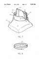
- FIG. 1is a perspective view showing a container, according to the present invention, with a cap positioned above the container;
- FIG. 2is a fragmentary view of the top part of the container with the cap in place;
- FIG. 3is an enlarged section view of the upper part of the container shown in FIG. 1;
- FIG. 4is a fragmentary view of another embodiment of a container, according to the present invention.
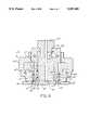
- FIG. 5is a fragmentary view, partially in cross section, showing the finish portion of a container according to the present invention, being formed in a molding machine;
- FIG. 6is a fragmentary view, similar to FIG. 5 showing the finish portion of the FIG. 4 container embodiment being formed in a molding machine.
- FIG. 7is a partial perspective, partially in section, showing another embodiment of the present invention.
- FIG. 8is a schematic view illustrating the length of thread to be molded on the inner surface of the cylindrical wall.
- FIG. 9is a sectional view showing apparatus for injection molding the spout web and annular wall of the modified invention.
- FIG. 10is a sectional view showing apparatus for injection molding the spout, web and wall portion and showing a portion of a closed blow mold with the body portion of the container blown therein.
- FIG. 11is a sectional view showing apparatus for injection molding the spout, web and wall portion with a portion of a newly formed body of the container depending therefrom.
- FIG. 12is a view similar to FIG. 11 showing initial movement of portions of said injection molding apparatus during removal therefrom of the spout, web and wall with its depending newly formed body portion.
- FIG. 13is a view similar to FIGS. 11 and 12 showing further movement of the injection molding apparatus to strip the spout, web and wall therefrom.
- a self-draining containeris generally indicated by the reference number 10. While the self-draining container 10, depicted in the drawings, is a plastic bottle specifically designed for liquids, other self-draining containers which fall within the scope of the present invention may be constructed of other materials and used to contain liquids, powders or granules.
- the self-draining container 10includes a body portion 11 which terminates in an opening 12 through which the contents of the container 10 can be dispersed.
- An integrally formed dispensing portion 14extends from and communicates with the body portion 11.
- the dispensing portion 14includes a circular wall 15 which extends annularly around the body opening 12.
- a dispensing spout 16is located within and is encircled by the wall 15.
- the dispensing spout 16includes an upper end 17 which extends above a top 18 of the wall 15.
- a connecting web 20extends between the wall 15 from an elevation below the top 18 to the dispensing spout 16.
- the web 20connects the wall 15 and the dispensing spout 16 and cooperates with the wall 15 and the dispensing spout 16 to define a channel 21 into which fluid flowing from the exterior of the dispensing spout 16 may drain when the container 10 is uprighted after it has been inverted for pouring.
- the web 20extends at least halfway around the dispensing spout 16 to prevent flow of liquid into the channel 21 when the container 10 is partially inverted to a pouring position.
- a drain opening 23is provided adjacent the channel 21. Fluid which is received in the channel 21 may drain back into the body 11 of the container 10 after the container is uprighted subsequent to pouring.
- the drain opening 23is defined by both the dispensing spout 16 and the web 20.
- the channel 21may be continuous having only a step portion with the drain being defined solely by the dispensing spout (not shown).
- a drain opening 26comprises a circular hole which extends through the web 20'.
- the drain opening 23 or the drain opening 26is in an opposed relationship to the upper end 17 of the dispensing spout 16 or 16'.
- Threads 27are formed on the inside of the circular wall 15. Similarly, threads 27' are formed on the inside wall 15' of the FIG. 4 embodiment.
- a closure or cap 30includes a top 31 and a depending sidewall 32.
- a sealing ring 33extends radially outwardly from the sidewall 32 and a cylindrical skirt 34 depends downwardly below the ring 33.
- External threads 35are formed on the exterior surface of the skirt 34 and cooperate with the threads 27 defined on the interior wall 15 of the container 10.
- the threadsmay be located on the exterior wall and mate with cap threads located on the interior of the cap.
- FIG. 1shows the cap 30 removed, while FIG. 2 shows the cap 30 in position on the container 10.
- the sealing ring 33 of the cap 30engages the top 18 of the wall 15 of the container 10 to provide a proper seal.
- the self-draining container 10may be produced within the normal cycle of a blow molding machine of a type used by the assignee of the present invention known as a BC-3 machine. No post-molding operations are needed to produce the desired self-draining finish on this type of machine.
- a portion of a BC-3 machineis generally indicated by the reference number 40. Details of a BC-3 machine method are disclosed in Sherman U.S. Pat. No. 2,804,654, which is incorporated herein by reference.
- This type of blow moldingmay be characterized as injection-extrusion blow molding and is used by the assignee of the present invention and others with a machine designated as a BC-3 machine.
- the upper neck or finish portion of the containeris first injection molded in an injection mold.
- the injection moldUpon completion of the injection molding step, the injection mold is raised from the orifice of the injection die head while a length of heated and plasticized tubing is extruded from the die head.
- the tubingis connected to the injection molded finish and is drawn upwardly as the tubing is extruded.
- blow mold halvesclose around the tubing and air is introduced through the injection mold assembly to expand the tubing in the closed mold to form the remainder of the container.
- the extrusion dieis designated by the numeral 40 and includes a bushing 41 and mandrel 42 which cooperate to define an orifice 43 through which the heated and plasticized material is expelled. Also shown is a moveable neck ring assembly 51 which is mounted (by means not shown) for movement downwardly into engagement with the orifice 43 during the injection molding step and for movement upwardly during the extrusion step to draw the oncoming tubing away from the orifice 43.
- the neck ring assembly 51includes neck ring halves 52a and 52b which can open and close radially and which have interior wall portions 53 against which the exterior surface of the annular wall 15 of the container is molded.
- a core pin 54having a passageway extending longitudinally therethrough through which pressurized air may be introduced into the extruded tubing after such tubing is enclosed within the blow mold to thereby expand the tube in the blow mold and form the body of the container.
- the core pin 54forms the interior surface of the spout 16 of the container.
- a sleeve 60encircles the core pin 54 and has a recess 61 of a configuration to form the upper end 17 and outer surface of the spout 16.
- the lower exterior portion of the sleeve 60forms the interior surface of the annular wall 15 and has a thread recess 62 in which the threads 27 are molded.
- the lower end 63 of the sleeve 60is angled such that during the injection molding step it is spaced from the mandrel for a major portion around its circumference to cooperate therewith to form the web 20 as shown at the left in FIG. 5 but is in contact with the mandrel for a minor portion as shown at the right in FIG. 5 to form the drain opening 23 (see FIG. 3) without the necessity of a post-forming operation.
- a BC-3 machinemay have a pin 64 mounted on the lower end of the sleeve 60 to form the drain opening 26 (see FIG. 4) of the self-draining container 10'.
- the self-draining container 10'may be manufactured on a BC-3 machine without the necessity of post-forming operations on the bottle finish.
- FIGS. 7-13there is shown an improved self-draining container 10" along with method and apparatus for forming and ejecting such container from the mold in which the spout, web and wall were injection molded.
- the wall 15has an internal thread 27 formed in a thread cavity 62 which may be characterized as a single thread, i.e., one having an arcuate extent on the order of one to one and one-half turns if it is desired to provide the same overlap between the leading upper end and trailing lower end.
- a modified bottle 10"having a body portion 11" and a dispensing portion 14" which includes a cylindrical wall 15", a dispensing spout 16" encircled by said wall 15” and joined thereto by a web 20" having a drain opening 23".
- the spoutincludes an upper end 17" which extends above the top 18" of the wall 15".
- the inner surface of the wall 15"has formed therein a thread 27" which extends at least two complete turns so that any section cut axially through such wall 15" will have two separate and distinct portions of the thread 27".
- FIG. 8shows schematically the length of the thread 27" as having a length slightly in excess of two full turns so that there is some overlap in the ends A and B with the result that a section taken through the wall 15" between the respective ends would pass through three thread segments.
- an extrusion die 40'having a bushing 41' and mandrel 42' which cooperate to define an orifice 43' through which heated and plasticized material is expelled.
- a moveable neck ring assembly 51'is mounted by means (not shown) for movement downwardly into engagement with the orifice 43' during the injection molding step and movement upwardly during the extrusion step to draw the oncoming tubing away from the orifice 43'.
- the neck ring assembly 51'includes neck ring halves 52a' and 52b' which can open and close radially and which have interior wall portions 53' against which the exterior surface of the wall 15" of the container is molded.
- a core pin 54'having a passageway extending longitudinally therethrough through which pressurized air may be introduced into the extruded tubing after such tubing is enclosed in a blow mold 85 to thereby expand the tube in the blow mold and form the body 11" of the container 10". (See FIG. 10).
- the core pin 54'forms the interior surface of the spout 16" of the container.
- the core pin 54'has a recessed area 78 extending from an upper ledge 79 to a lower ledge 80.
- a sleeve 60'encircles the core pin 54' and has a recess 61' of a configuration to form the upper end 17" and the outer surface of the spout 16".
- the lower exterior portion of the sleeve 60'forms the interior surface of the wall 15" and has a thread recess 62' in which the thread 27" is molded.
- the length of the thread recess 62'is such as to provide at least two complete turns (i.e., 720°) so that in any axial section of the wall 15", there will always be at least two thread segments. This is true irrespective of where the axial section is taken throughout the entire 360° of the wall 15".
- the lower end 63' of the sleeve 60'is angled such that during the injection molded step, it is spaced from the mandrel for a major portion around its circumference to cooperate therewith to form the web 20".
- the upper end of the sleeve 60'is provided an inwardly extending flange 81 which is positioned in the recessed area 78 of the core pin 54'.
- a stripper ring 82encircles the sleeve 60' and has a lower molding surface 83 which forms the upper surface 18" of the wall 15".
- the spout 16", web 20", and wall 15"may be removed from the neck ring assembly 51'. This is normally done after the halves of the blow mold 85 in which the body portion 11" was molded have been opened. Such removal is accomplished by the sequence of steps hereinafter described. Initially, the neck ring halves 52a' and 52b' are moved to the partially open position shown in FIG. 12. Simultaneously with or immediately following the partial opening of the neck ring halves 52a' and 52b', the core pin 54' is elevated to partially withdraw it from the spout 16".
- the core pin 54'is moved further upwardly so that its ledge 80 engages the inwardly extending flange 81 of the sleeve 60'.
- Such engagementfollowed by continued upward movement of the core pin 54' draws the sleeve 60' upwardly.
- Engagement of the top 18" of the wall 15" against the lower molding surface 83 of the stripper ring 82prevents upward movement of the container 10" as the sleeve 60' moves upwardly and thus causes the wall 15" with its internal thread 27" to be axially stripped therefrom.
Landscapes
- Engineering & Computer Science (AREA)
- Mechanical Engineering (AREA)
- Manufacturing & Machinery (AREA)
- Physics & Mathematics (AREA)
- Geometry (AREA)
- Containers Having Bodies Formed In One Piece (AREA)
Abstract
Description
Claims (15)
Priority Applications (1)
| Application Number | Priority Date | Filing Date | Title |
|---|---|---|---|
| US07/834,069US5207356A (en) | 1988-02-25 | 1992-02-10 | Self-draining container |
Applications Claiming Priority (4)
| Application Number | Priority Date | Filing Date | Title |
|---|---|---|---|
| US16047888A | 1988-02-25 | 1988-02-25 | |
| US31431289A | 1989-02-22 | 1989-02-22 | |
| US07/533,632US5114659A (en) | 1988-02-25 | 1990-06-05 | Blow molding method for forming a one-piece self-draining container |
| US07/834,069US5207356A (en) | 1988-02-25 | 1992-02-10 | Self-draining container |
Related Parent Applications (1)
| Application Number | Title | Priority Date | Filing Date |
|---|---|---|---|
| US07/533,632DivisionUS5114659A (en) | 1988-02-25 | 1990-06-05 | Blow molding method for forming a one-piece self-draining container |
Publications (1)
| Publication Number | Publication Date |
|---|---|
| US5207356Atrue US5207356A (en) | 1993-05-04 |
Family
ID=27496426
Family Applications (1)
| Application Number | Title | Priority Date | Filing Date |
|---|---|---|---|
| US07/834,069Expired - LifetimeUS5207356A (en) | 1988-02-25 | 1992-02-10 | Self-draining container |
Country Status (1)
| Country | Link |
|---|---|
| US (1) | US5207356A (en) |
Cited By (54)
| Publication number | Priority date | Publication date | Assignee | Title |
|---|---|---|---|---|
| US5431306A (en)* | 1993-12-31 | 1995-07-11 | Innovative Molding, Inc. | Drain back container with internal thread |
| US5566862A (en)* | 1994-10-24 | 1996-10-22 | Owens-Illinois Closure Inc. | Liquid containing and dispensing package |
| WO1998045207A1 (en)* | 1997-04-04 | 1998-10-15 | Graham Packaging Corporation | Plastic container dispensing fitment |
| US5964383A (en)* | 1997-04-22 | 1999-10-12 | Graham Packaging Company, L.P. | Pinch neck pour spout container |
| US5988460A (en)* | 1998-03-30 | 1999-11-23 | Owens-Brockway Plastic Products Inc. | Molded plastic container and container package with integral pour spout |
| US6032829A (en)* | 1998-05-21 | 2000-03-07 | Owens-Illinois Closure Inc. | Container and closure package and method of making same |
| US6085949A (en)* | 1998-05-05 | 2000-07-11 | Liquid Container L.P. | Container with molded-in directional pour guide |
| WO2000040475A1 (en) | 1998-12-30 | 2000-07-13 | Unilever Plc | Manufactured pour spout fitment and container |
| US6123231A (en)* | 1998-07-13 | 2000-09-26 | Owens-Brockway Plastic Products Inc. | Plastic container with drain back spout and method and apparatus for making same |
| US6209762B1 (en) | 1998-01-29 | 2001-04-03 | Owens-Illinois Closure Inc. | Dispensing package and method of use |
| USD449535S1 (en) | 2000-04-20 | 2001-10-23 | Owens-Brockway Plastic Products Inc. | Container |
| US6352179B1 (en)* | 1999-08-12 | 2002-03-05 | Eva Denmark A/S | Pouring spout for mounting on a container |
| US6398076B1 (en)* | 1998-12-30 | 2002-06-04 | Unilever Home & Personal Care Usa, Division Of Conopco, Inc. | Fitment and bottle |
| US6530500B2 (en) | 1999-07-08 | 2003-03-11 | The Sherwin-Williams Company | Storage and dispensing container for viscous fluids, paints and the like, and method of minimizing dripping |
| USD472145S1 (en) | 2001-08-14 | 2003-03-25 | Nottingham-Spirk Partners, Llc | Paint container lid |
| USD473790S1 (en) | 2001-08-14 | 2003-04-29 | Nottingham-Spirk Partners, Llc | Paint container insert |
| US20030188986A1 (en)* | 2000-04-11 | 2003-10-09 | Wylie Arun M. | Container |
| USD480973S1 (en) | 2001-08-14 | 2003-10-21 | Nsi Innovation Llp | Design for a round paint container |
| USD482973S1 (en) | 2001-08-14 | 2003-12-02 | Nsi Innovation Llc | Square paint container |
| US6659310B1 (en)* | 2000-03-14 | 2003-12-09 | The Dial Corporation | Product dispensing and drainback fitting |
| US20040011831A1 (en)* | 2002-07-03 | 2004-01-22 | Mcdonald Robert E. | Plastic paint container having a cube-shaped body |
| US20050087548A1 (en)* | 2003-10-24 | 2005-04-28 | Erie County Plastics Corporation | Drain-back snap-on pour spout fitment closure |
| US20050139609A1 (en)* | 2003-12-30 | 2005-06-30 | Unilever Home & Personal Care Usa | Pour spout fitment and container |
| USD510866S1 (en) | 2001-08-14 | 2005-10-25 | The Sherwin-Williams Company | Round paint container |
| USD511101S1 (en) | 2001-08-14 | 2005-11-01 | The Sherwin-Williams Company | Round paint container with handle |
| US6983862B2 (en) | 2001-04-18 | 2006-01-10 | The Sherwin-Williams Company | Container and lid assembly |
| US20060032872A1 (en)* | 2004-08-12 | 2006-02-16 | The Procter & Gamble Company | Package for pouring a granular product |
| US7014078B2 (en) | 2001-12-05 | 2006-03-21 | Masterchem Industries Llc | Container |
| US20060073233A1 (en)* | 2003-05-15 | 2006-04-06 | Struble Douglas S | Method and apparatus for blow molding hollow plastic containers |
| USD518731S1 (en) | 2005-01-05 | 2006-04-11 | The Clorox Company | Bottle |
| US20060097006A1 (en)* | 2005-10-11 | 2006-05-11 | Erie County Plastics Corporation | Pour spout fitment with internal cut off |
| US20060131330A1 (en)* | 2004-12-21 | 2006-06-22 | Erie County Plastics Corporation | Drain-back spout fitment closure with drip-less pour tip |
| US20060163252A1 (en)* | 2005-01-24 | 2006-07-27 | Letica Corporation | Container |
| US20070023460A1 (en)* | 2005-07-27 | 2007-02-01 | Ochen Industries, Llc | Liquid conveying bottle top |
| US20070095784A1 (en)* | 2005-10-28 | 2007-05-03 | Conopco, Inc. | Package for liquid laundry products |
| US20070095779A1 (en)* | 2005-10-28 | 2007-05-03 | Conopco, Inc., D/B/A Unilever | Packaged liquid laundry compositions |
| US20070210123A1 (en)* | 2006-03-07 | 2007-09-13 | Penny Michael E | Container having blown pour spout |
| US20070235477A1 (en)* | 2006-04-11 | 2007-10-11 | Penny Michael E | Container having blown pour spout |
| US20070290013A1 (en)* | 2004-08-12 | 2007-12-20 | Satoshi Yamane | Package for pouring a product |
| US20070295767A1 (en)* | 2006-06-23 | 2007-12-27 | Antonio Victor Angelo | Package for pouring a product |
| USD563228S1 (en) | 2001-08-14 | 2008-03-04 | The Sherwin-Williams Company | Container for coating materials |
| US20080110849A1 (en)* | 2006-11-10 | 2008-05-15 | Rwachsberg Holdings, Inc. | Bottle and cap with anti-glug feature |
| US20080230572A1 (en)* | 2007-03-20 | 2008-09-25 | The Procter & Gamble Company | Package for pouring a product |
| US20080283552A1 (en)* | 2007-05-17 | 2008-11-20 | Penny Michael E | Molded preform and container having integrated pour spout |
| US20090045224A1 (en)* | 2007-08-17 | 2009-02-19 | Joel Faaborg | Liquid product pouring and measuring package with drain-back spout fitment and tight-sealing measuring cup assembly |
| US20090250465A1 (en)* | 2008-04-04 | 2009-10-08 | Stokely-Van Camp, Inc. | Closure With Flexible Diaphragm |
| US20110042389A1 (en)* | 2008-02-05 | 2011-02-24 | Aisapack Holdings S.A. | Tube head and production method |
| US20110062109A1 (en)* | 2008-11-06 | 2011-03-17 | Richard Lawrence Horstman | Container with an Integrated Spout |
| US20110089195A1 (en)* | 2007-05-17 | 2011-04-21 | Amcor Limited | Molded preform and container having integrated pour spout |
| US20120085760A1 (en)* | 2005-09-08 | 2012-04-12 | Sheldon Yourist | Simultaneously Blow Molded Container and Closure |
| US8663419B2 (en) | 2010-11-30 | 2014-03-04 | Ecologic | Manual container assembly and liner integration fixture for pulp-molded shell with polymer liner container systems |
| EP3587061A1 (en)* | 2018-06-27 | 2020-01-01 | Resilux N.V. | Preform and container adapted for accommodating an insert piece, with methods and apparatus for their production |
| USD899259S1 (en)* | 2019-10-23 | 2020-10-20 | Target Brands, Inc. | Bottle |
| US20220041346A1 (en)* | 2018-09-14 | 2022-02-10 | Alpla Werke Alwin Lehner Gmbh & Co. Kg | Plastic container comprising a pouring element |
Citations (29)
| Publication number | Priority date | Publication date | Assignee | Title |
|---|---|---|---|---|
| DE244327C (en)* | ||||
| CH188590A (en)* | 1936-06-29 | 1937-01-15 | S Altschul Peter | Bottle pourer made of synthetic resin. |
| US2601039A (en)* | 1949-12-01 | 1952-06-17 | Livingstone Jay Gould | Pouring spout |
| GB678883A (en)* | 1950-07-14 | 1952-09-10 | Alfred George Mill | Improvements relating to drip-retaining means for bottles and other containers |
| US2743844A (en)* | 1956-05-01 | livingstone | ||
| US2763403A (en)* | 1953-06-16 | 1956-09-18 | Jay G Livingstone | Fittings |
| FR1125509A (en)* | 1955-03-23 | 1956-10-31 | Pont Du Diable Soc Du | Pouring cap |
| US2793790A (en)* | 1956-03-09 | 1957-05-28 | Maurice C Kahler | Dripless pitcher |
| US2804654A (en)* | 1954-03-03 | 1957-09-03 | Owens Illinois Glass Co | Method of forming hollow plastic articles |
| US2911673A (en)* | 1955-08-03 | 1959-11-10 | Owens Illinois Glass Co | Apparatus for molding containers with restricted neck openings |
| US3029471A (en)* | 1959-10-14 | 1962-04-17 | Owens Illinois Glass Co | Method and apparatus for making plastic articles |
| US3364521A (en)* | 1965-09-01 | 1968-01-23 | Emery I. Valyi | Apparatus for blow molding seamless hollow objects |
| US3537676A (en)* | 1967-12-20 | 1970-11-03 | Valve Corp Of America | Mold apparatus for closure with integral cap |
| US3833150A (en)* | 1971-06-16 | 1974-09-03 | Patings W Visser | Pouring stop |
| JPS51129658A (en)* | 1975-04-30 | 1976-11-11 | Matsushita Electric Works Ltd | Reed relay |
| US4115496A (en)* | 1977-06-28 | 1978-09-19 | Owens-Illinois, Inc. | Method for molding a threaded bunghole |
| GB2094220A (en)* | 1981-02-03 | 1982-09-15 | Katashi Aoki | Injection stretching and blow moulding machine |
| US4550862A (en)* | 1982-11-17 | 1985-11-05 | The Procter & Gamble Company | Liquid product pouring and measuring package with self draining feature |
| US4578028A (en)* | 1984-12-06 | 1986-03-25 | The Procter & Gamble Company | Expandable core pin for blow-molding a container having a neck-portion with internal attachment means |
| US4616759A (en)* | 1985-11-08 | 1986-10-14 | Darrell Mahler | Liquid-dispensing container assembly |
| US4640855A (en)* | 1985-10-25 | 1987-02-03 | Owens-Illinois, Inc. | Plastic container with integral spout |
| US4671421A (en)* | 1986-03-06 | 1987-06-09 | Owens-Illinois, Inc. | Plastic container |
| US4696416A (en)* | 1984-09-28 | 1987-09-29 | The Procter & Gamble Company | Liquid product dispensing package with self draining feature employing drip concentrator |
| US4706829A (en)* | 1986-02-07 | 1987-11-17 | Owens-Illinois Closure Inc. | Liquid containing and dispensing package |
| US4929410A (en)* | 1984-12-06 | 1990-05-29 | The Procter & Gamble Company | Method for blow-molding a container having a neck-portion with internal attachment means |
| US4941815A (en)* | 1989-01-19 | 1990-07-17 | Sunbeam Plastics Corporation | Injection-blow molding apparatus |
| US4989757A (en)* | 1988-02-25 | 1991-02-05 | Owens-Illinois Plastic Products Inc. | Plastic container with self-draining feature |
| US5020892A (en)* | 1989-09-25 | 1991-06-04 | Burris Company, Inc. | Aperture control for telescopic gunsight |
| US5108009A (en)* | 1986-02-12 | 1992-04-28 | Lever Brothers Company, Division Of Conopco, Inc. | Leak and drip resistant storage dispensing and measuring package |
- 1992
- 1992-02-10USUS07/834,069patent/US5207356A/ennot_activeExpired - Lifetime
Patent Citations (29)
| Publication number | Priority date | Publication date | Assignee | Title |
|---|---|---|---|---|
| US2743844A (en)* | 1956-05-01 | livingstone | ||
| DE244327C (en)* | ||||
| CH188590A (en)* | 1936-06-29 | 1937-01-15 | S Altschul Peter | Bottle pourer made of synthetic resin. |
| US2601039A (en)* | 1949-12-01 | 1952-06-17 | Livingstone Jay Gould | Pouring spout |
| GB678883A (en)* | 1950-07-14 | 1952-09-10 | Alfred George Mill | Improvements relating to drip-retaining means for bottles and other containers |
| US2763403A (en)* | 1953-06-16 | 1956-09-18 | Jay G Livingstone | Fittings |
| US2804654A (en)* | 1954-03-03 | 1957-09-03 | Owens Illinois Glass Co | Method of forming hollow plastic articles |
| FR1125509A (en)* | 1955-03-23 | 1956-10-31 | Pont Du Diable Soc Du | Pouring cap |
| US2911673A (en)* | 1955-08-03 | 1959-11-10 | Owens Illinois Glass Co | Apparatus for molding containers with restricted neck openings |
| US2793790A (en)* | 1956-03-09 | 1957-05-28 | Maurice C Kahler | Dripless pitcher |
| US3029471A (en)* | 1959-10-14 | 1962-04-17 | Owens Illinois Glass Co | Method and apparatus for making plastic articles |
| US3364521A (en)* | 1965-09-01 | 1968-01-23 | Emery I. Valyi | Apparatus for blow molding seamless hollow objects |
| US3537676A (en)* | 1967-12-20 | 1970-11-03 | Valve Corp Of America | Mold apparatus for closure with integral cap |
| US3833150A (en)* | 1971-06-16 | 1974-09-03 | Patings W Visser | Pouring stop |
| JPS51129658A (en)* | 1975-04-30 | 1976-11-11 | Matsushita Electric Works Ltd | Reed relay |
| US4115496A (en)* | 1977-06-28 | 1978-09-19 | Owens-Illinois, Inc. | Method for molding a threaded bunghole |
| GB2094220A (en)* | 1981-02-03 | 1982-09-15 | Katashi Aoki | Injection stretching and blow moulding machine |
| US4550862A (en)* | 1982-11-17 | 1985-11-05 | The Procter & Gamble Company | Liquid product pouring and measuring package with self draining feature |
| US4696416A (en)* | 1984-09-28 | 1987-09-29 | The Procter & Gamble Company | Liquid product dispensing package with self draining feature employing drip concentrator |
| US4929410A (en)* | 1984-12-06 | 1990-05-29 | The Procter & Gamble Company | Method for blow-molding a container having a neck-portion with internal attachment means |
| US4578028A (en)* | 1984-12-06 | 1986-03-25 | The Procter & Gamble Company | Expandable core pin for blow-molding a container having a neck-portion with internal attachment means |
| US4640855A (en)* | 1985-10-25 | 1987-02-03 | Owens-Illinois, Inc. | Plastic container with integral spout |
| US4616759A (en)* | 1985-11-08 | 1986-10-14 | Darrell Mahler | Liquid-dispensing container assembly |
| US4706829A (en)* | 1986-02-07 | 1987-11-17 | Owens-Illinois Closure Inc. | Liquid containing and dispensing package |
| US5108009A (en)* | 1986-02-12 | 1992-04-28 | Lever Brothers Company, Division Of Conopco, Inc. | Leak and drip resistant storage dispensing and measuring package |
| US4671421A (en)* | 1986-03-06 | 1987-06-09 | Owens-Illinois, Inc. | Plastic container |
| US4989757A (en)* | 1988-02-25 | 1991-02-05 | Owens-Illinois Plastic Products Inc. | Plastic container with self-draining feature |
| US4941815A (en)* | 1989-01-19 | 1990-07-17 | Sunbeam Plastics Corporation | Injection-blow molding apparatus |
| US5020892A (en)* | 1989-09-25 | 1991-06-04 | Burris Company, Inc. | Aperture control for telescopic gunsight |
Cited By (98)
| Publication number | Priority date | Publication date | Assignee | Title |
|---|---|---|---|---|
| US5603787A (en)* | 1993-12-31 | 1997-02-18 | Innovative Molding, Inc. | Drain back container assembly |
| US5431306A (en)* | 1993-12-31 | 1995-07-11 | Innovative Molding, Inc. | Drain back container with internal thread |
| US5566862A (en)* | 1994-10-24 | 1996-10-22 | Owens-Illinois Closure Inc. | Liquid containing and dispensing package |
| WO1998045207A1 (en)* | 1997-04-04 | 1998-10-15 | Graham Packaging Corporation | Plastic container dispensing fitment |
| US5964383A (en)* | 1997-04-22 | 1999-10-12 | Graham Packaging Company, L.P. | Pinch neck pour spout container |
| US6209762B1 (en) | 1998-01-29 | 2001-04-03 | Owens-Illinois Closure Inc. | Dispensing package and method of use |
| US5988460A (en)* | 1998-03-30 | 1999-11-23 | Owens-Brockway Plastic Products Inc. | Molded plastic container and container package with integral pour spout |
| US6085949A (en)* | 1998-05-05 | 2000-07-11 | Liquid Container L.P. | Container with molded-in directional pour guide |
| US6032829A (en)* | 1998-05-21 | 2000-03-07 | Owens-Illinois Closure Inc. | Container and closure package and method of making same |
| US6223946B1 (en) | 1998-05-21 | 2001-05-01 | Owens Illinois Closure Inc. | Closure for container and closure package and method of making same |
| US6123231A (en)* | 1998-07-13 | 2000-09-26 | Owens-Brockway Plastic Products Inc. | Plastic container with drain back spout and method and apparatus for making same |
| AU750546B2 (en)* | 1998-07-13 | 2002-07-18 | Owens-Brockway Plastic Products Inc. | Plastic container with drain back spout and method and apparatus for making same |
| US6500380B1 (en) | 1998-07-13 | 2002-12-31 | Owens Brockway Plastic Products Inc. | Method and apparatus for making a plastic container with drain back spout |
| WO2000040475A1 (en) | 1998-12-30 | 2000-07-13 | Unilever Plc | Manufactured pour spout fitment and container |
| US6398076B1 (en)* | 1998-12-30 | 2002-06-04 | Unilever Home & Personal Care Usa, Division Of Conopco, Inc. | Fitment and bottle |
| US7703641B2 (en) | 1999-07-08 | 2010-04-27 | The Sherwin-Williams Company | Storage and dispensing container for paint |
| US6634525B2 (en) | 1999-07-08 | 2003-10-21 | The Sherwin-Williams Company | Storage and dispensing container for paint |
| US6530500B2 (en) | 1999-07-08 | 2003-03-11 | The Sherwin-Williams Company | Storage and dispensing container for viscous fluids, paints and the like, and method of minimizing dripping |
| US20050028884A1 (en)* | 1999-07-08 | 2005-02-10 | The Sherwin Williams Company | Storage and dispensing container for paint |
| US7325687B2 (en) | 1999-07-08 | 2008-02-05 | The Sherwin-Williams Company | Storage and dispensing container for paint |
| US6352179B1 (en)* | 1999-08-12 | 2002-03-05 | Eva Denmark A/S | Pouring spout for mounting on a container |
| US6659310B1 (en)* | 2000-03-14 | 2003-12-09 | The Dial Corporation | Product dispensing and drainback fitting |
| US20060288660A1 (en)* | 2000-04-11 | 2006-12-28 | Wylie Arun M | Container |
| US20060289326A1 (en)* | 2000-04-11 | 2006-12-28 | Wylie Arun M | Container |
| US20070074487A1 (en)* | 2000-04-11 | 2007-04-05 | Wylie Arun M | Container |
| US20070000804A1 (en)* | 2000-04-11 | 2007-01-04 | Wylie Arun M | Container |
| US20030188986A1 (en)* | 2000-04-11 | 2003-10-09 | Wylie Arun M. | Container |
| US7032756B2 (en) | 2000-04-11 | 2006-04-25 | Wylie Arun M | Container |
| US20060289543A1 (en)* | 2000-04-11 | 2006-12-28 | Wylie Arun M | Container |
| US20060016713A1 (en)* | 2000-04-11 | 2006-01-26 | Wylie Arun M | Container |
| US20060283756A1 (en)* | 2000-04-11 | 2006-12-21 | Wylie Arun M | Container |
| US20060163107A1 (en)* | 2000-04-11 | 2006-07-27 | Wylie Arun M | Container |
| US20060163106A1 (en)* | 2000-04-11 | 2006-07-27 | Wylie Arun M | Container |
| US20060163108A1 (en)* | 2000-04-11 | 2006-07-27 | Wylie Arun M | Container |
| US20060163105A1 (en)* | 2000-04-11 | 2006-07-27 | Wylie Arun M | Container |
| USD449535S1 (en) | 2000-04-20 | 2001-10-23 | Owens-Brockway Plastic Products Inc. | Container |
| US6983862B2 (en) | 2001-04-18 | 2006-01-10 | The Sherwin-Williams Company | Container and lid assembly |
| USD482973S1 (en) | 2001-08-14 | 2003-12-02 | Nsi Innovation Llc | Square paint container |
| USD473790S1 (en) | 2001-08-14 | 2003-04-29 | Nottingham-Spirk Partners, Llc | Paint container insert |
| USD472145S1 (en) | 2001-08-14 | 2003-03-25 | Nottingham-Spirk Partners, Llc | Paint container lid |
| USD573475S1 (en) | 2001-08-14 | 2008-07-22 | The Sherwin-Williams Company | Square paint container |
| USD563228S1 (en) | 2001-08-14 | 2008-03-04 | The Sherwin-Williams Company | Container for coating materials |
| USD480973S1 (en) | 2001-08-14 | 2003-10-21 | Nsi Innovation Llp | Design for a round paint container |
| USD500953S1 (en) | 2001-08-14 | 2005-01-18 | The Sherwin-Williams Company | Container for coating materials |
| USD510866S1 (en) | 2001-08-14 | 2005-10-25 | The Sherwin-Williams Company | Round paint container |
| USD511101S1 (en) | 2001-08-14 | 2005-11-01 | The Sherwin-Williams Company | Round paint container with handle |
| US7156265B2 (en) | 2001-12-05 | 2007-01-02 | Masterchem Industries Llc | Container |
| US7014078B2 (en) | 2001-12-05 | 2006-03-21 | Masterchem Industries Llc | Container |
| US7036693B2 (en) | 2001-12-05 | 2006-05-02 | Masterchem Industries Llc | Paint container |
| US20040011831A1 (en)* | 2002-07-03 | 2004-01-22 | Mcdonald Robert E. | Plastic paint container having a cube-shaped body |
| US6896156B2 (en) | 2002-07-03 | 2005-05-24 | The Sherwin-Williams Company | Plastic paint container having a cube-shaped body |
| US20060073233A1 (en)* | 2003-05-15 | 2006-04-06 | Struble Douglas S | Method and apparatus for blow molding hollow plastic containers |
| US7153127B2 (en) | 2003-05-15 | 2006-12-26 | Graham Packaging Plastic Products Inc. | Method and apparatus for blow molding hollow plastic containers |
| US20050087548A1 (en)* | 2003-10-24 | 2005-04-28 | Erie County Plastics Corporation | Drain-back snap-on pour spout fitment closure |
| US6923341B2 (en) | 2003-10-24 | 2005-08-02 | Erie County Plastics Corporation | Drain-back snap-on pour spout fitment closure |
| US6968980B2 (en)* | 2003-12-30 | 2005-11-29 | Unilever Home & Personal Care Usa, A Division Of Conopco, Inc. | Pour spout fitment and container |
| US20050139609A1 (en)* | 2003-12-30 | 2005-06-30 | Unilever Home & Personal Care Usa | Pour spout fitment and container |
| US20060032872A1 (en)* | 2004-08-12 | 2006-02-16 | The Procter & Gamble Company | Package for pouring a granular product |
| US20070290013A1 (en)* | 2004-08-12 | 2007-12-20 | Satoshi Yamane | Package for pouring a product |
| US20060131330A1 (en)* | 2004-12-21 | 2006-06-22 | Erie County Plastics Corporation | Drain-back spout fitment closure with drip-less pour tip |
| US7686188B2 (en)* | 2004-12-21 | 2010-03-30 | Berry Plastics Corporation | Drain-back spout fitment closure with drip-less pour tip |
| USD518731S1 (en) | 2005-01-05 | 2006-04-11 | The Clorox Company | Bottle |
| US20060163252A1 (en)* | 2005-01-24 | 2006-07-27 | Letica Corporation | Container |
| US20070023460A1 (en)* | 2005-07-27 | 2007-02-01 | Ochen Industries, Llc | Liquid conveying bottle top |
| US20120085760A1 (en)* | 2005-09-08 | 2012-04-12 | Sheldon Yourist | Simultaneously Blow Molded Container and Closure |
| US9956715B2 (en)* | 2005-09-08 | 2018-05-01 | Graham Packaging Company, L.P. | Simultaneously blow molded container and closure |
| US20060097006A1 (en)* | 2005-10-11 | 2006-05-11 | Erie County Plastics Corporation | Pour spout fitment with internal cut off |
| US20070095784A1 (en)* | 2005-10-28 | 2007-05-03 | Conopco, Inc. | Package for liquid laundry products |
| USD627655S1 (en) | 2005-10-28 | 2010-11-23 | The Sun Products Corporation | Bottle |
| USD662423S1 (en) | 2005-10-28 | 2012-06-26 | The Sun Products Corporation | Bottle |
| USD637916S1 (en) | 2005-10-28 | 2011-05-17 | The Sun Products Corporation | Bottle |
| US7665638B2 (en)* | 2005-10-28 | 2010-02-23 | The Sun Products Corporation | Packaged liquid laundry compositions |
| US20070095779A1 (en)* | 2005-10-28 | 2007-05-03 | Conopco, Inc., D/B/A Unilever | Packaged liquid laundry compositions |
| US20100001440A1 (en)* | 2006-03-07 | 2010-01-07 | Amcor Limited | Method of making a container having blown pour spout |
| US20070210123A1 (en)* | 2006-03-07 | 2007-09-13 | Penny Michael E | Container having blown pour spout |
| US20070235477A1 (en)* | 2006-04-11 | 2007-10-11 | Penny Michael E | Container having blown pour spout |
| US20070295767A1 (en)* | 2006-06-23 | 2007-12-27 | Antonio Victor Angelo | Package for pouring a product |
| US20080110849A1 (en)* | 2006-11-10 | 2008-05-15 | Rwachsberg Holdings, Inc. | Bottle and cap with anti-glug feature |
| US8079484B2 (en)* | 2006-11-10 | 2011-12-20 | Rwachsberg Holdings, Inc. | Bottle and cap with anti-glug feature |
| US20080230572A1 (en)* | 2007-03-20 | 2008-09-25 | The Procter & Gamble Company | Package for pouring a product |
| US20110089195A1 (en)* | 2007-05-17 | 2011-04-21 | Amcor Limited | Molded preform and container having integrated pour spout |
| US8177098B2 (en)* | 2007-05-17 | 2012-05-15 | Amcor Limited | Molded preform and container having integrated pour spout |
| US20080283552A1 (en)* | 2007-05-17 | 2008-11-20 | Penny Michael E | Molded preform and container having integrated pour spout |
| US8955716B2 (en) | 2007-05-17 | 2015-02-17 | Amcor Limited | Molded preform and container having integrated pour spout |
| US7959034B2 (en) | 2007-08-17 | 2011-06-14 | The Dial Corporation | Liquid product pouring and measuring package with drain-back spout fitment and tight-sealing measuring cup assembly |
| US20090045224A1 (en)* | 2007-08-17 | 2009-02-19 | Joel Faaborg | Liquid product pouring and measuring package with drain-back spout fitment and tight-sealing measuring cup assembly |
| US20110042389A1 (en)* | 2008-02-05 | 2011-02-24 | Aisapack Holdings S.A. | Tube head and production method |
| US20090250465A1 (en)* | 2008-04-04 | 2009-10-08 | Stokely-Van Camp, Inc. | Closure With Flexible Diaphragm |
| US8430259B2 (en) | 2008-04-04 | 2013-04-30 | Stokely-Van Camp, Inc. | Closure with flexible diaphragm |
| US20110062109A1 (en)* | 2008-11-06 | 2011-03-17 | Richard Lawrence Horstman | Container with an Integrated Spout |
| US8663419B2 (en) | 2010-11-30 | 2014-03-04 | Ecologic | Manual container assembly and liner integration fixture for pulp-molded shell with polymer liner container systems |
| US9126719B2 (en) | 2010-11-30 | 2015-09-08 | Ecologic | Manual container assembly and liner integration fixture for pulp-molded shell with polymer liner container systems |
| EP3587061A1 (en)* | 2018-06-27 | 2020-01-01 | Resilux N.V. | Preform and container adapted for accommodating an insert piece, with methods and apparatus for their production |
| WO2020003185A1 (en)* | 2018-06-27 | 2020-01-02 | Resilux N.V. | Preform and container adapted for accommodating an insert piece, with methods and apparatus for their production |
| US11813786B2 (en) | 2018-06-27 | 2023-11-14 | Resilux N.V. | Preform and container adapted for accommodating an insert piece, with methods and apparatus for their production |
| US20220041346A1 (en)* | 2018-09-14 | 2022-02-10 | Alpla Werke Alwin Lehner Gmbh & Co. Kg | Plastic container comprising a pouring element |
| US12297012B2 (en)* | 2018-09-14 | 2025-05-13 | Alpla Werke Alwin Lehner Gmbh & Co. Kg | Plastic container comprising a pouring element |
| USD899259S1 (en)* | 2019-10-23 | 2020-10-20 | Target Brands, Inc. | Bottle |
Similar Documents
| Publication | Publication Date | Title |
|---|---|---|
| US5207356A (en) | Self-draining container | |
| US5114659A (en) | Blow molding method for forming a one-piece self-draining container | |
| US4989757A (en) | Plastic container with self-draining feature | |
| AU596044B1 (en) | Liquid containing and dispensing package | |
| US6123231A (en) | Plastic container with drain back spout and method and apparatus for making same | |
| US5901865A (en) | Hermetically sealed container with frangible web and locking lugs and method and apparatus for making same | |
| US4863067A (en) | Plastic container with self-draining feature | |
| US7001564B1 (en) | Dual-chamber container and closure package | |
| HK1000591B (en) | Plastic container with self-draining feature | |
| EP0329883B1 (en) | Plastic container with self-draining feature | |
| US4545953A (en) | Method for making an extrusion blow molded no drip lip | |
| US6602459B1 (en) | Dual-chamber container, and method and apparatus for its manufacture | |
| US5261567A (en) | Squeeze package which can be inverted to dispense liquids | |
| EP0329881B1 (en) | Self-draining container | |
| HK1000592B (en) | Self-draining container | |
| US6077471A (en) | Mold for forming a container having a continuous neck finish and method for using same | |
| HK1000590B (en) | Plastic container with self-draining feature | |
| NZ235769A (en) | Method for moulding a plastics, self-draining container |
Legal Events
| Date | Code | Title | Description |
|---|---|---|---|
| STCF | Information on status: patent grant | Free format text:PATENTED CASE | |
| FPAY | Fee payment | Year of fee payment:4 | |
| FPAY | Fee payment | Year of fee payment:8 | |
| FEPP | Fee payment procedure | Free format text:PAYOR NUMBER ASSIGNED (ORIGINAL EVENT CODE: ASPN); ENTITY STATUS OF PATENT OWNER: LARGE ENTITY | |
| FPAY | Fee payment | Year of fee payment:12 | |
| AS | Assignment | Owner name:DEUTSCHE BANK AG CAYMAN ISLANDS BRANCH AS SECOND-L Free format text:GRANT OF SECURITY INTEREST;ASSIGNOR:GRAHAM PACKAGING COMPANY, L.P.;REEL/FRAME:015552/0299 Effective date:20041007 Owner name:DEUTSCHE BANK AG CAYMAN ISLANDS BRANCH, NEW JERSEY Free format text:GRANT OF SECURITY INTEREST;ASSIGNOR:GRAHAM PACKAGING COMPANY, L.P.;REEL/FRAME:015980/0213 Effective date:20041007 | |
| AS | Assignment | Owner name:GRAHAM PACKAGING COMPANY, L.P., PENNSYLVANIA Free format text:PATENT RELEASE;ASSIGNOR:DEUTSCHE BANK AG, CAYMAN ISLANDS BRANCH, AS COLLATERAL AGENT;REEL/FRAME:019140/0509 Effective date:20070330 | |
| AS | Assignment | Owner name:GRAHAM PACKAGING COMPANY, L.P., PENNSYLVANIA Free format text:RELEASE OF SECURITY INTERESTS;ASSIGNOR:DEUTSCHE BANK AG, GAYMAN ISLANDS BRANCH, AS COLLATERAL AGENT;REEL/FRAME:027011/0572 Effective date:20110908 | |
| AS | Assignment | Owner name:GRAHAM PACKAGING COMPANY, L.P., PENNSYLVANIA Free format text:RELEASE OF SECURITY INTEREST IN CERTAIN PATENT COLLATERAL;ASSIGNOR:DEUTSCHE BANK AG CAYMAN ISLANDS BRANCH, AS COLLATERAL AGENT AND GRANTEE;REEL/FRAME:053414/0001 Effective date:20200805 |