US5205831A - Compression gasket for y-connector - Google Patents
Compression gasket for y-connectorDownload PDFInfo
- Publication number
- US5205831A US5205831AUS07/688,176US68817691AUS5205831AUS 5205831 AUS5205831 AUS 5205831AUS 68817691 AUS68817691 AUS 68817691AUS 5205831 AUS5205831 AUS 5205831A
- Authority
- US
- United States
- Prior art keywords
- connector
- guidewire
- gasket
- catheter
- compression
- Prior art date
- Legal status (The legal status is an assumption and is not a legal conclusion. Google has not performed a legal analysis and makes no representation as to the accuracy of the status listed.)
- Expired - Lifetime
Links
- 230000006835compressionEffects0.000titleclaimsabstractdescription48
- 238000007906compressionMethods0.000titleclaimsabstractdescription48
- 239000011521glassSubstances0.000claimsdescription9
- 210000001124body fluidAnatomy0.000abstractdescription5
- 239000008280bloodSubstances0.000abstractdescription3
- 210000004369bloodAnatomy0.000abstractdescription3
- 238000000034methodMethods0.000description10
- 229920002457flexible plasticPolymers0.000description7
- 238000002347injectionMethods0.000description6
- 239000007924injectionSubstances0.000description6
- 238000007789sealingMethods0.000description6
- 210000003813thumbAnatomy0.000description6
- 239000000463materialSubstances0.000description5
- 239000010839body fluidSubstances0.000description4
- 235000012489doughnutsNutrition0.000description4
- 239000012530fluidSubstances0.000description4
- 238000011010flushing procedureMethods0.000description4
- 230000013011matingEffects0.000description4
- 238000002399angioplastyMethods0.000description3
- 238000003780insertionMethods0.000description3
- 230000037431insertionEffects0.000description3
- 229920002379silicone rubberPolymers0.000description3
- QNRATNLHPGXHMA-XZHTYLCXSA-N(r)-(6-ethoxyquinolin-4-yl)-[(2s,4s,5r)-5-ethyl-1-azabicyclo[2.2.2]octan-2-yl]methanol;hydrochlorideChemical compoundCl.C([C@H]([C@H](C1)CC)C2)CN1[C@@H]2[C@H](O)C1=CC=NC2=CC=C(OCC)C=C21QNRATNLHPGXHMA-XZHTYLCXSA-N0.000description2
- FAPWRFPIFSIZLT-UHFFFAOYSA-MSodium chlorideChemical compound[Na+].[Cl-]FAPWRFPIFSIZLT-UHFFFAOYSA-M0.000description2
- 230000008901benefitEffects0.000description2
- 239000002872contrast mediaSubstances0.000description2
- 230000006870functionEffects0.000description2
- 239000004417polycarbonateSubstances0.000description2
- 229920000515polycarbonatePolymers0.000description2
- 229920000642polymerPolymers0.000description2
- 239000002861polymer materialSubstances0.000description2
- 239000011780sodium chlorideSubstances0.000description2
- XUIMIQQOPSSXEZ-UHFFFAOYSA-NSiliconChemical compound[Si]XUIMIQQOPSSXEZ-UHFFFAOYSA-N0.000description1
- 230000004308accommodationEffects0.000description1
- 230000009471actionEffects0.000description1
- 238000002583angiographyMethods0.000description1
- 238000005452bendingMethods0.000description1
- 230000000694effectsEffects0.000description1
- 238000012986modificationMethods0.000description1
- 230000004048modificationEffects0.000description1
- 230000003014reinforcing effectEffects0.000description1
- 229910052710siliconInorganic materials0.000description1
- 239000010703siliconSubstances0.000description1
- 230000007704transitionEffects0.000description1
- 230000002792vascularEffects0.000description1
Images


Classifications
- A—HUMAN NECESSITIES
- A61—MEDICAL OR VETERINARY SCIENCE; HYGIENE
- A61M—DEVICES FOR INTRODUCING MEDIA INTO, OR ONTO, THE BODY; DEVICES FOR TRANSDUCING BODY MEDIA OR FOR TAKING MEDIA FROM THE BODY; DEVICES FOR PRODUCING OR ENDING SLEEP OR STUPOR
- A61M39/00—Tubes, tube connectors, tube couplings, valves, access sites or the like, specially adapted for medical use
- A61M39/02—Access sites
- A61M39/06—Haemostasis valves, i.e. gaskets sealing around a needle, catheter or the like, closing on removal thereof
- A61M39/0613—Haemostasis valves, i.e. gaskets sealing around a needle, catheter or the like, closing on removal thereof with means for adjusting the seal opening or pressure
- Y—GENERAL TAGGING OF NEW TECHNOLOGICAL DEVELOPMENTS; GENERAL TAGGING OF CROSS-SECTIONAL TECHNOLOGIES SPANNING OVER SEVERAL SECTIONS OF THE IPC; TECHNICAL SUBJECTS COVERED BY FORMER USPC CROSS-REFERENCE ART COLLECTIONS [XRACs] AND DIGESTS
- Y10—TECHNICAL SUBJECTS COVERED BY FORMER USPC
- Y10S—TECHNICAL SUBJECTS COVERED BY FORMER USPC CROSS-REFERENCE ART COLLECTIONS [XRACs] AND DIGESTS
- Y10S604/00—Surgery
- Y10S604/905—Aseptic connectors or couplings, e.g. frangible, piercable
Definitions
- the present inventionrelates to a medical device, and more particularly, pertains to a Y-connector with a sealing gasket and guidewire clamp for use in guidewire procedures, catheter procedures, or other related medical procedures.
- Prior art Y-connectorshave experienced problems of creating or maintaining adequate seals between a guidewire or catheter and the Y-connector, particularly the longitudinal chamber of the Y-connector to which a catheter or guidewire is inserted through. If an adequate seal is no maintained between the guidewire or the catheter, body fluids leak out which is not only impractical, but is also unsanitary.
- the present inventionovercomes the disadvantages of the prior art by providing a Y-connector with a compression gasket which provides for even compression about a guidewire or catheter, and also provides for sliding of the guidewire or catheter. Also provided is a guidewire clamp for positive positioning of a guidewire with reference to the Y-connector.
- the general purpose of the present inventionis to provide a Y-connector, compression gasket, a guidewire clamp and with a Touhy Borst adapter for medical procedures, such as in cardiology, particularly angioplasty.
- a Y-connector with an hour glass configured compression gasketequalizes compression about a guidewire or catheter so that the guidewire or catheter can be easily slid through the longitudinal opening of the Y-connector, and yet at the same time, block seepage of any body fluids, such as blood, past the compression gasket.
- the single and double Touhy Borst Y-connectoris for use in angioplasty procedures.
- the Y-connectorallows for easy insertion and sealing about a flimsy medical device, such as an angioplasty catheter or guidewire, and provides for a subsequent fluid seal by turning of a knob located at the proximal end.
- the distal endincludes a rotating swivel connector including a quad ring seal.
- a Y-connector with a Touhy Borstand including the components; namely, a body Touhy Borst, a rotating connector, an hour glass configured compression gasket, a side port, and a guidewire clamp on a side arm.
- Each componentis made of medical grade polymer materials.
- the bodyis the main structure for the Y-connector, and is an injection molded polycarbonate material with two internal lumens configured in a Y orientation.
- the straight through part of the Yis used for insertion of a medical device and is connected with a Touhy Borst adapter.
- the branch of the Ycontains a female luer connector that can be used for a number of functions including an additional device, injection of flushing medium such as saline, or injection of contrast medium such as Renographing.
- a highly elastomeric polymer compression gasketpositions in the adapter which can be deformed under longitudinal pressure and which has a small central through hole.
- the Touhy Borst capis threaded on the rear of the adapter and used to put axial pressure on the compression gasket deforming it around the inserted medical device, such as a guidewire, thus providing a seal. If no device is present, the hole collapses on itself and seals against loss of any fluids.
- the last componentis a rotating connector which is used to connect the Y-connector to a mating medical device, such as a guiding catheter in an angiography procedure.
- the rotating connectorcontains a set of internal luer threads to allow for locking of the Y-connector onto another standard luer connection.
- a quad seal with both axial and radial compressionprovides a seal between the body and the rotating connector. Any other suitable seal could be utilized which provides axial and radial compression.
- Rotationis desirable so that the orientation of the Y-connector can be changed relative to the mating medical device and operating room environment. This is important in positioning the flushing port relative to the patient.
- the Y-connector with Touhy Borstcan be configured in different configurations, such as in co-pending patent application Ser. No. 07/470,161, filed Jan. 25, 1990, entitled “Y-connector", by Brucker, and assigned to the same assignee.
- the difference between these configurationslies in the number of Touhy Borst connectors available on each device and the availability of a side arm.
- Multiple Touhy Borstare required for interventional cardiology procedures in which two devices must be inserted and positioned in the vascular system.
- the side arm adapteris required for those procedures in which the guidewire is not coaxial with the center line of the balloon catheter, but lies along the outside of the device.
- the use of the side armallows the guidewire position to be fixed independent of the interventional catheter which has the advantage of exchanging catheters without the use of an exchange wire.
- a compression gasket for a Y-connectorwhich is uniquely configured so that under compression, the inner circumference compresses equally about a guidewire or catheter.
- the compression gasketincludes a cylindrical-like member with an inner rim at a center portion, and an outer circumference with an hour glass type configuration at a center portion.
- Optional vertical reinforcing membersextend about the outer circumference between the top and bottom edge, and along the outer circumference of the hour glass configuration.
- the compression gasketis configured so that equalized pressure between the bottom and top circumferential edges provide that the inner circumference expands inwardly and substantially equally about a guidewire or catheter.
- a guidewire clampsecures at the end of a side arm for securement and fixation by snap engagement of a guidewire to the Y-connector.
- a silicon rubber compression gasket for a Y-connectorwhich can be used in any Y-connector type structure.
- Another significant aspect and feature of the present inventionis a silicon rubber compression gasket for a Y-connector which equally compresses about a guidewire or catheter, providing that the guidewire or catheter can be easily slid through the compression gasket, while the compression gasket also provides a pressure seal against reverse pressure of body fluids, such as blood, trying to pass out through the longitudinal lumen of the Y-connector.
- Another significant aspect and feature of the present inventionincludes a swivel connector with a quad elastomeric seal which utilizes both radial and axial compression.
- a further significant aspect and feature of the present inventionis a quad elastomeric seal between the body and the rotating connector.
- Another significant aspect and feature of the present inventionincludes a large lumen up to or greater than 9 French.
- the swivel and capare snap on components providing fewer moving components for ease of operation.
- the snap on capprevents the cap from separating from the body.
- a further significant aspect and feature of the present inventionincludes a frictionally engaging guidewire clamp at one end of a side arm.
- One object of the present inventionis a polymer gasket with an hour glass configuration for engaging about a guidewire, a catheter or other medical device.
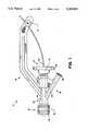
- FIG. 1illustrates a plan view of a Y-connector
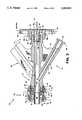
- FIG. 2illustrates a cross-sectional view of the Y-connector with the Touhy Borst cap removed;
- FIG. 3illustrates a cross-sectional view of a compression gasket for sealing along a guidewire in a Y-connector
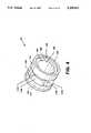
- FIG. 4illustrates a plan view of the compression gasket for a Y-connector, the present invention
- FIG. 5illustrates a top view of FIG. 4
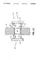
- FIG. 6illustrates a view taken along line 6--6 of FIG. 5;
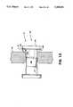
- FIG. 7illustrates a view taken along line 7--7 of FIG. 5;
- FIG. 8illustrates alignment of the compression gasket in the body of the Y-connector
- FIG. 9illustrates a cross-sectional view along line 9--9 of FIG. 10
- FIG. 10illustrates the sealing operation of a guidewire or medical device by the compressed compression gasket
- FIG. 11illustrates an exploded view of the guidewire clamp
- FIG. 12illustrates the clamp members engaging the side arm
- FIG. 13illustrates a guidewire or medical device frictionally engaged by the guidewire clamp.
- FIG. 1illustrates a front view of a Y-connector 10, the present invention with major components including a body 12, a Touhy Borst adapter 14, a rotating connector 16, a side port 18, a side arm 20, a guidewire clamp 21, and a compression gasket 22, all of which are described later in detail.
- Each componentis made of medical grade polymer materials.
- the body 12is the main structure for the Y-connector 10, and is an injection molded polycarbonate material with two lumens 24 and 26 configured in a Y orientation.
- the straight through part of the Y containing lumen 24is used for insertion of a circular medical device and is connected to the Touhy Borst adapter 14.
- the branch of the Y with the lumen 26contains a female luer connector 28 that can be used for a number of functions including an additional device, injection of flushing medium such as saline, or injection of contrast medium such as Renographin.
- One component of the Y-connector 10is a highly elastomeric compression gasket 22 which can be deformed under pressure and which has a through hole and which rests in a seat.
- the Touhy Borst cap 30is threaded and is used to apply pressure longitudinally on the compression gasket 22 deforming it inwardly around the inserted medical device, such as a guidewire, thus providing a seal. If no device is present, the hole collapses o itself and seals against any loss of fluids.
- the cap 30includes a large thumb wheel knob 32 for any movement, torquing and locking.
- the last componentis the rotating connector 16 which is used to connect the Y-connector 10 to a mating medical device, such as a guiding catheter
- the rotating connector 16contains a set of internal luer threads 80 to allow for locking of the Y-connector 10 onto another standard luer connection.
- rotationis provided about a quad O-ring and/or O-ring 36 as later described in detail in FIG. 3 so that the orientation of the Y-connector 10 can be changed relative to the mating medical device. This is important in positioning the flushing port relative to the patient.
- FIG. 2illustrates a cross-sectional view of the Y-connector 10 where all numerals correspond to those elements previously described.
- Lumen 24aligns longitudinally along the ergonormally sculptured main body portion 38 of the body 12.
- a radiused shoulder 40 with an adjoining flat donut like annular surface 41, an annular raised ring 42 and a lesser radiused shoulder 44extend from the main body 38, and aligns concentrically along the longitudinal center line of the lumen 24 at the left end of the body 12.
- the quad O-ring and/or O-ring 36frictionally engages the lesser radiused shoulder 44.
- a radiused shoulder 46 with adjoining threads 48extends from the opposing end of the body 12 to align concentrically along the longitudinal center line of the lumen 24.
- a radiused cavity 50aligns concentrically with the lesser radiused lumen 24 at the right end of the body 12 and intersects a recessed seat 49.
- An annular lip 51extends outwardly to the right from the recessed seat 49 to accommodate and engage the compression gasket 22 as later described in detail.
- the flexible plastic compression gasket 22aligns in the radiused cavity 50 in alignment with the recessed seat 49.
- Protrusions 52a-52n at the mount of the cavity 50act as keepers to capture the compression gasket 22 in the cavity 50.
- Lumen 26aligns within the extension body 54, and intersects and connects with the lumen 24.
- a cavity 56aligns with the lumen 2 in conjunction with the female luer connector 28 which aligns concentrically with the lumen 26.
- Protrusions 52a-52nalign at the outer circumference of the cavity 50 to also capture a snap ring 55 on the end of the tubular extension of cap 30 to keep the thumb wheel knob loosely coupled to the body 12.
- the Touhy Borst adapter 14aligns to and threadingly engages the main body 12 and includes a thumb wheel knob 32 and pluralities of gripping ribs 58a-58n and 60a-60n.
- An index tab or rib 61is included on the thumb wheel knob 32 of the cap 30.
- the cap 30includes internal threads 62 which align and mate with the threads 48 of the body 12.
- An annular cavity 64aligns concentrically along the center line of the cap 30 and is bounded by the internal threads 62 and by a concentric tubular extension 66.
- the tubular extension 66extends to the left from the thumb wheel knob 32, and includes a passage hole 68 with a flared opening 70.
- An annular lip 72extends from the tubular extension 66 to engage and accommodate the compression gasket 22.
- the rotating connector 16includes a round main body 73 with a plurality of external gripping ribs 74a-74n around its outer circumference.
- a male luer 76extends longitudinally from the main body 73 through a cavity 78.
- Raised threads 80line the cavity 78.
- the cavity 78, raised threads 80, a ramped cylinder section or male section 82, and surrounding main body 73form the male luer 76.
- the passageway 84 formed by the ramped cylinder section 82aligns concentrically with radiused cavities 86 and 88 and also with a rounded annular groove 90 which is located off-center to the right of the cavity 88.
- Cavity 88includes a flat donut like annular surface 92 adjacent to the radiused portion of the cavity 88.
- FIG. 3illustrates an assembled Y-connector 10 where all numerals correspond to those elements previously described.
- the Touhy Borst adapter 14is mated to the body 12 by engagement of internal threads 62 and 48.
- the tubular extension 66 of the Touhy Borst adapter 14is forced against the compression gasket 22 to cause the effective size of an internal hole in the compression gasket 22 to decrease in diameter to seal against a guidewire 93 as it is pressed against the recessed seat 49 and the annular lip 51 as later described in detail.
- the rotating connector 16snappingly engages the left end of the body 12.
- the cavity 86accommodates the radiused shoulder 44 of the body 12.
- the quad O-ring 36seals the rotating connecter 16 to the body 12 by sealing of its external surfaces against the lesser radiused shoulder 44 of the body 12, the donut like annular surface 41 of the body 12, the circumference of the cavity 88 of the rotating connector 16 and the flat donut like annular surface 92 of the rotating connector 16.
- the annular raised ring 42 of the body 12snappingly engages the rounded annular groove 90 of the rotating connector 16 to hold the body 12 and the rotating connector 16 in alignment and to maintain pressure against the quad O-ring and/or O-ring 36.
- FIG. 4illustrates a perspective view of the compression gasket 22, which can be made of silicon rubber or any other suitable material, compressible material which has a memory to return to its original geometrical shape when not compressed. Any other suitable materials can be utilized which exhibit compressible qualities and also exhibit memory to return to an original geometrical shape.
- the compression gasket 22includes a right edge 100 and a corresponding and opposed left edge 102.
- the outer circumferential wall 104is shaped in an hour glass configuration. The particular geometrical configuration of the outer circumferential wall 104 is that as illustrated in the Figure, but it is within the teachings of the present invention to vary the geometrical configuration as to the exact hour glass configuration.
- An inner hole 105aligns in the inner circumference 106 and includes an adjacent right annular rim 108, an adjacent a left annular rim 110, each of which is offset with respect to the right edge 100 and the left edge 102.
- the inner circumference 106frictionally engages against a guidewire, catheter or medical device as later described in detail.
- Optional vertical ribs 112a-112dare provided for supporting the right edge 100 with respect to the left edge 102. These vertical ribs cause the compression gasket 22 to internally close in a rhombic configuration about a medical device.
- Cavity 109is the space between the right annular ring 108 and the plane of the right edge 100.
- a similar opposing cavityis the space between the left annular ring 110 and the plane of the left edge 102.
- Cavities 109 and 111accommodate the annular lip 72 of the Touhy Borst adapter 14 and the annular lip 51 of the body 12 for compressional alignment of the compression gasket 22 with the lip members 72 and 51, respectively
- FIG. 5illustrates a side view of FIG. 4 where all numerals correspond to those elements previously described.
- Angled walls 114a and 16balign between the ribs 112a and 112d and the outer circumferential wall 104 as illustrated.
- Angled walls 114c-114d, 114e-114f and 114g-114halign between the ribs 112a-112d and about the circumferential wall 104 in a similar fashion.
- FIG. 6illustrates a sectional view taken along line 6--6 of FIG. 5 where all numerals correspond to those elements previously described.
- FIG. 7illustrates a sectional view along line 7--7 of FIG. 5 where all numerals correspond to those elements previously described.
- FIGS. 8-10illustrate the mode of operation where the compression gasket 22 is compressed from each side to seal about the guidewire 93.
- FIG. 8illustrates alignment of the compression gasket in the radiused cavity 50 where all numerals correspond to those elements previously described. Cavities 109 and 111 in the compression gasket 22 are in alignment for accommodation by the annular lips 72 and 51.
- the walls of the inner circumference 106are forced inwardly and downwardly toward the guidewire 93 as illustrated in FIG. 9.
- the walls of the inner circumference 106assume rhombic to square to round shape because of influence by the ribs 112a-112d during initial compression and during final compression assume a circular seal about the guidewire 93.
- FIG. 8illustrates alignment of the compression gasket in the radiused cavity 50 where all numerals correspond to those elements previously described.
- Cavities 109 and 111 in the compression gasket 22are in alignment for accommodation by the annular lips 72 and 51.
- angled walls 114a-114b and corresponding unillustrated angled walls 114c-114d, 114e-114f and 114g-114hfold inwardly towards their like mirror surfaces to aid in full inward movement of the inner circumference to cause sealing of the guidewire 93.
- a sufficient fluid sealis maintained while still maintaining the ability of the guidewire 93 to slide to and fro in sliding engagement.
- FIG. 11illustrates an exploded View of the guidewire clamp 21 which snappingly affixes a guidewire to the side arm support 20 as illustrated in FIG. 1 where all numerals correspond to those elements previously described.
- the guidewire clamp 21includes a left clamp member 120, each of which mutually engage each other. Flexible plastic discs 124 and 126 align over and about the left and right clamp members 120 and 122.
- a multi-radius cylindrical shaft member 128extends perpendicularly from a disc shaped head 130 and includes a centrally located wide recessed groove 132. Edges 128a and 128b are rounded or can be ramped to transition between the general large radius of the shaft 128 down to the wide groove 132.
- the right clamp member 122includes a cylindrical shaft member 134 extending perpendicularly from a disc shaped head 136.
- the flexible plastic discs 124 and 126include central holes 138 and 140 for engagement of the flexible plastic discs 124 and 136 over the cylindrical shaft member 128 and 130 as illustrated in FIG. 12.
- a cylindrical hole 142 in the shaft 128frictionally engages the cylindrical shaft 134 on the right clamp member shaft 122 to mate the left and right clamp members 120 and 122 through a beveled hole 144 in the side arm 20 as illustrated in FIG. 12.
- FIG. 12illustrates the left and right clamp members engaging the side arm 20 where all numerals correspond to those elements previously described.
- the flexible plastic discsare cemented to the heads 130 and 136, respectively.
- the wide groove 132frictionally and loosely engages the hole 144 to maintain the guidewire clamp 21 in a centrally aligned position with respect to the side arm 20 to allow a guidewire 93 to be readily positioned at either side of the side arm 20 and between either of the flexible plastic discs 124 and 126 and their respective heads.
- FIG. 13illustrates the mode of operation of the guidewire 93 or medical device frictionally engaged and secured between the side arm 20 and the flexible plastic disc 126 and adjacent disc shaped head 136 where the entire guidewire clamp 21 has been forcibly positioned to the left to effect the securement of the guidewire to the side arm 20.
- the hole 144disengages from alignment with the wide groove 132 of the shaft 128 by action of the ramp 128b against the beveled edges of the hole 144 to cause the wider radius portion of the cylindrical shaft member 128 to firmly engage the hole 144 for positive securement of the guidewire clamp 21 and guidewire with respect to the side arm 20.
Landscapes
- Health & Medical Sciences (AREA)
- Heart & Thoracic Surgery (AREA)
- Pulmonology (AREA)
- Engineering & Computer Science (AREA)
- Anesthesiology (AREA)
- Biomedical Technology (AREA)
- Hematology (AREA)
- Life Sciences & Earth Sciences (AREA)
- Animal Behavior & Ethology (AREA)
- General Health & Medical Sciences (AREA)
- Public Health (AREA)
- Veterinary Medicine (AREA)
- Infusion, Injection, And Reservoir Apparatuses (AREA)
Abstract
Description
Claims (2)
Priority Applications (5)
| Application Number | Priority Date | Filing Date | Title |
|---|---|---|---|
| US07/688,176US5205831A (en) | 1991-04-22 | 1991-04-22 | Compression gasket for y-connector |
| CA002060167ACA2060167A1 (en) | 1991-04-22 | 1992-01-28 | Compression gasket for y connector |
| EP92303273AEP0510851A1 (en) | 1991-04-22 | 1992-04-13 | Compression gasket for y-connector |
| US07/869,340US5338314A (en) | 1991-04-22 | 1992-04-16 | Rotating Y-connector |
| JP4101454AJPH05115559A (en) | 1991-04-22 | 1992-04-21 | Compression gasket for y-connector |
Applications Claiming Priority (1)
| Application Number | Priority Date | Filing Date | Title |
|---|---|---|---|
| US07/688,176US5205831A (en) | 1991-04-22 | 1991-04-22 | Compression gasket for y-connector |
Related Child Applications (1)
| Application Number | Title | Priority Date | Filing Date |
|---|---|---|---|
| US07/869,340Continuation-In-PartUS5338314A (en) | 1991-04-22 | 1992-04-16 | Rotating Y-connector |
Publications (1)
| Publication Number | Publication Date |
|---|---|
| US5205831Atrue US5205831A (en) | 1993-04-27 |
Family
ID=24763415
Family Applications (1)
| Application Number | Title | Priority Date | Filing Date |
|---|---|---|---|
| US07/688,176Expired - LifetimeUS5205831A (en) | 1991-04-22 | 1991-04-22 | Compression gasket for y-connector |
Country Status (4)
| Country | Link |
|---|---|
| US (1) | US5205831A (en) |
| EP (1) | EP0510851A1 (en) |
| JP (1) | JPH05115559A (en) |
| CA (1) | CA2060167A1 (en) |
Cited By (23)
| Publication number | Priority date | Publication date | Assignee | Title |
|---|---|---|---|---|
| US5324271A (en)* | 1993-06-04 | 1994-06-28 | Cordis Corporation | Double seal hemostasis connector |
| US5350364A (en)* | 1991-10-18 | 1994-09-27 | Ethicon, Inc. | Universal seal for trocar assembly |
| US5372584A (en)* | 1993-06-24 | 1994-12-13 | Ovamed Corporation | Hysterosalpingography and selective salpingography |
| US5391154A (en)* | 1993-08-30 | 1995-02-21 | United States Surgical Corporation | Trocar seal system |
| US5395364A (en)* | 1993-06-10 | 1995-03-07 | Symbiosis Corporation | Endoscopic instrument incorporating an elastomeric fluid seal |
| US5460615A (en)* | 1992-11-24 | 1995-10-24 | Storz; Karl | Trocar sleeve |
| US5591137A (en)* | 1995-07-14 | 1997-01-07 | Merit Medical Systems, Inc. | Hemostasis valve with locking seal |
| US5599327A (en)* | 1993-12-16 | 1997-02-04 | Terumo Kabushiki Kaisha | Connector |
| US5603702A (en)* | 1994-08-08 | 1997-02-18 | United States Surgical Corporation | Valve system for cannula assembly |
| US5693025A (en)* | 1995-07-14 | 1997-12-02 | Merit Medical Systems, Inc. | Adapter with hemostasis valve and rotatable connector |
| US20050090835A1 (en)* | 2003-07-31 | 2005-04-28 | Deal Stephen E. | Wire guide holder |
| US20050261661A1 (en)* | 2002-04-26 | 2005-11-24 | Mcfarlane Richard H | Floating seal assembly for a trocar |
| US20110208129A1 (en)* | 2010-02-22 | 2011-08-25 | Bonnette Michael J | Pressure actuated catheter seal and method for the same |
| US20130066328A1 (en)* | 2011-04-07 | 2013-03-14 | Jai Singh | General uterine manipulator and system |
| WO2013074936A1 (en)* | 2011-11-16 | 2013-05-23 | W.L. Gore & Associates, Inc. | Introducer sheath assembly having a locking dilator |
| US20130197536A1 (en)* | 2011-04-07 | 2013-08-01 | Jai Singh | General uterine manipulator and system |
| US20140100552A1 (en)* | 2012-10-02 | 2014-04-10 | The Queen's Medical Center | Vascular access systems having a guidewire anti-migration feature |
| US20160081717A1 (en)* | 2011-04-07 | 2016-03-24 | Jai Singh | General uterine manipulator and system |
| US9532837B2 (en) | 2012-04-20 | 2017-01-03 | Jiwan Steven Singh | Repositionable medical instrument support systems, devices, and methods |
| US10737086B2 (en) | 2017-03-13 | 2020-08-11 | Boston Scientific Limited | Hemostasis valves and methods for making and using hemostasis valves |
| US10953214B2 (en) | 2017-09-12 | 2021-03-23 | Boston Scientific Limited | Hemostasis valves and methods for making and using hemostasis valves |
| US10960501B2 (en) | 2017-03-13 | 2021-03-30 | Boston Scientific Limited | Hemostasis valves and methods for making and using hemostasis valves |
| US11291821B2 (en) | 2017-03-13 | 2022-04-05 | Boston Scientific Limited | Hemostasis valves and methods for making and using hemostasis valves |
Families Citing this family (25)
| Publication number | Priority date | Publication date | Assignee | Title |
|---|---|---|---|---|
| US5395342A (en) | 1990-07-26 | 1995-03-07 | Yoon; Inbae | Endoscopic portal |
| US5338314A (en)* | 1991-04-22 | 1994-08-16 | B. Braun Medical, Inc. | Rotating Y-connector |
| US5545142A (en) | 1991-10-18 | 1996-08-13 | Ethicon, Inc. | Seal members for surgical trocars |
| US5342315A (en)* | 1993-04-12 | 1994-08-30 | Ethicon, Inc. | Trocar seal/protector assemblies |
| US5529278A (en)* | 1993-11-19 | 1996-06-25 | Novoste Corporation | Fluid access and flow control valve |
| US5906595A (en)* | 1997-04-25 | 1999-05-25 | Ethicon Endo-Surgery, Inc. | Trocar having protector with flexible end and improved seal assembly |
| US8500792B2 (en) | 2003-09-03 | 2013-08-06 | Bolton Medical, Inc. | Dual capture device for stent graft delivery system and method for capturing a stent graft |
| US20070198078A1 (en) | 2003-09-03 | 2007-08-23 | Bolton Medical, Inc. | Delivery system and method for self-centering a Proximal end of a stent graft |
| US20080264102A1 (en) | 2004-02-23 | 2008-10-30 | Bolton Medical, Inc. | Sheath Capture Device for Stent Graft Delivery System and Method for Operating Same |
| US11259945B2 (en) | 2003-09-03 | 2022-03-01 | Bolton Medical, Inc. | Dual capture device for stent graft delivery system and method for capturing a stent graft |
| US7763063B2 (en) | 2003-09-03 | 2010-07-27 | Bolton Medical, Inc. | Self-aligning stent graft delivery system, kit, and method |
| US9198786B2 (en) | 2003-09-03 | 2015-12-01 | Bolton Medical, Inc. | Lumen repair device with capture structure |
| US11596537B2 (en) | 2003-09-03 | 2023-03-07 | Bolton Medical, Inc. | Delivery system and method for self-centering a proximal end of a stent graft |
| US8292943B2 (en) | 2003-09-03 | 2012-10-23 | Bolton Medical, Inc. | Stent graft with longitudinal support member |
| US20070161969A1 (en)* | 2004-01-29 | 2007-07-12 | Erik Andersen | Lock for a guide wire or an intravascular catheter |
| JP5236295B2 (en)* | 2005-02-10 | 2013-07-17 | クック メディカル テクノロジーズ エルエルシー | Wire guide holder with wire guide deflector |
| CN102076281B (en) | 2008-06-30 | 2014-11-05 | 波顿医疗公司 | Systems and methods for abdominal aortic aneurysm |
| EP3284447B1 (en) | 2009-03-13 | 2020-05-20 | Bolton Medical Inc. | System for deploying an endoluminal prosthesis at a surgical site |
| US8025642B2 (en)* | 2009-03-26 | 2011-09-27 | Tyco Health Group Lp | Powered variable seal diameter trocar employing a longitudinal displacement mechanism |
| JP5693080B2 (en)* | 2010-08-03 | 2015-04-01 | 日本コヴィディエン株式会社 | Catheter assist device and dialysis catheter set using the catheter assist device |
| EP2846743B1 (en) | 2012-04-12 | 2016-12-14 | Bolton Medical Inc. | Vascular prosthetic delivery device |
| US9439751B2 (en) | 2013-03-15 | 2016-09-13 | Bolton Medical, Inc. | Hemostasis valve and delivery systems |
| EP3146993B1 (en)* | 2013-03-15 | 2018-06-06 | Bolton Medical, Inc. | Hemostasis valve and delivery systems |
| EP4585192A3 (en) | 2020-06-24 | 2025-10-15 | Bolton Medical, Inc. | Anti-backspin component for vascular prosthesis delivery device |
| JP7699369B2 (en)* | 2021-05-21 | 2025-06-27 | 株式会社東海メディカルプロダクツ | Y-type connector |
Citations (8)
| Publication number | Priority date | Publication date | Assignee | Title |
|---|---|---|---|---|
| GB2063679A (en)* | 1979-11-29 | 1981-06-10 | Abbott Lab | Venipuncture device |
| US4419094A (en)* | 1981-06-08 | 1983-12-06 | The Kendall Company | Suprapubic catheter system |
| US4809679A (en)* | 1986-11-19 | 1989-03-07 | Olympus Optical Co., Ltd. | Forceps plug for endoscopes |
| US4857062A (en)* | 1988-03-09 | 1989-08-15 | Medical Parameters, Inc. | Catheter introducer valve |
| US4929235A (en)* | 1985-07-31 | 1990-05-29 | Universal Medical Instrument Corp. | Self-sealing percutaneous tube introducer |
| US4932633A (en)* | 1988-11-21 | 1990-06-12 | Schneider-Shiley (U.S.A.) Inc. | Hemostasis valve |
| US4978341A (en)* | 1988-04-07 | 1990-12-18 | Schneider Europe | Introducer valve for a catheter arrangement |
| US5009391A (en)* | 1988-05-02 | 1991-04-23 | The Kendall Company | Valve assembly |
Family Cites Families (4)
| Publication number | Priority date | Publication date | Assignee | Title |
|---|---|---|---|---|
| DE8619671U1 (en)* | 1986-07-22 | 1989-03-09 | Sterimed Gesellschaft für medizinischen Bedarf mbH, 6600 Saarbrücken | Coupling for connecting a medical tube, in particular a drain or a catheter, to another device |
| US4723550A (en)* | 1986-11-10 | 1988-02-09 | Cordis Corporation | Leakproof hemostasis valve with single valve member |
| US4874377A (en)* | 1988-05-26 | 1989-10-17 | Davis Newgard Revocable Family Living Trust | Self-occluding intravascular cannula assembly |
| DE3834600C1 (en)* | 1988-10-11 | 1989-12-21 | B. Braun Melsungen Ag, 3508 Melsungen, De | Puncturing and introduction device for elongate articles |
- 1991
- 1991-04-22USUS07/688,176patent/US5205831A/ennot_activeExpired - Lifetime
- 1992
- 1992-01-28CACA002060167Apatent/CA2060167A1/ennot_activeAbandoned
- 1992-04-13EPEP92303273Apatent/EP0510851A1/ennot_activeCeased
- 1992-04-21JPJP4101454Apatent/JPH05115559A/enactivePending
Patent Citations (8)
| Publication number | Priority date | Publication date | Assignee | Title |
|---|---|---|---|---|
| GB2063679A (en)* | 1979-11-29 | 1981-06-10 | Abbott Lab | Venipuncture device |
| US4419094A (en)* | 1981-06-08 | 1983-12-06 | The Kendall Company | Suprapubic catheter system |
| US4929235A (en)* | 1985-07-31 | 1990-05-29 | Universal Medical Instrument Corp. | Self-sealing percutaneous tube introducer |
| US4809679A (en)* | 1986-11-19 | 1989-03-07 | Olympus Optical Co., Ltd. | Forceps plug for endoscopes |
| US4857062A (en)* | 1988-03-09 | 1989-08-15 | Medical Parameters, Inc. | Catheter introducer valve |
| US4978341A (en)* | 1988-04-07 | 1990-12-18 | Schneider Europe | Introducer valve for a catheter arrangement |
| US5009391A (en)* | 1988-05-02 | 1991-04-23 | The Kendall Company | Valve assembly |
| US4932633A (en)* | 1988-11-21 | 1990-06-12 | Schneider-Shiley (U.S.A.) Inc. | Hemostasis valve |
Cited By (44)
| Publication number | Priority date | Publication date | Assignee | Title |
|---|---|---|---|---|
| US5350364A (en)* | 1991-10-18 | 1994-09-27 | Ethicon, Inc. | Universal seal for trocar assembly |
| US5460615A (en)* | 1992-11-24 | 1995-10-24 | Storz; Karl | Trocar sleeve |
| US5324271A (en)* | 1993-06-04 | 1994-06-28 | Cordis Corporation | Double seal hemostasis connector |
| US5395364A (en)* | 1993-06-10 | 1995-03-07 | Symbiosis Corporation | Endoscopic instrument incorporating an elastomeric fluid seal |
| US5372584A (en)* | 1993-06-24 | 1994-12-13 | Ovamed Corporation | Hysterosalpingography and selective salpingography |
| US5391154A (en)* | 1993-08-30 | 1995-02-21 | United States Surgical Corporation | Trocar seal system |
| US5599327A (en)* | 1993-12-16 | 1997-02-04 | Terumo Kabushiki Kaisha | Connector |
| US5895377A (en)* | 1994-08-08 | 1999-04-20 | United States Surgical Corporation | Valve system for cannula assembly |
| US5603702A (en)* | 1994-08-08 | 1997-02-18 | United States Surgical Corporation | Valve system for cannula assembly |
| US5591137A (en)* | 1995-07-14 | 1997-01-07 | Merit Medical Systems, Inc. | Hemostasis valve with locking seal |
| US5693025A (en)* | 1995-07-14 | 1997-12-02 | Merit Medical Systems, Inc. | Adapter with hemostasis valve and rotatable connector |
| US20050261661A1 (en)* | 2002-04-26 | 2005-11-24 | Mcfarlane Richard H | Floating seal assembly for a trocar |
| US7011314B2 (en) | 2002-04-26 | 2006-03-14 | Taut, Inc. | Floating seal assembly for a trocar |
| US20050090835A1 (en)* | 2003-07-31 | 2005-04-28 | Deal Stephen E. | Wire guide holder |
| US7637863B2 (en) | 2003-07-31 | 2009-12-29 | Wilson-Cook Medical Inc. | Wire guide holder |
| US8951229B2 (en) | 2010-02-22 | 2015-02-10 | Boston Scientific Limited | Pressure actuated catheter seal and method for the same |
| US20110208129A1 (en)* | 2010-02-22 | 2011-08-25 | Bonnette Michael J | Pressure actuated catheter seal and method for the same |
| US20160081717A1 (en)* | 2011-04-07 | 2016-03-24 | Jai Singh | General uterine manipulator and system |
| US9451985B2 (en) | 2011-04-07 | 2016-09-27 | Jiwan Steven Singh | General uterine manipulator and system |
| US9987042B2 (en)* | 2011-04-07 | 2018-06-05 | Jai Singh | General uterine manipulator and system |
| US9974567B2 (en) | 2011-04-07 | 2018-05-22 | Jiwan Steven Singh | General uterine manipulator and system |
| US20150012009A1 (en)* | 2011-04-07 | 2015-01-08 | Jai Singh | General uterine manipulator and system |
| US9101390B2 (en)* | 2011-04-07 | 2015-08-11 | Jai Singh | General uterine manipulator and system |
| US20130066328A1 (en)* | 2011-04-07 | 2013-03-14 | Jai Singh | General uterine manipulator and system |
| US10792072B2 (en) | 2011-04-07 | 2020-10-06 | Jai Singh | General uterine manipulator and system |
| US20130197536A1 (en)* | 2011-04-07 | 2013-08-01 | Jai Singh | General uterine manipulator and system |
| WO2013074936A1 (en)* | 2011-11-16 | 2013-05-23 | W.L. Gore & Associates, Inc. | Introducer sheath assembly having a locking dilator |
| CN103945785A (en)* | 2011-11-16 | 2014-07-23 | W.L.戈尔及同仁股份有限公司 | Introducer sheath assembly having a locking dilator |
| AU2012340313B2 (en)* | 2011-11-16 | 2015-07-09 | W. L. Gore & Associates, Inc. | Introducer sheath assembly having a locking dilator |
| US9561347B2 (en) | 2011-11-16 | 2017-02-07 | W. L. Gore & Associates, Inc. | Introducer sheath assembly having a locking dilator |
| US10744300B2 (en) | 2011-11-16 | 2020-08-18 | W. L. Gore & Associates, Inc. | Introducer sheath assembly having a locking dilator |
| CN103945785B (en)* | 2011-11-16 | 2017-04-05 | W.L.戈尔及同仁股份有限公司 | Guide sheath component with locking dilator |
| US10112030B2 (en) | 2011-11-16 | 2018-10-30 | W. L. Gore & Associates, Inc. | Introducer sheath assembly having a locking dilator |
| US11602615B2 (en) | 2011-11-16 | 2023-03-14 | W. L. Gore & Associates, Inc. | Introducer sheath assembly having a locking dilator |
| US9532837B2 (en) | 2012-04-20 | 2017-01-03 | Jiwan Steven Singh | Repositionable medical instrument support systems, devices, and methods |
| US10004569B2 (en) | 2012-04-20 | 2018-06-26 | Jiwan Steven Singh | Repositionable medical instrument support systems, devices, and methods |
| US8992480B2 (en)* | 2012-10-02 | 2015-03-31 | The Queen's Medical Center | Vascular access systems having a guidewire anti-migration feature |
| US20170072171A1 (en)* | 2012-10-02 | 2017-03-16 | The Queen's Medical Center | Vascular access systems having a guidewire anti-migration feature |
| US9504806B2 (en) | 2012-10-02 | 2016-11-29 | The Queen's Medical Center | Vascular access systems having a guidewire anti-migration feature |
| US20140100552A1 (en)* | 2012-10-02 | 2014-04-10 | The Queen's Medical Center | Vascular access systems having a guidewire anti-migration feature |
| US10737086B2 (en) | 2017-03-13 | 2020-08-11 | Boston Scientific Limited | Hemostasis valves and methods for making and using hemostasis valves |
| US10960501B2 (en) | 2017-03-13 | 2021-03-30 | Boston Scientific Limited | Hemostasis valves and methods for making and using hemostasis valves |
| US11291821B2 (en) | 2017-03-13 | 2022-04-05 | Boston Scientific Limited | Hemostasis valves and methods for making and using hemostasis valves |
| US10953214B2 (en) | 2017-09-12 | 2021-03-23 | Boston Scientific Limited | Hemostasis valves and methods for making and using hemostasis valves |
Also Published As
| Publication number | Publication date |
|---|---|
| JPH05115559A (en) | 1993-05-14 |
| EP0510851A1 (en) | 1992-10-28 |
| CA2060167A1 (en) | 1992-10-23 |
Similar Documents
| Publication | Publication Date | Title |
|---|---|---|
| US5205831A (en) | Compression gasket for y-connector | |
| US5338314A (en) | Rotating Y-connector | |
| US5279597A (en) | Catheter compression clamp | |
| US6402723B1 (en) | Inline hemostasis valve | |
| US4607868A (en) | Universal connector | |
| US4676530A (en) | Coupling assembly for use in fluid flow systems | |
| US4526572A (en) | Medical connector | |
| EP0733380B1 (en) | Luer-type connector | |
| US5989223A (en) | Rotatable medical valve closure | |
| US5944697A (en) | Percutaneous catheter introducer | |
| US5591137A (en) | Hemostasis valve with locking seal | |
| US5693025A (en) | Adapter with hemostasis valve and rotatable connector | |
| US4323065A (en) | Attachable connector for catheter | |
| US4387879A (en) | Self-sealing connector for use with plastic cannulas and vessel catheters | |
| US5599328A (en) | Split ring assembly for an airless rotatable connector | |
| CA2001558A1 (en) | Hemostasis valve | |
| EP1441801A1 (en) | H-shape duckbill hemostasis valve assembly including guide wire seal | |
| WO1998013083A1 (en) | Catheter sheath introducer with improved hemostasis valve | |
| EP0607343B1 (en) | Rotatable medical valve closure | |
| JP7645377B2 (en) | CATHETER ADAPTER SYSTEM FOR PROXIMALLY TEARABLE CATHETERS - Patent application | |
| CA1296961C (en) | Reverse taper spike connector |
Legal Events
| Date | Code | Title | Description |
|---|---|---|---|
| AS | Assignment | Owner name:ANGEION CORPORATION, 13000 HIGHWAY 55 PLYMOUTH, MN Free format text:ASSIGNMENT OF ASSIGNORS INTEREST.;ASSIGNORS:RYAN, WILLIAM P.;SAVAGE, STEVEN D.;REEL/FRAME:005677/0616 Effective date:19910418 | |
| AS | Assignment | Owner name:BURRON MEDICAL, INC., PENNSYLVANIA Free format text:ASSIGNMENT OF ASSIGNORS INTEREST.;ASSIGNOR:ANGEION CORPORATION;REEL/FRAME:006289/0604 Effective date:19920922 | |
| STCF | Information on status: patent grant | Free format text:PATENTED CASE | |
| AS | Assignment | Owner name:B. BRAUN MEDICAL INC., PENNSYLVANIA Free format text:CHANGE OF NAME;ASSIGNOR:BURRON MEDICAL INC.;REEL/FRAME:006537/0448 Effective date:19921001 | |
| CC | Certificate of correction | ||
| FEPP | Fee payment procedure | Free format text:PAYOR NUMBER ASSIGNED (ORIGINAL EVENT CODE: ASPN); ENTITY STATUS OF PATENT OWNER: LARGE ENTITY | |
| REMI | Maintenance fee reminder mailed | ||
| FEPP | Fee payment procedure | Free format text:PAT HLDR NO LONGER CLAIMS SMALL ENT STAT AS SMALL BUSINESS (ORIGINAL EVENT CODE: LSM2); ENTITY STATUS OF PATENT OWNER: LARGE ENTITY | |
| FPAY | Fee payment | Year of fee payment:4 | |
| SULP | Surcharge for late payment | ||
| FPAY | Fee payment | Year of fee payment:8 | |
| FPAY | Fee payment | Year of fee payment:12 |