US5205824A - Retractable syringe with a closed barrel - Google Patents
Retractable syringe with a closed barrelDownload PDFInfo
- Publication number
- US5205824A US5205824AUS07/714,431US71443191AUS5205824AUS 5205824 AUS5205824 AUS 5205824AUS 71443191 AUS71443191 AUS 71443191AUS 5205824 AUS5205824 AUS 5205824A
- Authority
- US
- United States
- Prior art keywords
- barrel
- needle holder
- piston
- needle
- shaft
- Prior art date
- Legal status (The legal status is an assumption and is not a legal conclusion. Google has not performed a legal analysis and makes no representation as to the accuracy of the status listed.)
- Expired - Fee Related
Links
- 239000012530fluidSubstances0.000claimsabstract8
- 238000007789sealingMethods0.000claimsabstract3
- 230000000087stabilizing effectEffects0.000claims2
- 230000000903blocking effectEffects0.000claims1
- 239000002131composite materialSubstances0.000claims1
- 230000000717retained effectEffects0.000claims1
Images


Classifications
- A—HUMAN NECESSITIES
- A61—MEDICAL OR VETERINARY SCIENCE; HYGIENE
- A61M—DEVICES FOR INTRODUCING MEDIA INTO, OR ONTO, THE BODY; DEVICES FOR TRANSDUCING BODY MEDIA OR FOR TAKING MEDIA FROM THE BODY; DEVICES FOR PRODUCING OR ENDING SLEEP OR STUPOR
- A61M5/00—Devices for bringing media into the body in a subcutaneous, intra-vascular or intramuscular way; Accessories therefor, e.g. filling or cleaning devices, arm-rests
- A61M5/178—Syringes
- A61M5/31—Details
- A61M5/32—Needles; Details of needles pertaining to their connection with syringe or hub; Accessories for bringing the needle into, or holding the needle on, the body; Devices for protection of needles
- A61M5/3205—Apparatus for removing or disposing of used needles or syringes, e.g. containers; Means for protection against accidental injuries from used needles
- A61M5/321—Means for protection against accidental injuries by used needles
- A61M5/3243—Means for protection against accidental injuries by used needles being axially-extensible, e.g. protective sleeves coaxially slidable on the syringe barrel
- A—HUMAN NECESSITIES
- A61—MEDICAL OR VETERINARY SCIENCE; HYGIENE
- A61M—DEVICES FOR INTRODUCING MEDIA INTO, OR ONTO, THE BODY; DEVICES FOR TRANSDUCING BODY MEDIA OR FOR TAKING MEDIA FROM THE BODY; DEVICES FOR PRODUCING OR ENDING SLEEP OR STUPOR
- A61M5/00—Devices for bringing media into the body in a subcutaneous, intra-vascular or intramuscular way; Accessories therefor, e.g. filling or cleaning devices, arm-rests
- A61M5/178—Syringes
- A61M5/31—Details
- A61M5/32—Needles; Details of needles pertaining to their connection with syringe or hub; Accessories for bringing the needle into, or holding the needle on, the body; Devices for protection of needles
- A61M5/3205—Apparatus for removing or disposing of used needles or syringes, e.g. containers; Means for protection against accidental injuries from used needles
- A61M5/321—Means for protection against accidental injuries by used needles
- A61M5/322—Retractable needles, i.e. disconnected from and withdrawn into the syringe barrel by the piston
- A—HUMAN NECESSITIES
- A61—MEDICAL OR VETERINARY SCIENCE; HYGIENE
- A61M—DEVICES FOR INTRODUCING MEDIA INTO, OR ONTO, THE BODY; DEVICES FOR TRANSDUCING BODY MEDIA OR FOR TAKING MEDIA FROM THE BODY; DEVICES FOR PRODUCING OR ENDING SLEEP OR STUPOR
- A61M5/00—Devices for bringing media into the body in a subcutaneous, intra-vascular or intramuscular way; Accessories therefor, e.g. filling or cleaning devices, arm-rests
- A61M5/178—Syringes
- A61M5/31—Details
- A61M5/32—Needles; Details of needles pertaining to their connection with syringe or hub; Accessories for bringing the needle into, or holding the needle on, the body; Devices for protection of needles
- A61M5/34—Constructions for connecting the needle, e.g. to syringe nozzle or needle hub
- A61M5/344—Constructions for connecting the needle, e.g. to syringe nozzle or needle hub using additional parts, e.g. clamping rings or collets
- A—HUMAN NECESSITIES
- A61—MEDICAL OR VETERINARY SCIENCE; HYGIENE
- A61M—DEVICES FOR INTRODUCING MEDIA INTO, OR ONTO, THE BODY; DEVICES FOR TRANSDUCING BODY MEDIA OR FOR TAKING MEDIA FROM THE BODY; DEVICES FOR PRODUCING OR ENDING SLEEP OR STUPOR
- A61M5/00—Devices for bringing media into the body in a subcutaneous, intra-vascular or intramuscular way; Accessories therefor, e.g. filling or cleaning devices, arm-rests
- A61M5/178—Syringes
- A61M5/31—Details
- A61M2005/3103—Leak prevention means for distal end of syringes, i.e. syringe end for mounting a needle
- A61M2005/3106—Plugs for syringes without needle
- A—HUMAN NECESSITIES
- A61—MEDICAL OR VETERINARY SCIENCE; HYGIENE
- A61M—DEVICES FOR INTRODUCING MEDIA INTO, OR ONTO, THE BODY; DEVICES FOR TRANSDUCING BODY MEDIA OR FOR TAKING MEDIA FROM THE BODY; DEVICES FOR PRODUCING OR ENDING SLEEP OR STUPOR
- A61M5/00—Devices for bringing media into the body in a subcutaneous, intra-vascular or intramuscular way; Accessories therefor, e.g. filling or cleaning devices, arm-rests
- A61M5/178—Syringes
- A61M5/31—Details
- A61M5/32—Needles; Details of needles pertaining to their connection with syringe or hub; Accessories for bringing the needle into, or holding the needle on, the body; Devices for protection of needles
- A61M5/3205—Apparatus for removing or disposing of used needles or syringes, e.g. containers; Means for protection against accidental injuries from used needles
- A61M2005/3206—Needle or needle hub disconnecting devices forming part of or being attached to the hub or syringe body
- A—HUMAN NECESSITIES
- A61—MEDICAL OR VETERINARY SCIENCE; HYGIENE
- A61M—DEVICES FOR INTRODUCING MEDIA INTO, OR ONTO, THE BODY; DEVICES FOR TRANSDUCING BODY MEDIA OR FOR TAKING MEDIA FROM THE BODY; DEVICES FOR PRODUCING OR ENDING SLEEP OR STUPOR
- A61M5/00—Devices for bringing media into the body in a subcutaneous, intra-vascular or intramuscular way; Accessories therefor, e.g. filling or cleaning devices, arm-rests
- A61M5/178—Syringes
- A61M5/31—Details
- A61M5/32—Needles; Details of needles pertaining to their connection with syringe or hub; Accessories for bringing the needle into, or holding the needle on, the body; Devices for protection of needles
- A61M5/3205—Apparatus for removing or disposing of used needles or syringes, e.g. containers; Means for protection against accidental injuries from used needles
- A61M5/321—Means for protection against accidental injuries by used needles
- A61M5/322—Retractable needles, i.e. disconnected from and withdrawn into the syringe barrel by the piston
- A61M5/3221—Constructional features thereof, e.g. to improve manipulation or functioning
- A61M2005/3231—Proximal end of needle captured or embedded inside piston head, e.g. by friction or hooks
Definitions
- the present inventionprovides a retractable syringe in which the needle holder is releasably positioned and secured in the forward open end of the syringe barrel.
- the piston and the shaftoperate as a plunger in the syringe, to draw in and dispense liquids in the normal manner.
- the plungeris forced in with slightly greater force than in normal operation to cause the piston to engage the needle holder.
- the plungeris then pulled rearwardly pulling the piston and the joined needle holder, releasing the releasable connection to the forward open end of the barrel.
- the syringethus ends up with the piston blocking and sealing one end of the barrel, and the shaft sealing and locking the other end of the barrel, with the shaft projecting into contact the needle or needle holder in the barrel, holding the needle from movement.
- the entire packagemay then be disposed of in a safe and simple manner.
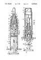
- FIG. 1is a side elevation view of the retractable syringe, with portions cut away;
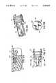
- FIG. 2is an enlarged sectional view taken on line 2--2 of FIG. 1;
- FIG. 4is an enlarged sectional view taken on line 4--4 of FIG. 1;
- FIG. 5is an enlarged sectional view taken on line 5--5 of FIG. 1;
- FIG. 6is a perspective view of the piston end of the plunger
- FIG. 7is a perspective view of the needle carrier
- FIG. 9is a view similar to FIG. 5, with the piston latched on the needle carrier;
- FIG. 10is a similar view, with the piston and shaft withdrawn and the needle carrier and needle retracted into the syringe body;
- FIG. 11is a similar view, with the piston shaft broken off and the piston and needle carrier locked in the retracted position;
- FIG. 12is a similar view, with the shaft inserted and locked in the opposite end of the body to enclose the needle;
- FIG. 13is a sectional view taken on line 13--13 of FIG. 12;
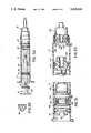
- FIG. 14is a view similar to FIG. 5, with a modified alignment means between the piston and the needle holder, and illustrating ejection of fluid;
- FIG. 15is a view similar to FIG. 14, with the piston and needle holder interlocked;
- FIG. 17is an enlargement of a portion of FIG. 16, with a detail of the piston ring;
- FIG. 18is a side elevation view of the structure of FIG. 16, illustrating the use of the piston ring as a capacity indicator;
- FIG. 19is a side elevation view of a modified form of the piston
- FIG. 20is a view similar to FIG. 11, showing the piston retained in the syringe with the needle holder attached;
- FIG. 21is an end view of the syringe, illustrating the orientation of the plunger with the syringe body
- FIG. 22is a side elevation view, partially sectioned, illustrating a pre-use sheath secured over the needle
- FIG. 23is a similar view illustrating an alternative needle sheath arrangement
- FIG. 24is a sectional view taken on line 24--24 of FIG. 23;
- FIG. 25is a sectional view similar to FIG. 17, with a different "O" ring;
- FIG. 26is a perspective view similar to FIG. 6 with a different frangible section
- FIG. 27is a side elevation view similar to FIG. 19 with a different frangible section
- FIG. 28is a sectional view taken on line 28--28 of FIG. 27;
- FIG. 30is a side elevation view similar to FIG. 1 with a modified barrel and shaft stabilization construction
- FIG. 31is a similar view to FIGS. 11 and 31, with the piston and needle holder interconnecting structure being modified in a new embodiment
- FIG. 32is a side elevation sectional view similar to that of FIG. 5, illustrating the modified embodiment in FIG. 31.
- FIG. 1there is illustrated a retractable syringe 10 having a hollow syringe barrel 12.
- This barrel and other suitable parts of the syringeare made of a plastic material such as polypropylene.
- the syringe barrel 12has a forward end 15 and a rearward open end 17. Releasably positioned in the forward end is the needle holder assembly 18.
- a movable plungerhas a piston 24 with an O-ring seal that is connected to a shaft 14 that extends out the open end 17 of the barrel 12.
- a thumb driven actuator surface 16 at the end of the shaft 14coacts with finger grip 26 on the open end of the barrel 17 to push and pull the piston 24 in the barrel in the manner of operating the syringe.
- the piston 24has means or grasping the end 32 of the needle holder 18, which will be described in more detail hereinafter, and pulls the needle holder rearwardly to the point that the needle holder 18, the needle housing 20 and the needle 22 are all moved into a retracted position within the syringe barrel as illustrated in FIG. 11. With the needle holder in this position, the needle 22 is entirely enclosed within the volume of the barrel 12. The shaft 14 is then broken off from the piston 24, and the free broken end of the shaft 14 is then inserted through the forward open end 15 of the barrel 12. The shaft thus functions to close off the open forward end of the barrel with the piston closing off the rearward open end of the barrel, securing and enclosing the retracted needle within the barrel. Both ends of the barrel are thus closed and are sealed by the piston at one end and the shaft at the other end, so that the needle and the remaining fluid are both sealed within the barrel. The barrel is now ready for disposal.
- the piston and joined needle holdercan be locked in the barrel, or are prevented from being pulled out the rear open end of the barrel.
- a separate “C” clip lock meansprevents the needle holder from being moved from the releasable connection until released by the syringe user. Also the space between the barrel and the needle holder is sealed by an "O" ring seal.
- the piston 24has an outer circumferential groove 49 for receiving an O-ring 48.
- O-ring 48may be made of any suitable material and functions as a movable seal between the piston and the inner surface of the barrel 12.
- the "O" ringis preferably made of rubber. It has been discovered that rubber functions as a better seal against the plastic barrel, than plastic against plastic.
- the groove 49has sufficient width and depth to prevent the O-ring 48 from rolling over or out of groove 49.
- the O-ring 48functions as a wiper for wiping inner surfaces of the barrel along with moving the fluid by virtue of the piston action both into and out of the hollow syringe barrel 12.
- the piston 24has an axially centered recess 56 that receives and co-acts, in one embodiment of the syringe, with a nut type alignment 94, see FIGS. 14, 15 and 16, as will be described in more detail hereinafter.
- the front end of the piston 24has a pair of arcuate members 30 and 31 each of which form fingers with internal shoulders 33 that co-act to slide over the rear cam surface 27 on the rear end of the needle holder 18.
- the fingers 30 and 31, see FIG. 3have sufficient resilient biasing to cause the fingers to be cammed outwardly by the cam surface 27 to snap in, fit in or grip into the groove 32 of the needle holder 18.
- the fingers 30 and 31are only arcuate sections, and do not enclose the entire circumference of groove 32, for reasons that will be explained in more detail hereinafter.
- Lath member 90is connected to the side edge of lath member 86 that is in turn connected to lath member 88 that is connected to lath member 87 that has a side projecting lath member 89. It may be understood that this entire composition shaft structure 40 provides lateral rigidity against bending force moving the piston 24. This configuration provides an open center space in the syringe barrel 12 for receiving the end of the needle and needle housing 20 when the shaft 24 is inserted into the open end of the barrel 15 as illustrated in FIG. 12. Collars or discs 34 and 42 are molded into the shaft 14 and extend outwardly, see FIGS. 1 and 2, to provide centralized positioning of the shaft in the barrel 12.
- the frangible sectionscomprise lath type members 37 and 38, see FIGS. 1, 4, 5 and 6, that are radially aligned and have a relatively thin cross-section. These lath members may be broken when subjected to lateral bending forces in a given direction. These lateral bending forces are resisted by the other cross sectional configuration of the lath member 14 as previously described and as illustrated in FIG. 2.
- the lath members 37 and 38are also scored at 39 on either side or both sides of each member, which further facilitates the breaking of the frangible sections 37 and 38.
- the frangible membersinterconnect the remainder of the shaft with the rear side of the piston 24, thus allowing shaft 24 to be broken at a point adjacent to the piston.
- a modified frangible sectionis substituted for the lath members 37 and 38, primarily to provide added lateral stability.
- the lath members 138 and 140corresponding respectively to lath members 37 and 38, and are made with an "L" shaped cross-section.
- the bottom of the "L" shape for each sectionis integral with the adjoining lath members 86 and 87.
- Each of the "L" shaped membersare scored at 139 and 141 on all sides except the outer edges 151, to facilitate breakage of the shaft in the manner previously described.
- the rear open end 17 of the barrel 12has a V-shaped inner surface 37 that narrows the diameter of the opening.
- the respective collars 34 and 42have a smaller diameter than the inner diameter of ring surface 36, and thus pass freely therethrough.
- the piston 24has larger diameter rims 57 and 59 that restrain the piston from movement out of the open end 17 and through the inward V-shaped ring surface 36.
- the diameter of rim 57is slightly larger than the inner diameter of ring surface 36 and rim 57 has an angled, canted outer edge surface that allows rim 57 to contact and be cammed through the V-shaped ring 36.
- the outer diameter and shape of piston rim 59is relatively square and thus the outer side edges of rim 59 contact the side surfaces of the V-shaped projection 36 and prevents passage through opening 17. This effectively locks the piston into the open end 17 of the rear portion of the barrel 12.
- the piston 24may be initially inserted into the barrel 12 by pushing the piston through the restricted neck 36 in the open end 17 of the barrel. This is accomplished by exerting considerable longitudinal force on the piston by the shaft 24. This force is sufficient to move the piston and the outer rim portions 57 and 59 through the neck 36. However, when the neck 36 is snapped into the slot 65, this essentially locks the piston in the secured and sealed position where it is held against the normal application of forces against the piston that would occur in normal operation of the syringe. While the force required to move the piston from this locked position, as for example that force required to insert the piston through the neck 39 in initial installation, would normally not occur in the operation of the syringe.
- the pistonhas a different shaped rim member 92 that does not have the canted outer end surface and also has an outside diameter generally corresponding to the diameter of rim 59. So in rearward movement of the piston, the outer edge surface of rim 92 contacts the side of the inner shape ring 36, see FIG. 20, in the manner that prevents movement of the ring 92 of the piston out of the open end 17 and through the inner ring-shaped projection 36. Accordingly, ring projection 36 does not snap into slot 65, and the piston is not locked into the open rear end of the barrel in this embodiment. Rather, the piston is pulled to the end of the open end of the barrel, and it remains in that position. It may be understood that when the shaft 14 is broken off, O-ring 88 exerts sufficient outward pressure against the inner surface of the syringe barrel 12 to hold the piston 24 against longitudinal movement within the barrel, and to provide a seal against fluid movement.
- the needle 22is held by a needle housing 20 in the known manner.
- the needle holder 18has an internal threaded recess in its forward end for receiving the standard end 64 of a needle housing 20.
- the needle housing 20is threaded into the threads 60 and is held in position.
- the wide space between the thread bights in threads 60allows the needle holder 18 to hold or interconnected different, standard needle housing designs.
- Needle holder 18has a conical forward outer end surface with a first circumferential groove 68.
- Groove 68has a forward canted cam surface 82 and a rear abutment section 28 that forms one side of an O-ring recess for holding O-ring 50 in position.
- the O-ring 50provides a fluid seal in opening end 15. Again, preferably the O-ring is made of rubber. Also, the O-ring seal maintains a fluid seal around the needle holder end during slight rearward movements of the needle holder.
- the longitudinal pressure on the shaftmay be increased and continued causing the fingers 31 to cam over the end surface 32 of the rear end of the needle holder 18, and thus hook or grasp into the circumferential slot 32.
- the fingers 30 in grasping the needle holder 18,secures the needle holder to the piston 24. So when the piston 24 is pulled rearwardly, the piston pulls the needle holder with it, causing the needle holder to cam open the lips 58 of the open end 15 of the barrel. This pulls the needle holder 20 and needle 22 into the enclosed position as illustrated in FIG. 11.
- the increased force required to cause the fingers of the piston to grasp the needle holderis of such magnitude that the syringe user has to intentionally and thus knowingly increase the force. So accidentally joining the piston to the needle holder doesn't normally occur.
- the plungeri.e. the piston is aligned through rotating the thumb pressing member 16, which aligns the fingers 30 and 31 in the groove so that they do not shield the opening of passage 52.
- Only a single passageway 52is shown to conduct fluid from volume 48 to passageway 72. It may be understood that there may be more than one of such passageways through the end of the needle holder, but the preferred embodiment has only a single passageway as it has been found that a single passageway is better capable of conducting fluid and air from volume 48 out through passageway 72, and not trapping or retaining an air bubble in the upper end of the volume 48, in operation of the syringe.
- the barrel 12has a straight inner cylindrical surface without the inward V projection 36 of FIG. 1.
- the barrelis dimpled 47 by a dimple tool to provide an inward projection 45.
- the material from which the barrel 12 is madeis of a very tough, durable, and yet slightly ductile, resilient material. Accordingly a known dimple machine may strike the side of the barrel 12, impacting the side of the barrel and causing a dent or dimple 47 that results in an inward projection or dimple projection 45.
- FIG. 31the outer configuration of the rear ring member 157 of the piston 24, which has the configuration as illustrated in FIG.
- Ring or disc member 45is a second collar or disc member that it secured to the shaft at a location closer to the end of the shaft, and which ring 45 functions to provide added stability against lateral movement by the shaft in its longitudinal movement in the volume 46 of the barrel 42.
- a toolsuch as a male key driver fits into and coacts with the shape of recess 92 in the rear end of the needle holder 18. This aids in moving the forward end of the needle holder through the lips 58 and also allows needle holder 18 to be rotated to the point that key 54 fits into slot 67 of the needle holder 18.
- a nut-shaped end 94projects outwardly from the rear end of needle holder 18.
- a suitable wrenchthen fits over nut 94 and is rotated thereby, which aids in pushing the needle holder 18 into position and also to rotate and orient slot 67 with the key 54.
- end 54substantially fills the volume 56 in the end of piston 24, reducing the amount of fluid left in volume 46 of the barrel 12 after the fluid has been ejected through the needle 22, and also after the piston has been latched to the needle holder to pull the needle holder and needle into the barrel 12. In pulling the needle holder and needle into the barrel 12, it is desirable to eject as much fluid as possible from the syringe volume.
- the O-ring 48 in piston 24comprises a split O-ring, see FIGS. 16 and 17.
- the O-ring slot 121which preferably is made of O-ring rubber, is larger than the radial slot 49 in FIG. 4 and the O-ring 120 has a wider, rectangular cross-sectional shape.
- the outer circumferential surface of O-ring 126has a groove 122. This groove provides a pair of outer contacting surfaces 124 and 126 that provide a separate spaced wiping surface combination for wiping and sealing fluid moved by piston 24.
- a slanted edge surface 128 on one endaids in restricting roll-up of the rearward edge of the O-ring 120, when pulling a vacuum in volume 46.
- the circumferential aperture 122has a defined edge 123 that co-acts with calibrated metering lines 130 on the barrel 12 to allow measurement of fluid in the barrel 12.
- the O-ring 136is substituted for O-ring 120 on piston 24.
- O-ring 136provides the same operational advantages as O-ring 126 and is symmetrical, simplifying installation.
- the side edges of the O-ring 120 as well as O-ring 48are such that it restricts rolling movement of the O-ring 48 with movement of the piston 24.
- the advantage of the split O-ring 120 in FIGS. 16 and 17is that it further restricts such rolling movement, and also provides a double seal along with providing a relatively visible line on which to calibrate the fluid in the barrel relative to the position of piston 24.
- the wider contact surface of the split O-ring 126provides a wider contact surface with the barrel. This increases the holding force on the piston when the piston is in the retracted position and after the shaft has been broken, and the piston is not locked into the open end 17 of the barrel. Further this wider and larger surface contact also holds the piston against side movement and thus creates a longer force holding the needle against dropping by gravity when the piston and needle are retracted in the barrel and the shaft has been broken.
- the two collars or disc members 34 and 42are thus caused to lock the shaft into the neck or lips 58 of the open barrel end.
- the disc 34has a solid construction, see FIG. 2, and has a canted surface. This canted surface when contacting lips 58, allows the disc 34 to pass through the opening. This then places the lips 58 in a locked position in space 44, and provides a sealing surface contact with the sides of discs 34 and 42. Further, since both discs are solid a double seal occurs between disc 34 and disc 42.
- a needle cover or syringe cover 100is also encompassed within the inventor's invention.
- This coverhas a closed end 102 with an open end 103 having an internal configuration for fitting over and against the conical outer surface of the needle holder 18, and has a radial end surface at ring shoulder 106 that abuts against the forward surface of the lip 58 of the barrel 12. If an impact occurs against the end of the needle cover or sheath 100, this force is transmitted directly against the forward end of the barrel 12 and does not exert a rearward force against the needle holder 18, that could otherwise cause the needle holder to be released by the lip 58.
- a third groove 110is provided in the end of the needle holder, see FIGS. 23 and 24.
- This groove 110receives a snap, half ring or C-clip 108 that is shaped to fit into the groove 110 and be retained in the position by its circular configuration that is slightly larger in circumference than one-half of the circumference of the groove.
- the snap ringhas an open section that allows the ring to be inserted laterally into groove 110. In this position, the needle housing 118 is restrained from any rearward movement that would cause the housing 118 to cam through the lip latching means 58 at the end 17 of the barrel 12. This allows a standard needle sheath 114 to be mounted onto the needle holder 120.
- the userusually inserts the syringe and makes the injection.
- the syringe userpushes the plunger in with the syringe user's right thumb
- the syringe usernormally grasps the side of the barrel with their left hand, steadying the syringe as it is pulled from the person who received the injected fluid.
- the syringe usercan just push the plunger forward with force sufficient to engage the plunger and the needle holder.
- the userWith the user's left hand on the barrel, the user merely moves their thumb forward and in flipping the thumb against the nob, flips the C-clip out of the slot or groove.
- the needle holderis now released from the C-clip lock, and may be pulled wit rearward force on the piston, to the retracted position in the barrel.
- the barrel 12 and the syringe 10receives the needle housing 18 through the opening in the rear end 17 of the barrel 12.
- Any suitable toolpushes the needle housing 18 through the lip 58, which causes the lip to be resiliently biased into the outer groove of the housing 18, thus releasably holding the housing 18 in position.
- a suitable wrenchwhich may also be the driver for inserting the housing 18 into the barrel and into position, is used to rotate the housing 18 to the correct orientation as set by the key 54 and the slot 68.
- the shaft 14 and piston 24are then rotated by the finger pressure end 16 to correct alignment with the finger actuating flanges 26, to align the hole passage 52 with fingers 30 and 31.
- the shaft 14thus drives the piston 48 into the cylinder 12 to a location immediately adjacent the rear end 27 of the housing 18.
- the syringe piston 24is then moved to draw fluid through the needle 22 into the volume 46 of the barrel 12.
- the plungeris then pushed forward by the finger thumb pressure end 16 and shaft 14, with fluid being exited through the needle 22, to remove air from the piston volume 46.
- the fluidthen flows through passage 52 to the inner passage 72 and out the needle 22. Fluid is then injected in the normal operation of the syringe with the piston 24 moving the measured amount as determined by the calibration units on the barrel, see FIG. 18.
- any remaining fluidis further ejected by movement of the piston 24 into contact with the end 32 of the needle housing 18, with the fingers 30 and 31 engaging the end of the needle housing 18.
- the plunger 24is then pulled by pulling on the shaft 14, in the rearward direction. This force is sufficient to cause the lips 58 to be cammed out of the slot 68, thus releasing the needle housing 18 to be pulled through the opening in end 15 to the internal retained position where the needle is totally enclosed within the barrel 12.
- the pistonis pulled into contact with the end of the restricted diameter of the rear end of the barrel 12, see FIG. 11, or in the embodiment in FIG. 10, greater force is exerted onto the shaft 14 and piston 24, pulling it into the locked position of Figure 10.
- the weakened portions 37 and 38 of the shaft member 14are at the end opening of the syringe barrel 12.
- the shaft 14is then bent laterally breaking the shaft connection to the piston 24, thus breaking members 37 and 38 which may be along the score lines 39.
- the shaft 14is then free from the piston 24, and is inserted into the now open end 17 of the barrel 12, see FIG. 12.
- the shaftis inserted directly into the barrel with the needle 22 being positioned in the center space of the composite shaft structure, see FIG. 13.
- a standard syringe sheathis removed from the end of the syringe, allowing the syringe to be used in the normal manner. Then before retraction, the lock clip is removed from the forward end of the syringe, and the syringe is then retracted in the manner previously described.
- piston 24 and needle holder 18 as previously illustrated in FIGS. 1 and 5are modified to new piston 142 and new needle holder 152.
- the new piston 142does not have the grasping fingers, but instead has a projection having an outer frusto-conical end 146 with an inner forward outer circumferential slot 144. This end projection cooperates with the respective fingers 148 and 150 on the rearward end of the needle holder 152, that correspond with the fingers 30 and 31 previously described relative to FIG. 1.
- the fingershave the same shape as illustrated in FIG.
- the inner rearward surface 162 of the needle holder 152provides a cavity for Collection of the fluid in the syringe, which fluid passes out through opening 166 to the needle 22.
- the needle holderWhen the C clip 108 is in position, the needle holder cannot be moved rearwardly into the barrel, either inadvertently or intentionally.
- the usermay force the piston by pressing on end 116 with sufficient force that it causes the fingers 30 or 31 to pass into the rear slot 53 and then secure the piston and needle holder together. This could render the syringe inoperable, other than to pull the needle holder out of the end of the barrel and secure the entire syringe into the inoperable condition as previously described.
- the operatorWith the C clip in position, the operator merely exerts a larger pulling force on end member 16, pulling the plunger sufficiently to cause the fingers 30 and 31 to release their grip on the groove 52, separating the piston from the needle holder.
Landscapes
- Health & Medical Sciences (AREA)
- Engineering & Computer Science (AREA)
- Heart & Thoracic Surgery (AREA)
- Vascular Medicine (AREA)
- Anesthesiology (AREA)
- Biomedical Technology (AREA)
- Hematology (AREA)
- Life Sciences & Earth Sciences (AREA)
- Animal Behavior & Ethology (AREA)
- General Health & Medical Sciences (AREA)
- Public Health (AREA)
- Veterinary Medicine (AREA)
- Environmental & Geological Engineering (AREA)
- Infusion, Injection, And Reservoir Apparatuses (AREA)
Abstract
Description
Claims (42)
Priority Applications (19)
| Application Number | Priority Date | Filing Date | Title |
|---|---|---|---|
| US07/714,431US5205824A (en) | 1991-06-13 | 1991-06-13 | Retractable syringe with a closed barrel |
| CA002111208ACA2111208A1 (en) | 1991-06-13 | 1992-06-12 | Syringe with retractable needle and closed barrel |
| JP50109893AJP3559557B2 (en) | 1991-06-13 | 1992-06-12 | Retractable syringe with closed body |
| AU22395/92AAU655559B2 (en) | 1991-06-13 | 1992-06-12 | Retractable syringe with a closed barrel |
| BR9206138ABR9206138A (en) | 1991-06-13 | 1992-06-12 | Syringe with retractable needle and closed cylindrical body |
| KR1019930703874AKR100245533B1 (en) | 1991-06-13 | 1992-06-12 | Telescopic syringe with closed barrel |
| EP92914438AEP0593581A1 (en) | 1991-06-13 | 1992-06-12 | Syringe with retractable needle and closed barrel |
| SG9603083ASG86295A1 (en) | 1991-06-13 | 1992-06-12 | Retractable syringe with a closed barrel |
| PCT/US1992/005116WO1992022339A1 (en) | 1991-06-13 | 1992-06-12 | Syringe with retractable needle and closed barrel |
| US07/939,449US5308329A (en) | 1991-06-13 | 1992-09-02 | Retractable syringe with a closed barrel |
| EP93921295AEP0686050A1 (en) | 1991-06-13 | 1993-08-31 | Retractable syringe with a closed barrel |
| BR9306987ABR9306987A (en) | 1991-06-13 | 1993-08-31 | Retractable syringe |
| PCT/US1993/008256WO1994005356A1 (en) | 1991-06-13 | 1993-08-31 | Retractable syringe with a closed barrel |
| JP6507432AJPH08502674A (en) | 1991-06-13 | 1993-08-31 | Retractable syringe with closed barrel |
| SG1996003085ASG50512A1 (en) | 1991-06-13 | 1993-08-31 | Magnetically permeable electrostatic shield |
| AU48443/93AAU681859B2 (en) | 1991-06-13 | 1993-08-31 | Retractable syringe with a closed barrel |
| CA002142731ACA2142731A1 (en) | 1991-06-13 | 1993-08-31 | Retractable syringe with a closed barrel |
| US08/167,557US5401246A (en) | 1991-06-13 | 1993-12-14 | Retractable syringe with a closed barrel |
| JP2003313021AJP2004130120A (en) | 1991-06-13 | 2003-09-04 | Housing type syringe with closed body |
Applications Claiming Priority (1)
| Application Number | Priority Date | Filing Date | Title |
|---|---|---|---|
| US07/714,431US5205824A (en) | 1991-06-13 | 1991-06-13 | Retractable syringe with a closed barrel |
Related Child Applications (1)
| Application Number | Title | Priority Date | Filing Date |
|---|---|---|---|
| US07/939,449Continuation-In-PartUS5308329A (en) | 1991-06-13 | 1992-09-02 | Retractable syringe with a closed barrel |
Publications (1)
| Publication Number | Publication Date |
|---|---|
| US5205824Atrue US5205824A (en) | 1993-04-27 |
Family
ID=24870010
Family Applications (2)
| Application Number | Title | Priority Date | Filing Date |
|---|---|---|---|
| US07/714,431Expired - Fee RelatedUS5205824A (en) | 1991-06-13 | 1991-06-13 | Retractable syringe with a closed barrel |
| US07/939,449Expired - LifetimeUS5308329A (en) | 1991-06-13 | 1992-09-02 | Retractable syringe with a closed barrel |
Family Applications After (1)
| Application Number | Title | Priority Date | Filing Date |
|---|---|---|---|
| US07/939,449Expired - LifetimeUS5308329A (en) | 1991-06-13 | 1992-09-02 | Retractable syringe with a closed barrel |
Country Status (9)
| Country | Link |
|---|---|
| US (2) | US5205824A (en) |
| EP (2) | EP0593581A1 (en) |
| JP (3) | JP3559557B2 (en) |
| KR (1) | KR100245533B1 (en) |
| AU (2) | AU655559B2 (en) |
| BR (2) | BR9206138A (en) |
| CA (2) | CA2111208A1 (en) |
| SG (2) | SG86295A1 (en) |
| WO (2) | WO1992022339A1 (en) |
Cited By (47)
| Publication number | Priority date | Publication date | Assignee | Title |
|---|---|---|---|---|
| US5328484A (en)* | 1992-08-12 | 1994-07-12 | Brice Somers | Non-reusable syringe for medical purposes |
| US5336198A (en)* | 1993-02-01 | 1994-08-09 | Innova Development Corp. | Hypodermic syringe with needle retraction feature |
| US5338304A (en)* | 1992-06-15 | 1994-08-16 | Adventec, Inc. | Needle protected syringe |
| US5346474A (en)* | 1991-11-06 | 1994-09-13 | Design & Engineering Associates | Disposable safety syringe |
| US5431630A (en)* | 1993-09-07 | 1995-07-11 | Surgic-Acid, Inc. | Needle guard and nonreusable syringe |
| US5480385A (en)* | 1995-01-10 | 1996-01-02 | Specialized Health Products, Inc. | Self retracting medical needle apparatus and methods |
| US5487734A (en)* | 1995-01-10 | 1996-01-30 | Specialized Health Products, Inc. | Self retracting catheter needle apparatus and methods |
| US5533970A (en)* | 1994-09-28 | 1996-07-09 | Becton, Dickinson And Company | Retractable needle syringe |
| US5656031A (en)* | 1995-01-10 | 1997-08-12 | Specialized Health Products, Inc. | Medical syringe and self retracting needle apparatus |
| US5716341A (en)* | 1993-06-29 | 1998-02-10 | Saito; Yoshikuni | Hub for syringe, connecting structure of hub, syringe, piston, needle assembly unit, connecting structure between needle assembly unit and syringe, syringe assembly and method of assembling syringe assembly |
| US5718690A (en)* | 1996-06-10 | 1998-02-17 | Gettig Technologies, Incorporated | Hypodermic injector system and method for maintaining the sterility thereof prior to use |
| US5772687A (en)* | 1993-03-12 | 1998-06-30 | Saito; Yoshikuni | Hub for syringe, connecting structure of hub, syringe, syringe assembly and method of assembling syringe assembly |
| US5803918A (en)* | 1993-05-06 | 1998-09-08 | Becton Dickinson And Company | Syringe for medicinal purposes |
| US5836917A (en)* | 1995-01-10 | 1998-11-17 | Specialized Health Products, Inc. | Self retracting medical needle apparatus and methods |
| US5931813A (en)* | 1997-12-26 | 1999-08-03 | Liu; Wen-Neng | Retractable and destructible safety syringe |
| US5968020A (en)* | 1993-03-12 | 1999-10-19 | Saito; Yoshikuni | Syringe assembly |
| US6033386A (en)* | 1988-12-14 | 2000-03-07 | Inviro Medical Devices, Ltd. | Safety syringe needle device with interchangeable and retractable needle platform |
| US6063040A (en)* | 1998-01-16 | 2000-05-16 | Specialized Health Products, Inc. | Self retracting needle apparatus and method for phlebotomy |
| WO2001007106A1 (en)* | 1999-07-27 | 2001-02-01 | Medi Plus Tec Medizinisch-Technische Handelsgesel Lschaft Mbh | Safety syringe |
| US6183464B1 (en) | 1998-06-01 | 2001-02-06 | Inviro Medical Devices Ltd. | Safety syringe with retractable needle and universal luer coupling |
| US6248094B1 (en)* | 1998-09-01 | 2001-06-19 | Frank E. Epperson | Hypodermic syringe with retractable needle |
| US6267749B1 (en) | 1998-12-29 | 2001-07-31 | Safeguard Medical Limited | Single use syringe with breakaway plunger |
| US6344031B1 (en) | 1989-03-22 | 2002-02-05 | Laurel A. Novacek | Safety syringe needle device with interchangeable and retractable needle platform |
| US6432082B1 (en)* | 2001-03-20 | 2002-08-13 | Cho-Ying Chen | Safety syringe |
| US6488657B1 (en)* | 2001-09-21 | 2002-12-03 | M.K. Meditech Co., Ltd. | Needle holder positioning structure for safety hypodermic syringe |
| US6524278B1 (en) | 1998-09-04 | 2003-02-25 | Nmt Group Plc | Needle sheath |
| US6530903B2 (en) | 2000-02-24 | 2003-03-11 | Xiping Wang | Safety syringe |
| US6638248B1 (en)* | 1999-09-09 | 2003-10-28 | Roy Tudor Brewer | Retractable syringe |
| US20030212366A1 (en)* | 2002-05-07 | 2003-11-13 | Young Chul Bang | Safety syringe |
| US20030212368A1 (en)* | 2002-05-10 | 2003-11-13 | Ming-Jeng Shue | Disposable syringe |
| US20030236501A1 (en)* | 1998-09-04 | 2003-12-25 | Donnan Jeremy Francis | Retractable needle syringe including a sheath and an intravenous adapter |
| US20040030300A1 (en)* | 2002-08-06 | 2004-02-12 | Dennis Gordon | Safety syringe |
| US20040064107A1 (en)* | 2002-09-27 | 2004-04-01 | Pi-Chang Lo | Locking design for a needle head |
| US20050080380A1 (en)* | 2003-10-14 | 2005-04-14 | Hsin-Po Hsieh | Safety syringe |
| US20050080379A1 (en)* | 2003-10-14 | 2005-04-14 | Hsin-Po Hsieh | Safety syringe |
| US20050224730A1 (en)* | 2002-10-17 | 2005-10-13 | Fago Frank M | Polymer pharmceutical pig and associated method of use and associated method of production |
| US20050234424A1 (en)* | 2002-10-02 | 2005-10-20 | Quent Besing | Pharmaceutical pig and method of use |
| US20070060886A1 (en)* | 2005-08-25 | 2007-03-15 | Knepshield William R | Syringe |
| US20080021388A1 (en)* | 2004-07-22 | 2008-01-24 | Jorg Schwarzich | Syringe |
| US20080097303A1 (en)* | 2006-06-02 | 2008-04-24 | Chih-Hsiung Chen | Syringe with retractable needle |
| US20080255513A1 (en)* | 2004-01-28 | 2008-10-16 | Unitract Syringe Pty Ltd. | Retractable Syringe with Plunger Disabling System |
| US20090247949A1 (en)* | 2008-03-31 | 2009-10-01 | Tyco Healthcare Group Lp | Single-Use Syringe Assembly |
| US20090312703A1 (en)* | 2006-04-06 | 2009-12-17 | Pharma Consult Ges.M.B.H & Co Nfg Kg | Injection Syringe |
| US20100234803A1 (en)* | 2006-05-10 | 2010-09-16 | Kim Keun-Sik | One-time-use automatic safety injector |
| US20100274190A1 (en)* | 2009-04-27 | 2010-10-28 | Becton, Dickinson And Company | Passive Reuse Prevention Syringe That Uses A Tip Lock |
| US20220016409A1 (en)* | 2018-11-14 | 2022-01-20 | The Johns Hopkins University | Sterilizable peritoneal dialysis connection device |
| US12128152B2 (en) | 2020-12-23 | 2024-10-29 | Relavo, Inc. | System and method for injection and retraction of fluid |
Families Citing this family (33)
| Publication number | Priority date | Publication date | Assignee | Title |
|---|---|---|---|---|
| US5462531A (en)* | 1988-12-14 | 1995-10-31 | Inviro Medical Devices Ltd. | Safety syringe needle device with interchangeable and retractable needle platform |
| US5401246A (en)* | 1991-06-13 | 1995-03-28 | U.S. Medical Instruments, Inc. | Retractable syringe with a closed barrel |
| CA2127622A1 (en)* | 1993-07-09 | 1995-01-10 | Katsutoshi Kurose | Syringe assembly |
| GB2287192B (en)* | 1994-01-25 | 1998-08-26 | Waymade Plc | Non-reusable syringe |
| US6045797A (en)* | 1994-03-14 | 2000-04-04 | New York University Medical Center | Treatment or diagnosis of diseases or conditions associated with a BLM domain |
| SE510148C2 (en)* | 1994-04-14 | 1999-04-26 | Pharmacia & Upjohn Ab | A non-reusable injection device and methods for its manufacture |
| US5415646A (en)* | 1994-05-11 | 1995-05-16 | Roth; Noah M. | One use safety locking syringe |
| US5453093A (en)* | 1994-09-30 | 1995-09-26 | Haining; Michael L. | Disposable dental syringe |
| US5554130A (en)* | 1995-05-17 | 1996-09-10 | Creative Bio Tech, Inc. | Stick-free syringe and associated methods |
| US5669887A (en)* | 1996-04-22 | 1997-09-23 | Cooper; William L. | Retractable non-reusable needle |
| EP0984804B1 (en) | 1997-05-26 | 2003-07-16 | Brice Somers | Safety syringe |
| AU735953B2 (en)* | 1997-12-23 | 2001-07-19 | Life-Shield Products, Inc. | A retractable and destructible safety syringe |
| TW357614U (en)* | 1998-03-12 | 1999-05-01 | Wen-Neng Liu | Retractable safety syringe needle for hypodermic injection |
| US6017325A (en)* | 1998-05-21 | 2000-01-25 | Yerfino; Daniel Alberto | Disposable syringe with automatically retractable hypodermic needle |
| US6511457B2 (en)* | 2001-05-04 | 2003-01-28 | Garey Thompson | Airless syringe |
| EP1426068A4 (en)* | 2001-08-13 | 2008-04-23 | Otter Technology Ltd | Safety syringe |
| TW552947U (en)* | 2002-02-08 | 2003-09-11 | Jian-Wei Jung | Injector with easy detachment of push rod after retraction |
| US6827704B1 (en)* | 2003-05-15 | 2004-12-07 | Ching Chao Hou | Safety syringe |
| US7285110B2 (en)* | 2003-06-10 | 2007-10-23 | P. Rowan Smith, Jr. | Retractable hypodermic safety syringe |
| US7141039B2 (en)* | 2004-10-06 | 2006-11-28 | Jin-Chou Tsai | Structure of safety hypodermic syringe |
| US20060084918A1 (en)* | 2004-10-15 | 2006-04-20 | Intai Technology Inc. | Retractable safety syringe |
| WO2007032352A1 (en)* | 2005-09-13 | 2007-03-22 | Nipro Corporation | Safety syringe |
| US20080154212A1 (en)* | 2006-12-26 | 2008-06-26 | Stat Medical Devices, Inc. | Syringe with retractable needle support |
| KR200442835Y1 (en)* | 2008-05-06 | 2008-12-17 | 최숙녀 | Safety syringe |
| US8951228B2 (en)* | 2009-03-12 | 2015-02-10 | Stat Medical Devices, Inc. | IV infusion system device having retractable needle and method of making and using the same |
| US9480799B2 (en)* | 2009-04-08 | 2016-11-01 | Stat Medical Devices, Inc. | Retractable needle assembly utilizing a standard interface and syringe utilizing the same |
| US8986249B2 (en)* | 2009-04-08 | 2015-03-24 | Stat Medical Devices, Inc. | Retractable needle assembly and syringe utilizing the same |
| US9044552B2 (en)* | 2009-04-08 | 2015-06-02 | Stat Medical Devices, Inc. | Needle safety system and method |
| US20110125130A1 (en)* | 2009-04-08 | 2011-05-26 | Stat Medical Devices, Inc. | Retractable needle assembly and syringe utilizing the same |
| DK2918302T3 (en) | 2009-12-22 | 2019-03-11 | Unl Holdings Llc | WITHDRAWAL SPRAY WITH IMPROVED ADMINISTRATION EFFICIENCY AND LOCKING SYSTEM |
| CN102834134A (en)* | 2010-03-31 | 2012-12-19 | 泰尔茂株式会社 | Prefilled syringe |
| EP2776097B1 (en) | 2011-11-09 | 2018-07-25 | UNL Holdings LLC | Improved retractable syringe needle |
| DE102013015820A1 (en)* | 2013-09-24 | 2015-03-26 | G. Pohl-Boskamp Gmbh & Co. Kg | Syringe or the like with a Luer-lock connection |
Citations (35)
| Publication number | Priority date | Publication date | Assignee | Title |
|---|---|---|---|---|
| US4026287A (en)* | 1975-12-10 | 1977-05-31 | Irene Haller | Syringe with retractable cannula |
| US4040421A (en)* | 1975-04-04 | 1977-08-09 | Becton, Dickinson And Company | Hypodermic syringe and attached needle assembly |
| US4159713A (en)* | 1977-06-02 | 1979-07-03 | Becton, Dickinson And Company | Blood gas syringe |
| US4303070A (en)* | 1979-10-09 | 1981-12-01 | Terumo Corporation | Syringe |
| US4430080A (en)* | 1982-06-09 | 1984-02-07 | Becton, Dickinson And Company | Syringe assembly with snap-fit components |
| US4500310A (en)* | 1982-12-20 | 1985-02-19 | Becton, Dickinson And Company | Variable sealing pressure plunger rod assembly |
| US4507117A (en)* | 1983-07-11 | 1985-03-26 | Vining Herbert C | Syringe apparatus with retractable needle |
| US4592744A (en)* | 1985-08-14 | 1986-06-03 | The University Of Virginia Alumni Patents Foundation | Self-resheathing needle assembly |
| US4632672A (en)* | 1985-10-07 | 1986-12-30 | Minnesota Mining And Manufacturing Company | Self venting syringe plunger |
| US4650468A (en)* | 1986-02-26 | 1987-03-17 | Jennings Jr Baldwin P | Medical syringe |
| US4675005A (en)* | 1986-05-08 | 1987-06-23 | Deluccia James | Retractable disposable syringe |
| US4692156A (en)* | 1985-12-06 | 1987-09-08 | Irene Haller | Disposable syringe with retractable cannula |
| US4710170A (en)* | 1987-02-12 | 1987-12-01 | Habley Medical Technology Corporation | Anti-needle strike and anti-drug abuse syringe |
| US4747831A (en)* | 1987-04-29 | 1988-05-31 | Phase Medical, Inc. | Cannula insertion set with safety retracting needle |
| US4747830A (en)* | 1986-04-28 | 1988-05-31 | Gloyer Walter W | Anti-stick contagion free disposable hypodermic safety syringe |
| US4758232A (en)* | 1987-09-08 | 1988-07-19 | Chak Choi K | Suction syringe with an automatic locking means |
| US4770655A (en)* | 1987-03-13 | 1988-09-13 | Habley Medical Technology Corporation | Disease control syringe having a retractable needle |
| US4790822A (en)* | 1987-12-11 | 1988-12-13 | Haining Michael L | Retractable hypodermic safety syringe |
| US4790827A (en)* | 1987-04-27 | 1988-12-13 | Habley Medical Technology Corporation | Shielded safety syringe |
| US4808169A (en)* | 1988-01-14 | 1989-02-28 | Habley Medical Technology Corporation | Disposable safety syringe having means for retracting its needle cannula into its medication cartridge |
| US4820272A (en)* | 1987-09-02 | 1989-04-11 | Palmer Michele M | Non-reusable hypodermic syringe |
| US4824489A (en)* | 1988-02-02 | 1989-04-25 | Sera Solar Corporation | Ultra-thin solar cell and method |
| US4838870A (en)* | 1987-06-08 | 1989-06-13 | Sherwood Medical Co. | Removable needle attachment having a detachable needle |
| US4883471A (en)* | 1988-08-16 | 1989-11-28 | Braginetz Paul A | Disposable shielded medical syringe |
| US4931040A (en)* | 1988-04-13 | 1990-06-05 | Habley Medical Technology | Safety syringe having a combination needle cannula and articulating hub for retracting said cannula into a medication carpule |
| US4935015A (en)* | 1988-12-14 | 1990-06-19 | Hall John E | Syringe apparatus with retractable needle |
| US4950251A (en)* | 1989-03-13 | 1990-08-21 | Haining Michael L | Simplified retractable needle syringe |
| US4950241A (en)* | 1988-12-27 | 1990-08-21 | Sherwood Medical Company | Disposable syringe |
| US4978340A (en)* | 1988-06-15 | 1990-12-18 | Alteron Incorporated | Syringe with retractable needle |
| US4986812A (en)* | 1989-04-06 | 1991-01-22 | Perler Robert F | Locking device preventing reuse of a disposable syringe |
| US4986813A (en)* | 1988-02-01 | 1991-01-22 | The MadTech Group, Inc. | Disposable hypodermic syringe |
| US4994034A (en)* | 1989-07-11 | 1991-02-19 | Botich Michael J | Retractable needle hypodermic syringe system |
| US5030208A (en)* | 1989-03-22 | 1991-07-09 | Novacek Laurel A | Safety syringe needle device with interchangeable and retractable needle platform |
| US5034002A (en)* | 1989-07-03 | 1991-07-23 | Fabersanitas S.A. | Auto-non-reusable syringe-needle system for injections for a unique use |
| US5047016A (en)* | 1987-12-21 | 1991-09-10 | Stuart M. Dolgin | Fluid passing apparatus with means for covering the same |
Family Cites Families (6)
| Publication number | Priority date | Publication date | Assignee | Title |
|---|---|---|---|---|
| US4515591A (en)* | 1982-09-28 | 1985-05-07 | Ivac Corporation | Disposable syringe cartridge for fluid delivery apparatus |
| IT8867588A0 (en)* | 1988-06-23 | 1988-06-23 | Aldo Venturini | DISPOSABLE SAFETY SYRINGE |
| NL8802106A (en)* | 1988-08-26 | 1990-03-16 | Abraham Van Den Haak | NEEDLE PROTECTION FOR AN INJECTION SYRINGE. |
| KR910004532Y1 (en)* | 1989-06-15 | 1991-06-29 | 방영철 | Syringe |
| US5098402A (en)* | 1990-05-23 | 1992-03-24 | Davis Lynn E | Retractable hypodermic syringe |
| US5152750A (en)* | 1991-05-20 | 1992-10-06 | Haining Michael L | Retractable needle syringe |
- 1991
- 1991-06-13USUS07/714,431patent/US5205824A/ennot_activeExpired - Fee Related
- 1992
- 1992-06-12KRKR1019930703874Apatent/KR100245533B1/ennot_activeExpired - Fee Related
- 1992-06-12AUAU22395/92Apatent/AU655559B2/ennot_activeCeased
- 1992-06-12WOPCT/US1992/005116patent/WO1992022339A1/ennot_activeApplication Discontinuation
- 1992-06-12BRBR9206138Apatent/BR9206138A/ennot_activeApplication Discontinuation
- 1992-06-12JPJP50109893Apatent/JP3559557B2/ennot_activeExpired - Fee Related
- 1992-06-12CACA002111208Apatent/CA2111208A1/ennot_activeAbandoned
- 1992-06-12EPEP92914438Apatent/EP0593581A1/ennot_activeWithdrawn
- 1992-06-12SGSG9603083Apatent/SG86295A1/enunknown
- 1992-09-02USUS07/939,449patent/US5308329A/ennot_activeExpired - Lifetime
- 1993
- 1993-08-31EPEP93921295Apatent/EP0686050A1/ennot_activeWithdrawn
- 1993-08-31WOPCT/US1993/008256patent/WO1994005356A1/ennot_activeApplication Discontinuation
- 1993-08-31JPJP6507432Apatent/JPH08502674A/ennot_activeCeased
- 1993-08-31AUAU48443/93Apatent/AU681859B2/ennot_activeExpired - Fee Related
- 1993-08-31BRBR9306987Apatent/BR9306987A/ennot_activeApplication Discontinuation
- 1993-08-31CACA002142731Apatent/CA2142731A1/ennot_activeAbandoned
- 1993-08-31SGSG1996003085Apatent/SG50512A1/enunknown
- 2003
- 2003-09-04JPJP2003313021Apatent/JP2004130120A/enactivePending
Patent Citations (36)
| Publication number | Priority date | Publication date | Assignee | Title |
|---|---|---|---|---|
| US4040421A (en)* | 1975-04-04 | 1977-08-09 | Becton, Dickinson And Company | Hypodermic syringe and attached needle assembly |
| US4026287A (en)* | 1975-12-10 | 1977-05-31 | Irene Haller | Syringe with retractable cannula |
| US4159713A (en)* | 1977-06-02 | 1979-07-03 | Becton, Dickinson And Company | Blood gas syringe |
| US4303070A (en)* | 1979-10-09 | 1981-12-01 | Terumo Corporation | Syringe |
| US4430080A (en)* | 1982-06-09 | 1984-02-07 | Becton, Dickinson And Company | Syringe assembly with snap-fit components |
| US4500310A (en)* | 1982-12-20 | 1985-02-19 | Becton, Dickinson And Company | Variable sealing pressure plunger rod assembly |
| US4507117B1 (en)* | 1983-07-11 | 1988-06-21 | ||
| US4507117A (en)* | 1983-07-11 | 1985-03-26 | Vining Herbert C | Syringe apparatus with retractable needle |
| US4592744A (en)* | 1985-08-14 | 1986-06-03 | The University Of Virginia Alumni Patents Foundation | Self-resheathing needle assembly |
| US4632672A (en)* | 1985-10-07 | 1986-12-30 | Minnesota Mining And Manufacturing Company | Self venting syringe plunger |
| US4692156A (en)* | 1985-12-06 | 1987-09-08 | Irene Haller | Disposable syringe with retractable cannula |
| US4650468A (en)* | 1986-02-26 | 1987-03-17 | Jennings Jr Baldwin P | Medical syringe |
| US4747830A (en)* | 1986-04-28 | 1988-05-31 | Gloyer Walter W | Anti-stick contagion free disposable hypodermic safety syringe |
| US4675005A (en)* | 1986-05-08 | 1987-06-23 | Deluccia James | Retractable disposable syringe |
| US4710170A (en)* | 1987-02-12 | 1987-12-01 | Habley Medical Technology Corporation | Anti-needle strike and anti-drug abuse syringe |
| US4770655A (en)* | 1987-03-13 | 1988-09-13 | Habley Medical Technology Corporation | Disease control syringe having a retractable needle |
| US4790827A (en)* | 1987-04-27 | 1988-12-13 | Habley Medical Technology Corporation | Shielded safety syringe |
| US4747831A (en)* | 1987-04-29 | 1988-05-31 | Phase Medical, Inc. | Cannula insertion set with safety retracting needle |
| US4838870A (en)* | 1987-06-08 | 1989-06-13 | Sherwood Medical Co. | Removable needle attachment having a detachable needle |
| US4820272A (en)* | 1987-09-02 | 1989-04-11 | Palmer Michele M | Non-reusable hypodermic syringe |
| US4758232A (en)* | 1987-09-08 | 1988-07-19 | Chak Choi K | Suction syringe with an automatic locking means |
| US4790822A (en)* | 1987-12-11 | 1988-12-13 | Haining Michael L | Retractable hypodermic safety syringe |
| US5047016A (en)* | 1987-12-21 | 1991-09-10 | Stuart M. Dolgin | Fluid passing apparatus with means for covering the same |
| US4808169A (en)* | 1988-01-14 | 1989-02-28 | Habley Medical Technology Corporation | Disposable safety syringe having means for retracting its needle cannula into its medication cartridge |
| US4986813A (en)* | 1988-02-01 | 1991-01-22 | The MadTech Group, Inc. | Disposable hypodermic syringe |
| US4824489A (en)* | 1988-02-02 | 1989-04-25 | Sera Solar Corporation | Ultra-thin solar cell and method |
| US4931040A (en)* | 1988-04-13 | 1990-06-05 | Habley Medical Technology | Safety syringe having a combination needle cannula and articulating hub for retracting said cannula into a medication carpule |
| US4978340A (en)* | 1988-06-15 | 1990-12-18 | Alteron Incorporated | Syringe with retractable needle |
| US4883471A (en)* | 1988-08-16 | 1989-11-28 | Braginetz Paul A | Disposable shielded medical syringe |
| US4935015A (en)* | 1988-12-14 | 1990-06-19 | Hall John E | Syringe apparatus with retractable needle |
| US4950241A (en)* | 1988-12-27 | 1990-08-21 | Sherwood Medical Company | Disposable syringe |
| US4950251A (en)* | 1989-03-13 | 1990-08-21 | Haining Michael L | Simplified retractable needle syringe |
| US5030208A (en)* | 1989-03-22 | 1991-07-09 | Novacek Laurel A | Safety syringe needle device with interchangeable and retractable needle platform |
| US4986812A (en)* | 1989-04-06 | 1991-01-22 | Perler Robert F | Locking device preventing reuse of a disposable syringe |
| US5034002A (en)* | 1989-07-03 | 1991-07-23 | Fabersanitas S.A. | Auto-non-reusable syringe-needle system for injections for a unique use |
| US4994034A (en)* | 1989-07-11 | 1991-02-19 | Botich Michael J | Retractable needle hypodermic syringe system |
Cited By (80)
| Publication number | Priority date | Publication date | Assignee | Title |
|---|---|---|---|---|
| US6878131B2 (en) | 1988-12-14 | 2005-04-12 | Inviro Medical Devices, Ltd. | Safety syringe needle device with interchangeable and retractable needle platform |
| US20050192541A1 (en)* | 1988-12-14 | 2005-09-01 | Inviro Medical Devices Limited | Safety syringe needle device with interchangeable and retractable needle platform |
| US6117113A (en)* | 1988-12-14 | 2000-09-12 | Inviro Medical Devices Ltd. | Safety syringe needle device with interchangeable and retractable needle platform |
| US6033386A (en)* | 1988-12-14 | 2000-03-07 | Inviro Medical Devices, Ltd. | Safety syringe needle device with interchangeable and retractable needle platform |
| US6344031B1 (en) | 1989-03-22 | 2002-02-05 | Laurel A. Novacek | Safety syringe needle device with interchangeable and retractable needle platform |
| US5346474A (en)* | 1991-11-06 | 1994-09-13 | Design & Engineering Associates | Disposable safety syringe |
| US5338304A (en)* | 1992-06-15 | 1994-08-16 | Adventec, Inc. | Needle protected syringe |
| US5328484A (en)* | 1992-08-12 | 1994-07-12 | Brice Somers | Non-reusable syringe for medical purposes |
| US5336198A (en)* | 1993-02-01 | 1994-08-09 | Innova Development Corp. | Hypodermic syringe with needle retraction feature |
| US5772687A (en)* | 1993-03-12 | 1998-06-30 | Saito; Yoshikuni | Hub for syringe, connecting structure of hub, syringe, syringe assembly and method of assembling syringe assembly |
| US5968020A (en)* | 1993-03-12 | 1999-10-19 | Saito; Yoshikuni | Syringe assembly |
| US5803918A (en)* | 1993-05-06 | 1998-09-08 | Becton Dickinson And Company | Syringe for medicinal purposes |
| US5716341A (en)* | 1993-06-29 | 1998-02-10 | Saito; Yoshikuni | Hub for syringe, connecting structure of hub, syringe, piston, needle assembly unit, connecting structure between needle assembly unit and syringe, syringe assembly and method of assembling syringe assembly |
| US5879339A (en)* | 1993-06-29 | 1999-03-09 | Saito; Yoshikuni | Hub for syringe, connecting structure of hub, syringe, piston, needle assembly unit, connecting structure between needle assembly unit and syringe, syringe assembly and method of assembling syringe assembly |
| US5788672A (en)* | 1993-06-29 | 1998-08-04 | Saito; Yoshikuni | Hub for syringe, connecting structure of hub, syringe, piston, needle assembly unit, connecting structure between needle assembly unit and syringe, syringe assembly and method of assembling syringe assembly |
| US5431630A (en)* | 1993-09-07 | 1995-07-11 | Surgic-Acid, Inc. | Needle guard and nonreusable syringe |
| US5533970A (en)* | 1994-09-28 | 1996-07-09 | Becton, Dickinson And Company | Retractable needle syringe |
| US5928200A (en)* | 1995-01-10 | 1999-07-27 | Specialized Health Products, Inc. | Self retracting medical needle apparatus and methods |
| US5542927A (en)* | 1995-01-10 | 1996-08-06 | Specialized Health Products, Inc. | Self retracting syringe needle apparatus and methods |
| US5836917A (en)* | 1995-01-10 | 1998-11-17 | Specialized Health Products, Inc. | Self retracting medical needle apparatus and methods |
| US5656031A (en)* | 1995-01-10 | 1997-08-12 | Specialized Health Products, Inc. | Medical syringe and self retracting needle apparatus |
| US6024727A (en)* | 1995-01-10 | 2000-02-15 | Thorne; Gale H. | Self-retracting medical needle apparatus and methods |
| US5616135A (en)* | 1995-01-10 | 1997-04-01 | Specialized Health Products, Inc. | Self retracting medical needle apparatus and methods |
| US5549708A (en)* | 1995-01-10 | 1996-08-27 | Specialized Health Products, Inc. | Self retracting medical needle apparatus and methods |
| US5480385A (en)* | 1995-01-10 | 1996-01-02 | Specialized Health Products, Inc. | Self retracting medical needle apparatus and methods |
| US5487734A (en)* | 1995-01-10 | 1996-01-30 | Specialized Health Products, Inc. | Self retracting catheter needle apparatus and methods |
| US5718690A (en)* | 1996-06-10 | 1998-02-17 | Gettig Technologies, Incorporated | Hypodermic injector system and method for maintaining the sterility thereof prior to use |
| US5860961A (en)* | 1996-06-10 | 1999-01-19 | Gettig Technologies, Incorporated | Hypodermic injector system and method for maintaining the sterility thereof prior to use |
| US5931813A (en)* | 1997-12-26 | 1999-08-03 | Liu; Wen-Neng | Retractable and destructible safety syringe |
| US6063040A (en)* | 1998-01-16 | 2000-05-16 | Specialized Health Products, Inc. | Self retracting needle apparatus and method for phlebotomy |
| US6183464B1 (en) | 1998-06-01 | 2001-02-06 | Inviro Medical Devices Ltd. | Safety syringe with retractable needle and universal luer coupling |
| US6248094B1 (en)* | 1998-09-01 | 2001-06-19 | Frank E. Epperson | Hypodermic syringe with retractable needle |
| US6524278B1 (en) | 1998-09-04 | 2003-02-25 | Nmt Group Plc | Needle sheath |
| US6958055B2 (en) | 1998-09-04 | 2005-10-25 | Nmt Group Plc | Retractable needle syringe including a sheath and an intravenous adapter |
| US20030236501A1 (en)* | 1998-09-04 | 2003-12-25 | Donnan Jeremy Francis | Retractable needle syringe including a sheath and an intravenous adapter |
| US6267749B1 (en) | 1998-12-29 | 2001-07-31 | Safeguard Medical Limited | Single use syringe with breakaway plunger |
| WO2001007106A1 (en)* | 1999-07-27 | 2001-02-01 | Medi Plus Tec Medizinisch-Technische Handelsgesel Lschaft Mbh | Safety syringe |
| US6638248B1 (en)* | 1999-09-09 | 2003-10-28 | Roy Tudor Brewer | Retractable syringe |
| US6530903B2 (en) | 2000-02-24 | 2003-03-11 | Xiping Wang | Safety syringe |
| US6432082B1 (en)* | 2001-03-20 | 2002-08-13 | Cho-Ying Chen | Safety syringe |
| US6488657B1 (en)* | 2001-09-21 | 2002-12-03 | M.K. Meditech Co., Ltd. | Needle holder positioning structure for safety hypodermic syringe |
| US6706015B2 (en)* | 2002-05-07 | 2004-03-16 | Medexel Korea | Safety syringe |
| US20030212366A1 (en)* | 2002-05-07 | 2003-11-13 | Young Chul Bang | Safety syringe |
| US7192418B2 (en)* | 2002-05-10 | 2007-03-20 | Ming-Jeng Shue | Disposable syringe |
| US20030212368A1 (en)* | 2002-05-10 | 2003-11-13 | Ming-Jeng Shue | Disposable syringe |
| WO2004012790A3 (en)* | 2002-08-06 | 2004-08-26 | Cosmetic And Medical Inv S Llc | Safety syringe |
| US20040030300A1 (en)* | 2002-08-06 | 2004-02-12 | Dennis Gordon | Safety syringe |
| US6911018B2 (en)* | 2002-08-06 | 2005-06-28 | Cosmetic And Medical Inventions, Llc | Safety syringe |
| US20040064107A1 (en)* | 2002-09-27 | 2004-04-01 | Pi-Chang Lo | Locking design for a needle head |
| US20050234424A1 (en)* | 2002-10-02 | 2005-10-20 | Quent Besing | Pharmaceutical pig and method of use |
| US8269201B2 (en) | 2002-10-17 | 2012-09-18 | Mallinckrodt Llc | Radiopharmaceutical pig |
| US7495246B2 (en) | 2002-10-17 | 2009-02-24 | Mallinckrodt, Inc. | Radiopharmaceutical pig |
| US7692173B2 (en) | 2002-10-17 | 2010-04-06 | Mallinckrodt, Inc. | Radiopharmaceutical pig |
| US20060289807A1 (en)* | 2002-10-17 | 2006-12-28 | Mallinckrodt Inc. | Radiopharmaceutical pig |
| US7165672B2 (en) | 2002-10-17 | 2007-01-23 | Mallinckrodt Inc. | Polymer pharmaceutical pig and associated method of use and associated method of production |
| US20070034537A1 (en)* | 2002-10-17 | 2007-02-15 | Mallinckrodt Inc. | Methods of using and making radiopharmaceutical pigs |
| US7918009B2 (en) | 2002-10-17 | 2011-04-05 | Mallinckrodt Inc. | Methods of using radiopharmaceutical pigs |
| US20050224730A1 (en)* | 2002-10-17 | 2005-10-13 | Fago Frank M | Polymer pharmceutical pig and associated method of use and associated method of production |
| US7918010B2 (en) | 2002-10-17 | 2011-04-05 | Mallinckrodt Inc. | Method for making a radiopharmaceutical pig |
| US20080091164A1 (en)* | 2002-10-17 | 2008-04-17 | Fago Frank M | Radiopharmaceutical Pig |
| US20090278062A1 (en)* | 2002-10-17 | 2009-11-12 | Mallinckrodt, Inc. | Methods of using radiopharmaceutical pigs |
| US20050080379A1 (en)* | 2003-10-14 | 2005-04-14 | Hsin-Po Hsieh | Safety syringe |
| US20050080380A1 (en)* | 2003-10-14 | 2005-04-14 | Hsin-Po Hsieh | Safety syringe |
| US6936027B2 (en)* | 2003-10-14 | 2005-08-30 | Syriteck Medical Devices Co., Ltd. | Safety syringe |
| US20080255513A1 (en)* | 2004-01-28 | 2008-10-16 | Unitract Syringe Pty Ltd. | Retractable Syringe with Plunger Disabling System |
| US8002745B2 (en)* | 2004-01-28 | 2011-08-23 | Unitract Syringe Pty Ltd. | Retractable syringe with plunger disabling system |
| US7637888B2 (en)* | 2004-07-22 | 2009-12-29 | Schwarzbich Joerg | Syringe |
| US20080021388A1 (en)* | 2004-07-22 | 2008-01-24 | Jorg Schwarzich | Syringe |
| CN101068587B (en)* | 2004-07-22 | 2011-06-08 | J·施瓦茨比希 | Syringe with a needle |
| US20070060886A1 (en)* | 2005-08-25 | 2007-03-15 | Knepshield William R | Syringe |
| US20090312703A1 (en)* | 2006-04-06 | 2009-12-17 | Pharma Consult Ges.M.B.H & Co Nfg Kg | Injection Syringe |
| US8105293B2 (en)* | 2006-04-06 | 2012-01-31 | Pharma Consult Ges.M.B.H & Co Nfg Kg | Injection syringe |
| US20100234803A1 (en)* | 2006-05-10 | 2010-09-16 | Kim Keun-Sik | One-time-use automatic safety injector |
| US20080097303A1 (en)* | 2006-06-02 | 2008-04-24 | Chih-Hsiung Chen | Syringe with retractable needle |
| US20090247949A1 (en)* | 2008-03-31 | 2009-10-01 | Tyco Healthcare Group Lp | Single-Use Syringe Assembly |
| US9474868B2 (en) | 2008-03-31 | 2016-10-25 | Covidien Lp | Single-use syringe assembly |
| US8075523B2 (en)* | 2009-04-27 | 2011-12-13 | Becton, Dickinson And Company | Passive reuse prevention syringe that uses a tip lock |
| US20100274190A1 (en)* | 2009-04-27 | 2010-10-28 | Becton, Dickinson And Company | Passive Reuse Prevention Syringe That Uses A Tip Lock |
| US20220016409A1 (en)* | 2018-11-14 | 2022-01-20 | The Johns Hopkins University | Sterilizable peritoneal dialysis connection device |
| US12128152B2 (en) | 2020-12-23 | 2024-10-29 | Relavo, Inc. | System and method for injection and retraction of fluid |
Also Published As
| Publication number | Publication date |
|---|---|
| EP0593581A1 (en) | 1994-04-27 |
| BR9206138A (en) | 1995-09-12 |
| BR9306987A (en) | 1999-01-12 |
| EP0686050A4 (en) | 1995-08-28 |
| AU681859B2 (en) | 1997-09-11 |
| KR100245533B1 (en) | 2000-02-15 |
| AU4844393A (en) | 1994-03-29 |
| JPH08502674A (en) | 1996-03-26 |
| JP2004130120A (en) | 2004-04-30 |
| AU2239592A (en) | 1993-01-12 |
| JPH07500021A (en) | 1995-01-05 |
| AU655559B2 (en) | 1994-12-22 |
| US5308329A (en) | 1994-05-03 |
| WO1992022339A1 (en) | 1992-12-23 |
| CA2111208A1 (en) | 1992-12-23 |
| WO1994005356A1 (en) | 1994-03-17 |
| SG50512A1 (en) | 1998-07-20 |
| CA2142731A1 (en) | 1994-03-17 |
| JP3559557B2 (en) | 2004-09-02 |
| SG86295A1 (en) | 2002-02-19 |
| EP0686050A1 (en) | 1995-12-13 |
Similar Documents
| Publication | Publication Date | Title |
|---|---|---|
| US5205824A (en) | Retractable syringe with a closed barrel | |
| US5401246A (en) | Retractable syringe with a closed barrel | |
| US8382719B2 (en) | Method of delivery with needle shield rotation and alignment | |
| US5634903A (en) | Syringe assembly | |
| US20110092902A1 (en) | Single use syringe | |
| US7004929B2 (en) | Safety pre-filled cartridge injector | |
| CA2311700C (en) | Protective device for injection or aspiration needle | |
| US5098400A (en) | Needle shield | |
| US20080287881A1 (en) | Syringe for use with nuclear medicines | |
| BR112013001629B1 (en) | syringe assembly | |
| CN101516424A (en) | Disposable syringe | |
| CN112642023A (en) | Self-destruction small-dose syringe capable of quantitatively drawing liquid | |
| DE102012016936A1 (en) | Device for taking body fluids and method for mounting such a device | |
| WO2003084589A1 (en) | Safety pre-filled cartridge injector | |
| WO2008118170A1 (en) | Automatic needle guard for medication pen | |
| ES2241685T3 (en) | MEDICAL DEVICES CONTAINING A SAFETY NEEDLE. | |
| CN111773483A (en) | Self-Destructing Syringe for Quantitative Distillation |
Legal Events
| Date | Code | Title | Description |
|---|---|---|---|
| AS | Assignment | Owner name:U.S. MEDICAL INSTRUMENTS, INC., CALIFORNIA Free format text:ASSIGNMENT OF ASSIGNORS INTEREST.;ASSIGNOR:MAZUR, MATTHEW S.;REEL/FRAME:006396/0271 Effective date:19920831 | |
| FPAY | Fee payment | Year of fee payment:4 | |
| AS | Assignment | Owner name:SIEGEL, ROBERT C., CALIFORNIA Free format text:SECURITY INTEREST;ASSIGNOR:U.S. MEDICAL INSTRUMENTS INC.;REEL/FRAME:009075/0828 Effective date:19960909 | |
| AS | Assignment | Owner name:SIEGEL, ROBERT C., CALIFORNIA Free format text:SECURITY AGREEMENT;ASSIGNOR:U.S. MEDICAL INSTRUMENTS, INC.;REEL/FRAME:009038/0579 Effective date:19960909 | |
| REMI | Maintenance fee reminder mailed | ||
| FPAY | Fee payment | Year of fee payment:8 | |
| SULP | Surcharge for late payment | Year of fee payment:7 | |
| REMI | Maintenance fee reminder mailed | ||
| LAPS | Lapse for failure to pay maintenance fees | ||
| STCH | Information on status: patent discontinuation | Free format text:PATENT EXPIRED DUE TO NONPAYMENT OF MAINTENANCE FEES UNDER 37 CFR 1.362 | |
| FP | Lapsed due to failure to pay maintenance fee | Effective date:20050427 | |
| FEPP | Fee payment procedure | Free format text:PETITION RELATED TO MAINTENANCE FEES FILED (ORIGINAL EVENT CODE: PMFP); ENTITY STATUS OF PATENT OWNER: SMALL ENTITY | |
| FEPP | Fee payment procedure | Free format text:PETITION RELATED TO MAINTENANCE FEES FILED (ORIGINAL EVENT CODE: PMFP); ENTITY STATUS OF PATENT OWNER: SMALL ENTITY |