US5205338A - Closed shot die casting - Google Patents
Closed shot die castingDownload PDFInfo
- Publication number
- US5205338A US5205338AUS07/805,033US80503391AUS5205338AUS 5205338 AUS5205338 AUS 5205338AUS 80503391 AUS80503391 AUS 80503391AUS 5205338 AUS5205338 AUS 5205338A
- Authority
- US
- United States
- Prior art keywords
- filling
- shot sleeve
- internal bore
- shot
- filling cylinder
- Prior art date
- Legal status (The legal status is an assumption and is not a legal conclusion. Google has not performed a legal analysis and makes no representation as to the accuracy of the status listed.)
- Expired - Fee Related
Links
Images


Classifications
- B—PERFORMING OPERATIONS; TRANSPORTING
- B22—CASTING; POWDER METALLURGY
- B22D—CASTING OF METALS; CASTING OF OTHER SUBSTANCES BY THE SAME PROCESSES OR DEVICES
- B22D17/00—Pressure die casting or injection die casting, i.e. casting in which the metal is forced into a mould under high pressure
- B22D17/20—Accessories: Details
- B22D17/2015—Means for forcing the molten metal into the die
- B22D17/2053—Means for forcing the molten metal into the die using two or more cooperating injection pistons
- B—PERFORMING OPERATIONS; TRANSPORTING
- B22—CASTING; POWDER METALLURGY
- B22D—CASTING OF METALS; CASTING OF OTHER SUBSTANCES BY THE SAME PROCESSES OR DEVICES
- B22D17/00—Pressure die casting or injection die casting, i.e. casting in which the metal is forced into a mould under high pressure
- B22D17/20—Accessories: Details
- B22D17/30—Accessories for supplying molten metal, e.g. in rations
Definitions
- the present inventionrelates to a method and apparatus for die casting molten material, and more particularly, to a method and apparatus for injecting a shot of molten material into the cavity of a die.
- Die castingis frequently used as a method for forming articles from molten material.
- the present inventionwill be described in terms of casting molten metal; however, it should be understood the invention may be practiced with other materials which may be cast from an initially liquid state.
- two or more die partsare provided such that, when brought together, they form a cavity which defines the shape of the article to be cast.
- Molten metalis introduced into the cavity and allowed to cool. If desired, the metal may be squeeze cast under high pressure to yield a heat treatable or weldable casting.
- the die partsare opened and the cast article is removed.
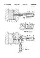
- FIG. 1shows a horizontal die casting apparatus with a shot sleeve arrangement according to the prior art.
- the die 10includes an ejector die 12 mounted to a movable platen 14 and a cover die 16 mounted to a stationary platen 18. Together, the dies 12 and 16 form a cavity 19 into which a shot of molten metal will be introduced.
- a cylindrical shot sleeve 20is disposed passing axially through the stationary platen 18 and the cover die 16 in fluid communication with the cavity 19.
- the upper surface of the outer wall near the end of the shot sleeve 20is penetrated by an open pouring or filling hole 22. Molten metal 24 is ladled through the filling hole 22 into the interior of the shot sleeve 20.
- a plunger 26seals off the outer end of the shot sleeve and reciprocates within the shot sleeve 20 to inject the molten metal into the die.
- the plunger 26is connected axially to a plunger rod 28, crosshead adapter 30, and shot cylinder 32.
- the shot cylinder 32is typically a hydraulic cylinder having a reciprocating shot cylinder rod 34 which causes the plunger 26 to advance toward the die 10 and withdraw therefrom.
- the outer end 36 of the shot cylinder rodis threaded to allow for adjustment of the shot size and stroke length.
- the diameter of the sleeve 20must be enlarged to provide an air space as well as for the necessary volume of molten metal. This enlargement of the shot sleeve diameter reduces the mechanical advantage of the shot cylinder 32, making the apparatus less suitable for squeeze casting.
- FIG. 2shows the effect of the injection stroke of the plunger 26 on the molten metal 24. Since the molten metal does not completely fill the interior of the shot sleeve 20, a rolling, turbulent wave 40 of molten metal is created. Such turbulence in turn causes the formation of air bubbles 42 within the molten metal. The air bubbles ultimately cause unwanted porosity in the castings.
- the present inventionsatisfies the aforementioned need by providing a molten metal filling cylinder axially offset to the shot sleeve which overlaps and partially intersects the shot sleeve such that the bore of the filling cylinder is in fluid communication with the filling hole of the shot sleeve.
- Molten metalis introduced into the filling cylinder.
- the molten metalpasses from the filling cylinder through the filling hole into the shot sleeve until the shot sleeve is completely filled with molten metal.
- the filling cylinderincludes a piston-like, reciprocating internal slide valve which then moves into position to seal off the filling hole. As a result, the shot sleeve is completely filled with molten metal and pressure sealed prior to the advancement of the plunger.
- the present inventioneliminates air entrainment and resultant porosity.
- the diameter of the shot sleeve and the plungerare minimized so that mechanical advantage and shot pressure may be increased for squeeze casting.
- the inventionis suitable for use with both horizontal and vertical die casting apparatus.
- FIG. 1is a sectional, side elevational view of a die casting apparatus according to the prior art
- FIG. 2is a an enlarged, sectional elevational view of the prior art apparatus of FIG. 1 illustrating the effects of the advancement of the plunger in the shot sleeve partially filled with molten metal;
- FIG. 3is a side elevational view, with parts in vertical section of a die casting apparatus according to the principles of the invention
- FIG. 4is a perspective view of the intersecting shot sleeve and filling cylinder
- FIG. 5is a sectional view taken substantially along the line 5--5 of FIG. 3;
- FIG. 5ais a fragmentary, sectional view of the outer end of the filling cylinder similar to FIG. 5 but with the slide valve in the closed position;
- FIG. 6is a side elevational view, with parts in vertical section of a vertical die casting apparatus according to an alternate embodiment of the invention.
- FIG. 3a closed shot die casting apparatus which includes in its general organization a die 10 having ejector and cover dies 12 and 16, movable and stationary platens 14 and 18, cavity 19, hydraulic shot cylinder 32, adjustment threads 36, rod 34, crosshead adapter 30, plunger rod 28, and plunger 26.
- the die, hydraulic shot cylinder, and plungerare substantially the same as described above with respect to the prior art shown in FIG. 1.
- the apparatus of FIG. 3further includes a shot sleeve 50, filling cylinder 52, and hydraulic cylinder 54.
- Shot sleeve 50is similar to the shot sleeve 20 according to the prior art, but may be formed with a smaller diameter. Referring additionally to FIGS. 4 and 5, it may be seen that the shot sleeve 50 and filling cylinder 52 are so that a central extent of the filling cylinder overlaps the filling cylinder with their longitudinal axes perpendicularly offset to one another. The axis of the filling cylinder 52 crosses spaced apart above the axis of the shot sleeve 50. Thus, as best shown in FIG.
- the spacing of the axesis such that the internal bore 56 of the shot sleeve and the internal bore 58 of the filling cylinder partially intersect. This intersection coincides with a filling hole 60 formed through the outer wall of the shot sleeve adjacent the outer end of the shot sleeve by which the shot sleeve and filling cylinder are in fluid communication. As shown in FIG. 4, the shot sleeve 50 and filling cylinder 52 are clamped together at their intersection in fluid-tight relationship by U-bolts 62.
- Hydraulic cylinder 54is mounted by a suitable base 63 and includes reciprocating rod 64.
- the outer end of rod 64is coaxially coupled to a piston-like slide valve 66.
- Slide valve 66thus moves reciprocatingly within the bore of the filling cylinder 52 actuated by hydraulic cylinder 52.
- slide valve 66is shown in its retracted, or filling, position. In this position, the filling hole 60 is open and in fluid communication with the bore 58 of the filling cylinder.
- molten metalis poured into the open outer end 68 of the filling cylinder 52. Pouring may be accomplished by ladling directly into the open end, through a funnel, or other suitable means. As best shown in FIG. 5, the filling cylinder 52 is tilted so that the molten metal runs down to the shot sleeve. The molten metal passes down the bore 58 of the filling cylinder, through the filling hole 60, and into the bore 56 of the shot sleeve 50. The shot sleeve is filled to overflowing such that the molten metal 24 covers the filling hole 60.
- Hydraulic cylinder 54is then actuated to extend the rod 64 and move the slide valve 66 toward the hole 60.
- the slide valve 66overlies the filling hole 60 and makes a fluid tight seal therewith prevent pressurized molten metal from exiting the filling hole when the plunger 26 is actuated.
- the sealing end of the slide valve 66is formed with a recess 70 in the form of a segment of a cylindrical segment complementary in shape to the bore of the shot sleeve 50.
- the recess 70permits the plunger 26 to reciprocate within the shot sleeve past the filling hole 60 without interference from the slide valve 66.
- a receptacle 72may be provided beneath the open outer end 68 to catch any molten metal pushed out of the filling cylinder 52 by the slide valve 66.
- FIGS. 3-5aAn operating cycle of the apparatus of shown in FIGS. 3-5a is described as follows: Initially, die parts 12 and 16 are separated, and hydraulic cylinders 32 and 54 are extended. Die parts 12, 16 are brought together to form a cavity 19 in fluid communication with the inner end of the shot sleeve 50. Hydraulic cylinder 32 is retracted to withdraw the plunger 26 to the position shown in FIG. 3. Next, hydraulic cylinder 54 is retracted to withdraw the slide valve 66 to the position of FIG. 5. Molten metal is poured into the open end 68 of the filling cylinder until interior of the shot sleeve 50 is filled to overflowing with molten metal.
- hydraulic cylinder 54is extended so that slide valve 66 moves into the position of FIG. 5a to seal off the filling hole 60 and contain the molten metal within the shot sleeve 50.
- Cylinder 32is then actuated to forcibly extend the plunger 26 and drive the molten metal from the shot sleeve into the mold cavity. No air is entrained in the metal. High pressures may be developed in the metal for squeeze casting. Finally, the die parts are separated and the casting is removed.
- FIG. 6An alternate embodiment of the invention in a vertical die casting system is show in FIG. 6.
- the vertical systemincludes a die 80, a hydraulic shot cylinder 82, plunger 84, shot sleeve 86, hydraulic cylinder 88, filling cylinder 90, and slide valve 92.
- the hydraulic cylinder 82, plunger 84, and shot sleeve 80are coaxial and vertically oriented with the upper end opening 94 of the shot sleeve in fluid communication with the cavity of the die.
- filling cylinder 90is situated with its axis angularly offset to the shot sleeve axis and spaced apart from the shot sleeve axis where the axes cross.
- Filling cylinder 92overlaps and partially intersects the shot sleeve 86 such that the internal bores of both are in fluid communication through a filling opening or hole 96.
- FIG. 6further illustrates an alternate means for introducing molten metal into the filling cylinder which eliminates the need for ladling and seals the filling system from the atmosphere.
- the axis of the filling cylinder 90is tilted upwardly toward a reservoir 98 of molten metal.
- the lower extent of the reservoir 98is formed with an opening 100 which leads to a downwardly sloping passage 102.
- the lower end of the passage 102is connected to the upper end opening 104 of the filling cylinder 90.
- hydraulic cylinder 88extends the slide valve 92 to seal off the filling hole 96.
- Slide valve 92is formed with a recess (not shown) similarly to the recess 70 shown in FIG. 5a to allow the plunger 84 to pass the filling hole 96 without interference.
- the inventionis easily adaptable to convert a conventional die cast apparatus to squeeze cast apparatus in which relatively high pressures are developed in the injected molten metal.
- Conventional intensification systemsmay be used with the invention.
- Existing shot stroke adjustmentis used to adjust shot size.
- the inventionis suitable for casting steel, aluminum, magnesium, as well as other metallic and nonmetallic materials. The movements of the plunger and the slide valve keep the pouring paths clear.
Landscapes
- Engineering & Computer Science (AREA)
- Mechanical Engineering (AREA)
- Injection Moulding Of Plastics Or The Like (AREA)
Abstract
Description
Claims (27)
Priority Applications (7)
| Application Number | Priority Date | Filing Date | Title |
|---|---|---|---|
| US07/805,033US5205338A (en) | 1991-12-11 | 1991-12-11 | Closed shot die casting |
| CA002068058ACA2068058C (en) | 1991-12-11 | 1992-05-06 | Closed shot die casting system |
| MX9204662AMX9204662A (en) | 1991-12-11 | 1992-08-12 | METHOD AND APPARATUS FOR DIE MOLDING OF CAST MATERIAL. |
| DE69222510TDE69222510T2 (en) | 1991-12-11 | 1992-10-20 | Closed die casting system |
| ES92309573TES2109319T3 (en) | 1991-12-11 | 1992-10-20 | CLOSED FILLING CYLINDER FOR LOW PRESSURE CASTING. |
| EP92309573AEP0546664B1 (en) | 1991-12-11 | 1992-10-20 | Closed shot die casting |
| JP4295884AJPH084902B2 (en) | 1991-12-11 | 1992-11-05 | Closed injection die casting method |
Applications Claiming Priority (1)
| Application Number | Priority Date | Filing Date | Title |
|---|---|---|---|
| US07/805,033US5205338A (en) | 1991-12-11 | 1991-12-11 | Closed shot die casting |
Publications (1)
| Publication Number | Publication Date |
|---|---|
| US5205338Atrue US5205338A (en) | 1993-04-27 |
Family
ID=25190531
Family Applications (1)
| Application Number | Title | Priority Date | Filing Date |
|---|---|---|---|
| US07/805,033Expired - Fee RelatedUS5205338A (en) | 1991-12-11 | 1991-12-11 | Closed shot die casting |
Country Status (7)
| Country | Link |
|---|---|
| US (1) | US5205338A (en) |
| EP (1) | EP0546664B1 (en) |
| JP (1) | JPH084902B2 (en) |
| CA (1) | CA2068058C (en) |
| DE (1) | DE69222510T2 (en) |
| ES (1) | ES2109319T3 (en) |
| MX (1) | MX9204662A (en) |
Cited By (22)
| Publication number | Priority date | Publication date | Assignee | Title |
|---|---|---|---|---|
| EP0694357A1 (en)* | 1994-07-25 | 1996-01-31 | Nelson Metal Products Corporation | Apparatus for die casting |
| US5630463A (en)* | 1994-12-08 | 1997-05-20 | Nelson Metal Products Corporation | Variable volume die casting shot sleeve |
| US5730202A (en)* | 1996-03-18 | 1998-03-24 | Nelson Metal Products Corporation | Constant volume shot sleeve |
| US5983976A (en)* | 1998-03-31 | 1999-11-16 | Takata Corporation | Method and apparatus for manufacturing metallic parts by fine die casting |
| US6065526A (en)* | 1995-09-01 | 2000-05-23 | Takata Corporation | Method and apparatus for manufacturing light metal alloy |
| US6135196A (en)* | 1998-03-31 | 2000-10-24 | Takata Corporation | Method and apparatus for manufacturing metallic parts by injection molding from the semi-solid state |
| US6230786B1 (en)* | 1998-05-26 | 2001-05-15 | Shin-Ei Die Casting Ind. Co., Ltd. | Automatic molten metal supply and injection device |
| US6474399B2 (en) | 1998-03-31 | 2002-11-05 | Takata Corporation | Injection molding method and apparatus with reduced piston leakage |
| US6540006B2 (en) | 1998-03-31 | 2003-04-01 | Takata Corporation | Method and apparatus for manufacturing metallic parts by fine die casting |
| US6666258B1 (en) | 2000-06-30 | 2003-12-23 | Takata Corporation | Method and apparatus for supplying melted material for injection molding |
| US20040084170A1 (en)* | 2002-10-30 | 2004-05-06 | Ervin Leonard L. | Die casting |
| US6742570B2 (en) | 2002-05-01 | 2004-06-01 | Takata Corporation | Injection molding method and apparatus with base mounted feeder |
| US20040231819A1 (en)* | 2003-05-19 | 2004-11-25 | Takata Corporation | Vertical injection machine using gravity feed |
| US20040231821A1 (en)* | 2003-05-19 | 2004-11-25 | Takata Corporation | Vertical injection machine using three chambers |
| US20040231820A1 (en)* | 2003-05-19 | 2004-11-25 | Takata Corporation | Method and apparatus for manufacturing metallic parts by die casting |
| KR100554093B1 (en)* | 2004-02-04 | 2006-02-22 | 주식회사 나노캐스트코리아 | Reactor High Molding Device |
| US20070163743A1 (en)* | 2003-06-03 | 2007-07-19 | Go Dong K | Die casting machine and casting method by therof machine |
| WO2010017959A3 (en)* | 2008-08-11 | 2010-04-22 | Aap Biomaterials Gmbh | Implant made of a magnesium alloy and method for the production thereof |
| US20170136527A1 (en)* | 2015-11-16 | 2017-05-18 | GM Global Technology Operations LLC | High pressure die cast machine |
| US9676024B2 (en) | 2012-06-04 | 2017-06-13 | Gebr. Krallmann Gmbh | Conveying device for molten metal in an injection die casting unit |
| CN106984794A (en)* | 2017-03-31 | 2017-07-28 | 福州大学 | The co-extrusion pressure Preparation equipment and application method of xenogenesis ply-metal |
| CN112719245A (en)* | 2021-03-08 | 2021-04-30 | 金雅豪精密金属科技(深圳)股份有限公司 | Perpendicular die-casting ranking structure of cell-phone medium plate and perpendicular die casting machine |
Citations (17)
| Publication number | Priority date | Publication date | Assignee | Title |
|---|---|---|---|---|
| BE565457A (en)* | ||||
| US359757A (en)* | 1887-03-22 | Method of making plumbersj traps | ||
| US2137764A (en)* | 1936-03-19 | 1938-11-22 | Wagner Karl Friedrich | Apparatus for casting metal under pressure |
| DE935147C (en)* | 1954-01-24 | 1955-11-10 | Mahle Werk G M B H | Press casting machine |
| US2972172A (en)* | 1958-01-22 | 1961-02-21 | Alfred P Federman | Method for feeding liquid casting material into an article mold |
| US3019495A (en)* | 1958-05-28 | 1962-02-06 | Litemetal Dicast Inc | Die casting |
| US3292218A (en)* | 1965-04-29 | 1966-12-20 | J A Kozma Company | Automatic metal injection system |
| US3646990A (en)* | 1969-10-10 | 1972-03-07 | Raymond E Cross | Die casting machine |
| US3791440A (en)* | 1970-12-07 | 1974-02-12 | R Cross | Die casting method |
| US3810505A (en)* | 1970-12-07 | 1974-05-14 | R Cross | Die casting method |
| JPS58196159A (en)* | 1982-05-12 | 1983-11-15 | Honda Motor Co Ltd | Die for forging of molten metal |
| US4436140A (en)* | 1979-01-26 | 1984-03-13 | Honda Giken Kogyo Kabushiki Kaisha | Method of charging molten metal into a vertical die casting machine |
| US4505318A (en)* | 1982-06-04 | 1985-03-19 | Toyoto Jidosha Kogyo Kabushiki Kaisha | Vertical type pressure casting method |
| US4519436A (en)* | 1980-01-21 | 1985-05-28 | Honda Giken Kogyo Kabushiki Kaisha | Method for injecting molten metal in vertical diecasting machine |
| JPS60102259A (en)* | 1983-11-09 | 1985-06-06 | Honda Motor Co Ltd | High pressure solidification casting equipment |
| US4614463A (en)* | 1985-09-11 | 1986-09-30 | Hughes Chesley P | Cutter having removable cutting blades |
| US4730658A (en)* | 1985-11-26 | 1988-03-15 | Akio Nakano | Injection method in a hot chamber type die casting machine and injection apparatus for carrying the method |
Family Cites Families (4)
| Publication number | Priority date | Publication date | Assignee | Title |
|---|---|---|---|---|
| GB475543A (en)* | 1936-02-21 | 1937-11-22 | Karl Friedrich Wagner | Improvements in compression casting-machines for easily oxidizable metals |
| JPS5227106A (en)* | 1975-08-27 | 1977-03-01 | Hitachi Ltd | Railway train operation control system |
| JPS62286659A (en)* | 1986-06-05 | 1987-12-12 | Toshiba Mach Co Ltd | Molten metal supplying apparatus |
| CA2024327C (en)* | 1990-08-30 | 1995-09-26 | Stephen Yaffe | Magnesium die casting machine |
- 1991
- 1991-12-11USUS07/805,033patent/US5205338A/ennot_activeExpired - Fee Related
- 1992
- 1992-05-06CACA002068058Apatent/CA2068058C/ennot_activeExpired - Fee Related
- 1992-08-12MXMX9204662Apatent/MX9204662A/ennot_activeIP Right Cessation
- 1992-10-20DEDE69222510Tpatent/DE69222510T2/ennot_activeExpired - Fee Related
- 1992-10-20EPEP92309573Apatent/EP0546664B1/ennot_activeExpired - Lifetime
- 1992-10-20ESES92309573Tpatent/ES2109319T3/ennot_activeExpired - Lifetime
- 1992-11-05JPJP4295884Apatent/JPH084902B2/ennot_activeExpired - Lifetime
Patent Citations (17)
| Publication number | Priority date | Publication date | Assignee | Title |
|---|---|---|---|---|
| BE565457A (en)* | ||||
| US359757A (en)* | 1887-03-22 | Method of making plumbersj traps | ||
| US2137764A (en)* | 1936-03-19 | 1938-11-22 | Wagner Karl Friedrich | Apparatus for casting metal under pressure |
| DE935147C (en)* | 1954-01-24 | 1955-11-10 | Mahle Werk G M B H | Press casting machine |
| US2972172A (en)* | 1958-01-22 | 1961-02-21 | Alfred P Federman | Method for feeding liquid casting material into an article mold |
| US3019495A (en)* | 1958-05-28 | 1962-02-06 | Litemetal Dicast Inc | Die casting |
| US3292218A (en)* | 1965-04-29 | 1966-12-20 | J A Kozma Company | Automatic metal injection system |
| US3646990A (en)* | 1969-10-10 | 1972-03-07 | Raymond E Cross | Die casting machine |
| US3791440A (en)* | 1970-12-07 | 1974-02-12 | R Cross | Die casting method |
| US3810505A (en)* | 1970-12-07 | 1974-05-14 | R Cross | Die casting method |
| US4436140A (en)* | 1979-01-26 | 1984-03-13 | Honda Giken Kogyo Kabushiki Kaisha | Method of charging molten metal into a vertical die casting machine |
| US4519436A (en)* | 1980-01-21 | 1985-05-28 | Honda Giken Kogyo Kabushiki Kaisha | Method for injecting molten metal in vertical diecasting machine |
| JPS58196159A (en)* | 1982-05-12 | 1983-11-15 | Honda Motor Co Ltd | Die for forging of molten metal |
| US4505318A (en)* | 1982-06-04 | 1985-03-19 | Toyoto Jidosha Kogyo Kabushiki Kaisha | Vertical type pressure casting method |
| JPS60102259A (en)* | 1983-11-09 | 1985-06-06 | Honda Motor Co Ltd | High pressure solidification casting equipment |
| US4614463A (en)* | 1985-09-11 | 1986-09-30 | Hughes Chesley P | Cutter having removable cutting blades |
| US4730658A (en)* | 1985-11-26 | 1988-03-15 | Akio Nakano | Injection method in a hot chamber type die casting machine and injection apparatus for carrying the method |
Cited By (43)
| Publication number | Priority date | Publication date | Assignee | Title |
|---|---|---|---|---|
| US5529110A (en)* | 1994-07-25 | 1996-06-25 | Nelson Metal Products Corporation | Rotary actuated closed shot die casting |
| EP0694357A1 (en)* | 1994-07-25 | 1996-01-31 | Nelson Metal Products Corporation | Apparatus for die casting |
| US5630463A (en)* | 1994-12-08 | 1997-05-20 | Nelson Metal Products Corporation | Variable volume die casting shot sleeve |
| US5730199A (en)* | 1994-12-08 | 1998-03-24 | Nelson Metal Products Corporation | Die casting articles having an insert |
| US6065526A (en)* | 1995-09-01 | 2000-05-23 | Takata Corporation | Method and apparatus for manufacturing light metal alloy |
| US6739379B2 (en) | 1995-09-01 | 2004-05-25 | Takata Corporation | Method and apparatus for manufacturing light metal alloy |
| US6241001B1 (en) | 1995-09-01 | 2001-06-05 | Takata Corporation | Method and apparatus for manufacturing light metal alloy |
| EP0796686A3 (en)* | 1996-03-18 | 1998-12-02 | Nelson Metal Products Corporation | Shot sleeve for a die casting apparatus |
| US5730202A (en)* | 1996-03-18 | 1998-03-24 | Nelson Metal Products Corporation | Constant volume shot sleeve |
| US6135196A (en)* | 1998-03-31 | 2000-10-24 | Takata Corporation | Method and apparatus for manufacturing metallic parts by injection molding from the semi-solid state |
| US5983976A (en)* | 1998-03-31 | 1999-11-16 | Takata Corporation | Method and apparatus for manufacturing metallic parts by fine die casting |
| US6276434B1 (en) | 1998-03-31 | 2001-08-21 | Takata Corporation | Method and apparatus for manufacturing metallic parts by ink injection molding from the semi-solid state |
| US6283197B1 (en) | 1998-03-31 | 2001-09-04 | Takata Corporation | Method and apparatus for manufacturing metallic parts by fine die casting |
| US6474399B2 (en) | 1998-03-31 | 2002-11-05 | Takata Corporation | Injection molding method and apparatus with reduced piston leakage |
| US6540006B2 (en) | 1998-03-31 | 2003-04-01 | Takata Corporation | Method and apparatus for manufacturing metallic parts by fine die casting |
| US6655445B2 (en) | 1998-03-31 | 2003-12-02 | Takata Corporation | Injection molding method and apparatus with reduced piston leakage |
| US20040074626A1 (en)* | 1998-03-31 | 2004-04-22 | Takata Corporation | Injection molding method and apparatus with reduced piston leakage |
| US6942006B2 (en) | 1998-03-31 | 2005-09-13 | Takata Corporation | Injection molding method and apparatus with reduced piston leakage |
| US6230786B1 (en)* | 1998-05-26 | 2001-05-15 | Shin-Ei Die Casting Ind. Co., Ltd. | Automatic molten metal supply and injection device |
| US6666258B1 (en) | 2000-06-30 | 2003-12-23 | Takata Corporation | Method and apparatus for supplying melted material for injection molding |
| US6742570B2 (en) | 2002-05-01 | 2004-06-01 | Takata Corporation | Injection molding method and apparatus with base mounted feeder |
| US6789603B2 (en) | 2002-05-01 | 2004-09-14 | Takata Corporation | Injection molding method and apparatus with base mounted feeder |
| US20040084170A1 (en)* | 2002-10-30 | 2004-05-06 | Ervin Leonard L. | Die casting |
| US6805189B2 (en) | 2002-10-30 | 2004-10-19 | Howmet Research Corporation | Die casting |
| US6880614B2 (en) | 2003-05-19 | 2005-04-19 | Takata Corporation | Vertical injection machine using three chambers |
| US20040231820A1 (en)* | 2003-05-19 | 2004-11-25 | Takata Corporation | Method and apparatus for manufacturing metallic parts by die casting |
| US20050022958A1 (en)* | 2003-05-19 | 2005-02-03 | Takata Corporation | Method and apparatus for manufacturing metallic parts by die casting |
| US20040231821A1 (en)* | 2003-05-19 | 2004-11-25 | Takata Corporation | Vertical injection machine using three chambers |
| US6945310B2 (en) | 2003-05-19 | 2005-09-20 | Takata Corporation | Method and apparatus for manufacturing metallic parts by die casting |
| US6951238B2 (en) | 2003-05-19 | 2005-10-04 | Takata Corporation | Vertical injection machine using gravity feed |
| US20040231819A1 (en)* | 2003-05-19 | 2004-11-25 | Takata Corporation | Vertical injection machine using gravity feed |
| US7150308B2 (en) | 2003-05-19 | 2006-12-19 | Takata Corporation | Method and apparatus for manufacturing metallic parts by die casting |
| US7296611B2 (en) | 2003-05-19 | 2007-11-20 | Advanced Technologies, Inc. | Method and apparatus for manufacturing metallic parts by die casting |
| US7377303B2 (en)* | 2003-06-03 | 2008-05-27 | Dong Keun Go | Die casting machine and casting method by thereof machine |
| US20070163743A1 (en)* | 2003-06-03 | 2007-07-19 | Go Dong K | Die casting machine and casting method by therof machine |
| KR100554093B1 (en)* | 2004-02-04 | 2006-02-22 | 주식회사 나노캐스트코리아 | Reactor High Molding Device |
| WO2010017959A3 (en)* | 2008-08-11 | 2010-04-22 | Aap Biomaterials Gmbh | Implant made of a magnesium alloy and method for the production thereof |
| CN102170921A (en)* | 2008-08-11 | 2011-08-31 | App生物材料有限公司 | Implant made of magnesium and magnesium alloy for an implant, and method for the production thereof |
| DE102008037200B4 (en)* | 2008-08-11 | 2015-07-09 | Aap Implantate Ag | Use of a die-casting method for producing a magnesium implant and magnesium alloy |
| US9676024B2 (en) | 2012-06-04 | 2017-06-13 | Gebr. Krallmann Gmbh | Conveying device for molten metal in an injection die casting unit |
| US20170136527A1 (en)* | 2015-11-16 | 2017-05-18 | GM Global Technology Operations LLC | High pressure die cast machine |
| CN106984794A (en)* | 2017-03-31 | 2017-07-28 | 福州大学 | The co-extrusion pressure Preparation equipment and application method of xenogenesis ply-metal |
| CN112719245A (en)* | 2021-03-08 | 2021-04-30 | 金雅豪精密金属科技(深圳)股份有限公司 | Perpendicular die-casting ranking structure of cell-phone medium plate and perpendicular die casting machine |
Also Published As
| Publication number | Publication date |
|---|---|
| DE69222510T2 (en) | 1998-04-16 |
| CA2068058A1 (en) | 1993-06-12 |
| DE69222510D1 (en) | 1997-11-06 |
| JPH084902B2 (en) | 1996-01-24 |
| CA2068058C (en) | 1996-12-17 |
| EP0546664A1 (en) | 1993-06-16 |
| ES2109319T3 (en) | 1998-01-16 |
| JPH05212520A (en) | 1993-08-24 |
| MX9204662A (en) | 1993-06-01 |
| EP0546664B1 (en) | 1997-10-01 |
Similar Documents
| Publication | Publication Date | Title |
|---|---|---|
| US5205338A (en) | Closed shot die casting | |
| US5127814A (en) | Apparatus for producing a fluid-assisted injection molded product | |
| US3270383A (en) | Method of die casting | |
| KR910009623B1 (en) | Pressing device for casting equipment | |
| US5728410A (en) | System for injection molding of plastic article utilizing a variable volume spill cavity | |
| US5181551A (en) | Double acting cylinder for filling dies with molten metal | |
| US20070074842A1 (en) | Shot sleeve insert and method of retarding heat erosion within a shot sleeve bore | |
| US5601136A (en) | Inclined die cast shot sleeve system | |
| CA2567290A1 (en) | Vertical casting apparatus and vertical casting method | |
| KR19990008273A (en) | Method and system for injection molding and production of articles using variable volume spill cavities | |
| JP2802266B2 (en) | Shot sleeve device, shot sleeve, die casting device, and die casting method | |
| US6880614B2 (en) | Vertical injection machine using three chambers | |
| CA1252267A (en) | Casting apparatus | |
| AU638902B1 (en) | Closed shot die casting system | |
| US5207264A (en) | Vertical die casting machine | |
| US4354545A (en) | Modified pressure casting process | |
| US5971057A (en) | Injection molding machine and injection molding method | |
| US6250368B1 (en) | Casting mold for producing a fiber-reinforced composite article by die-casting process | |
| US5529110A (en) | Rotary actuated closed shot die casting | |
| US5595236A (en) | Vertical squeeze casting apparatus | |
| US6062294A (en) | Injection molding machine and injection molding method | |
| US3700025A (en) | Method of casting quiet melts | |
| US5299623A (en) | Magnesium die casting machine | |
| US5657833A (en) | Self-contained unitized lubricant delivery apparatus | |
| KR101662519B1 (en) | Die casting apparatus including a sleeve easy to remove a gas |
Legal Events
| Date | Code | Title | Description |
|---|---|---|---|
| AS | Assignment | Owner name:NELSON METAL PRODUCTS CORPORATION, MICHIGAN Free format text:ASSIGNMENT OF ASSIGNORS INTEREST.;ASSIGNOR:SHIMMELL, DENNIS S.;REEL/FRAME:005950/0779 Effective date:19911119 | |
| FPAY | Fee payment | Year of fee payment:4 | |
| FEPP | Fee payment procedure | Free format text:PAT HLDR NO LONGER CLAIMS SMALL ENT STAT AS SMALL BUSINESS (ORIGINAL EVENT CODE: LSM2); ENTITY STATUS OF PATENT OWNER: LARGE ENTITY | |
| AS | Assignment | Owner name:CHASE MANHATTAN BANK, AS COLLATERAL AGENT, THE, NE Free format text:AMENDED AND RESTATED GUARANTEE AND COLLATERAL AGREEMENT;ASSIGNOR:NELSON METAL PRODUCTS CORPORATION (MICHIGAN CORPORATION);REEL/FRAME:010506/0570 Effective date:19991015 | |
| FPAY | Fee payment | Year of fee payment:8 | |
| AS | Assignment | Owner name:JPMORGAN CHASE BANK, NEW YORK Free format text:SECURITY INTEREST;ASSIGNOR:NELSON METAL PRODUCTS CORPORATION;REEL/FRAME:013653/0073 Effective date:20021227 | |
| AS | Assignment | Owner name:NELSON METAL PRODUCTS CORPORATION, MICHIGAN Free format text:RELEASE OF SECURITY INTEREST IN PATENTS;ASSIGNOR:JP MORGAN CHASE, F/K/A THE CHASE MANHATTAN BANK, AS COLLATERAL AGENT;REEL/FRAME:015056/0125 Effective date:20040823 Owner name:NELSON METAL PRODUCTS CORPORATION, MICHIGAN Free format text:RELEASE OF SECURITY INTEREST IN PATENTS;ASSIGNOR:JP MORGAN CHASE BANK, F/K/A/ THE CHASE MANHATTAN BANK, AS COLLATERAL AGENT;REEL/FRAME:015056/0194 Effective date:20040823 Owner name:GENERAL ELECTRIC CAPITAL CORPORATION, AS COLLATERA Free format text:FIRST LIEN PATENT SECURITY AGREEMENT;ASSIGNORS:J.L. FRENCH AUTOMOTIVE CASTINGS, INC.;NELSON METAL PRODUCTS CORPORATION;FRENCH HOLDINGS, INC.;AND OTHERS;REEL/FRAME:015056/0264 Effective date:20040823 Owner name:GOLDMAN SACHS CREDIT PARTNERS L.P., AS COLLATERAL Free format text:SECOND LIEN PATENT SECURITY AGREEMENT;ASSIGNORS:J.L. FRENCH AUTOMOTIVE CASTINGS, INC.;NELSON METAL PRODUCTS CORPORATION;FRENCH HOLDINGS, INC.;AND OTHERS;REEL/FRAME:015056/0299 Effective date:20040823 | |
| REMI | Maintenance fee reminder mailed | ||
| LAPS | Lapse for failure to pay maintenance fees | ||
| STCH | Information on status: patent discontinuation | Free format text:PATENT EXPIRED DUE TO NONPAYMENT OF MAINTENANCE FEES UNDER 37 CFR 1.362 | |
| FP | Lapsed due to failure to pay maintenance fee | Effective date:20050427 |