US5205017A - Notebook computer top cover mounting hardware - Google Patents
Notebook computer top cover mounting hardwareDownload PDFInfo
- Publication number
- US5205017A US5205017AUS07/853,058US85305892AUS5205017AUS 5205017 AUS5205017 AUS 5205017AUS 85305892 AUS85305892 AUS 85305892AUS 5205017 AUS5205017 AUS 5205017A
- Authority
- US
- United States
- Prior art keywords
- top cover
- annular groove
- movable support
- opposite
- mainframe
- Prior art date
- Legal status (The legal status is an assumption and is not a legal conclusion. Google has not performed a legal analysis and makes no representation as to the accuracy of the status listed.)
- Expired - Fee Related
Links
Images


Classifications
- G—PHYSICS
- G06—COMPUTING OR CALCULATING; COUNTING
- G06F—ELECTRIC DIGITAL DATA PROCESSING
- G06F1/00—Details not covered by groups G06F3/00 - G06F13/00 and G06F21/00
- G06F1/16—Constructional details or arrangements
- G06F1/1613—Constructional details or arrangements for portable computers
- G06F1/1633—Constructional details or arrangements of portable computers not specific to the type of enclosures covered by groups G06F1/1615 - G06F1/1626
- G06F1/1675—Miscellaneous details related to the relative movement between the different enclosures or enclosure parts
- G06F1/1683—Miscellaneous details related to the relative movement between the different enclosures or enclosure parts for the transmission of signal or power between the different housings, e.g. details of wired or wireless communication, passage of cabling
- G—PHYSICS
- G06—COMPUTING OR CALCULATING; COUNTING
- G06F—ELECTRIC DIGITAL DATA PROCESSING
- G06F1/00—Details not covered by groups G06F3/00 - G06F13/00 and G06F21/00
- G06F1/16—Constructional details or arrangements
- G06F1/1613—Constructional details or arrangements for portable computers
- G06F1/1615—Constructional details or arrangements for portable computers with several enclosures having relative motions, each enclosure supporting at least one I/O or computing function
- G06F1/1616—Constructional details or arrangements for portable computers with several enclosures having relative motions, each enclosure supporting at least one I/O or computing function with folding flat displays, e.g. laptop computers or notebooks having a clamshell configuration, with body parts pivoting to an open position around an axis parallel to the plane they define in closed position
- G06F1/162—Constructional details or arrangements for portable computers with several enclosures having relative motions, each enclosure supporting at least one I/O or computing function with folding flat displays, e.g. laptop computers or notebooks having a clamshell configuration, with body parts pivoting to an open position around an axis parallel to the plane they define in closed position changing, e.g. reversing, the face orientation of the screen with a two degrees of freedom mechanism, e.g. for folding into tablet PC like position or orienting towards the direction opposite to the user to show to a second user
- G—PHYSICS
- G06—COMPUTING OR CALCULATING; COUNTING
- G06F—ELECTRIC DIGITAL DATA PROCESSING
- G06F1/00—Details not covered by groups G06F3/00 - G06F13/00 and G06F21/00
- G06F1/16—Constructional details or arrangements
- G06F1/1613—Constructional details or arrangements for portable computers
- G06F1/1633—Constructional details or arrangements of portable computers not specific to the type of enclosures covered by groups G06F1/1615 - G06F1/1626
- G06F1/1637—Details related to the display arrangement, including those related to the mounting of the display in the housing
- G06F1/1643—Details related to the display arrangement, including those related to the mounting of the display in the housing the display being associated to a digitizer, e.g. laptops that can be used as penpads
- G—PHYSICS
- G06—COMPUTING OR CALCULATING; COUNTING
- G06F—ELECTRIC DIGITAL DATA PROCESSING
- G06F1/00—Details not covered by groups G06F3/00 - G06F13/00 and G06F21/00
- G06F1/16—Constructional details or arrangements
- G06F1/1613—Constructional details or arrangements for portable computers
- G06F1/1633—Constructional details or arrangements of portable computers not specific to the type of enclosures covered by groups G06F1/1615 - G06F1/1626
- G06F1/1675—Miscellaneous details related to the relative movement between the different enclosures or enclosure parts
- G06F1/1681—Details related solely to hinges
- E—FIXED CONSTRUCTIONS
- E05—LOCKS; KEYS; WINDOW OR DOOR FITTINGS; SAFES
- E05D—HINGES OR SUSPENSION DEVICES FOR DOORS, WINDOWS OR WINGS
- E05D3/00—Hinges with pins
- E05D3/06—Hinges with pins with two or more pins
- E05D3/10—Hinges with pins with two or more pins with non-parallel pins
- E—FIXED CONSTRUCTIONS
- E05—LOCKS; KEYS; WINDOW OR DOOR FITTINGS; SAFES
- E05Y—INDEXING SCHEME ASSOCIATED WITH SUBCLASSES E05D AND E05F, RELATING TO CONSTRUCTION ELEMENTS, ELECTRIC CONTROL, POWER SUPPLY, POWER SIGNAL OR TRANSMISSION, USER INTERFACES, MOUNTING OR COUPLING, DETAILS, ACCESSORIES, AUXILIARY OPERATIONS NOT OTHERWISE PROVIDED FOR, APPLICATION THEREOF
- E05Y2999/00—Subject-matter not otherwise provided for in this subclass
- Y—GENERAL TAGGING OF NEW TECHNOLOGICAL DEVELOPMENTS; GENERAL TAGGING OF CROSS-SECTIONAL TECHNOLOGIES SPANNING OVER SEVERAL SECTIONS OF THE IPC; TECHNICAL SUBJECTS COVERED BY FORMER USPC CROSS-REFERENCE ART COLLECTIONS [XRACs] AND DIGESTS
- Y10—TECHNICAL SUBJECTS COVERED BY FORMER USPC
- Y10S—TECHNICAL SUBJECTS COVERED BY FORMER USPC CROSS-REFERENCE ART COLLECTIONS [XRACs] AND DIGESTS
- Y10S16/00—Miscellaneous hardware, e.g. bushing, carpet fastener, caster, door closer, panel hanger, attachable or adjunct handle, hinge, window sash balance
- Y10S16/04—Mirror mount
- Y—GENERAL TAGGING OF NEW TECHNOLOGICAL DEVELOPMENTS; GENERAL TAGGING OF CROSS-SECTIONAL TECHNOLOGIES SPANNING OVER SEVERAL SECTIONS OF THE IPC; TECHNICAL SUBJECTS COVERED BY FORMER USPC CROSS-REFERENCE ART COLLECTIONS [XRACs] AND DIGESTS
- Y10—TECHNICAL SUBJECTS COVERED BY FORMER USPC
- Y10S—TECHNICAL SUBJECTS COVERED BY FORMER USPC CROSS-REFERENCE ART COLLECTIONS [XRACs] AND DIGESTS
- Y10S16/00—Miscellaneous hardware, e.g. bushing, carpet fastener, caster, door closer, panel hanger, attachable or adjunct handle, hinge, window sash balance
- Y10S16/41—Coupling, e.g. handle, rod, shaft
Definitions
- the present inventionrelates to notebook computers. More particularly, the present invention relates to a notebook computer top cover mounting hardware which permits the top cover of a notebook computer can be rotated through 180° angle for showing the display thereof to people at any angle.
- notebook computeris the one.
- the displayis generally made on the top cover thereof at the inside so that the total size of the computer can be greatly reduced.
- this arrangementobstructs people from seeing the display from an angle opposed to the operator of a notebook computer. Further, this arrangement is not convenient for data input with a pen device.
- the present inventionhas been accomplished to eliminate the aforesaid problems. It is therefore an object of the present invention to provide a notebook computer top cover mounting hardware which permits the top cover of a notebook computer to be rotated through 180° angle for changing the display thereof to an opposite side. It is another object of the present invention to provide a notebook computer top cover mounting hardware which permits the operation of data input to be performed through a pen device conveniently. It is still another object of the present invention to provide a notebook computer top cover mounting hardware which is inexpensive to make and durable in use.
- a notebook computer top cover mounting hardwarecomprises a mainframe which has a movable support pivoted to a top edge thereof at one side, and a top cover connected to the movable support by a movable rod and a holding plate to hold a display.
- the holding platecomprises a tubular body extending from a flat base, wherein the tubular body has a first annular groove and a second annular groove formed around an inner wall surface thereof at two opposite ends and connected by an elongated groove; the flat base is secured to the movable support at one side.
- the movable rodhas one end fixedly fastened in a hole on the top cover, and an opposite end attached with a side pin.
- the movable rodis held in the holding plate with the side pin thereof engaged in either annular groove. Moving the side pin of the movable rod from the first annular groove to the second annular groove causes the top cover to be rotated through 180° angle for turning the display from a concealed position to the outside for performing a data input operation through a pen device conveniently.
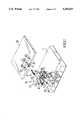
- FIG. 1is an exploded view of the preferred embodiment of the notebook computer of the present invention
- FIG. 2is a sectional assembly view thereof
- FIG. 3is another sectional view thereof showing that the top cover has been lifted from the movable support for changing its angular position;
- FIG. 4is still another sectional view thereof showing that the top cover has been rotated through 180° angle to turn the display thereof to the outside;
- FIG. 5is an elevation view thereof.
- the mainframe as indicated at 1has two adjacent recesses 2, 3 on the top edge thereof at one side separated by a raised block 24.
- the recesses 2, 3each has a peg 4 and 5 transversely projecting inwards at an opposite end.
- the pegs 4, 5are respectively inserted into holes 7, 8 on two opposite sides of a movable support 6 to secure the movable support 6 to the mainframe 1 permitting it to be rotated thereon.
- An elongated, round, movable rod 9which has a side pin 10 at one end is inserted through a hole 12 on a movable rod holding plate 11.
- the holding plate 11comprises a rectangular base 33 held in a rectangular slot 34 on the movable support 6.
- the movable support 6is consisted of an upper plate 13 and a bottom plate 14.
- the upper and bottom plates 13, 14are connected together by screws 15 to firmly secure the holding plate 11 thereto.
- Two opposite sliding ways 16, 17are made on the movable support 6 at two opposite sides for supporting two opposed projecting blocks 19, 20 on a top cover 18.
- the top cover 18has a rectangular opening 21 on a side thereof attached with a frame 23.
- the frame 23may be made from an aluminum alloy.
- the two opposed projecting blocks 19, 20are formed on the frame 23 at two opposite locations inside the rectangular opening 21.
- a hole 22is made on the frame 23 inside the rectangular opening 21 between the two opposed projecting blocks 19, 20 for fastening the movable rod 9.
- the top cover 18After having been connected to a movable support 6 by the movable rod 9, the top cover 18 can be pivoted to the mainframe 1.
- the raised block 24has wire holes 25, 26 for inserting electric wires 32.
- two annular groovesnamely, an upper annular groove 43 and a lower annular groove 44 are made around the inner wall surface of the holding plate 11 inside the hole 12 thereof at two opposite ends.
- the movable rod 9is fastened in the hole 22 on the top cover 18 and held in the hole 12 with its side pin 10 engaged in the lower annular groove 44. Because the holding plate 11 is secured to the movable support 6 and the movable support 6 is pivoted to the mainframe 1, the top cover 18 is pivotably secured to the mainframe 1 by the movable rod 9 via the holding plate 11 and the movable support 6, with the two opposed projecting blocks 19, 20 thereof respectively stopped at the two sliding ways 16, 17.
Landscapes
- Engineering & Computer Science (AREA)
- Computer Hardware Design (AREA)
- Theoretical Computer Science (AREA)
- Physics & Mathematics (AREA)
- Human Computer Interaction (AREA)
- General Engineering & Computer Science (AREA)
- General Physics & Mathematics (AREA)
- Computer Networks & Wireless Communication (AREA)
- Mathematical Physics (AREA)
- Calculators And Similar Devices (AREA)
Abstract
Description
The present invention relates to notebook computers. More particularly, the present invention relates to a notebook computer top cover mounting hardware which permits the top cover of a notebook computer can be rotated through 180° angle for showing the display thereof to people at any angle.
A variety of mobile computers have been known and well accepted by computer users for the advantages of mobility. For example, notebook computer is the one. In a notebook computer, the display is generally made on the top cover thereof at the inside so that the total size of the computer can be greatly reduced. However, this arrangement obstructs people from seeing the display from an angle opposed to the operator of a notebook computer. Further, this arrangement is not convenient for data input with a pen device.
The present invention has been accomplished to eliminate the aforesaid problems. It is therefore an object of the present invention to provide a notebook computer top cover mounting hardware which permits the top cover of a notebook computer to be rotated through 180° angle for changing the display thereof to an opposite side. It is another object of the present invention to provide a notebook computer top cover mounting hardware which permits the operation of data input to be performed through a pen device conveniently. It is still another object of the present invention to provide a notebook computer top cover mounting hardware which is inexpensive to make and durable in use.
According to the present invention, a notebook computer top cover mounting hardware comprises a mainframe which has a movable support pivoted to a top edge thereof at one side, and a top cover connected to the movable support by a movable rod and a holding plate to hold a display. The holding plate comprises a tubular body extending from a flat base, wherein the tubular body has a first annular groove and a second annular groove formed around an inner wall surface thereof at two opposite ends and connected by an elongated groove; the flat base is secured to the movable support at one side. The movable rod has one end fixedly fastened in a hole on the top cover, and an opposite end attached with a side pin. The movable rod is held in the holding plate with the side pin thereof engaged in either annular groove. Moving the side pin of the movable rod from the first annular groove to the second annular groove causes the top cover to be rotated through 180° angle for turning the display from a concealed position to the outside for performing a data input operation through a pen device conveniently.
FIG. 1 is an exploded view of the preferred embodiment of the notebook computer of the present invention;
FIG. 2 is a sectional assembly view thereof;
FIG. 3 is another sectional view thereof showing that the top cover has been lifted from the movable support for changing its angular position;
FIG. 4 is still another sectional view thereof showing that the top cover has been rotated through 180° angle to turn the display thereof to the outside; and
FIG. 5 is an elevation view thereof.
Referring to FIG. 1, the mainframe as indicated at 1 has two adjacent recesses 2, 3 on the top edge thereof at one side separated by a raisedblock 24. The recesses 2, 3 each has apeg 4 and 5 transversely projecting inwards at an opposite end. Thepegs 4, 5 are respectively inserted intoholes 7, 8 on two opposite sides of a movable support 6 to secure the movable support 6 to the mainframe 1 permitting it to be rotated thereon. An elongated, round,movable rod 9 which has a side pin 10 at one end is inserted through ahole 12 on a movable rod holding plate 11. The holding plate 11 comprises arectangular base 33 held in a rectangular slot 34 on the movable support 6. The movable support 6 is consisted of anupper plate 13 and abottom plate 14. The upper andbottom plates sliding ways projecting blocks top cover 18. Thetop cover 18 has arectangular opening 21 on a side thereof attached with a frame 23. The frame 23 may be made from an aluminum alloy. The two opposedprojecting blocks rectangular opening 21. A hole 22 is made on the frame 23 inside therectangular opening 21 between the two opposedprojecting blocks movable rod 9. After having been connected to a movable support 6 by themovable rod 9, thetop cover 18 can be pivoted to the mainframe 1. The raisedblock 24 haswire holes 25, 26 for insertingelectric wires 32. Theelectric wire 32 to be connected between the mainframe 1 and thedisplay 31 on the top cover 18 (see FIG. 4) for data transmission, is inserted through thewire holes 25, 26 on the raisedblock 24,wire holes hole 29 on themovable rod 9 into the hole 22 on the frame 23 of thetop cover 18.
Referring to FIGS. 2, 3, 4 and 5, two annular grooves, namely, an upperannular groove 43 and a lower annular groove 44 are made around the inner wall surface of the holding plate 11 inside thehole 12 thereof at two opposite ends. Themovable rod 9 is fastened in the hole 22 on thetop cover 18 and held in thehole 12 with its side pin 10 engaged in the lower annular groove 44. Because the holding plate 11 is secured to the movable support 6 and the movable support 6 is pivoted to the mainframe 1, thetop cover 18 is pivotably secured to the mainframe 1 by themovable rod 9 via the holding plate 11 and the movable support 6, with the two opposedprojecting blocks ways movable rod 9 upwards relative to the holding plate 11 causes the side pin 11 to move the side pin 10 along an elongated groove 30 between the upper and lowerannular grooves 43, 44, the side pin 10 can be engaged into the upperannular groove 43, and therefore, thetop cover 18 can be rotated through 180° angle to turn thedisplay 31 to the outside (see FIG. 4) without being obstructed by the movable plate 6. Then, themovable rod 9 is pushed back to its original position with the side pin 10 engaged into the lower annular groove 44 again. When thetop cover 18 is closed, thedisplay 31 is exposed to the outside above the mainframe 1 for performing a data input operation through a pen device conveniently. Because thetop cover 18 is rotated through 180° angle, theelectric wire 32 between thedisplay 31 and the mainframe 1 will not be twisted.
Claims (1)
1. A notebook computer top cover mounting hardware comprising:
a mainframe, said mainframe having two opposite pin holes on two adjacent recesses on a top edge at one side thereof, said recesses being separated by a raised block, said raised block having wire holes for inserting electric wires;
a top cover, said top cover comprising an opening at one side, two inward projecting blocks alinged at two opposite locations inside said opening, an intermediate hole on a peripheral edge inside said opening between said two inward projecting blocks;
a movable support pivoted to said mainframe, said movable support being formed of two cover plates, and having two opposite pegs respectively revolvably inserted in said pin hole, and two opposite sliding ways for supporting said two inward projecting blocks;
a movable connecting tube fixedly fastened in said intermediate hole of said top cover and secured to said movable support by a holding plate;
wherein said holding plate comprises a tubular body extending from a flat base, said tubular body having a first annular groove and a second annular groove formed around an inner wall surface thereof at two opposite ends and connected by an elongated groove, said flat base being secured to said movable support; said movable connecting tube has one end fixedly fastened in said intermediate hole of said top cover and an opposite end attached with a side pin, said side pin being engaged in either annular groove; and
wherein moving said side pin of said movable connecting tube from said first annular groove to said second annular groove permits said top cover to be rotated through 180° angle for turning a display thereon to the outside.
Priority Applications (1)
| Application Number | Priority Date | Filing Date | Title |
|---|---|---|---|
| US07/853,058US5205017A (en) | 1992-03-18 | 1992-03-18 | Notebook computer top cover mounting hardware |
Applications Claiming Priority (1)
| Application Number | Priority Date | Filing Date | Title |
|---|---|---|---|
| US07/853,058US5205017A (en) | 1992-03-18 | 1992-03-18 | Notebook computer top cover mounting hardware |
Publications (1)
| Publication Number | Publication Date |
|---|---|
| US5205017Atrue US5205017A (en) | 1993-04-27 |
Family
ID=25314918
Family Applications (1)
| Application Number | Title | Priority Date | Filing Date |
|---|---|---|---|
| US07/853,058Expired - Fee RelatedUS5205017A (en) | 1992-03-18 | 1992-03-18 | Notebook computer top cover mounting hardware |
Country Status (1)
| Country | Link |
|---|---|
| US (1) | US5205017A (en) |
Cited By (53)
| Publication number | Priority date | Publication date | Assignee | Title |
|---|---|---|---|---|
| US5559670A (en)* | 1994-10-18 | 1996-09-24 | International Business Machines Corporation | Convertible display computer |
| US5752292A (en)* | 1996-11-13 | 1998-05-19 | Rachel; John Jacob | Laptop computer hinge reinforcing apparatus |
| US5854735A (en)* | 1996-11-16 | 1998-12-29 | Adi Corporation | Device for tiltably supporting a LCD |
| US6076786A (en)* | 1998-03-19 | 2000-06-20 | Meyer; Steve W. | Adjustable video display screen |
| US6141667A (en)* | 1994-07-12 | 2000-10-31 | Duff; Mark Blaise | Waterproofing and increasing portability of a portable computer |
| US6233138B1 (en)* | 1999-07-16 | 2001-05-15 | Evergreen Innovations, L.L.C. | Telescoping pivot hinge for computer display |
| US6256837B1 (en)* | 2000-01-05 | 2001-07-10 | Usa Spec, Inc. | Hinge assembly for car-mounted video display unit |
| US6266240B1 (en) | 1999-02-04 | 2001-07-24 | Palm, Inc. | Encasement for a handheld computer |
| US20010017761A1 (en)* | 1993-06-29 | 2001-08-30 | Ditzik Richard J. | Desktop device with adjustable flat panel screen |
| US6356442B1 (en) | 1999-02-04 | 2002-03-12 | Palm, Inc | Electronically-enabled encasement for a handheld computer |
| US6356443B2 (en) | 1999-11-30 | 2002-03-12 | Palm, Inc. | Handheld computer configured for attachment with an external device |
| US6388870B1 (en) | 1999-02-04 | 2002-05-14 | Palm, Inc. | Housing for a handheld computer |
| US6532148B2 (en) | 1999-11-30 | 2003-03-11 | Palm, Inc. | Mechanism for attaching accessory devices to handheld computers |
| US6535199B1 (en) | 1999-02-04 | 2003-03-18 | Palm, Inc. | Smart cover for a handheld computer |
| US6587333B2 (en)* | 2001-02-09 | 2003-07-01 | Acer Inc. | Flat panel display apparatus and tilt/swivel mechanism therein |
| US20040107540A1 (en)* | 2002-12-04 | 2004-06-10 | Hsiang-Ti Hsu | Rotation shaft mechanism of display portion of portable computer |
| US20040125583A1 (en)* | 2001-09-07 | 2004-07-01 | Shih-Chung Hsu | Latch unit for an electronic device |
| US20040143936A1 (en)* | 2003-01-28 | 2004-07-29 | Ming-Jer Hsu | Hinge structure for sales systems |
| US6788285B2 (en) | 2001-04-10 | 2004-09-07 | Palmone, Inc. | Portable computer with removable input mechanism |
| US6865076B2 (en) | 1999-02-04 | 2005-03-08 | Palmone, Inc. | Electronically-enabled housing apparatus for a computing device |
| US20050060843A1 (en)* | 2003-09-23 | 2005-03-24 | Tsung-Yung Hung | Hinge for notebook computer |
| US20060038795A1 (en)* | 2004-08-17 | 2006-02-23 | Samsung Electronics Co., Ltd. | Portable computer |
| US7061762B2 (en) | 1999-02-04 | 2006-06-13 | Palm, Inc. | Housing for a computing apparatus |
| US20060198093A1 (en)* | 2005-03-04 | 2006-09-07 | Tatung Co., Ltd. | Cover positioning structure of a dual-usage portable computer |
| US20060202967A1 (en)* | 2005-03-14 | 2006-09-14 | Peter Skillman | Actuation mechanism for use with keyboards on mobile computing devices |
| US20060202968A1 (en)* | 2005-03-14 | 2006-09-14 | Peter Skillman | Small form-factor keypad for mobile computing devices |
| US20060204303A1 (en)* | 2005-03-14 | 2006-09-14 | Michael Yurochko | Stack assembly for implementing keypads on mobile computing devices |
| US20070035962A1 (en)* | 2005-08-13 | 2007-02-15 | Michael Yurochko | Lighting and usability features for key structures and keypads on computing devices |
| US20070035522A1 (en)* | 2005-08-13 | 2007-02-15 | Michael Yurochko | Lighting and usability features for key structures and keypads on computing devices |
| US20070066107A1 (en)* | 2005-09-16 | 2007-03-22 | Asustek Computer Inc. | Notebook computer having adjustable screen with telescopic element |
| US20070081303A1 (en)* | 2005-10-11 | 2007-04-12 | Lawrence Lam | Recess housing feature for computing devices |
| US20070091553A1 (en)* | 2005-10-04 | 2007-04-26 | Asustek Computer Inc. | Overturn structure of a dual-usage computer |
| US20070200828A1 (en)* | 2006-02-27 | 2007-08-30 | Peter Skillman | Small form-factor key design for keypads of mobile computing devices |
| US20070217131A1 (en)* | 2006-03-15 | 2007-09-20 | Garry Kehr | Systems and methods for providing a movable computer display |
| US7294802B2 (en) | 2005-08-13 | 2007-11-13 | Palm, Inc. | Lighting and usability features for key structures and keypads on computing devices |
| US20070283531A1 (en)* | 2006-06-07 | 2007-12-13 | Kabushiki Kaisha Toshiba | Electronic apparatus |
| US20080064451A1 (en)* | 2006-09-08 | 2008-03-13 | Stephen Lee | Keypad assembly for use on a contoured surface of a mobile computing device |
| US20080060928A1 (en)* | 2006-09-08 | 2008-03-13 | Mark Babella | Enhanced key structure with combined keycap for a mobile computing device |
| US20080168622A1 (en)* | 2007-01-12 | 2008-07-17 | Shin Zu Shing Co., Ltd. | Hinge assembly |
| US20080253094A1 (en)* | 2007-04-11 | 2008-10-16 | Doczy Paul J | Electronic device locking system |
| USD587715S1 (en)* | 2007-04-27 | 2009-03-03 | Hewlett-Packard Development Company, L.P. | Dual hinge portable computer |
| US20090058812A1 (en)* | 2007-08-30 | 2009-03-05 | Yoshimichi Matsuoka | Mobile computing device construction using front paneled assembly and components thereof |
| US20090059495A1 (en)* | 2007-08-30 | 2009-03-05 | Yoshimichi Matsuoka | Housing construction for mobile computing device |
| US7511700B2 (en) | 2005-03-14 | 2009-03-31 | Palm, Inc. | Device and technique for assigning different inputs to keys on a keypad |
| USD613743S1 (en) | 2007-08-30 | 2010-04-13 | Palm, Inc. | Mobile computing device |
| US20100128458A1 (en)* | 2007-05-28 | 2010-05-27 | Tetsuro Nagami | Monitor hinge device |
| US20100142131A1 (en)* | 2008-12-05 | 2010-06-10 | Hong Fu Jin Precision Industry (Shenzhen)Co., Ltd. | Electronic device |
| US20110193787A1 (en)* | 2010-02-10 | 2011-08-11 | Kevin Morishige | Input mechanism for providing dynamically protruding surfaces for user interaction |
| US20110304250A1 (en)* | 2010-06-10 | 2011-12-15 | Sony Corporation | Biaxial hinge mechanism and electronic apparatus |
| US8350728B2 (en) | 2010-04-23 | 2013-01-08 | Hewlett-Packard Development Company, L.P. | Keyboard with integrated and numeric keypad |
| EP2362397A3 (en)* | 2010-02-22 | 2013-07-03 | Funai Electric Co., Ltd. | Electronic apparatus |
| US20150062808A1 (en)* | 2013-08-29 | 2015-03-05 | Fujitsu Limited | Information processing device |
| US10139867B2 (en)* | 2015-09-30 | 2018-11-27 | Lenovo (Beijing) Co., Ltd. | Electronic device |
Citations (3)
| Publication number | Priority date | Publication date | Assignee | Title |
|---|---|---|---|---|
| US1632564A (en)* | 1926-07-01 | 1927-06-14 | Charles A Sayers | Side windshield for vehicles |
| US2754537A (en)* | 1953-03-19 | 1956-07-17 | Rose Carl | Hinge structure |
| US4744472A (en)* | 1985-04-04 | 1988-05-17 | Heidelberger Druckmaschinen Ag | Pile table for small offset printing machines |
- 1992
- 1992-03-18USUS07/853,058patent/US5205017A/ennot_activeExpired - Fee Related
Patent Citations (3)
| Publication number | Priority date | Publication date | Assignee | Title |
|---|---|---|---|---|
| US1632564A (en)* | 1926-07-01 | 1927-06-14 | Charles A Sayers | Side windshield for vehicles |
| US2754537A (en)* | 1953-03-19 | 1956-07-17 | Rose Carl | Hinge structure |
| US4744472A (en)* | 1985-04-04 | 1988-05-17 | Heidelberger Druckmaschinen Ag | Pile table for small offset printing machines |
Cited By (79)
| Publication number | Priority date | Publication date | Assignee | Title |
|---|---|---|---|---|
| US20010017761A1 (en)* | 1993-06-29 | 2001-08-30 | Ditzik Richard J. | Desktop device with adjustable flat panel screen |
| US20060187626A1 (en)* | 1993-06-29 | 2006-08-24 | Ditzik Richard J | Desktop device with adjustable flat screen display |
| US7091961B2 (en) | 1993-06-29 | 2006-08-15 | Ditzik Richard J | Desktop device with adjustable flat screen display |
| US6141667A (en)* | 1994-07-12 | 2000-10-31 | Duff; Mark Blaise | Waterproofing and increasing portability of a portable computer |
| US5559670A (en)* | 1994-10-18 | 1996-09-24 | International Business Machines Corporation | Convertible display computer |
| US5752292A (en)* | 1996-11-13 | 1998-05-19 | Rachel; John Jacob | Laptop computer hinge reinforcing apparatus |
| US5854735A (en)* | 1996-11-16 | 1998-12-29 | Adi Corporation | Device for tiltably supporting a LCD |
| US6076786A (en)* | 1998-03-19 | 2000-06-20 | Meyer; Steve W. | Adjustable video display screen |
| US7061762B2 (en) | 1999-02-04 | 2006-06-13 | Palm, Inc. | Housing for a computing apparatus |
| US6266240B1 (en) | 1999-02-04 | 2001-07-24 | Palm, Inc. | Encasement for a handheld computer |
| US20070279859A1 (en)* | 1999-02-04 | 2007-12-06 | Canova Francis J Jr | Handheld computer |
| US6388870B1 (en) | 1999-02-04 | 2002-05-14 | Palm, Inc. | Housing for a handheld computer |
| US9367083B2 (en) | 1999-02-04 | 2016-06-14 | Hewlett-Packard Development Company, L.P. | Computing device housing |
| US6535199B1 (en) | 1999-02-04 | 2003-03-18 | Palm, Inc. | Smart cover for a handheld computer |
| US6865076B2 (en) | 1999-02-04 | 2005-03-08 | Palmone, Inc. | Electronically-enabled housing apparatus for a computing device |
| US6356442B1 (en) | 1999-02-04 | 2002-03-12 | Palm, Inc | Electronically-enabled encasement for a handheld computer |
| US8804332B2 (en) | 1999-02-04 | 2014-08-12 | Hewlett-Packard Development Company, L.P. | Handheld computer |
| US6233138B1 (en)* | 1999-07-16 | 2001-05-15 | Evergreen Innovations, L.L.C. | Telescoping pivot hinge for computer display |
| US6532148B2 (en) | 1999-11-30 | 2003-03-11 | Palm, Inc. | Mechanism for attaching accessory devices to handheld computers |
| US6356443B2 (en) | 1999-11-30 | 2002-03-12 | Palm, Inc. | Handheld computer configured for attachment with an external device |
| US6256837B1 (en)* | 2000-01-05 | 2001-07-10 | Usa Spec, Inc. | Hinge assembly for car-mounted video display unit |
| US6587333B2 (en)* | 2001-02-09 | 2003-07-01 | Acer Inc. | Flat panel display apparatus and tilt/swivel mechanism therein |
| US6788285B2 (en) | 2001-04-10 | 2004-09-07 | Palmone, Inc. | Portable computer with removable input mechanism |
| US20040125583A1 (en)* | 2001-09-07 | 2004-07-01 | Shih-Chung Hsu | Latch unit for an electronic device |
| US6870740B2 (en) | 2001-09-07 | 2005-03-22 | Wistron Corporation | Latch unit for an electronic device |
| US20040107540A1 (en)* | 2002-12-04 | 2004-06-10 | Hsiang-Ti Hsu | Rotation shaft mechanism of display portion of portable computer |
| US6804861B2 (en)* | 2002-12-04 | 2004-10-19 | Lite-On Technology Corp. | Rotation shaft mechanism of display portion of portable computer |
| US20040143936A1 (en)* | 2003-01-28 | 2004-07-29 | Ming-Jer Hsu | Hinge structure for sales systems |
| US20050060843A1 (en)* | 2003-09-23 | 2005-03-24 | Tsung-Yung Hung | Hinge for notebook computer |
| US20060038795A1 (en)* | 2004-08-17 | 2006-02-23 | Samsung Electronics Co., Ltd. | Portable computer |
| US7652873B2 (en)* | 2004-08-17 | 2010-01-26 | Samsung Electronics Co., Ltd. | Portable computer |
| US20060198093A1 (en)* | 2005-03-04 | 2006-09-07 | Tatung Co., Ltd. | Cover positioning structure of a dual-usage portable computer |
| US7375956B2 (en)* | 2005-03-04 | 2008-05-20 | Tatung Co., Ltd. | Cover positioning structure of a dual-usage portable computer |
| US7623118B2 (en) | 2005-03-14 | 2009-11-24 | Palm, Inc. | Actuation mechanism for use with keyboards on mobile computing devices |
| US8373663B2 (en) | 2005-03-14 | 2013-02-12 | Hewlett-Packard Development Company, L.P. | Small form-factor keypad for mobile computing devices |
| US7525534B2 (en) | 2005-03-14 | 2009-04-28 | Palm, Inc. | Small form-factor keypad for mobile computing devices |
| US7511700B2 (en) | 2005-03-14 | 2009-03-31 | Palm, Inc. | Device and technique for assigning different inputs to keys on a keypad |
| US20060204303A1 (en)* | 2005-03-14 | 2006-09-14 | Michael Yurochko | Stack assembly for implementing keypads on mobile computing devices |
| US20060202968A1 (en)* | 2005-03-14 | 2006-09-14 | Peter Skillman | Small form-factor keypad for mobile computing devices |
| US9142369B2 (en) | 2005-03-14 | 2015-09-22 | Qualcomm Incorporated | Stack assembly for implementing keypads on mobile computing devices |
| US20060202967A1 (en)* | 2005-03-14 | 2006-09-14 | Peter Skillman | Actuation mechanism for use with keyboards on mobile computing devices |
| US7708416B2 (en) | 2005-08-13 | 2010-05-04 | Michael Yurochko | Lighting and usability features for key structures and keypads on computing devices |
| US7275836B2 (en) | 2005-08-13 | 2007-10-02 | Palm, Inc. | Lighting and usability features for key structures and keypads on computing devices |
| US7294802B2 (en) | 2005-08-13 | 2007-11-13 | Palm, Inc. | Lighting and usability features for key structures and keypads on computing devices |
| US20070035522A1 (en)* | 2005-08-13 | 2007-02-15 | Michael Yurochko | Lighting and usability features for key structures and keypads on computing devices |
| US20070035962A1 (en)* | 2005-08-13 | 2007-02-15 | Michael Yurochko | Lighting and usability features for key structures and keypads on computing devices |
| US20080013300A1 (en)* | 2005-08-13 | 2008-01-17 | Michael Yurochko | Lighting and usability features for key structures and keypads on computing devices |
| US7342777B2 (en)* | 2005-09-16 | 2008-03-11 | Asustek Computer Inc. | Notebook computer having adjustable screen with telescopic element |
| US20070066107A1 (en)* | 2005-09-16 | 2007-03-22 | Asustek Computer Inc. | Notebook computer having adjustable screen with telescopic element |
| US20070091553A1 (en)* | 2005-10-04 | 2007-04-26 | Asustek Computer Inc. | Overturn structure of a dual-usage computer |
| US20070081303A1 (en)* | 2005-10-11 | 2007-04-12 | Lawrence Lam | Recess housing feature for computing devices |
| US20070200828A1 (en)* | 2006-02-27 | 2007-08-30 | Peter Skillman | Small form-factor key design for keypads of mobile computing devices |
| US20070217131A1 (en)* | 2006-03-15 | 2007-09-20 | Garry Kehr | Systems and methods for providing a movable computer display |
| US20070283531A1 (en)* | 2006-06-07 | 2007-12-13 | Kabushiki Kaisha Toshiba | Electronic apparatus |
| US7619882B2 (en)* | 2006-06-07 | 2009-11-17 | Kabushiki Kaisha Toshiba | Electronic apparatus |
| US20080060928A1 (en)* | 2006-09-08 | 2008-03-13 | Mark Babella | Enhanced key structure with combined keycap for a mobile computing device |
| US20080064451A1 (en)* | 2006-09-08 | 2008-03-13 | Stephen Lee | Keypad assembly for use on a contoured surface of a mobile computing device |
| US7525053B2 (en) | 2006-09-08 | 2009-04-28 | Palm, Inc. | Enhanced key structure with combined keycap for a mobile computing device |
| US8989822B2 (en) | 2006-09-08 | 2015-03-24 | Qualcomm Incorporated | Keypad assembly for use on a contoured surface of a mobile computing device |
| US20080168622A1 (en)* | 2007-01-12 | 2008-07-17 | Shin Zu Shing Co., Ltd. | Hinge assembly |
| US7609514B2 (en)* | 2007-04-11 | 2009-10-27 | Hewlett-Packard Development Company, L.P. | Electronic device locking system |
| US20080253094A1 (en)* | 2007-04-11 | 2008-10-16 | Doczy Paul J | Electronic device locking system |
| USD587715S1 (en)* | 2007-04-27 | 2009-03-03 | Hewlett-Packard Development Company, L.P. | Dual hinge portable computer |
| US20100128458A1 (en)* | 2007-05-28 | 2010-05-27 | Tetsuro Nagami | Monitor hinge device |
| US7975350B2 (en)* | 2007-05-28 | 2011-07-12 | Mitsubishi Electric Corporation | Monitor hinge device |
| US20090058812A1 (en)* | 2007-08-30 | 2009-03-05 | Yoshimichi Matsuoka | Mobile computing device construction using front paneled assembly and components thereof |
| US8270158B2 (en) | 2007-08-30 | 2012-09-18 | Hewlett-Packard Development Company, L.P. | Housing construction for mobile computing device |
| USD613743S1 (en) | 2007-08-30 | 2010-04-13 | Palm, Inc. | Mobile computing device |
| US20090059495A1 (en)* | 2007-08-30 | 2009-03-05 | Yoshimichi Matsuoka | Housing construction for mobile computing device |
| US8068334B2 (en)* | 2008-12-05 | 2011-11-29 | Hong Fu Jin Precision Industry (Shenzhen) Co., Ltd. | Electronic device |
| US20100142131A1 (en)* | 2008-12-05 | 2010-06-10 | Hong Fu Jin Precision Industry (Shenzhen)Co., Ltd. | Electronic device |
| US20110193787A1 (en)* | 2010-02-10 | 2011-08-11 | Kevin Morishige | Input mechanism for providing dynamically protruding surfaces for user interaction |
| EP2362397A3 (en)* | 2010-02-22 | 2013-07-03 | Funai Electric Co., Ltd. | Electronic apparatus |
| US8350728B2 (en) | 2010-04-23 | 2013-01-08 | Hewlett-Packard Development Company, L.P. | Keyboard with integrated and numeric keypad |
| US8356388B2 (en)* | 2010-06-10 | 2013-01-22 | Sony Corporation | Biaxial hinge mechanism and electronic apparatus |
| US20110304250A1 (en)* | 2010-06-10 | 2011-12-15 | Sony Corporation | Biaxial hinge mechanism and electronic apparatus |
| US20150062808A1 (en)* | 2013-08-29 | 2015-03-05 | Fujitsu Limited | Information processing device |
| US9383779B2 (en)* | 2013-08-29 | 2016-07-05 | Fujitsu Limited | Information processing device |
| US10139867B2 (en)* | 2015-09-30 | 2018-11-27 | Lenovo (Beijing) Co., Ltd. | Electronic device |
Similar Documents
| Publication | Publication Date | Title |
|---|---|---|
| US5205017A (en) | Notebook computer top cover mounting hardware | |
| US5337212A (en) | Flip screen for notebook computers | |
| KR101005660B1 (en) | System and apparatus for switching between tablet mode and laptop mode of a computing device | |
| US7011285B2 (en) | Modular stand structure | |
| US6002581A (en) | Lap top computer system with elevating port cover | |
| US6639788B1 (en) | Computer provided with display of indifferent equilibrium | |
| US7934692B2 (en) | Table edge supporting apparatus | |
| US6317315B1 (en) | Portable computer with detachable display module | |
| US5596482A (en) | Stowable, pivotally attached palm rest and handle for a notebook computer | |
| US6315259B1 (en) | Articulating arm for maintaining the orientation of a remote member | |
| US6980425B2 (en) | Rotatable display mounting arrangement | |
| US6538642B2 (en) | Portable input apparatus | |
| US11013317B2 (en) | Folding stand for electronic device | |
| US6076786A (en) | Adjustable video display screen | |
| US9951903B2 (en) | Digital display mounting and lift bracket | |
| US10394286B2 (en) | Portable electronic device | |
| US7156351B2 (en) | Display auto-locking structure | |
| US5113360A (en) | Portable apparatus with a structure to secure a printed circuit board to a base unit | |
| US7041923B2 (en) | Keyswitch structure | |
| US6148481A (en) | Pivotal device for door and window | |
| KR20010005616A (en) | Split keyboard | |
| JPH10340134A (en) | Portable electronic equipment | |
| US20050141182A1 (en) | Image picking device | |
| KR101187485B1 (en) | Reading stand and apparatus for fixing thereof | |
| CN210989926U (en) | Tissue box with mobile phone holder |
Legal Events
| Date | Code | Title | Description |
|---|---|---|---|
| AS | Assignment | Owner name:JETTA COMPUTERS CO., LTD., TAIWAN Free format text:ASSIGNMENT OF ASSIGNORS INTEREST.;ASSIGNOR:WANG, B. J.;REEL/FRAME:006388/0757 Effective date:19930118 | |
| REMI | Maintenance fee reminder mailed | ||
| LAPS | Lapse for failure to pay maintenance fees | ||
| FP | Lapsed due to failure to pay maintenance fee | Effective date:19970430 | |
| STCH | Information on status: patent discontinuation | Free format text:PATENT EXPIRED DUE TO NONPAYMENT OF MAINTENANCE FEES UNDER 37 CFR 1.362 |