US5203976A - Introducing and removing ion-exchange and other particulates rom an assembled electrodeionization stack - Google Patents
Introducing and removing ion-exchange and other particulates rom an assembled electrodeionization stackDownload PDFInfo
- Publication number
- US5203976A US5203976AUS07/866,782US86678292AUS5203976AUS 5203976 AUS5203976 AUS 5203976AUS 86678292 AUS86678292 AUS 86678292AUS 5203976 AUS5203976 AUS 5203976A
- Authority
- US
- United States
- Prior art keywords
- particulates
- stack
- flow path
- chambers
- fluid
- Prior art date
- Legal status (The legal status is an assumption and is not a legal conclusion. Google has not performed a legal analysis and makes no representation as to the accuracy of the status listed.)
- Expired - Lifetime
Links
- 238000009296electrodeionizationMethods0.000titleclaimsabstractdescription55
- 238000005342ion exchangeMethods0.000titleclaimsabstractdescription47
- 239000012528membraneSubstances0.000claimsdescription54
- 239000012530fluidSubstances0.000claimsdescription52
- 125000006850spacer groupChemical group0.000claimsdescription41
- 239000002245particleSubstances0.000claimsdescription23
- 238000005349anion exchangeMethods0.000claimsdescription17
- 239000000725suspensionSubstances0.000claimsdescription13
- 238000012546transferMethods0.000claimsdescription13
- 230000002000scavenging effectEffects0.000claimsdescription4
- 239000000084colloidal systemSubstances0.000claimsdescription3
- 239000003014ion exchange membraneSubstances0.000claimsdescription3
- 239000002594sorbentSubstances0.000claims1
- 238000000034methodMethods0.000abstractdescription39
- 239000002002slurrySubstances0.000abstractdescription13
- 230000014759maintenance of locationEffects0.000abstract1
- 230000008569processEffects0.000description28
- 239000011347resinSubstances0.000description23
- 229920005989resinPolymers0.000description23
- 150000001450anionsChemical class0.000description21
- 238000012856packingMethods0.000description18
- 150000001768cationsChemical class0.000description17
- 239000000463materialSubstances0.000description16
- 238000002242deionisation methodMethods0.000description15
- FAPWRFPIFSIZLT-UHFFFAOYSA-MSodium chlorideChemical compound[Na+].[Cl-]FAPWRFPIFSIZLT-UHFFFAOYSA-M0.000description14
- 238000007865dilutingMethods0.000description14
- 238000000909electrodialysisMethods0.000description14
- XLYOFNOQVPJJNP-UHFFFAOYSA-NwaterSubstancesOXLYOFNOQVPJJNP-UHFFFAOYSA-N0.000description14
- 238000005341cation exchangeMethods0.000description12
- 150000002500ionsChemical class0.000description12
- -1hydrogen ionsChemical class0.000description11
- 238000011049fillingMethods0.000description10
- DNIAPMSPPWPWGF-UHFFFAOYSA-NPropylene glycolChemical compoundCC(O)CODNIAPMSPPWPWGF-UHFFFAOYSA-N0.000description9
- 238000010586diagramMethods0.000description9
- 239000004033plasticSubstances0.000description9
- 239000011324beadSubstances0.000description8
- 239000003792electrolyteSubstances0.000description8
- 229910052739hydrogenInorganic materials0.000description8
- 239000001257hydrogenSubstances0.000description8
- 239000000243solutionSubstances0.000description8
- 239000012508resin beadSubstances0.000description7
- 239000011780sodium chlorideSubstances0.000description7
- OKTJSMMVPCPJKN-UHFFFAOYSA-NCarbonChemical compound[C]OKTJSMMVPCPJKN-UHFFFAOYSA-N0.000description6
- 239000012141concentrateSubstances0.000description6
- 230000002093peripheral effectEffects0.000description6
- 239000007864aqueous solutionSubstances0.000description5
- 239000003456ion exchange resinSubstances0.000description5
- 229920003303ion-exchange polymerPolymers0.000description5
- 239000000203mixtureSubstances0.000description5
- NWUYHJFMYQTDRP-UHFFFAOYSA-N1,2-bis(ethenyl)benzene;1-ethenyl-2-ethylbenzene;styreneChemical compoundC=CC1=CC=CC=C1.CCC1=CC=CC=C1C=C.C=CC1=CC=CC=C1C=CNWUYHJFMYQTDRP-UHFFFAOYSA-N0.000description4
- PEDCQBHIVMGVHV-UHFFFAOYSA-NGlycerineChemical compoundOCC(O)COPEDCQBHIVMGVHV-UHFFFAOYSA-N0.000description4
- 230000008901benefitEffects0.000description4
- 230000000779depleting effectEffects0.000description4
- 239000000835fiberSubstances0.000description4
- 238000007689inspectionMethods0.000description4
- 238000005086pumpingMethods0.000description4
- 239000002253acidSubstances0.000description3
- 239000003957anion exchange resinSubstances0.000description3
- 230000005465channelingEffects0.000description3
- 238000004140cleaningMethods0.000description3
- 238000010612desalination reactionMethods0.000description3
- 239000008151electrolyte solutionSubstances0.000description3
- 239000007788liquidSubstances0.000description3
- 239000002985plastic filmSubstances0.000description3
- VTYYLEPIZMXCLO-UHFFFAOYSA-LCalcium carbonateChemical compound[Ca+2].[O-]C([O-])=OVTYYLEPIZMXCLO-UHFFFAOYSA-L0.000description2
- UFHFLCQGNIYNRP-UHFFFAOYSA-NHydrogenChemical compound[H][H]UFHFLCQGNIYNRP-UHFFFAOYSA-N0.000description2
- 241000047703NonionSpecies0.000description2
- 150000007513acidsChemical class0.000description2
- 238000013459approachMethods0.000description2
- 238000011001backwashingMethods0.000description2
- OSGAYBCDTDRGGQ-UHFFFAOYSA-Lcalcium sulfateChemical compound[Ca+2].[O-]S([O-])(=O)=OOSGAYBCDTDRGGQ-UHFFFAOYSA-L0.000description2
- 238000006243chemical reactionMethods0.000description2
- 238000004891communicationMethods0.000description2
- 230000006835compressionEffects0.000description2
- 238000007906compressionMethods0.000description2
- 230000002328demineralizing effectEffects0.000description2
- 238000009826distributionMethods0.000description2
- 230000000694effectsEffects0.000description2
- 230000005684electric fieldEffects0.000description2
- 238000005516engineering processMethods0.000description2
- 239000007789gasSubstances0.000description2
- 235000011187glycerolNutrition0.000description2
- 239000008187granular materialSubstances0.000description2
- 239000002244precipitateSubstances0.000description2
- 239000000047productSubstances0.000description2
- 125000001453quaternary ammonium groupChemical group0.000description2
- 230000000717retained effectEffects0.000description2
- 238000007789sealingMethods0.000description2
- 239000007787solidSubstances0.000description2
- 230000036962time dependentEffects0.000description2
- 241000212977AndiraSpecies0.000description1
- 102000004190EnzymesHuman genes0.000description1
- 108090000790EnzymesProteins0.000description1
- 230000002378acidificating effectEffects0.000description1
- 239000000853adhesiveSubstances0.000description1
- 230000001070adhesive effectEffects0.000description1
- 239000003513alkaliSubstances0.000description1
- 239000003011anion exchange membraneSubstances0.000description1
- 230000015572biosynthetic processEffects0.000description1
- 229910000019calcium carbonateInorganic materials0.000description1
- 230000015556catabolic processEffects0.000description1
- 239000003729cation exchange resinSubstances0.000description1
- 239000003922charged colloidSubstances0.000description1
- 239000002738chelating agentSubstances0.000description1
- 239000003795chemical substances by applicationSubstances0.000description1
- 239000011248coating agentSubstances0.000description1
- 238000000576coating methodMethods0.000description1
- 210000001520combAnatomy0.000description1
- 150000001875compoundsChemical class0.000description1
- 238000010276constructionMethods0.000description1
- 239000000356contaminantSubstances0.000description1
- 238000005336crackingMethods0.000description1
- 230000003247decreasing effectEffects0.000description1
- 230000007812deficiencyEffects0.000description1
- 238000006731degradation reactionMethods0.000description1
- 238000011033desaltingMethods0.000description1
- 238000013461designMethods0.000description1
- 238000010494dissociation reactionMethods0.000description1
- 230000005593dissociationsEffects0.000description1
- 229920001971elastomerPolymers0.000description1
- 239000000806elastomerSubstances0.000description1
- 239000006252electrolytic conductorSubstances0.000description1
- 230000008030eliminationEffects0.000description1
- 238000003379elimination reactionMethods0.000description1
- 238000001914filtrationMethods0.000description1
- 230000005484gravityEffects0.000description1
- XLYOFNOQVPJJNP-UHFFFAOYSA-MhydroxideChemical compound[OH-]XLYOFNOQVPJJNP-UHFFFAOYSA-M0.000description1
- 150000002484inorganic compoundsChemical class0.000description1
- 229910010272inorganic materialInorganic materials0.000description1
- 230000001788irregularEffects0.000description1
- VTHJTEIRLNZDEV-UHFFFAOYSA-Lmagnesium dihydroxideChemical compound[OH-].[OH-].[Mg+2]VTHJTEIRLNZDEV-UHFFFAOYSA-L0.000description1
- 239000000347magnesium hydroxideSubstances0.000description1
- 229910001862magnesium hydroxideInorganic materials0.000description1
- 238000012986modificationMethods0.000description1
- 230000004048modificationEffects0.000description1
- 239000000615nonconductorSubstances0.000description1
- 229920000642polymerPolymers0.000description1
- 238000001556precipitationMethods0.000description1
- 239000002243precursorSubstances0.000description1
- 230000002829reductive effectEffects0.000description1
- 230000008439repair processEffects0.000description1
- 230000002441reversible effectEffects0.000description1
- 150000003839saltsChemical class0.000description1
- 238000012216screeningMethods0.000description1
- 238000009958sewingMethods0.000description1
- 238000003860storageMethods0.000description1
- 239000000126substanceSubstances0.000description1
- 239000008399tap waterSubstances0.000description1
- 235000020679tap waterNutrition0.000description1
- 150000003512tertiary aminesChemical class0.000description1
- 238000012360testing methodMethods0.000description1
- 239000003643water by typeSubstances0.000description1
Images


Classifications
- B—PERFORMING OPERATIONS; TRANSPORTING
- B01—PHYSICAL OR CHEMICAL PROCESSES OR APPARATUS IN GENERAL
- B01J—CHEMICAL OR PHYSICAL PROCESSES, e.g. CATALYSIS OR COLLOID CHEMISTRY; THEIR RELEVANT APPARATUS
- B01J47/00—Ion-exchange processes in general; Apparatus therefor
- B01J47/02—Column or bed processes
- B01J47/06—Column or bed processes during which the ion-exchange material is subjected to a physical treatment, e.g. heat, electric current, irradiation or vibration
- B01J47/08—Column or bed processes during which the ion-exchange material is subjected to a physical treatment, e.g. heat, electric current, irradiation or vibration subjected to a direct electric current
- B—PERFORMING OPERATIONS; TRANSPORTING
- B01—PHYSICAL OR CHEMICAL PROCESSES OR APPARATUS IN GENERAL
- B01D—SEPARATION
- B01D61/00—Processes of separation using semi-permeable membranes, e.g. dialysis, osmosis or ultrafiltration; Apparatus, accessories or auxiliary operations specially adapted therefor
- B01D61/42—Electrodialysis; Electro-osmosis ; Electro-ultrafiltration; Membrane capacitive deionization
- B01D61/44—Ion-selective electrodialysis
- B01D61/46—Apparatus therefor
- B01D61/48—Apparatus therefor having one or more compartments filled with ion-exchange material, e.g. electrodeionisation
- C—CHEMISTRY; METALLURGY
- C02—TREATMENT OF WATER, WASTE WATER, SEWAGE, OR SLUDGE
- C02F—TREATMENT OF WATER, WASTE WATER, SEWAGE, OR SLUDGE
- C02F1/00—Treatment of water, waste water, or sewage
- C02F1/46—Treatment of water, waste water, or sewage by electrochemical methods
- C02F1/4604—Treatment of water, waste water, or sewage by electrochemical methods for desalination of seawater or brackish water
- C—CHEMISTRY; METALLURGY
- C02—TREATMENT OF WATER, WASTE WATER, SEWAGE, OR SLUDGE
- C02F—TREATMENT OF WATER, WASTE WATER, SEWAGE, OR SLUDGE
- C02F1/00—Treatment of water, waste water, or sewage
- C02F1/46—Treatment of water, waste water, or sewage by electrochemical methods
- C02F1/469—Treatment of water, waste water, or sewage by electrochemical methods by electrochemical separation, e.g. by electro-osmosis, electrodialysis, electrophoresis
Definitions
- the inventionresides in the field comprising the electrical transfer of electrolytes (including weakly dissociated electrolytes) from a first fluid to a second fluid and more particularly relates to apparatus and processes utilizing the principle of electrodeionization(EDI), i.e. to electrodialysis apparatus and processes in which at least one compartment of said apparatus is packed with particulate ion exchange material.
- EDIelectrodeionization
- Electrodeionizationis a process for transferring electrolytes (including weakly dissociated electrolytes) from a first fluid to a second fluid under the influence of a substantially direct electric potential applied to an electrodialysis apparatus in which at least some of the flow compartments, generally at least some of the diluting compartments, are substantially filled or packed with particulate ion exchange material.
- EDIis particularly attractive to deionize waters with low total dissolved solids content, which exhibit low electrical conductivity and which thus limit the current capacity of conventional electrodialysis.
- the highly conductive ion exchange resin packing in EDIprovides a conductive path between ion exchange membranes and also increases the surface area available for removal of ionized dissolved solids from the water.
- Crepresents a cation selective membrane, i.e. an electrolytically conductive sheet or film in which the electric current is carried substantially exclusively by cations
- Arepresents an anion selective membrane, i.e. an electrolytically conductive sheet or film in which the electric current is carried substantially exclusively by anions
- CXrepresents particulate cation exchange material
- AXrepresents particulate anion exchange material.
- the mix of particulatesmay range from all-cation-exchange to all anion-exchange, but for electrodeionization approximately an equinormal mixture of CX and AX is generally preferred.
- the chamber represented by the region between membrane C and membrane Ais a demineralizing, depleting, or diluting compartment, i.e. if the compartment contains in addition to the ion exchange particulates CX and AX a solution of a dissociated electrolyte in the interstices among the particles CX and AX, then cations from such solution will tend to migrate through membrane C toward electrode E - and anions through membrane A toward electrode E + thereby depleting the electrolyte in the chamber. It is well known (See Heymann and O'Donnell, J.
- the solution in the intersticesis an aqueous solution of sodium chloride containing much less than about 0.1 gram equivalent per liter (say about 0.01 gram- equivalent per liter) then the electrical resistance of the ion-exchange particulates will be much less than that of the solution.
- the low resistance path for anionswill be through anion exchange particulates AX and for cations through cation exchange particulates CX.
- the first column from the leftis such a low resistance cation path.
- the cation exchange particle in the second columnalso feeds that path.
- the cation exchange particle in the fourth columnis a dead end (but in three dimensions, i.e. in the planes immediately above and below that shown in FIG. 1(a), there could be connections to CX particle paths leading to membrane C. There are no dead-end anion particles in the figure. Some anions pass around cation exchange particles which are in the way.
- Such packed electrodialysis apparatusoperating at current densities which result in generation of hydroxide and hydrogen ions, may be regarded as continuously, electrically regenerated mixed bed ion-exchange deionizers.
- Cost effective apparatus and processesmay be achieved by a judicious choice of ion exchange particles with regard to resin type, particle size and shape, and anion-to-cation ratio and relative positioning in addition to selection of the optimal combination of equipment design and operating process parameters.
- particulates AX and CXare beads or spheres they can in fact be any structures which provide fluid interstices and permit flow of such fluid in the interstices, for example irregular granules, thin rods preferably parallel with the surfaces of the membranes, fibers including woven or knitted fibers, saddles, rings, tellerettes, etc.
- beads, spheres, or other granulesare highly preferred.
- FIG. 1(b)illustrates schematically and in a simplified way another possible arrangement of such packing.
- the low resistance path for anionswill be through the anion exchange particulates AX. Cations will be constrained to migrate through the fluid in the interstices between the particulates.
- the interface between the particulates AX and membrane Cwill have the possibility of formation of hydrogen and hydroxide ions at that interface, when the applied current is such that the voltage drop between the particulates AX and the membrane C approaches a certain threshold value, as already discussed in connection with FIG. 1(a).
- this type of configurationis more suited to acidic fluids, including weakly dissociated acids. The faster hydrogen ions will move through the fluid, and the anions will move through the particulates AX.
- FIG. 1(c)represents another possible arrangement of the particulate packing.
- Srepresents a thin, highly foraminous sheet such as a plastic screen or expanded plastic sheet having openings sufficiently small to prevent contact between the CX and AX particles, but permitting the flow of fluid within and parallel to the plane of the sheet in at least one direction, e.g. from right to left in FIG. 1(c);
- E -represents a negatively charged electrode, i.e. a cathode in electrolytic communication with membrane C through electrolytic solution(s) and/or other membranes and/or ion exchange particulates;
- E +represents a positively charged electrode, i.e.
- the compartment represented by the region between membrane C and membrane Ais a demineralizing, depleting, or diluting compartment.
- the system of juxtaposed particulates AX and membrane A on the one hand and particulates CX and membrane C on the other handwill each behave essentially as equipotential extended surfaces, i.e. as membranes having extended surfaces, when the solution in the interstices and in the screen openings contains much less than about 0.1 gram- equivalent per liter of electrolyte, because the electrical resistance of the ion-exchange particulates will be much less than that of the solution.
- compartments adjacent to the deionization chambers in the illustrations of FIG. 1need not be packed with ion-exchange particulates in non-reversal EDI, because the electrical conductivity of the more concentrated solution in those compartments will be much higher than in the deionization compartments.
- a screen support in the concentrating compartmentsis usually satisfactory.
- the compartmentsshould all be packed.
- Kedem, et.al.disclosed filled cell electrodialysis in which the dilute compartments were filled with various knit ion exchange fibers (Desalination, 16, 105-118 (1975)); such cells in the form of a tank having sealed concentrate compartments, the open dilute compartments being filled with granular anion exchange resin "which can be poured in and pumped out" (Desalination 24, 313-319 (1978)).
- the open dilute compartmentsmay also contain knit cation exchange fibers against the cation selective membranes. The flow of fluid through the dilute compartments was by gravity which limited the flow rate and compartment size to uneconomic values.
- the apparatushad the advantage that it could be easily filled with particulate anion exchanger and such exchanger could be easily removed for cleaning or replacement.
- the concentrate compartmentsdepended solely on electrical transfer of water through the surrounding membranes. As a result the concentrate was in fact very concentrated and subject to scaling and precipitation of poorly soluble electrolytes.
- the same author(s)reported on similar electrodialysis stacks in which the dilute chambers were filled solely with a net of multifilament anion exchange material (Desalination 46, 291-299 (1983)).
- the particulate ion-exchange packingis a very good filter medium.
- the resistance to flow of fluid through the packingis increased by material filtered out during operation.
- the ion exchangersare periodically backwashed at flow rates which expand the volume of the particulates, i.e. separating the particulars slightly from each other allowing filtered material to escape.
- bed expansion capabilityhas not been a feature of electrodeionization apparatus. Instead electrodeionization has been preceded by fine filtration. The latter is nevertheless seldom completely effective.
- anion exchange particulatestend to sorb negatively charged colloids and medium molecular weight anions which occur naturally in water.
- Such sorbed materialsgenerally termed foulants
- the electric currenttends to drive such foulants into the anion exchange particulates and thereby accelerate the fouling.
- EDI stackshave in practice been preceded by scavenging type anion exchange resin and/or activated carbon columns to attempt to remove foulants before they can enter the stacks. Such pretreatment is costly and is seldom completely effective especially in view of often unpredictable breakthroughs of foulants on column exhaustion.
- quaternary ammonium moieties(the usual bound positively charged group in commercially available anion exchange bodies) are rapidly converted to tertiary amines and/or non-ionized groups resulting in increased electrical resistance at such junctions. Such conversion may be due to some combination of high alkalinity, high temperature, and high electric field in the junctions. There is not an equivalent phenomenon in conventional ion exchange deionization under normal process conditions.
- Electrodeionizationuntil now it has been necessary after some months to a year or so to disassemble the packed electrodialysis stack and replace at least the anion selective membranes and preferably also the anion exchange particulates.
- Some electrodeionization stacksare sealed (i.e. the membranes and filled inter-membrane spacers are glued together) in which case it is necessary to replace the entire stack except for the screen-filled concentrate spacers;
- the electrical resistance of the packingdepends also on the area of contact of the beads, hence on the deformability of the beads, the force causing such deformation, the distribution of bead sizes and any time dependent relaxation of the force, e.g. from cracking of the beads.
- the overall effectis usually a time dependent increase in electrical resistance requiring eventually repair or replacement of the electrodeionization stack.
- a similar problemdoes not exist in conventional ion exchange deionization as there is no electric field.
- FIGS. 1a, b, care schematic, simplified diagram of various EDI processes
- FIG. 2is a schematic, simplified diagram of one preferred method and apparatus (according to a first aspect of this invention) for filling EDI compartments with ion exchange and other particulates;
- FIG. 3is a simplified, schematic diagram of one preferred method and apparatus (according to a second aspect of this invention) for removing ion exchange and other particulates from EDI compartments;
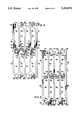
- FIGS. 4a, bare schematic diagram of a first preferred EDI intermembrane spacer (according to a third aspect of this invention) to be packed with particulates;
- FIG. 5is a schematic diagram of a second preferred EDI intermembrane spacer to be packed with particulates
- FIG. 6is a schematic diagram of a third preferred EDI intermembrane spacer to be packed with particulates
- FIGS. 7a, b, c and dare simplified, schematic diagram of a preferred strainer (according to a fourth aspect of this invention) for retaining at least part of ion exchange particulates in packed compartments of EDI stacks.
- FIG. 2there is indicated schematically a packed cell electrodialysis (electrodeionization) stack 11 in a preferred embodiment having cation selective membranes C, and anion selective membrane A, an anode E + and a cathode E - .
- Gaskets 16separate the stack into electrode compartments 4, deionizing compartment(s) 10, and concentrating compartment(s) 12.
- Generally stack 11will consist of many alternating membranes A and C and many alternating compartments 10 and 12, between one set of electrodes and electrode compartments.
- Influent fill conduit(s) 14communicates with deionization compartment(s) 10 by means of deionization compartment internal fill manifold(s) 15 and deionization compartment inlet fill channels 17.
- strainers 18for retaining ion exchange particulates in compartment 10 against fluid passing through said compartment.
- Said strainersmay for example take the form of screen, expanded plastic sheet, embossed plastic sheet, combs and the like.
- the plane of the screen, comb, or sheetmay be parallel, perpendicular, or at an angle to the direction of flow of fluid in compartment(s) 10.
- the apertures in said strainersmust be smaller than at least some of the ion exchange particulates but not necessarily smaller than all such particulates since any particulates retained by strainers 18 will retain smaller particulates. For example if the particulates are in the range of 20 to 50 U.S.
- strainers 18should be capable of retaining particulates of say, at least 30 mesh and larger (i.e. about 0.06 centimeters and larger).
- internal fill manifold(s) 15also communicates with effluent fill conduit(s) 19 which can recirculate none, part, or all of the influent slurry through control valve 21 and back to tank 22. Fluid leaving compartment(s) 10 through strainers 18 leaves the stack through internal manifolds 24 which communicate with conduits 23.
- Vessel 22contains a suspension of anion exchange particulates AX and cation exchange particulates CX in an appropriate fluid, for example water or aqueous solutions of sodium chloride or other solutes which prevent clumping of anion and cation resin particulates; or liquids which prevent said clumping as well as increase viscosity and/or density, such as glycerine, propylene glycol, or aqueous solutions thereof.
- an appropriate fluidfor example water or aqueous solutions of sodium chloride or other solutes which prevent clumping of anion and cation resin particulates; or liquids which prevent said clumping as well as increase viscosity and/or density, such as glycerine, propylene glycol, or aqueous solutions thereof.
- FIG. 2schematically illustrates process and apparatus in a preferred embodiment for packing an EDI apparatus with particulate ion exchangers.
- particulates AX and CXare suspended in the fluid in vessel 22 by means of agitator 25.
- Conduits 14 and 19, internal fill manifold(s) 15, pumping means (preferably, for example, a recessed impeller pump) 20are filled with appropriate fluid from vessel 22.
- pumping means 20When pumping means 20 is activated, the particulate suspension is drawn from vessel 22 and conveyed by influent fill conduit 14 to internal fill manifold 15. At least part of such suspension, as controlled by valve 21, passes through inlet channels 17 into compartment(s) 10.
- Fluid effluent from compartment(s) 10passes through strainers 18, internal manifolds 24, and is preferably recirculated by conduits 23 to vessel 22.
- fill conduits 14 and 19are closed off to hold the packed particulates in place.
- Liquid to be processedthen is pumped into internal manifold(s) 24 at one end of the stack only, passes through the first strainer(s) 18, compartment(s) 10, a second strainer(s) 18, a second internal manifold(s) 24 and out of the stack. (See FIG. 2 for key).
- This description of EDI operationis useful in describing the advantages of the present invention related to filling the EDI stack with particulates.
- the process and apparatus of FIG. 2, related to filling the EDI stack with particulates,has many advantages for EDI operation. For example:
- the size of the particulates AX and CXcan be varied along the flow path in compartment(s) 10.
- the first increment of particulatescan be of comparatively large size and easily retained by strainers 18, subsequent increments being smaller and the final increment again larger;
- the relative blend of AX and CX particulatescan be varied along the flow path.
- a multi-layered packinge.g. of alternating AX and CX particulates or the lower part of compartment 10 can contain such layered packing and the upper part randomly mixed particulates;
- the portion of the packing in compartment 10 which is the first to contact fluidcan have special properties, e.g. it can be non-ion exchange particulates or organic scavenging particulates even if such are poor electrolytic conductors or even electrical insulators.
- FIG. 2shows only the circuits applying to the deionization compartments. Obviously conduits, manifolds, and inlets and outlets are required to bring fluids into and out of the concentrate chamber(s) 12. Such chambers can also be packed with ion exchange particulates which need not be the same in size or distribution of AX and CX particulates. If compartments(s) 12 are also packed and are identical with compartment(s) 10, then the choice of the polarities of electrodes E - and E + is arbitrary, i.e. they can be interchanged as fully disclosed as one preferred embodiment in co-pending application Ser. No. 07/389,850 filed Aug. 3, 1989 and assigned to a common assignee.
- compartment(s) 12will become deionizing and compartment(s) 10 concentrating.
- the direction of passage of direct electric currentcan be changed for example once every 6 to 24 hours.
- Such periodcan be compensated for by utilizing a somewhat larger apparatus and/or product storage tanks or by auxiliary conventional ion exchange deionizers or all of the above.
- Such reversing type electrodeionization apparatusis particularly advantageous since the reversal tends to remove fouling and scaling materials from the membranes and particulates. It is further advantageous in that the rate of increase in electrical resistance of the stack due to the conversion (in anion selective membranes and anion exchange particulates) of quaternary ammonium groups to non-quaternary moieties is reduced.
- FIG. 2Many modifications of the process and apparatus in FIG. 2 can be made within the scope of the invention.
- an alternate preferred embodimentwould be to rotate the EDI stack 11 90 degrees so that stack components are vertical. This orientation will allow particulate containment in compartment 10(s) during downflow EDI operation.
- the upper strainers 18 and intermediate fill manifold 15can then be removed allowing particulate fill via the upper internal manifold 24.
- This simpler construction compared to that shown in FIG. 2can be traded off for various applications with the greater difficulties in filling a longer flow path and in structurally supporting the membrane areas adjacent to the internal manifold 24-compartment(s) 10 connection in the absence of a strainer support.
- FIG. 3is a simplified, schematic diagram of process and apparatus for removing exchange particulates from the electrodeionization apparatus of FIG. 2 and for cleaning, reactivating, and/or replacing some or all of such particulates.
- Suitable fluidis taken from vessel 22 (which contains no particulates) by pumping means 20 (preferably the same as in FIG. 2) through conduits 23, entering stack 11 through internal manifolds 24 and strainers 18, suspending and eventually removing ion exchange particulates out of compartment(s) 10 through channels 17, internal manifolds 15, and conduits 14 to bag filter(s) 25.
- Particulates (and gas, if any)are separated from the fluid at this point prior to recycle into tank 22.
- Such fluidmay be liquid (e.g., water) or mixed liquid-gas (e.g., water-air).
- the particulates returned to bag filter 25can then be cleaned of scale, for example with dilute acids or chelating agents, or of foulants, for example, with any de-fouling agent well known in conventional ion-exchange practice including enzymes.
- the particulatescan be recovered in bulk form, classified into AX and CX fractions and/or into fractions according to particle size. Broken beads or spheres can be rejected.
- the cleaned particulatescan be analyzed for degradation of properties by methods well known in the ion-exchange art and replaced if necessary.
- FIG. 4ashows schematically one preferred diluting chamber inter-membrane spacer 49 according to this invention.
- the spacer materialmay for example be any plastic or coated plastic which has suitable properties for the title apparatus and method. Examples of these properties are described below.
- the spacermay comprise for example any suitable plastic material. If the polymer or elastomer is hard then it is preferred that the surfaces (i.e. in the plane of FIG. 4) have a resilient layer or coating.
- 52bdesignates the peripheral structure of spacer 49. The peripheral structure provides mechanical support to parallel components above and below the plane of FIG.
- 52balso provides sufficient mechanical support so as to prevent its being blown outward by process pressure when held in such compression; 52b also provides sealing surfaces against adjacent membranes to prevent leakage to the outside or leakage into manifolds 69a,b, 70a,b.
- 52a and 52care vertical ribs in spacer 49; these provide mechanical support to components above and below (similar to 52a and c ) and support sealing surfaces between manifolds 56a-d and flow paths in concentrating spacers (not shown) on the other side of the adjacent membranes (also now shown).
- 62a and 62bindicate peripheral internal manifold holes communicating with cavities 58a and 58b resp.
- 66c and 66dindicate peripheral internal manifolds communicating with cavities 58c and 58d, resp.
- Cavities 58a and 58c on the one hand and 58b and 58d on the otherare separated from each other by optional supports 54a,b; 54a,b provide additional mechanical support to prevent 52b from being blown outwards by process pressures.
- Such supportsmay be straps which are only part of the thickness of spacer 49; full thickness straps which are slotted externally and/or internally to permit fluid flow between the respective cavities; screens or expanded plastic; or the like.
- 50designates a flow remixing width constrictor, in this case having intermediate internal manifolds 56a-d communicating with cavities 58a, 58b, 58c and 58d resp.
- strap supports 54a and 54b and constrictor 50are shown more or less exactly in the middle of spacer 49 they can in fact be at any appropriate position between peripheral manifolds 62a and 62b on one hand and 66c and 66d on the other.
- constrictor 50may be at the lower end of cavities 58c and d and rotated 90 degrees in which case the hydraulic flowpath may be from manifold 62a through cavities 58a and c (then e.g. constituting a single cavity), the cavities 58d and b (also then e.g.
- FIG. 4ashows a spacer having two joined flow paths 62a, 64a, 58a, 54a, 58c, 68c, and 66c on the one hand and 62b, 64b, 58b, 54b, 58d, 68d, and 66d on the other.
- Rib 52a and 52c and strap supports 54a and 54bare optional.
- width restrictor 50may be totally detached from spacer 49 and fastened (e.g.
- a single flowpath spacermay be made consisting say, of 62a, 64a, 58a, 54a, 58c 68c and 66c of FIG. 4a in which case rib 52a and 52c becomes an external gasket and only the left half of restrictor 50 is included.
- the spacer 49may be multiplied for example by a factor of two in width (in which case there would be eight cavities instead of 4, four strap supports 54 instead of two, two width restrictors 50 instead of one etc.) or by a factor of three or more.
- strap supports 54a and 54bare absent or permit passage of all the particulate ion exchanger used, the spacer 49 in connection with an alternate preferred embodiment referred to FIG. 2.
- supports 64a and 64bif present, must also permit passage of all the particulate ion exchanger but inserts 68c and 68d must capture at least some of the larger particulates as discussed above.
- the particulatescan be recovered from the compartment defined by spacer 49 by reversing the direction of flow as discussed in connection with FIG. 3.
- manifold holes 56a through d and entrance channels 60a through dcan be omitted.
- intermediate internal fill manifolds and channelsoffer several advantages:
- particulate exchangercan less easily by accident enter the process fluid transfer system and process fluid can less easily by accident enter the particulate exchanger transfer system.
- particulate exchangerenters and leaves the various cavities through intermediate manifolds 56a through d.
- Strainer-supports 64a, b and 68c, dshould then strain out at least the larger ion exchange particulates.
- cavities 58a and bwhich become fouled with particulates and/or colloids.
- Such cavitiescan be emptied through manifolds 62a and b (if supports 64a and b permit flow of all the particulate exchanger) by means of fluid flow through channels 60a and b while fluid flow through manifolds 66c and d is restricted or stopped by flow control means (e.g. one or more shut-off valves) in the external conduits communicating with manifolds 66c and d.
- flow control meanse.g. one or more shut-off valves
- a reverse direction of flow in cavities 58a and bcan instead flush the particulate exchangers out of channels 60a and b.
- constrictor 50or additional constrictor or half constrictor
- manifold holes 56a and b and channels 60a and bare located near manifold holes 62a and b so that only the contaminated particulate exchanger is removed.
- the upper portions of cavities 58a and bcontain for example an organic scavenging anion exchanger, activated carbon, silvered activated carbon, activated carbon containing other oligodynamic substances.
- cavities 58a and bare only about half filled with particulate exchanger then back flow from channels 60a and b, preferably from channels 60c and d can expand the packing sufficiently to permit the filtered material to be flushed out through manifolds 62a and b without removing the exchange particulates.
- the relevant intermediate channels 60are located near manifolds 62a and b so that only the fouled particulate exchanger packing is expanded. Such arrangement also minimizes the required amount of unfilled space in cavities 58a and b.
- Particulatesmay be classified or kept unclassified, as necessary for backwashing by using suspending fluids of appropriate densities (e.g. brines or aqueous solutions of glycerine and/or propylene glycol) or by wet screening.
- suspending fluids of appropriate densitiese.g. brines or aqueous solutions of glycerine and/or propylene glycol
- process fluidcan enter at 60a through d leaving at 62a, 62b, 66c and 66d respectively.
- spacer 49 of FIGS. 4a or brefers only to a diluting compartment. It can be easily modified within the spirit of the invention to provide the necessary flows into and/or out of parallel concentrating compartments.
- two of the channels in restrictor 50(say 60a and 60b) can be omitted in the spacer shown in the figure. It will be noted that when the spacer of FIG. 4a is turned end for end then inserts 64a and b will communicate with manifolds 70a and b and inserts 68c and d will communicate with intermediate manifolds 69a and b. Further channel 60c and d will communicate with intermediate manifolds 56a and b.
- Such inverted spacerbecomes a spacer for concentrating compartments.
- Such concentrating chambercan also be packed with particulate ion exchanger (particularly when reversal of the flow of electric current will be practiced) by the means previously discussed but at least should contain fluid permeable structure (e.g. woven or non-woven screen, expanded plastic, non-ion exchange, to enhance mass transfer to and from the membranes.
- fluid permeable structuree.g. woven or non-woven screen, expanded plastic, non-ion exchange
- FIG. 5illustrates a preferred spacer according to this invention having 8 particulate cavities and suitable, by appropriate orientation for both deionizing and concentrating particulate-filled compartments in an electrodeionization stack.
- the spaceris designed to transport ion exchange particles into and out of compartments 58a through d through intermediate channels 60c and d.
- Process fluidsmay enter the spacer through the latter channels and exit through peripheral manifolds 62a and b and 66c and d. Alternatively such fluids may enter at manifolds 62a and b resp.
- strainer supports 64a and bcan be omitted, exchange particles from cavities 58a and b then being transferred through manifolds 62a and b. In such case it will be preferred if process fluids enter through manifolds 62a and b at least.
- additional similar intermediate manifold holescan be used (double the number in FIG. 5) to facilitate external filling and unfilling of 58a-d. Such a system is shown in FIG. 6. Of course, if the concentrating compartment does not contain particulates, then the additional intermediate manifolds shown in FIG. 6 are unnecessary.
- FIG. 7illustrates schematically and in simplified form a preferred particulate strainer useful in this invention.
- Such strainersare readily permeated by fluid but at least not by the largest ion exchange particulates used.
- FIG. 7asuch strainer 64 is shown in the form of woven or non-woven screen or expanded plastic crimped toward the left-hand edge, the material left of such crimp integral with or bonded to the spacer 49. The portion of such strainer to the right of such crimp hangs free.
- FIGS. 7b and 7care cross-sections through section 7b of such strainer which may be defined as a water-permeable, particle-impermeable, for example foraminous flap valve.
- FIG. 7asuch strainer 64 is shown in the form of woven or non-woven screen or expanded plastic crimped toward the left-hand edge, the material left of such crimp integral with or bonded to the spacer 49. The portion of such strainer to the right of such crimp hangs free.
- FIG. 7bsuch flap valve is shown bonded at point p to the face of spacer 49 nearest cation selective membrane C.
- hydraulic resistancewill force such strainer valve down against anion selective membrane A, trapping said particulates in chamber 10.
- FIG. 7chydraulic resistance will force such strainer flap valve upward toward cation selective membrane C, permitting fluid and/or particulate exchanger to enter chamber 10.
- FIG. 7dis a schematic diagram of such a strainer flap valve in the form of a comb.
- the teeth of said combare shown occupying substantially all the area of the comb, such teeth could in fact extend only a short distance from the right hand edge of the comb.
- the combmay consist of one or more layers of plastic monofilaments, ribbons, or strips bonded together at the left hand edge in the drawing.
- the electrodeionization stack to be filledis comprised of a single electrical stage with two major hydraulic stages, each with a flow path length of about 33", each hydraulic stage containing five cell pairs.
- the overall stack component dimensions(membranes, spacers, etc.) are 18" wide ⁇ 40" long.
- the deionization compartment spacersare about 0.12 inches thick and in accordance with FIG. 5.
- the intermediate manifold holesare about 5/8 inch in diameter.
- the concentrating compartmentsare filled with plastic screen. In the concentrating spacer there are no channels between manifolds 56a-d and the flow path, and there are no strap supports 54a,b.
- the cation and anion flat sheet membranes which separate the diluting and concentrating spacerscontain manifold holes congruent with the manifold holes in spacer 49 (62a,b; 69a,b; 66c,d; 70a,b; 56a-d) except the cation membrane separating the two hydraulic stages has only manifolds congruent with 66c,d and 70a,b.
- a "resin fill" centrifugal pump with recessed impelleris then activated to establish a positive pressure in the ion depleting or diluting compartments of the stack.
- a backpressure of about 3.6 psigis imposed on the effluent from the diluting compartments to make certain that positive pressure compared to the concentrating compartments extends throughout the flow path (internal space) in the diluting compartment.
- the supply tank mixeris then activated at such a rate that the resin beads quickly rise into suspension at least above the "resin fill” pump suction connection located part way up the wall of the supply tank.
- the resin slurryis flowed by way of the eight intermediate manifolds (four from the bottom for the first major hydraulic stage and four from the bottom for the second) into the diluting compartments of the stack simultaneously.
- manifolds 56a and bservice cavities 58a and 58b (comprising the first minor hydraulic stage) by means of channels 60a and b as illustrated in FIG. 4a and manifolds 56c and d service cavities 58c and d (comprising the second minor hydraulic state).
- Water in the slurrypasses through the strainer-supports (screens) of the operating inlets and outlets of the diluting compartments (62a,b and 66c, d) and returns to the supply tank through appropriate valves and conduits.
- the stackis then connected for normal water desalting operation. After the excess NaCl from the fill slurry is flushed from the system, the stack is operated to produce about 2 megohm-cm water at the expected flow rate using 1230 microSiemens/cm ( ⁇ S/cm) feed water.
- the stackis disassembled and inspected. All diluting compartments are found to be substantially full of resin with negligible classification of the anion and cation resin beads.
- the same stackis similarly filled with three increments of a 0.67% slurry, and in a separate test with one increment of 2% slurry.
- the 2% slurry fillis completed in about 32 minutes. In both cases, the diluting compartments on inspection are observed to be substantially full of resin with negligible resin classification.
- the stackis similarly filled using a 0.33% resin slurry prepared with a solution made from 49% by vol. of propylene glycol and 56% ultra-filtered tap water. The fill operation is again completed with negligible classification of the resins.
- the EDI stackis pressurized and then ball valves on the intermediate manifolds 56a-d are opened simultaneously. Resin bead slurry exits through the intermediate manifolds. Initially, the stack inlet pressure is 20 psig and this is maintained throughout the unfilling.
- the resinis removed and recovered in a filter bag as the salt water carrier is recycled to the fill tank.
- resin removalis facilitated by starting and stopping the pump and by quickly opening and closing the ball valves on the intermediate manifold pipes.
- the electrodeionization stack of Examples 1 and 2is reassembled with 150 more or less identical cell pairs using the same resin type, NaCl concentration, and fill procedure and apparatus except that several additional 1800 mL resin bead segments are added to the fill tank as the stack substantially fills.
- the stackis then operated to desalt 1000 ⁇ S/cm NaCl feed to 0.4 megohm-cm product at the expected rate. Inspection of the stack after disassembly discloses the average diluting compartment is more than 90% full of resin with negligible classification of the resin beads.
- the electrodeionization stack of Example 3is unfilled using the same apparatus and procedure as used in Example 2. Inspection of the stack during disassembly discloses that 90% of the resin which had flowed into the stack has now been flowed out into the filter bags.
Landscapes
- Chemical & Material Sciences (AREA)
- Engineering & Computer Science (AREA)
- Water Supply & Treatment (AREA)
- Chemical Kinetics & Catalysis (AREA)
- Health & Medical Sciences (AREA)
- Urology & Nephrology (AREA)
- Organic Chemistry (AREA)
- Separation Using Semi-Permeable Membranes (AREA)
Abstract
Description
Claims (9)
Priority Applications (1)
| Application Number | Priority Date | Filing Date | Title |
|---|---|---|---|
| US07/866,782US5203976A (en) | 1990-03-19 | 1992-04-06 | Introducing and removing ion-exchange and other particulates rom an assembled electrodeionization stack |
Applications Claiming Priority (3)
| Application Number | Priority Date | Filing Date | Title |
|---|---|---|---|
| US07/495,513US5066375A (en) | 1990-03-19 | 1990-03-19 | Introducing and removing ion-exchange and other particulates from an assembled electrodeionization stack |
| US07/743,068US5120416A (en) | 1990-03-19 | 1991-08-09 | Introducing and removing ion-exchange and other particulates from an assembled electrodeionization stack |
| US07/866,782US5203976A (en) | 1990-03-19 | 1992-04-06 | Introducing and removing ion-exchange and other particulates rom an assembled electrodeionization stack |
Related Parent Applications (1)
| Application Number | Title | Priority Date | Filing Date |
|---|---|---|---|
| US07/743,068DivisionUS5120416A (en) | 1990-03-19 | 1991-08-09 | Introducing and removing ion-exchange and other particulates from an assembled electrodeionization stack |
Publications (1)
| Publication Number | Publication Date |
|---|---|
| US5203976Atrue US5203976A (en) | 1993-04-20 |
Family
ID=27414005
Family Applications (1)
| Application Number | Title | Priority Date | Filing Date |
|---|---|---|---|
| US07/866,782Expired - LifetimeUS5203976A (en) | 1990-03-19 | 1992-04-06 | Introducing and removing ion-exchange and other particulates rom an assembled electrodeionization stack |
Country Status (1)
| Country | Link |
|---|---|
| US (1) | US5203976A (en) |
Cited By (56)
| Publication number | Priority date | Publication date | Assignee | Title |
|---|---|---|---|---|
| US5512173A (en)* | 1993-04-21 | 1996-04-30 | Nippon Rensui Co. | Demineralization apparatus and cloth for packing diluting chamber of the demineralization apparatus |
| US5558753A (en)* | 1994-05-20 | 1996-09-24 | U.S. Filter/Ionpure, Inc. | Polarity reversal and double reversal electrodeionization apparatus and method |
| US5679229A (en)* | 1994-04-25 | 1997-10-21 | Ionics, Incorporated | Electrodialysis including filled cell electrodialysis (electrodeionization) |
| US5858191A (en)* | 1996-09-23 | 1999-01-12 | United States Filter Corporation | Electrodeionization apparatus and method |
| US5891328A (en)* | 1995-03-23 | 1999-04-06 | Ionics, Incorporated | Membrane-frame for processes including electrodialysis |
| US6187162B1 (en) | 1999-09-13 | 2001-02-13 | Leon Mir | Electrodeionization apparatus with scaling control |
| US6241867B1 (en) | 1999-09-13 | 2001-06-05 | Leon Mir | Electrodeionization apparatus and packing therefor |
| US6241866B1 (en) | 1999-09-13 | 2001-06-05 | Leon Mir | Electrodeionization apparatus with fixed ion exchange materials |
| US6254753B1 (en) | 1999-09-13 | 2001-07-03 | Leon Mir | High purity electrodeionization |
| US6284124B1 (en) | 1999-01-29 | 2001-09-04 | United States Filter Corporation | Electrodeionization apparatus and method |
| US6296751B1 (en) | 1999-09-13 | 2001-10-02 | Leon Mir | Electrodeionization apparatus with scaling control |
| US20030089609A1 (en)* | 2001-10-15 | 2003-05-15 | United States Filter Corporation | Apparatus for fluid purification and methods of manufacture and use thereof |
| US20030146090A1 (en)* | 2002-02-02 | 2003-08-07 | Mack Bernard R. | EDI and related stacks and method and apparatus for preparing such |
| US6607647B2 (en) | 2001-04-25 | 2003-08-19 | United States Filter Corporation | Electrodeionization apparatus with expanded conductive mesh electrode and method |
| US6649037B2 (en) | 2001-05-29 | 2003-11-18 | United States Filter Corporation | Electrodeionization apparatus and method |
| US20040035802A1 (en)* | 2000-07-10 | 2004-02-26 | Emery Nigel Philip | Electrodeionisation apparatus |
| US20040079700A1 (en)* | 2002-10-23 | 2004-04-29 | Jonathan Wood | Production of water for injection using reverse osmosis |
| US20040173535A1 (en)* | 2003-02-06 | 2004-09-09 | Zhejiang Omex Environmental Engineering, Ltd. | Serviceable electrodeionization apparatus and method for resin refill |
| US20050016932A1 (en)* | 2000-09-28 | 2005-01-27 | United States Filter Corporation | Electrodeionization device and methods of use |
| US20050103631A1 (en)* | 2003-11-13 | 2005-05-19 | United States Filter Corporation | Water treatment system and method |
| US20050103717A1 (en)* | 2003-11-13 | 2005-05-19 | United States Filter Corporation | Water treatment system and method |
| US20050103724A1 (en)* | 2003-11-13 | 2005-05-19 | United States Filter Corporation | Water treatment system and method |
| US20050103722A1 (en)* | 2003-11-13 | 2005-05-19 | United States Filter Corporation | Water treatment system and method |
| US20050103644A1 (en)* | 2003-11-13 | 2005-05-19 | United States Filter Corporation | Water treatment system and method |
| US20050103723A1 (en)* | 2003-11-13 | 2005-05-19 | United States Filter Corporation | Water treatment system and method |
| US20050103630A1 (en)* | 2003-11-13 | 2005-05-19 | United States Filter Corporation | Water treatment system and method |
| US20050103622A1 (en)* | 2003-11-13 | 2005-05-19 | United States Filter Corporation | Water treatment system and method |
| US20050221385A1 (en)* | 2000-11-07 | 2005-10-06 | Caliper Life Sciences, Inc. | Pressure based mobility shift assays |
| US20050263457A1 (en)* | 2004-05-27 | 2005-12-01 | Wilkins Frederick C | Water treatment system and process |
| US7105304B1 (en)* | 2000-11-07 | 2006-09-12 | Caliper Life Sciences, Inc. | Pressure-based mobility shift assays |
| US20060231495A1 (en)* | 2005-04-13 | 2006-10-19 | Usfilter Corporation | Regeneration of adsorption media within electrical purification apparatuses |
| US20060231406A1 (en)* | 2005-04-13 | 2006-10-19 | Usfilter Corporation | Regeneration of adsorption media within electrical purification apparatuses |
| US20060291839A1 (en)* | 2005-06-01 | 2006-12-28 | Zoccolante Gary V | Water treatment system and process |
| US20070284251A1 (en)* | 2006-06-13 | 2007-12-13 | Zuback Joseph E | Method and system for providing potable water |
| US20070295604A1 (en)* | 2006-06-23 | 2007-12-27 | Siemens Water Technologies Corporation | Electrically-driven separation apparatus |
| US20080067125A1 (en)* | 2006-09-20 | 2008-03-20 | Wilkins Frederick C | Method and apparatus for desalination |
| US20090118139A1 (en)* | 2000-11-07 | 2009-05-07 | Caliper Life Sciences, Inc. | Microfluidic method and system for enzyme inhibition activity screening |
| US7780833B2 (en) | 2005-07-26 | 2010-08-24 | John Hawkins | Electrochemical ion exchange with textured membranes and cartridge |
| US7959780B2 (en) | 2004-07-26 | 2011-06-14 | Emporia Capital Funding Llc | Textured ion exchange membranes |
| US20110180477A1 (en)* | 2008-04-03 | 2011-07-28 | Siemens Water Technologies Corp. | Low energy system and method of desalinating seawater |
| WO2012170192A1 (en) | 2011-06-10 | 2012-12-13 | Dow Global Technologies Llc | Method of assembly of an electrodeionization device including ion exchange spacer |
| US20130180858A1 (en)* | 2010-09-14 | 2013-07-18 | Organo Corporation | Electric device for producing deionized water |
| US8562803B2 (en) | 2005-10-06 | 2013-10-22 | Pionetics Corporation | Electrochemical ion exchange treatment of fluids |
| US8585882B2 (en) | 2007-11-30 | 2013-11-19 | Siemens Water Technologies Llc | Systems and methods for water treatment |
| US8671985B2 (en) | 2011-10-27 | 2014-03-18 | Pentair Residential Filtration, Llc | Control valve assembly |
| US8961770B2 (en) | 2011-10-27 | 2015-02-24 | Pentair Residential Filtration, Llc | Controller and method of operation of a capacitive deionization system |
| US9010361B2 (en) | 2011-10-27 | 2015-04-21 | Pentair Residential Filtration, Llc | Control valve assembly |
| US9023185B2 (en) | 2006-06-22 | 2015-05-05 | Evoqua Water Technologies Llc | Low scale potential water treatment |
| US9592472B2 (en) | 2006-06-13 | 2017-03-14 | Evoqua Water Technologies Llc | Method and system for irrigation |
| US9637397B2 (en) | 2011-10-27 | 2017-05-02 | Pentair Residential Filtration, Llc | Ion removal using a capacitive deionization system |
| US9695070B2 (en) | 2011-10-27 | 2017-07-04 | Pentair Residential Filtration, Llc | Regeneration of a capacitive deionization system |
| US9757695B2 (en) | 2015-01-03 | 2017-09-12 | Pionetics Corporation | Anti-scale electrochemical apparatus with water-splitting ion exchange membrane |
| US10252923B2 (en) | 2006-06-13 | 2019-04-09 | Evoqua Water Technologies Llc | Method and system for water treatment |
| US10625211B2 (en) | 2006-06-13 | 2020-04-21 | Evoqua Water Technologies Llc | Method and system for water treatment |
| US11820689B2 (en) | 2017-08-21 | 2023-11-21 | Evoqua Water Technologies Llc | Treatment of saline water for agricultural and potable use |
| US12180103B2 (en) | 2017-08-21 | 2024-12-31 | Evoqua Water Technologies Llc | Treatment of saline water for agricultural and potable use and for generation of disinfectant solution |
Citations (4)
| Publication number | Priority date | Publication date | Assignee | Title |
|---|---|---|---|---|
| US4871431A (en)* | 1988-07-11 | 1989-10-03 | Ionics, Incorporated | Apparatus for the removal of dissolved solids from liquids using bipolar membranes |
| US5026465A (en)* | 1989-08-03 | 1991-06-25 | Ionics, Incorporated | Electrodeionization polarity reversal apparatus and process |
| US5066375A (en)* | 1990-03-19 | 1991-11-19 | Ionics, Incorporated | Introducing and removing ion-exchange and other particulates from an assembled electrodeionization stack |
| US5120416A (en)* | 1990-03-19 | 1992-06-09 | Ionics, Incorporated | Introducing and removing ion-exchange and other particulates from an assembled electrodeionization stack |
- 1992
- 1992-04-06USUS07/866,782patent/US5203976A/ennot_activeExpired - Lifetime
Patent Citations (4)
| Publication number | Priority date | Publication date | Assignee | Title |
|---|---|---|---|---|
| US4871431A (en)* | 1988-07-11 | 1989-10-03 | Ionics, Incorporated | Apparatus for the removal of dissolved solids from liquids using bipolar membranes |
| US5026465A (en)* | 1989-08-03 | 1991-06-25 | Ionics, Incorporated | Electrodeionization polarity reversal apparatus and process |
| US5066375A (en)* | 1990-03-19 | 1991-11-19 | Ionics, Incorporated | Introducing and removing ion-exchange and other particulates from an assembled electrodeionization stack |
| US5120416A (en)* | 1990-03-19 | 1992-06-09 | Ionics, Incorporated | Introducing and removing ion-exchange and other particulates from an assembled electrodeionization stack |
Cited By (107)
| Publication number | Priority date | Publication date | Assignee | Title |
|---|---|---|---|---|
| US5512173A (en)* | 1993-04-21 | 1996-04-30 | Nippon Rensui Co. | Demineralization apparatus and cloth for packing diluting chamber of the demineralization apparatus |
| US5948230A (en)* | 1994-04-25 | 1999-09-07 | Ionics, Incorporated | Electrodialysis including filled cell electrodialysis (Electrodeionization) |
| US6126805A (en)* | 1994-04-25 | 2000-10-03 | Ionics, Incorporated | Electrodialysis including filled cell electrodialysis (electrodeionization) |
| US5679228A (en)* | 1994-04-25 | 1997-10-21 | Ionics, Incorporated | Electrodialysis including filled cell electrodialysis (electrodeionization) |
| US5679229A (en)* | 1994-04-25 | 1997-10-21 | Ionics, Incorporated | Electrodialysis including filled cell electrodialysis (electrodeionization) |
| US5814197A (en)* | 1994-04-25 | 1998-09-29 | Ionics, Incorporated | Electrodialysis including filled cell electrodialysis (electrodeionization) |
| US5736023A (en)* | 1994-05-20 | 1998-04-07 | U.S. Filter/Ionpure, Inc. | Polarity reversal and double reversal electrodeionization apparatus and method |
| US5558753A (en)* | 1994-05-20 | 1996-09-24 | U.S. Filter/Ionpure, Inc. | Polarity reversal and double reversal electrodeionization apparatus and method |
| US5891328A (en)* | 1995-03-23 | 1999-04-06 | Ionics, Incorporated | Membrane-frame for processes including electrodialysis |
| US6117297A (en)* | 1995-03-23 | 2000-09-12 | Ionics, Incorporated | Electrodialysis apparatus |
| US5858191A (en)* | 1996-09-23 | 1999-01-12 | United States Filter Corporation | Electrodeionization apparatus and method |
| US5868915A (en)* | 1996-09-23 | 1999-02-09 | United States Filter Corporation | Electrodeionization apparatus and method |
| US6284124B1 (en) | 1999-01-29 | 2001-09-04 | United States Filter Corporation | Electrodeionization apparatus and method |
| US6514398B2 (en) | 1999-01-29 | 2003-02-04 | United States Filter Corporation | Electrodeionization apparatus and method |
| US6312577B1 (en) | 1999-01-29 | 2001-11-06 | United State Filter Corporation | Continuous electrodeionization apparatus and method |
| US6241866B1 (en) | 1999-09-13 | 2001-06-05 | Leon Mir | Electrodeionization apparatus with fixed ion exchange materials |
| US6187162B1 (en) | 1999-09-13 | 2001-02-13 | Leon Mir | Electrodeionization apparatus with scaling control |
| US6296751B1 (en) | 1999-09-13 | 2001-10-02 | Leon Mir | Electrodeionization apparatus with scaling control |
| US6254753B1 (en) | 1999-09-13 | 2001-07-03 | Leon Mir | High purity electrodeionization |
| US6241867B1 (en) | 1999-09-13 | 2001-06-05 | Leon Mir | Electrodeionization apparatus and packing therefor |
| US7279083B2 (en) | 2000-07-10 | 2007-10-09 | Vws (Uk) Ltd | Electrodeionisation apparatus |
| US20040035802A1 (en)* | 2000-07-10 | 2004-02-26 | Emery Nigel Philip | Electrodeionisation apparatus |
| US7147785B2 (en) | 2000-09-28 | 2006-12-12 | Usfilter Corporation | Electrodeionization device and methods of use |
| US20050016932A1 (en)* | 2000-09-28 | 2005-01-27 | United States Filter Corporation | Electrodeionization device and methods of use |
| US20090118139A1 (en)* | 2000-11-07 | 2009-05-07 | Caliper Life Sciences, Inc. | Microfluidic method and system for enzyme inhibition activity screening |
| US20050221385A1 (en)* | 2000-11-07 | 2005-10-06 | Caliper Life Sciences, Inc. | Pressure based mobility shift assays |
| US7105304B1 (en)* | 2000-11-07 | 2006-09-12 | Caliper Life Sciences, Inc. | Pressure-based mobility shift assays |
| US6607647B2 (en) | 2001-04-25 | 2003-08-19 | United States Filter Corporation | Electrodeionization apparatus with expanded conductive mesh electrode and method |
| US6649037B2 (en) | 2001-05-29 | 2003-11-18 | United States Filter Corporation | Electrodeionization apparatus and method |
| US20040089551A1 (en)* | 2001-05-29 | 2004-05-13 | United States Filter Corporation | Electrodeionization apparatus and method |
| US6824662B2 (en) | 2001-05-29 | 2004-11-30 | Usfilter Corporation | Electrodeionization apparatus and method |
| US20080105548A1 (en)* | 2001-10-15 | 2008-05-08 | Siemens Water Technologies Corp. | Apparatus for fluid purification and methods of manufacture and use thereof |
| US20030089609A1 (en)* | 2001-10-15 | 2003-05-15 | United States Filter Corporation | Apparatus for fluid purification and methods of manufacture and use thereof |
| US7572359B2 (en) | 2001-10-15 | 2009-08-11 | Siemens Water Technologies Holding Corp. | Apparatus for fluid purification and methods of manufacture and use thereof |
| US8101058B2 (en) | 2001-10-15 | 2012-01-24 | Siemens Industry, Inc. | Apparatus for fluid purification |
| US8721862B2 (en) | 2001-10-15 | 2014-05-13 | Evoqua Water Technologies Llc | Apparatus for fluid purification and methods of manufacture and use thereof |
| US20030146090A1 (en)* | 2002-02-02 | 2003-08-07 | Mack Bernard R. | EDI and related stacks and method and apparatus for preparing such |
| US7094325B2 (en) | 2002-02-02 | 2006-08-22 | Ionics, Incorporated | EDI and related stacks and method and apparatus for preparing such |
| US7501061B2 (en) | 2002-10-23 | 2009-03-10 | Siemens Water Technologies Holding Corp. | Production of water for injection using reverse osmosis |
| US7371319B2 (en) | 2002-10-23 | 2008-05-13 | Siemens Water Technologies Holding Corp. | Production of water for injection using reverse osmosis |
| US20050121388A1 (en)* | 2002-10-23 | 2005-06-09 | Usfilter Corporation | Production of water for injection using reverse osmosis |
| US20040079700A1 (en)* | 2002-10-23 | 2004-04-29 | Jonathan Wood | Production of water for injection using reverse osmosis |
| WO2004085042A1 (en)* | 2003-02-06 | 2004-10-07 | Zhejiang Omex Environmental Engineering Ltd. | Serviceable electrodeionization apparatus and method for resin refill |
| US20040173535A1 (en)* | 2003-02-06 | 2004-09-09 | Zhejiang Omex Environmental Engineering, Ltd. | Serviceable electrodeionization apparatus and method for resin refill |
| US7604725B2 (en) | 2003-11-13 | 2009-10-20 | Siemens Water Technologies Holding Corp. | Water treatment system and method |
| US20050103724A1 (en)* | 2003-11-13 | 2005-05-19 | United States Filter Corporation | Water treatment system and method |
| US8114260B2 (en) | 2003-11-13 | 2012-02-14 | Siemens Industry, Inc. | Water treatment system and method |
| US7083733B2 (en) | 2003-11-13 | 2006-08-01 | Usfilter Corporation | Water treatment system and method |
| US20110120886A1 (en)* | 2003-11-13 | 2011-05-26 | Siemens Water Technologies Holding Corp. | Water treatment system and method |
| US20110120953A1 (en)* | 2003-11-13 | 2011-05-26 | Siemens Water Technologies Holding Corp. | Water treatment system and method |
| US8894834B2 (en) | 2003-11-13 | 2014-11-25 | Evoqua Water Technologies Llc | Water treatment system and method |
| US8864971B2 (en) | 2003-11-13 | 2014-10-21 | Evoqua Water Technologies Llc | Water treatment system and method |
| US7862700B2 (en) | 2003-11-13 | 2011-01-04 | Siemens Water Technologies Holding Corp. | Water treatment system and method |
| US20050103631A1 (en)* | 2003-11-13 | 2005-05-19 | United States Filter Corporation | Water treatment system and method |
| US20050103622A1 (en)* | 2003-11-13 | 2005-05-19 | United States Filter Corporation | Water treatment system and method |
| US20050103630A1 (en)* | 2003-11-13 | 2005-05-19 | United States Filter Corporation | Water treatment system and method |
| US7846340B2 (en) | 2003-11-13 | 2010-12-07 | Siemens Water Technologies Corp. | Water treatment system and method |
| US20050103723A1 (en)* | 2003-11-13 | 2005-05-19 | United States Filter Corporation | Water treatment system and method |
| US20050103644A1 (en)* | 2003-11-13 | 2005-05-19 | United States Filter Corporation | Water treatment system and method |
| US7563351B2 (en) | 2003-11-13 | 2009-07-21 | Siemens Water Technologies Holding Corp. | Water treatment system and method |
| US20050103722A1 (en)* | 2003-11-13 | 2005-05-19 | United States Filter Corporation | Water treatment system and method |
| US7582198B2 (en) | 2003-11-13 | 2009-09-01 | Siemens Water Technologies Holding Corp. | Water treatment system and method |
| US20050103717A1 (en)* | 2003-11-13 | 2005-05-19 | United States Filter Corporation | Water treatment system and method |
| US8377279B2 (en) | 2003-11-13 | 2013-02-19 | Siemens Industry, Inc. | Water treatment system and method |
| US8658043B2 (en) | 2003-11-13 | 2014-02-25 | Siemens Water Technologies Llc | Water treatment system and method |
| US7481929B2 (en) | 2004-05-27 | 2009-01-27 | Siemens Water Technologies Holding Corp. | Water treatment system |
| US7329358B2 (en) | 2004-05-27 | 2008-02-12 | Siemens Water Technologies Holding Corp. | Water treatment process |
| US20050263457A1 (en)* | 2004-05-27 | 2005-12-01 | Wilkins Frederick C | Water treatment system and process |
| US7959780B2 (en) | 2004-07-26 | 2011-06-14 | Emporia Capital Funding Llc | Textured ion exchange membranes |
| US7658828B2 (en) | 2005-04-13 | 2010-02-09 | Siemens Water Technologies Holding Corp. | Regeneration of adsorption media within electrical purification apparatuses |
| US20060231495A1 (en)* | 2005-04-13 | 2006-10-19 | Usfilter Corporation | Regeneration of adsorption media within electrical purification apparatuses |
| US20060231406A1 (en)* | 2005-04-13 | 2006-10-19 | Usfilter Corporation | Regeneration of adsorption media within electrical purification apparatuses |
| US20060291839A1 (en)* | 2005-06-01 | 2006-12-28 | Zoccolante Gary V | Water treatment system and process |
| US8045849B2 (en) | 2005-06-01 | 2011-10-25 | Siemens Industry, Inc. | Water treatment system and process |
| US8293085B2 (en) | 2005-07-26 | 2012-10-23 | Pionetics Corporation | Cartridge having textured membrane |
| US7780833B2 (en) | 2005-07-26 | 2010-08-24 | John Hawkins | Electrochemical ion exchange with textured membranes and cartridge |
| US9090493B2 (en) | 2005-10-06 | 2015-07-28 | Pionetics Corporation | Electrochemical ion exchange treatment of fluids |
| US8562803B2 (en) | 2005-10-06 | 2013-10-22 | Pionetics Corporation | Electrochemical ion exchange treatment of fluids |
| US10625211B2 (en) | 2006-06-13 | 2020-04-21 | Evoqua Water Technologies Llc | Method and system for water treatment |
| US10252923B2 (en) | 2006-06-13 | 2019-04-09 | Evoqua Water Technologies Llc | Method and system for water treatment |
| US9592472B2 (en) | 2006-06-13 | 2017-03-14 | Evoqua Water Technologies Llc | Method and system for irrigation |
| US20070284251A1 (en)* | 2006-06-13 | 2007-12-13 | Zuback Joseph E | Method and system for providing potable water |
| US9023185B2 (en) | 2006-06-22 | 2015-05-05 | Evoqua Water Technologies Llc | Low scale potential water treatment |
| US9586842B2 (en) | 2006-06-22 | 2017-03-07 | Evoqua Water Technologies Llc | Low scale potential water treatment |
| US7820024B2 (en) | 2006-06-23 | 2010-10-26 | Siemens Water Technologies Corp. | Electrically-driven separation apparatus |
| US20070295604A1 (en)* | 2006-06-23 | 2007-12-27 | Siemens Water Technologies Corporation | Electrically-driven separation apparatus |
| US7744760B2 (en) | 2006-09-20 | 2010-06-29 | Siemens Water Technologies Corp. | Method and apparatus for desalination |
| US20080067125A1 (en)* | 2006-09-20 | 2008-03-20 | Wilkins Frederick C | Method and apparatus for desalination |
| US8182693B2 (en) | 2006-09-20 | 2012-05-22 | Siemens Industry, Inc. | Method and apparatus for desalination |
| US9011660B2 (en) | 2007-11-30 | 2015-04-21 | Evoqua Water Technologies Llc | Systems and methods for water treatment |
| US8585882B2 (en) | 2007-11-30 | 2013-11-19 | Siemens Water Technologies Llc | Systems and methods for water treatment |
| US9637400B2 (en) | 2007-11-30 | 2017-05-02 | Evoqua Water Technologies Llc | Systems and methods for water treatment |
| US20110180477A1 (en)* | 2008-04-03 | 2011-07-28 | Siemens Water Technologies Corp. | Low energy system and method of desalinating seawater |
| US20130180858A1 (en)* | 2010-09-14 | 2013-07-18 | Organo Corporation | Electric device for producing deionized water |
| US9023184B2 (en)* | 2010-09-14 | 2015-05-05 | Organo Corporation | Electric device for producing deionized water |
| US8834663B2 (en) | 2011-06-10 | 2014-09-16 | Dow Global Technologies Llc | Electrodeionization device including ion exchange spacer and method of assembly |
| WO2012170192A1 (en) | 2011-06-10 | 2012-12-13 | Dow Global Technologies Llc | Method of assembly of an electrodeionization device including ion exchange spacer |
| US9637397B2 (en) | 2011-10-27 | 2017-05-02 | Pentair Residential Filtration, Llc | Ion removal using a capacitive deionization system |
| US8961770B2 (en) | 2011-10-27 | 2015-02-24 | Pentair Residential Filtration, Llc | Controller and method of operation of a capacitive deionization system |
| US9695070B2 (en) | 2011-10-27 | 2017-07-04 | Pentair Residential Filtration, Llc | Regeneration of a capacitive deionization system |
| US9903485B2 (en) | 2011-10-27 | 2018-02-27 | Pentair Residential Filtration, Llc | Control valve assembly |
| US9010361B2 (en) | 2011-10-27 | 2015-04-21 | Pentair Residential Filtration, Llc | Control valve assembly |
| US8671985B2 (en) | 2011-10-27 | 2014-03-18 | Pentair Residential Filtration, Llc | Control valve assembly |
| US9757695B2 (en) | 2015-01-03 | 2017-09-12 | Pionetics Corporation | Anti-scale electrochemical apparatus with water-splitting ion exchange membrane |
| US11820689B2 (en) | 2017-08-21 | 2023-11-21 | Evoqua Water Technologies Llc | Treatment of saline water for agricultural and potable use |
| US12180103B2 (en) | 2017-08-21 | 2024-12-31 | Evoqua Water Technologies Llc | Treatment of saline water for agricultural and potable use and for generation of disinfectant solution |
| US12227442B2 (en) | 2017-08-21 | 2025-02-18 | Evoqua Water Technologies Llc | Treatment of saline water for agricultural and potable use |
Similar Documents
| Publication | Publication Date | Title |
|---|---|---|
| US5203976A (en) | Introducing and removing ion-exchange and other particulates rom an assembled electrodeionization stack | |
| US5066375A (en) | Introducing and removing ion-exchange and other particulates from an assembled electrodeionization stack | |
| US5120416A (en) | Introducing and removing ion-exchange and other particulates from an assembled electrodeionization stack | |
| EP0874689B1 (en) | Electrodeionization apparatus having geometric arrangement of ion exchange material | |
| EP0660747B1 (en) | Modules for electrodeionization apparatus | |
| US7662267B2 (en) | Device and method for electrodialysis | |
| US6423205B1 (en) | Electric deionization apparatus | |
| US6187162B1 (en) | Electrodeionization apparatus with scaling control | |
| US8652315B2 (en) | Electrodeionization method and device with hydrodynamic flow splitting | |
| US20070051684A1 (en) | Sparse media edi apparatus and method | |
| MXPA01005250A (en) | Method and apparatus for electrodeionization of water using mixed bed and single phase ion exchange materials in diluting compartments. | |
| CA2148320A1 (en) | Electrochemical deionisation | |
| US7094325B2 (en) | EDI and related stacks and method and apparatus for preparing such | |
| WO1997046491A1 (en) | Process for producing deionized water by electrical deionization technique | |
| JPH08150393A (en) | Production of deionized water by electrolytic deionization method | |
| WO2014206381A1 (en) | The asymmetric ion-exchange membrane and use thereof | |
| CN220564436U (en) | Electrochemical auxiliary ion exchange water treatment device with electrochemical cells arranged in series | |
| HK1017292B (en) | Electrodeionization apparatus having geometric arrangement of ion exchange material | |
| MXPA98005620A (en) | Electrodesioning device that has a settlement or assembly of io exchange material |
Legal Events
| Date | Code | Title | Description |
|---|---|---|---|
| STCF | Information on status: patent grant | Free format text:PATENTED CASE | |
| FEPP | Fee payment procedure | Free format text:PAYOR NUMBER ASSIGNED (ORIGINAL EVENT CODE: ASPN); ENTITY STATUS OF PATENT OWNER: LARGE ENTITY | |
| FPAY | Fee payment | Year of fee payment:4 | |
| FPAY | Fee payment | Year of fee payment:8 | |
| FEPP | Fee payment procedure | Free format text:PAYER NUMBER DE-ASSIGNED (ORIGINAL EVENT CODE: RMPN); ENTITY STATUS OF PATENT OWNER: LARGE ENTITY Free format text:PAYOR NUMBER ASSIGNED (ORIGINAL EVENT CODE: ASPN); ENTITY STATUS OF PATENT OWNER: LARGE ENTITY | |
| AS | Assignment | Owner name:UBS AG, STAMFORD BRANCH AS COLLATERAL AGENT, CONNE Free format text:;ASSIGNOR:IONICS, INCORPORATED;REEL/FRAME:015000/0654 Effective date:20040213 Owner name:UBS AG, STAMFORD BRANCH AS COLLATERAL AGENT,CONNEC Free format text:SEE 015083/0722 CORRECTION OF REC. DATE;ASSIGNOR:IONICS, INCORPORATED;REEL/FRAME:015000/0654 Effective date:20040213 | |
| AS | Assignment | Owner name:UBS AG, STAMFORD BRANCH AS COLLATERAL AGENT, CONNE Free format text:SECURITY AGREEMENT;ASSIGNOR:IONICS, INCORPORATED;REEL/FRAME:015083/0722 Effective date:20040213 Owner name:UBS AG, STAMFORD BRANCH AS COLLATERAL AGENT,CONNEC Free format text:SECURITY AGREEMENT;ASSIGNOR:IONICS, INCORPORATED;REEL/FRAME:015083/0722 Effective date:20040213 | |
| FPAY | Fee payment | Year of fee payment:12 |