US5203769A - Medical device valving mechanism - Google Patents
Medical device valving mechanismDownload PDFInfo
- Publication number
- US5203769A US5203769AUS07/660,356US66035691AUS5203769AUS 5203769 AUS5203769 AUS 5203769AUS 66035691 AUS66035691 AUS 66035691AUS 5203769 AUS5203769 AUS 5203769A
- Authority
- US
- United States
- Prior art keywords
- rotor
- valve body
- valve
- passageway
- fluid
- Prior art date
- Legal status (The legal status is an assumption and is not a legal conclusion. Google has not performed a legal analysis and makes no representation as to the accuracy of the status listed.)
- Expired - Fee Related
Links
- 230000007246mechanismEffects0.000titleclaimsabstractdescription42
- 239000012530fluidSubstances0.000claimsabstractdescription84
- 210000003813thumbAnatomy0.000claimsabstractdescription35
- 238000004891communicationMethods0.000claimsabstractdescription18
- 239000002991molded plasticSubstances0.000claimsabstractdescription13
- 238000003780insertionMethods0.000claimsabstractdescription7
- 230000037431insertionEffects0.000claimsabstractdescription7
- 210000003811fingerAnatomy0.000claimsdescription26
- 239000000463materialSubstances0.000claimsdescription5
- 230000006641stabilisationEffects0.000claimsdescription3
- 238000011105stabilizationMethods0.000claimsdescription3
- 230000009977dual effectEffects0.000description6
- 239000004033plasticSubstances0.000description6
- 229920003023plasticPolymers0.000description6
- 210000002445nippleAnatomy0.000description5
- 238000000034methodMethods0.000description4
- -1polypropylenePolymers0.000description2
- 239000004677NylonSubstances0.000description1
- 239000004698PolyethyleneSubstances0.000description1
- 239000004743PolypropyleneSubstances0.000description1
- 239000004809TeflonSubstances0.000description1
- 229920006362Teflon®Polymers0.000description1
- 230000009471actionEffects0.000description1
- 238000013459approachMethods0.000description1
- 230000008901benefitEffects0.000description1
- 210000001124body fluidAnatomy0.000description1
- 239000010839body fluidSubstances0.000description1
- 238000011161developmentMethods0.000description1
- 230000000694effectsEffects0.000description1
- 230000003993interactionEffects0.000description1
- 238000007443liposuctionMethods0.000description1
- 239000002184metalSubstances0.000description1
- 229920001778nylonPolymers0.000description1
- 239000004417polycarbonateSubstances0.000description1
- 229920000515polycarbonatePolymers0.000description1
- 229920000573polyethylenePolymers0.000description1
- 229920001155polypropylenePolymers0.000description1
- 230000008569processEffects0.000description1
Images


Classifications
- A—HUMAN NECESSITIES
- A61—MEDICAL OR VETERINARY SCIENCE; HYGIENE
- A61M—DEVICES FOR INTRODUCING MEDIA INTO, OR ONTO, THE BODY; DEVICES FOR TRANSDUCING BODY MEDIA OR FOR TAKING MEDIA FROM THE BODY; DEVICES FOR PRODUCING OR ENDING SLEEP OR STUPOR
- A61M39/00—Tubes, tube connectors, tube couplings, valves, access sites or the like, specially adapted for medical use
- A61M39/22—Valves or arrangement of valves
- A61M39/223—Multiway valves
- A—HUMAN NECESSITIES
- A61—MEDICAL OR VETERINARY SCIENCE; HYGIENE
- A61B—DIAGNOSIS; SURGERY; IDENTIFICATION
- A61B18/00—Surgical instruments, devices or methods for transferring non-mechanical forms of energy to or from the body
- A61B18/04—Surgical instruments, devices or methods for transferring non-mechanical forms of energy to or from the body by heating
- A61B18/12—Surgical instruments, devices or methods for transferring non-mechanical forms of energy to or from the body by heating by passing a current through the tissue to be heated, e.g. high-frequency current
- A61B18/14—Probes or electrodes therefor
- A61B18/1482—Probes or electrodes therefor having a long rigid shaft for accessing the inner body transcutaneously in minimal invasive surgery, e.g. laparoscopy
- A—HUMAN NECESSITIES
- A61—MEDICAL OR VETERINARY SCIENCE; HYGIENE
- A61B—DIAGNOSIS; SURGERY; IDENTIFICATION
- A61B10/00—Instruments for taking body samples for diagnostic purposes; Other methods or instruments for diagnosis, e.g. for vaccination diagnosis, sex determination or ovulation-period determination; Throat striking implements
- A61B10/02—Instruments for taking cell samples or for biopsy
- A61B10/0233—Pointed or sharp biopsy instruments
- A61B10/0283—Pointed or sharp biopsy instruments with vacuum aspiration, e.g. caused by retractable plunger or by connected syringe
- A—HUMAN NECESSITIES
- A61—MEDICAL OR VETERINARY SCIENCE; HYGIENE
- A61M—DEVICES FOR INTRODUCING MEDIA INTO, OR ONTO, THE BODY; DEVICES FOR TRANSDUCING BODY MEDIA OR FOR TAKING MEDIA FROM THE BODY; DEVICES FOR PRODUCING OR ENDING SLEEP OR STUPOR
- A61M1/00—Suction or pumping devices for medical purposes; Devices for carrying-off, for treatment of, or for carrying-over, body-liquids; Drainage systems
- A61M1/71—Suction drainage systems
- A61M1/74—Suction control
- A61M1/741—Suction control with means for varying suction manually
- A61M1/7411—Suction control with means for varying suction manually by changing the size of a vent
- A—HUMAN NECESSITIES
- A61—MEDICAL OR VETERINARY SCIENCE; HYGIENE
- A61M—DEVICES FOR INTRODUCING MEDIA INTO, OR ONTO, THE BODY; DEVICES FOR TRANSDUCING BODY MEDIA OR FOR TAKING MEDIA FROM THE BODY; DEVICES FOR PRODUCING OR ENDING SLEEP OR STUPOR
- A61M1/00—Suction or pumping devices for medical purposes; Devices for carrying-off, for treatment of, or for carrying-over, body-liquids; Drainage systems
- A61M1/71—Suction drainage systems
- A61M1/77—Suction-irrigation systems
- A61M1/772—Suction-irrigation systems operating alternately
- A—HUMAN NECESSITIES
- A61—MEDICAL OR VETERINARY SCIENCE; HYGIENE
- A61M—DEVICES FOR INTRODUCING MEDIA INTO, OR ONTO, THE BODY; DEVICES FOR TRANSDUCING BODY MEDIA OR FOR TAKING MEDIA FROM THE BODY; DEVICES FOR PRODUCING OR ENDING SLEEP OR STUPOR
- A61M1/00—Suction or pumping devices for medical purposes; Devices for carrying-off, for treatment of, or for carrying-over, body-liquids; Drainage systems
- A61M1/71—Suction drainage systems
- A61M1/77—Suction-irrigation systems
- A61M1/774—Handpieces specially adapted for providing suction as well as irrigation, either simultaneously or independently
- Y—GENERAL TAGGING OF NEW TECHNOLOGICAL DEVELOPMENTS; GENERAL TAGGING OF CROSS-SECTIONAL TECHNOLOGIES SPANNING OVER SEVERAL SECTIONS OF THE IPC; TECHNICAL SUBJECTS COVERED BY FORMER USPC CROSS-REFERENCE ART COLLECTIONS [XRACs] AND DIGESTS
- Y10—TECHNICAL SUBJECTS COVERED BY FORMER USPC
- Y10S—TECHNICAL SUBJECTS COVERED BY FORMER USPC CROSS-REFERENCE ART COLLECTIONS [XRACs] AND DIGESTS
- Y10S604/00—Surgery
- Y10S604/902—Suction wands
Definitions
- the present inventionrelates to medical device valving mechanisms and handheld lavages and more particularly to the provision of a valve mechanism which may be held securely in one hand and operated by the thumb of that hand to open and close one or more valve passageways.
- the medical device valving mechanism of the present inventioncomprises an elongated valve body molded to have a longitudinal extending body shaped to be gripped and securely held in a user's hand leaving the hand's thumb free for valve operational movement.
- the valve bodyprovides at least one passageway extending longitudinal therethrough, and also provides a cylindrical opening or rotor bore extending transversely therethrough and intercepting the at least one passageway.
- a cylindrical molded plastic, one-piece rotoris provided for snug, slidable and rotational insertion into the cylindrical opening to block the said at least one passageway, the rotor being rotatable about its axis between valve opening and valve closing positions.
- the rotorhas at least one transaxially extending passageway therethrough which opens the at least one fluid passageway through the valve body when the rotor is in its valve opening position and which closes the at least one fluid passageway when the rotor is in its valve closing position.
- the valving mechanismalso comprises thumb-actuated means connected to the rotor for rotating the rotor between its positions, the actuating means being disposed above the valve body and the rotor for convenient thumb movement of the rotor.
- Connected to the valve body in fluid communication with at least one fluid passagewayis a conduit piece that channels and directs the flow of fluid leaving or entering the valve body.
- the conduit piececan be curved with respect to the valve body to extend either upward, downward, or sideways.
- the conduit piececan be divided into two or more fluid conduit portions for use with dual valves, and can also extend along a complex curve to direct fluid flow both downward and sideways with respect to the valve body.
- the conduit piececan be attached to the valve body as an integrally molded piece or separately formed as a snap-on piece that connects in fluid tight communication with the valve body.
- the valve body of the present inventionis preferably molded to have a forward bottom portion shaped to be gripped by the index finger of one hand and a rearward bottom portion shaped to be gripped by the middle finger of the hand with a depending transverse bottom portion between the forward and rearward portions.
- the middle transverse bottom portionis preferably directly below the cylindrical opening which holds the rotor to be disposed partially between the index and middle finger for stabilization.
- the rearward bottom portionis preferably transversely recessed to provide a comfortable gripping surface.
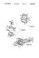
- FIG. 1is a perspective view of the valving mechanism of the present invention showing the mechanism held by one hand with the thumb of the hand controlling the valve rotor;
- FIG. 2is a longitudinal sectional view of the mechanism of FIG. 1;
- FIG. 3is a sectional view taken along the lines 3--3 in FIG. 1;
- FIGS. 4, 5 and 6are perspective views of various rotor bodies for the mechanism of FIG. 1;
- FIG. 7is a longitudinal sectional view of a different embodiment showing two separate passageways through the valve, both controlled by a valve rotor;
- FIG. 8shows an alternative rotor control means
- FIG. 9shows another alternative rotor control means
- FIG. 10shows yet another embodiment
- FIG. 11shows a valve body fitted with a snap-on, friction tight conduit piece that directs fluid leaving the valve body to a conduit piece tip formed to have a plurality of apertures;
- FIG. 12show the valve body of FIG. 11 fitted with a sharply curving tip useful in dental procedures
- FIG. 13shows an integrally molded conduit piece and valve body, with the conduit piece being bent to provide a sharply downturning channel for fluid flow relative to the valve body;
- FIGS. 14 and 15are respectively top and side views of a dual valve having two fluid conduits controlled by a rotor valve, both conduit pieces being configured to curve sideways and downward with respect to the valve body.
- FIGS. 16-27illustrate alternative distal ends of conduit pieces
- FIGS. 28-30illustrate a flexible conduit piece, with FIGS. 29 and 30 respectively being views along lines 29a-29a and 30a-30a.
- a valving mechanism 10 in accordance with the present inventionis shown in perspective view held by a right-hand in FIG. 1.
- the illustrative mechanism 10is shown comprising a valve body 12 which is illustrated as being a molded plastic, one-piece, elongated valve body molded to have a longitudinally extending body shaped to be gripped and securely held in either hand leaving the hand's thumb free for valve operational movement.
- the illustrative valve body 12is formed at its bottom surface to provide a forward bottom portion 14 shaped to be gripped by the index finger of one hand and a rearward bottom portion 16 shaped to be gripped by the middle finger and, depending upon the size of the hand, by the fourth finger of the hand, with a depending transverse bottom portion 18 between the forward and rearward portions 14, 16. It will be appreciated from the sectional view of FIG. 2 that the recessed portions 14, 16 are smoothly transversely recessed for gripping comfort while the depending central portion 18 is smoothly rounded to fit between the index and middle fingers.
- the valve body 12is further provided with a forward nipple 24 and rearward nipple 26 to which vacuum lines or fluid lines of different types may be connected. These nipples 24, 26 are longitudinally aligned with a passageway 28 formed to extend longitudinally through the valve body 12 when the valve body is molded.
- the illustrative passageway 28, best seen in FIG. 2,includes a forward passageway portion 30 and a rearward passageway portion 32.
- the term "at least one fluid passageway"is intended to define one or more passageways extending longitudinally through the valve body 12.
- valve bodymay have, for instance, one, two or even three or more such passageways extending longitudinally therethrough and lying generally in the same plane such that their axes will generally intersect the axis of the valve rotor to be discussed hereinafter.
- a valve body 12may be formed to have, for instance, one forward passageway portion 30 and two parallel rearward passageways 32 which may be connected by the valve rotor to be described hereinafter.
- the valving mechanism 10may be provided with one or more passageways therethrough and the Passageways may be connected in different combinations by the movement of the rotor.
- the valve body 12is molded to provide a cylindrical opening or bore 40 extending transversely through the valve body and illustratively, just above the central body portion 18 which is held between the index and middle fingers of the hand.
- This cylindrical opening 40is positioned to intercept the passageway 28 through the valve body as best seen in FIG. 2.
- a cylindrical, molded plastic, one-piece rotor 50is snugly and slidably rotatably inserted in the opening 40 to block the passageway 28 except when the rotor is in its passageway opening position.
- the body 12may preferably be molded from a fairly rigid material such as a polycarbonate plastic while the core 50 may preferably be molded from a softer plastic such as a polypropylene, nylon or teflon.
- the closeness of the snug fit of the rotor 50 in the bore 40 and the nature of the material from which the body 12 and rotor 50 are moldedwill determine the pressure capacity of the valving mechanism. It will be appreciated that a very snug rotor 50 fit in the bore 40 will accommodate high pressure.
- the rotoris provided with a peripherally extending ridge 52 integrally molded thereon to be snapped into a groove 54 formed in the bore 40 for the rotor.
- the valve rotor assemblywill be fixed in the valve body 12 to complete the valving mechanism of the illustrative embodiment of FIG. 1.
- the rotor 50is integrally molded and formed to have a one-piece thumb-actuated means for rotating the rotor. That is, as best illustrated in the drawings, the rotor 50 is molded to have a radially upwardly extending connecting portion 58 and a thumb engaging portion 60 extending generally parallel to and above the rotor 50. This engaging portion 60 may be serrated as indicated at 62 to provide a gripping surface for the thumb.
- the illustrative rotor 50is provided with a single transaxially extending passageway 64 which is shown in alignment with the passageway portions 30, 32 in FIG. 2.
- the passageway 28 and its portions 30, 32will be blocked by the rotor 50.
- the rotor 50rotates between its valve opening position shown in FIG. 2 and a valve closing position 45° removed from that shown in FIG. 2. It will be appreciated that the valve rotor 50 may be moved to its closing position simply by pushing forwardly on the thumb engaging portion 60 as suggested by the arrow 65 in FIG. 1.
- the valve body 12may be molded in a conventional fashion to have cavities such as illustrated at 66 and 68 to use less plastic material and to make the valve body lighter and easier to hold. It will also be appreciated that the valve body 12 may be formed with detent means indicated at 70 which will give the medical personnel a feeling for when the rotor 50 is in its desired position.
- a detent means 70may include, for instance, a protrusion 72 on the connecting portion 58 of the rotor which must move past a resilient protrusion 74 on the valve body.
- FIG. 4shows a single passageway 64 in the valve rotor 50
- FIG. 5shows transversely spaced apart passageways 64a and 64b which are 90° spaced apart
- FIG. 6shows two transversely spaced apart passageways 64a and 64b formed in the rotor 50 to accommodate two parallel passageways through the valve body 12.
- the passageways 28a, 28bmay be opened and closed together or alternately opened and closed.
- the valve positions of the rotor 50may be selected to be 45° apart or 90° apart or any selected angle sufficient to provide full closing and opening.
- a valving mechanism 10ahaving a valve body 12a formed to include parallel, side by side, longitudinally extending passageways 28a and 28b. These passageways 28a, 28b are formed to have the forward portions 30a, 30b and rearward portions 32a, 32b connecting, respectively, the forward nipples 24a, 24b and the rearward nipples 26a, 26b.
- a rotorsuch as that illustrated in FIG. 5 is inserted into the valve body 12a of FIG. 7, the passageway 28a is open when the passageway 28b is closed and vice versa.
- both passageways 28a, 28bare opened and closed by the same movement of the rotor 50.
- FIG. 8there is illustrated a valve body having an elongated slot 86 just above the rotor 50, and the rotor 50 is illustrated as having an opening 90 therein for receiving a stem 92 which extends downwardly through the slot 86 to provide a driving connection for the rotor 50.
- the upper end of this stem 92carries a crossbar 94 or thumb engaging portion.
- the stem 92may be designed to snap into the opening 90 to make a permanent connection between the stem and the rotor 50.
- FIG. 9it will be seen that another approach for providing a driving connection between the operator's thumb and the rotor 50 is illustrated.
- the axially outer ends of the rotor 50are provided with first engaging means 98.
- a saddle bar 100is provided for thumb engagement, the saddle bar having depending sides 102, 104 which are formed to provide second engaging means 106 at the lower ends.
- the first engaging means 98are male connectors which snap inwardly into the triangularly shaped female connectors of engaging means 106.
- valve bodyhas two input passageways 32a, 32b, but only one output passageway 28.
- the rotor 50 in the FIG. 10 embodimentis designed to connect the passageways 26a, 26b alternatively to the passageway 28.
- the passageways 64a, 64b in the rotor 50connect the passageways 26a, 26b to the passageway 28 depending upon the position of the rotor.
- FIG. 11illustrates an embodiment of the invention in which the valve body 12 is fitted with a conduit piece 200 that extends away from the valve body 12 in the valve body 12's direction of elongation before slightly curving downward with respect to the valve body 12.
- the conduit piece 200is attached at its proximal end 200a to the valve body 12 and projects outward for interaction with a patients body at its distal end 200b.
- the amount of fluid introduced into or withdrawn through the conduit piece 200is controlled by rotation of the rotor 50. Fluid can travel through the conduit piece 200 either toward or away from the valve body 12, respectively depending on whether aspiration or lavage is required. Fluid passing away from the valve body 12 can exit the conduit piece 200 at the terminal outlet 202 and through a plurality of apertures 204 defined in the conduit piece 200.
- FIG. 12illustrates the valve body 12 of FIG. 11 connected to a conduit piece 210.
- the conduit piece 210sharply curves downward and back toward the valve body 12 so that fluid entering the conduit piece 210 is constrained to reverse its direction of flow before exiting the conduit piece 210 at outlet 212. This is of particular advantage for dental procedures in which portions of the mouth not readily reached by linearly extending or slightly curving conduit pieces such as shown in FIG. 11.
- FIG. 13illustrates a sharply downturning conduit piece 220 integrally formed from molded plastic with a valve body 320. Fluid directed through the valve body 320 is directed through the conduit 220 and exits at outlet 222.
- FIGS. 14 and 15respectively illustrates top and side views of a dual valve 330 connected to a dual conduit piece 230.
- the dual valve 330is similar to that shown in FIG. 7 and has a fluid inlet 326b and a vacuum port 326a. Fluid introduced into passageway 332b travels through a passageway (not shown) in the rotor 360 and into a passageway 330b. Fluid leaving the passageway 330b is directed along a curving first conduit piece 234 until it meets with a second conduit piece 236 at a common conduit 238. The fluid can then exit the common conduit 238 at its Port 239.
- Fluidcan be drawn into the common conduit 238 through the port 239 by connection of the valve body 330 to a vacuum source (not shown).
- the vacuum sourceis connected to the vacuum port 326a, and in controlled fluid communication with the common conduit 238 by way of passageways 332a, 330a and conduit piece 236.
- Application of the vacuumis controlled by the position of the rotor 360 separating the passageways 332a and 330a.
- the interconnecting passageways (not shown) in the rotorare configured as shown in FIG. 7 so that neither the passageways 330b, 332b or 330a, 332a are simultaneously in fluid communication with each other. This arrangement permits an operator to control both fluid delivery and aspiration with one handed operation.
- conduit piece tips 400a through 400fare suitable for use in conjunction with single or dual port valves such as respectively shown in FIGS. 10 and FIGS. 14-15.
- Fluidcan be delivered to patients through conduits 410a-410f and withdrawn by aspiration through conduits 420a-420f.
- Conduits 420a-420fcan terminate with a simple opening 430a (conduit 420a); with multiple slots 430b (conduit 400b); with downwardly directed openings 420c (conduit 400c); with multiple sideways directed perforations 430d (conduit 400d); with multiple forward facing perforations 430e (conduit 400e); and with sideways directed slots 430f (conduit 400f).
- the conduit piecedoes not have to be formed from a rigid piece snapped-on or integrally molded with the valve body 12.
- a flexible, resilient polymeric materialsuch as rubber or polyethylene tubing can be formed into a conduit piece 500 (the conduit piece 500 terminates in a tip 510 having forward facing slots 512 to direct fluid flow).
- the conduit piece 500can be easily redirected from a first position (in bold lines) so that its distal end 500b is positioned in a predetermined location without requiring movement of its proximal end 500a or attached valve body 12.
- a semi-rigid support elementsuch as wire 520 can also be coupled to the conduit piece 500 to stabilize the shape of the conduit piece 500, holding it in any desired shape.
- the present inventiontherefore, provides a disposable, plastic stopcock handle-valve or lavage valving mechanism which a user can hold and operate with either hand.
- the body of the handle-valvehas a contoured bottom surface that fits into enough of the palm side of either hand of the operator, starting with the index finger, to permit the operator to both operate the handle-valve and direct its motion.
- the thumbengages an actuating means which is preferably disposed axially and longitudinally just above the rotor of the valve, and this actuating or engaging portion may be integrally molded with the rotor.
- the connecting portion 58 of the rotor assemblymay have a moment-arm of approximately one-inch and a stroke of approximately three-fourths inch, a comfortable span for either an adult female or male hand.
- the top extension of the thumb engaging portionmay be serrated to facilitate its movement by the thumb and the bottom or other surfaces of the valve body may be serrated at convenient locations to provide a convenient and comfortable grip.
- the valve body 12 and the core 50are assembled with a slight interference fit to provide a good seal between the body and the core without requiring extreme pressure in excess of that which is comfortable for an adult female or male to move by thumb action.
- a conduit pieceis attached to the valve body in fluid communication said fluid passageway extending longitudinally through the valve body. This conduit piece has a proximal end attached to the valve body and a distal end projecting outward from the valve body for patient contact, and introduction of fluid into the conduit piece is controlled by rotation of the rotor with the thumb actuated controls.
Landscapes
- Health & Medical Sciences (AREA)
- Life Sciences & Earth Sciences (AREA)
- Heart & Thoracic Surgery (AREA)
- Engineering & Computer Science (AREA)
- Public Health (AREA)
- Veterinary Medicine (AREA)
- Surgery (AREA)
- Biomedical Technology (AREA)
- Animal Behavior & Ethology (AREA)
- General Health & Medical Sciences (AREA)
- Pulmonology (AREA)
- Anesthesiology (AREA)
- Physics & Mathematics (AREA)
- Plasma & Fusion (AREA)
- Nuclear Medicine, Radiotherapy & Molecular Imaging (AREA)
- Otolaryngology (AREA)
- Hematology (AREA)
- Medical Informatics (AREA)
- Molecular Biology (AREA)
- Infusion, Injection, And Reservoir Apparatuses (AREA)
Abstract
Description
This is a continuation-in-part application of the co-pending U.S. application "Medical Device Valving Mechanism", U.S. application Ser. No. 07/432,084, now U.S. Pat. No. 5,019,054, filed Nov. 6, 1989.
The present invention relates to medical device valving mechanisms and handheld lavages and more particularly to the provision of a valve mechanism which may be held securely in one hand and operated by the thumb of that hand to open and close one or more valve passageways.
In recent years, various types of medical procedures have been developed which involve the connection of various fluid tubes between the patient and various instruments including sources of fluid pumped into the patient and suction lines to remove fluid from the patient. All of this development activity has produced a need for a valving mechanism and delivery conduit which can be securely held and controlled by one hand, leaving the other hand free to perform other functions. Since these mechanisms necessarily must be low-cost disposable mechanisms, the conventional prior art designs will not satisfy the requirements for several reasons. The prior art devices are usually too complex and costly to be thrown away when they are contaminated with body fluids. Also, the prior art devices are typically unwieldly and difficult to hold and control with one hand. An example of a prior art medical valve is shown in U.S. Pat. No. 4,568,332 issued to Ronald D. Shippert Feb. 4, 1986. The Shippert valve, which is designed for use in suction lipectomy, is made from metal and is fabricated from a multitude of parts which must be assembled together in a complex assembly system.
The medical device valving mechanism of the present invention comprises an elongated valve body molded to have a longitudinal extending body shaped to be gripped and securely held in a user's hand leaving the hand's thumb free for valve operational movement. The valve body provides at least one passageway extending longitudinal therethrough, and also provides a cylindrical opening or rotor bore extending transversely therethrough and intercepting the at least one passageway. A cylindrical molded plastic, one-piece rotor is provided for snug, slidable and rotational insertion into the cylindrical opening to block the said at least one passageway, the rotor being rotatable about its axis between valve opening and valve closing positions. The rotor has at least one transaxially extending passageway therethrough which opens the at least one fluid passageway through the valve body when the rotor is in its valve opening position and which closes the at least one fluid passageway when the rotor is in its valve closing position. The valving mechanism also comprises thumb-actuated means connected to the rotor for rotating the rotor between its positions, the actuating means being disposed above the valve body and the rotor for convenient thumb movement of the rotor. Connected to the valve body in fluid communication with at least one fluid passageway is a conduit piece that channels and directs the flow of fluid leaving or entering the valve body. The conduit piece can be curved with respect to the valve body to extend either upward, downward, or sideways. In certain embodiments the conduit piece can be divided into two or more fluid conduit portions for use with dual valves, and can also extend along a complex curve to direct fluid flow both downward and sideways with respect to the valve body. The conduit piece can be attached to the valve body as an integrally molded piece or separately formed as a snap-on piece that connects in fluid tight communication with the valve body.
The valve body of the present invention is preferably molded to have a forward bottom portion shaped to be gripped by the index finger of one hand and a rearward bottom portion shaped to be gripped by the middle finger of the hand with a depending transverse bottom portion between the forward and rearward portions. The middle transverse bottom portion is preferably directly below the cylindrical opening which holds the rotor to be disposed partially between the index and middle finger for stabilization. Further, the rearward bottom portion is preferably transversely recessed to provide a comfortable gripping surface.
It is an object of the present invention, therefore, to provide a valving mechanism comprising primarily a molded, one-piece plastic valve body and a molded one-piece valve rotor for insertion into the body to complete the valving mechanism. It is another object of the present invention to provide such a mechanism which can be conveniently and comfortably held in one hand with the thumb of that one hand in position totally and positively to control the rotor of the mechanism.
It is another object of the present invention to provide such a valving mechanism having a valve body shaped to be securely held by the index and middle fingers with the valve rotor disposed in the space between the index and middle fingers for easy movement by the thumb.
Other objects and features of the present invention will become apparent as this description progresses.
FIG. 1 is a perspective view of the valving mechanism of the present invention showing the mechanism held by one hand with the thumb of the hand controlling the valve rotor;
FIG. 2 is a longitudinal sectional view of the mechanism of FIG. 1;
FIG. 3 is a sectional view taken along thelines 3--3 in FIG. 1;
FIGS. 4, 5 and 6 are perspective views of various rotor bodies for the mechanism of FIG. 1;
FIG. 7 is a longitudinal sectional view of a different embodiment showing two separate passageways through the valve, both controlled by a valve rotor;
FIG. 8 shows an alternative rotor control means;
FIG. 9 shows another alternative rotor control means;
FIG. 10 shows yet another embodiment;
FIG. 11 shows a valve body fitted with a snap-on, friction tight conduit piece that directs fluid leaving the valve body to a conduit piece tip formed to have a plurality of apertures;
FIG. 12 show the valve body of FIG. 11 fitted with a sharply curving tip useful in dental procedures;
FIG. 13 shows an integrally molded conduit piece and valve body, with the conduit piece being bent to provide a sharply downturning channel for fluid flow relative to the valve body;
FIGS. 14 and 15 are respectively top and side views of a dual valve having two fluid conduits controlled by a rotor valve, both conduit pieces being configured to curve sideways and downward with respect to the valve body.
FIGS. 16-27 illustrate alternative distal ends of conduit pieces; and
FIGS. 28-30 illustrate a flexible conduit piece, with FIGS. 29 and 30 respectively being views alonglines 29a-29a and 30a-30a.
Avalving mechanism 10 in accordance with the present invention is shown in perspective view held by a right-hand in FIG. 1. In the drawings, and in this description, like reference numerals represent like parts. Theillustrative mechanism 10 is shown comprising avalve body 12 which is illustrated as being a molded plastic, one-piece, elongated valve body molded to have a longitudinally extending body shaped to be gripped and securely held in either hand leaving the hand's thumb free for valve operational movement.
Theillustrative valve body 12 is formed at its bottom surface to provide aforward bottom portion 14 shaped to be gripped by the index finger of one hand and arearward bottom portion 16 shaped to be gripped by the middle finger and, depending upon the size of the hand, by the fourth finger of the hand, with a dependingtransverse bottom portion 18 between the forward andrearward portions recessed portions central portion 18 is smoothly rounded to fit between the index and middle fingers. It will further be appreciated that, in this description and in the appended claims, statements such as "engaged by the index finger" and "engaged by the middle finger" are intended to indicate the general shape and size of an adult's hand relative to themechanism 10 and that thebody 12 is proportioned and shaped to be held generally by the index and middle fingers pressing the body against the palm of the hand, leaving the thumb free for movement to control the mechanism.
Thevalve body 12 is further provided with aforward nipple 24 and rearwardnipple 26 to which vacuum lines or fluid lines of different types may be connected. Thesenipples passageway 28 formed to extend longitudinally through thevalve body 12 when the valve body is molded. Theillustrative passageway 28, best seen in FIG. 2, includes aforward passageway portion 30 and arearward passageway portion 32. In this description and in the appended claims, the term "at least one fluid passageway" is intended to define one or more passageways extending longitudinally through thevalve body 12. It will be appreciated, as this description progresses, that the valve body may have, for instance, one, two or even three or more such passageways extending longitudinally therethrough and lying generally in the same plane such that their axes will generally intersect the axis of the valve rotor to be discussed hereinafter. It will further be appreciated that avalve body 12 may be formed to have, for instance, oneforward passageway portion 30 and two parallelrearward passageways 32 which may be connected by the valve rotor to be described hereinafter. In summary, concerning the number of passageways, within the scope of the present invention, thevalving mechanism 10 may be provided with one or more passageways therethrough and the Passageways may be connected in different combinations by the movement of the rotor.
Thevalve body 12 is molded to provide a cylindrical opening or bore 40 extending transversely through the valve body and illustratively, just above thecentral body portion 18 which is held between the index and middle fingers of the hand. Thiscylindrical opening 40 is positioned to intercept thepassageway 28 through the valve body as best seen in FIG. 2. A cylindrical, molded plastic, one-piece rotor 50 is snugly and slidably rotatably inserted in theopening 40 to block thepassageway 28 except when the rotor is in its passageway opening position.
Thebody 12 may preferably be molded from a fairly rigid material such as a polycarbonate plastic while thecore 50 may preferably be molded from a softer plastic such as a polypropylene, nylon or teflon. The closeness of the snug fit of therotor 50 in thebore 40 and the nature of the material from which thebody 12 androtor 50 are molded will determine the pressure capacity of the valving mechanism. It will be appreciated that a verysnug rotor 50 fit in thebore 40 will accommodate high pressure. The rotor is provided with aperipherally extending ridge 52 integrally molded thereon to be snapped into agroove 54 formed in thebore 40 for the rotor.
Thus, when the softerplastic rotor 50 is inserted into the cylindrical opening or bore 40 so that theridge 52 engages thegroove 54, the valve rotor assembly will be fixed in thevalve body 12 to complete the valving mechanism of the illustrative embodiment of FIG. 1. This very simple and easy assembly process is extremely attractive from an assembly cost point of view and from an operational point of view. In the illustrative embodiments of FIGS. 1-6, therotor 50 is integrally molded and formed to have a one-piece thumb-actuated means for rotating the rotor. That is, as best illustrated in the drawings, therotor 50 is molded to have a radially upwardly extending connectingportion 58 and athumb engaging portion 60 extending generally parallel to and above therotor 50. This engagingportion 60 may be serrated as indicated at 62 to provide a gripping surface for the thumb.
In FIGS. 1-4, theillustrative rotor 50 is provided with a singletransaxially extending passageway 64 which is shown in alignment with thepassageway portions passageway 28 and itsportions rotor 50. Thus, therotor 50 rotates between its valve opening position shown in FIG. 2 and a valve closing position 45° removed from that shown in FIG. 2. It will be appreciated that thevalve rotor 50 may be moved to its closing position simply by pushing forwardly on thethumb engaging portion 60 as suggested by thearrow 65 in FIG. 1. Thevalve body 12 may be molded in a conventional fashion to have cavities such as illustrated at 66 and 68 to use less plastic material and to make the valve body lighter and easier to hold. It will also be appreciated that thevalve body 12 may be formed with detent means indicated at 70 which will give the medical personnel a feeling for when therotor 50 is in its desired position. A detent means 70 may include, for instance, aprotrusion 72 on the connectingportion 58 of the rotor which must move past aresilient protrusion 74 on the valve body.
Referring further to FIGS. 4, 5 and 6, it will be seen that, while FIG. 4 shows asingle passageway 64 in thevalve rotor 50, FIG. 5 shows transversely spaced apartpassageways passageways rotor 50 to accommodate two parallel passageways through thevalve body 12. It will be appreciated that, within the scope of this invention, there may be a wide variety of combinations ofpassageways passageways 28a, 28b atvarious rotor 50 positions. Thepassageways 28a, 28b may be opened and closed together or alternately opened and closed. The valve positions of therotor 50 may be selected to be 45° apart or 90° apart or any selected angle sufficient to provide full closing and opening.
Referring then to FIG. 7, it will be seen that there is illustrated avalving mechanism 10a having avalve body 12a formed to include parallel, side by side, longitudinally extendingpassageways 28a and 28b. Thesepassageways 28a, 28b are formed to have theforward portions rearward portions forward nipples 24a, 24b and therearward nipples valve body 12a of FIG. 7, the passageway 28a is open when thepassageway 28b is closed and vice versa. When the rotor assembly of FIG. 6, however, is inserted into thevalve body 12a, bothpassageways 28a, 28b are opened and closed by the same movement of therotor 50.
In FIG. 8, there is illustrated a valve body having anelongated slot 86 just above therotor 50, and therotor 50 is illustrated as having anopening 90 therein for receiving astem 92 which extends downwardly through theslot 86 to provide a driving connection for therotor 50. The upper end of thisstem 92 carries acrossbar 94 or thumb engaging portion. In the embodiment of FIG. 8, for instance, thestem 92 may be designed to snap into theopening 90 to make a permanent connection between the stem and therotor 50.
Referring to FIG. 9, it will be seen that another approach for providing a driving connection between the operator's thumb and therotor 50 is illustrated. In the FIG. 9 structure, the axially outer ends of therotor 50 are provided with first engagingmeans 98. Asaddle bar 100 is provided for thumb engagement, the saddle bar having dependingsides means 106.
Referring to FIG. 10, still another embodiment is shown. In the FIG. 10 embodiment, the valve body has twoinput passageways output passageway 28. (Again, like reference numbers represent like parts.) Therotor 50 in the FIG. 10 embodiment is designed to connect thepassageways passageway 28. Specifically, thepassageways rotor 50 connect thepassageways passageway 28 depending upon the position of the rotor.
FIG. 11 illustrates an embodiment of the invention in which thevalve body 12 is fitted with a conduit piece 200 that extends away from thevalve body 12 in thevalve body 12's direction of elongation before slightly curving downward with respect to thevalve body 12. The conduit piece 200 is attached at its proximal end 200a to thevalve body 12 and projects outward for interaction with a patients body at itsdistal end 200b. The amount of fluid introduced into or withdrawn through the conduit piece 200 is controlled by rotation of therotor 50. Fluid can travel through the conduit piece 200 either toward or away from thevalve body 12, respectively depending on whether aspiration or lavage is required. Fluid passing away from thevalve body 12 can exit the conduit piece 200 at theterminal outlet 202 and through a plurality ofapertures 204 defined in the conduit piece 200.
FIG. 12 illustrates thevalve body 12 of FIG. 11 connected to aconduit piece 210. Theconduit piece 210 sharply curves downward and back toward thevalve body 12 so that fluid entering theconduit piece 210 is constrained to reverse its direction of flow before exiting theconduit piece 210 atoutlet 212. This is of particular advantage for dental procedures in which portions of the mouth not readily reached by linearly extending or slightly curving conduit pieces such as shown in FIG. 11.
FIG. 13 illustrates a sharply downturningconduit piece 220 integrally formed from molded plastic with avalve body 320. Fluid directed through thevalve body 320 is directed through theconduit 220 and exits atoutlet 222.
FIGS. 14 and 15 respectively illustrates top and side views of adual valve 330 connected to adual conduit piece 230. Thedual valve 330 is similar to that shown in FIG. 7 and has afluid inlet 326b and avacuum port 326a. Fluid introduced intopassageway 332b travels through a passageway (not shown) in therotor 360 and into apassageway 330b. Fluid leaving thepassageway 330b is directed along a curvingfirst conduit piece 234 until it meets with asecond conduit piece 236 at acommon conduit 238. The fluid can then exit thecommon conduit 238 at itsPort 239.
Fluid can be drawn into thecommon conduit 238 through theport 239 by connection of thevalve body 330 to a vacuum source (not shown). In the embodiment shown, the vacuum source is connected to thevacuum port 326a, and in controlled fluid communication with thecommon conduit 238 by way ofpassageways conduit piece 236. Application of the vacuum is controlled by the position of therotor 360 separating thepassageways passageways
As illustrated in FIGS. 16-27, the distal end of a conduit piece can include a wide variety of configurations (For example,conduit piece tips 400a through 400f) that are suitable for use in conjunction with single or dual port valves such as respectively shown in FIGS. 10 and FIGS. 14-15. Fluid can be delivered to patients throughconduits 410a-410f and withdrawn by aspiration throughconduits 420a-420f.Conduits 420a-420f can terminate with asimple opening 430a (conduit 420a); withmultiple slots 430b (conduit 400b); with downwardly directedopenings 420c (conduit 400c); with multiple sideways directedperforations 430d (conduit 400d); with multiple forward facing perforations 430e (conduit 400e); and with sideways directedslots 430f (conduit 400f).
As illustrated in FIGS. 28, 29, and 30, the conduit piece does not have to be formed from a rigid piece snapped-on or integrally molded with thevalve body 12. A flexible, resilient polymeric material such as rubber or polyethylene tubing can be formed into a conduit piece 500 (theconduit piece 500 terminates in atip 510 having forward facingslots 512 to direct fluid flow). As outlined in dotted lines in FIG. 28, theconduit piece 500 can be easily redirected from a first position (in bold lines) so that its distal end 500b is positioned in a predetermined location without requiring movement of its proximal end 500a or attachedvalve body 12. A semi-rigid support element such aswire 520 can also be coupled to theconduit piece 500 to stabilize the shape of theconduit piece 500, holding it in any desired shape.
The present invention, therefore, provides a disposable, plastic stopcock handle-valve or lavage valving mechanism which a user can hold and operate with either hand. The body of the handle-valve has a contoured bottom surface that fits into enough of the palm side of either hand of the operator, starting with the index finger, to permit the operator to both operate the handle-valve and direct its motion. Importantly, for control purposes, the thumb engages an actuating means which is preferably disposed axially and longitudinally just above the rotor of the valve, and this actuating or engaging portion may be integrally molded with the rotor. For control purposes, the connectingportion 58 of the rotor assembly may have a moment-arm of approximately one-inch and a stroke of approximately three-fourths inch, a comfortable span for either an adult female or male hand. The top extension of the thumb engaging portion may be serrated to facilitate its movement by the thumb and the bottom or other surfaces of the valve body may be serrated at convenient locations to provide a convenient and comfortable grip. Thevalve body 12 and the core 50 are assembled with a slight interference fit to provide a good seal between the body and the core without requiring extreme pressure in excess of that which is comfortable for an adult female or male to move by thumb action. A conduit piece is attached to the valve body in fluid communication said fluid passageway extending longitudinally through the valve body. This conduit piece has a proximal end attached to the valve body and a distal end projecting outward from the valve body for patient contact, and introduction of fluid into the conduit piece is controlled by rotation of the rotor with the thumb actuated controls.
Claims (14)
1. A hand-held lavage mechanism comprising
an elongated valve body configured to have a longitudinally extending body shaped to be gripped and securely held in either hand while leaving the hand's thumb free for valve operational movement, said body providing at least one fluid passageway extending longitudinally therethrough from one end of the body to another end, said body also providing a cylindrical opening extending transversely therethrough and intercepting said at least one passageway, a cylindrical molded plastic, one-piece rotor having smooth cylindrical sides inserted into said cylindrical opening for snug slidable and rotational contact with sides of said cylindrical opening to block said at least one passageway, said rotor being rotatable between valve opening and valve closing positions, said rotor having at least one transaxial passageway therethrough which opens said at least one fluid passageway through said valve body when said rotor is in said valve opening position and which closes said at least one fluid passageway when said rotor is in said valve closing position, and thumb-actuated means for rotating said rotor, said actuated means being attached to said rotor and disposed above said valve body and said rotor for convenient thumb movement of said rotor while the valve body is gripped and held by the hand, and
a conduit piece attached to the valve body in fluid communication said fluid passageway extending longitudinally through the valve body, said conduit piece having a proximal end attached to said valve body and a distal end projecting outward from said valve body for patient contact, and wherein rotation of said rotor controls introduction of fluid into the conduit piece.
2. The mechanism of claim 1 in which said conduit piece is formed to curve downward with respect to the valve body.
3. The mechanism of claim 2 in which said conduit piece is formed to curve sideways with respect to the valve body.
4. The mechanism of claim 1 in which said conduit piece is formed from a flexible polymeric material that can be reoriented to direct the distal end of the conduit piece to a predetermined location without requiring movement of the valve body.
5. The mechanism of claim 4 wherein a semi-rigid support element is coupled to the flexible conduit piece so that the flexible conduit piece remains in position after reorientation of the flexible conduit piece.
6. A hand-held lavage mechanism comprising
an elongated valve body configured to have a longitudinally extending body shaped to be gripped and securely held in either hand while leaving the hand's thumb free for valve operational movement, said body providing at least one fluid passageway extending longitudinally therethrough from one end of the body to another end, said body also providing a cylindrical opening extending transversely therethrough and intercepting said at least one passageway, a cylindrical molded plastic, one-piece rotor for snug slidable and rotational insertion into said cylindrical opening to block said at least one passageway, said rotor being rotatable between valve opening and valve closing positions, said rotor having at least one fluid passageway therethrough which opens said at least one fluid passageway through said valve body when said rotor is in said valve opening position and which closes said at least one fluid passageway when said rotor is in said valve closing position, and thumb-actuated means for rotating said rotor, said actuated means being attached to said rotor and disposed above said valve body and said rotor for convenient thumb movement of said rotor while the valve body is gripped and held by the hand, and
a conduit piece attached to the valve body in fluid communication said fluid passageway extending longitudinally through the valve body, said conduit piece having a proximal end attached to said valve body and a distal end projecting outward from said valve body for patient contact, and wherein rotation of said rotor controls introduction of fluid into the conduit piece, and
in which said valve body is molded to have a first bottom portion shaped to be gripped by the index finger of one hand and a second bottom portion shaped to be gripped by the middle finger of the hand with a third depending transverse bottom portion between said forward and rearward portions, said third depending transverse bottom portion being directly below said cylindrical opening which holds said rotor to be disposed partially between the index and middle fingers for stabilization with the fingers holding the body against the palm of the hand.
7. The mechanism of claim 2 in which said second bottom portion is transversely recessed to provide a comfortable gripping surface and said thumb-actuated means includes a molded-plastic saddle bar extending transversely across said valve body above said rotor with integrally formed side bars depending from said saddle bar ends and drivingly connected to said rotor.
8. A hand-held lavage mechanism comprising
an elongated valve body configured to have a longitudinally extending body shaped to be gripped and securely held in either hand while leaving the hand's thumb free for valve operational movement, said body providing at least one fluid passageway extending longitudinally therethrough from one end of the body to another end, said body also providing a cylindrical opening extending transversely therethrough and intercepting said at least one passageway, a cylindrical molded plastic, one-piece rotor for snug slidable and rotational insertion into said cylindrical opening to block said at least one passageway, said rotor being rotatable between valve opening and valve closing positions, said rotor having at least one transaxial passageway therethrough which opens said at least one fluid passageway through said valve body when said rotor is in said valve opening position and which closes said at least one fluid passageway when said rotor is in said valve closing position, and thumb-actuated means for rotating said rotor, said actuated means being attached to said rotor and disposed above said valve body and said rotor for convenient thumb movement of said rotor while the valve body is gripped and held by the hand, and
a conduit piece attached to the valve body in fluid communication said fluid passageway extending longitudinally through the valve body, said conduit piece having a proximal end attached to said valve body and a distal end projecting outward from said valve body for patient contact, and wherein rotation of said rotor controls introduction of fluid into the conduit piece, and
wherein said conduit piece includes a first conduit piece in fluid communication with a first longitudinally extending passageway formed in the valve body, a second conduit piece in fluid communication with a second longitudinally extending passageway formed in the valve body, and a distally located, patient contacting common conduit in fluid communication with both the first and second conduit pieces as controlled by the valve rotor so that fluid introduced through the first conduit piece into a patient's body can be withdrawn by suction applied through the second conduit piece.
9. A medical device valving mechanism comprising an elongated valve body molded to have a longitudinally extending body shaped to be gripped and securely held in a user's hand leaving the hand's thumb free for valve operational movement, said body providing at least one fluid passageway extending longitudinally therethrough from one end of the body to another end, said body also providing a cylindrical opening extending transversely therethrough and intercepting said at least one passageway, a cylindrical molded plastic, one-piece rotor having smooth cylindrical sides inserted into said cylindrical opening for snug slidable and rotational contact with sides of said cylindrical opening to block said at least one passageway, said rotor being rotatable between valve opening and valve closing positions, said rotor having at least one transaxial passageway therethrough which opens said at least one fluid passageway through said valve body when said rotor is in said valve opening position and which closes said at least one fluid passageway when said rotor is in said valve closing position, and thumb-actuated means connected to said rotor for rotating said rotor, said actuated means being disposed above said valve body and said rotor for convenient thumb movement of said rotor, and wherein the shaped body is gripped and held by fingers of the user's hand at points located on the shaped body below ends of said transaxial passageway of the rotor with the fingers of the user's hand being located below the thumb-actuated means so as to provide the free thumb for valve operational movement, and
a conduit piece attached to the valve body in fluid communication said fluid passageway extending longitudinally through the valve body, said conduit piece having a proximal end attached to said valve body and a distal end projecting outward from said valve body for patient contact, and wherein rotation of said rotor controls introduction of fluid into the conduits piece.
10. The mechanism of claim 9 in which said conduit piece is formed to curve downward with respect to the valve body.
11. The mechanism of claim 10 in which said conduit piece is formed to curve sideways with respect to the valve body.
12. A medical device valving mechanism comprising an elongated valve body configured to have a longitudinally extending body shaped to be gripped and securely held in a users hand leaving the hand's thumb free for valve operational movement, said body providing at least one fluid passageway extending longitudinally therethrough from one end of the body to another end, said body also providing a cylindrical opening extending transversely therethrough and intercepting said at least one passageway, a cylindrical molded plastic, one-piece rotor for snug slidable and rotational insertion into said cylindrical opening to block said at least one passageway, said rotor being rotatable between valve opening and valve closing positions, said rotor having at least one transaxial passageway therethrough which opens said at least one fluid passageway through said valve body when said rotor is in said valve opening position and which closes said at least one fluid passageway when said rotor is in said valve closing position, thumb-actuated means connected to said rotor for rotating said rotor, said actuated means being disposed above said valve body and said rotor for convenient thumb movement of said rotor, and wherein the shaped body is gripped and held by fingers of the user's hand at points located on the shaped body below ends of said transaxial passageway of the rotor with the fingers of the user's hand being located below the thumb-actuated means so as to provide the free thumb for valve operational movement, and
a conduit piece attached to the valve body in fluid communication said fluid passageway extending longitudinally through the valve body, said conduit piece having a proximal end attached to said valve body and a distal end projecting outward from said valve body for patient contact, and wherein rotation of said rotor controls introduction of fluid into the conduits piece,
wherein said conduit piece includes a first conduit piece in fluid communication with a first longitudinally extending passageway formed in the valve body, a second conduit piece in fluid communication with a second longitudinally extending passageway formed in the valve body, and a distally located, patient contacting common conduit in fluid communication with both the first and second conduit pieces as controlled by the valve rotor so that fluid introduced through the first conduit piece into a patient's body can be withdrawn by suction applied through the second conduit piece.
13. A medical device valving mechanism comprising an elongated valve body molded to have a longitudinally extending body shaped to be gripped and securely held in a users hand leaving the hand's thumb free for valve operational movement, said body providing at least one fluid passageway extending longitudinally therethrough, said body also providing a cylindrical opening extending transversely therethrough and intercepting said at least one passageway, a cylindrical molded plastic, one-piece rotor for snug slidable and rotational insertion into said cylindrical opening to block said at least one passageway, said rotor being rotatable between valve opening and valve closing positions, said rotor having at least one transaxial passageway therethrough which opens said at least one fluid passageway through said valve body when said rotor is in said valve opening position and which closes said at least one fluid passageway when said rotor is in said valve closing position, thumb-actuated means connected to said rotor for rotating said rotor, said actuated means being disposed above said valve body and said rotor for convenient thumb movement of said rotor, wherein said valve body is molded to have a first bottom portion shaped to be gripped by the index finger of one hand and a second bottom portion shaped to be gripped by the middle finger of the hand with a third depending transverse bottom portion between said first and second portions, said transverse bottom portion being directly below said cylindrical opening which holds said rotor to be disposed partially between the index and middle fingers for stabilization with the fingers holding the body against the palm of the hand, and
a conduit piece attached to the valve body in fluid communication said fluid passageway extending longitudinally through the valve body, said conduit piece having a proximal end attached to said valve body and a distal end projecting outward from said valve body for patient contact, and wherein rotation of said rotor controls introduction of fluid into the conduit piece.
14. The mechanism of claim 13 wherein said thumb-actuated means includes a molded-plastic saddle bar extending transversely across said valve body above said rotor with integrally formed side bars depending from said saddle bar ends and drivingly connected to said rotor, the side bars are drivingly connected through first engaging means on opposite ends of the rotor which extend outwardly from said valve body and wherein said side bars are provided with second engagement means for snapping engagement respectively with said first engagement means.
Priority Applications (2)
| Application Number | Priority Date | Filing Date | Title |
|---|---|---|---|
| US07/660,356US5203769A (en) | 1989-11-06 | 1991-02-22 | Medical device valving mechanism |
| US07/764,366US5256160A (en) | 1989-11-06 | 1991-09-23 | Medical device valving mechanism |
Applications Claiming Priority (2)
| Application Number | Priority Date | Filing Date | Title |
|---|---|---|---|
| US07/432,084US5019054A (en) | 1989-11-06 | 1989-11-06 | Medical device valving mechanism |
| US07/660,356US5203769A (en) | 1989-11-06 | 1991-02-22 | Medical device valving mechanism |
Related Parent Applications (1)
| Application Number | Title | Priority Date | Filing Date |
|---|---|---|---|
| US07/432,084Continuation-In-PartUS5019054A (en) | 1989-11-06 | 1989-11-06 | Medical device valving mechanism |
Related Child Applications (1)
| Application Number | Title | Priority Date | Filing Date |
|---|---|---|---|
| US07/764,366Continuation-In-PartUS5256160A (en) | 1989-11-06 | 1991-09-23 | Medical device valving mechanism |
Publications (1)
| Publication Number | Publication Date |
|---|---|
| US5203769Atrue US5203769A (en) | 1993-04-20 |
Family
ID=27029353
Family Applications (1)
| Application Number | Title | Priority Date | Filing Date |
|---|---|---|---|
| US07/660,356Expired - Fee RelatedUS5203769A (en) | 1989-11-06 | 1991-02-22 | Medical device valving mechanism |
Country Status (1)
| Country | Link |
|---|---|
| US (1) | US5203769A (en) |
Cited By (152)
| Publication number | Priority date | Publication date | Assignee | Title |
|---|---|---|---|---|
| US5269768A (en)* | 1993-02-08 | 1993-12-14 | Smiths Industries Medical Systems, Inc. | Valved suction catheter |
| US5336170A (en)* | 1992-07-29 | 1994-08-09 | Research Medical, Inc. | Surgical site visualization wand |
| US5376082A (en)* | 1991-11-05 | 1994-12-27 | Phelps; David Y. | Needle device |
| US5429615A (en)* | 1992-09-23 | 1995-07-04 | Starchevich; Jovanka | Intravenous flow regulating and mounting assembly |
| US5470305A (en)* | 1993-04-19 | 1995-11-28 | Stryker Corporation | Irrigation handpiece with built in pulsing pump |
| US5484402A (en)* | 1993-12-30 | 1996-01-16 | Stryker Corporation | Surgical suction irrigator |
| EP0717057A1 (en) | 1994-12-15 | 1996-06-19 | Minnesota Mining And Manufacturing Company | Low surface energy sulfo-polyurethane or sulfo-polyurea compositions |
| US5571081A (en)* | 1991-05-13 | 1996-11-05 | Gerard Adhoute | Per-operational autotransfusion suction device |
| US5593392A (en)* | 1992-09-23 | 1997-01-14 | Starchevich; Jovanka | Intravenous flow regulating and mounting assembly |
| US5630795A (en)* | 1991-08-02 | 1997-05-20 | Olympus Optical Co., Ltd. | Cleaning tube apparatus for endoscope |
| US5725374A (en)* | 1996-03-18 | 1998-03-10 | Dental Components, Inc. | Coupler with check valve for a dental ejector hose |
| US5800408A (en)* | 1996-11-08 | 1998-09-01 | Micro Therapeutics, Inc. | Infusion device for distributing infusate along an elongated infusion segment |
| US5807313A (en)* | 1996-07-19 | 1998-09-15 | C. R. Bard, Inc. | Battery powered surgical irrigator |
| US5817050A (en)* | 1997-05-29 | 1998-10-06 | Klein; Jeffrey A. | Liposuction cannula |
| US5827218A (en)* | 1996-04-18 | 1998-10-27 | Stryker Corporation | Surgical suction pool tip |
| US5843023A (en)* | 1995-10-04 | 1998-12-01 | Cecchi; Michael | Aspiration needle with side port |
| US5846219A (en)* | 1994-05-26 | 1998-12-08 | Vancaillie; Thierry G. | Variable backflow suction-hydraulic curet |
| US5928257A (en)* | 1996-09-13 | 1999-07-27 | Stryker Corporation | Surgical irrigation pump and tool system |
| US6152941A (en)* | 1998-04-10 | 2000-11-28 | Stryker Corporation | Endoscopic cannulated handpiece motor with integrated suction control |
| US6168577B1 (en) | 1999-01-25 | 2001-01-02 | Cardiothoracic Systems, Inc. | Directed stream blower for clearing a surgical site |
| US6213970B1 (en) | 1993-12-30 | 2001-04-10 | Stryker Corporation | Surgical suction irrigation |
| US6312441B1 (en)* | 1999-03-04 | 2001-11-06 | Stryker Corporation | Powered handpiece for performing endoscopic surgical procedures |
| US6328720B1 (en)* | 2000-02-18 | 2001-12-11 | Zevex, Inc. | Low-profile enterostomy device |
| US6394996B1 (en) | 1997-01-07 | 2002-05-28 | C. R. Bard, Inc. | System for aspirating and irrigating tract wounds |
| US6447472B1 (en) | 2000-10-19 | 2002-09-10 | Gerald Moss | Method and pump apparatus for combined gastro-intestinal feeding and aspiration |
| US6485303B1 (en)* | 1999-11-18 | 2002-11-26 | Parkell, Inc. | Intraoral dental abrading instrument |
| US20030014842A1 (en)* | 2001-06-28 | 2003-01-23 | Niendorf Amy J. | Ergonomic high volume evacuator handle |
| US20030045834A1 (en)* | 2001-08-31 | 2003-03-06 | Conmed Corporation | Obturator and cannula for a trocar adapted for ease of insertion and removal |
| US20030060770A1 (en)* | 2001-08-31 | 2003-03-27 | Conmed Corporation | Trocar system |
| US20030187390A1 (en)* | 2002-03-29 | 2003-10-02 | Bates Mark C. | Proximal catheter assembly allowing for natural and suction-assisted aspiration |
| US20030187392A1 (en)* | 2002-03-29 | 2003-10-02 | Michael Hogendijk | Proximal catheter assembly having a relief valve |
| US20030216690A1 (en)* | 2002-05-15 | 2003-11-20 | Foley Kevin T. | Surgical suction regulator valve |
| US6652488B1 (en) | 2000-09-11 | 2003-11-25 | Stryker Corporation | Surgical suction irrigator |
| US6659974B1 (en) | 2000-10-19 | 2003-12-09 | Gerald Moss | Single lumen gastro-intestinal feeding-decompression tubes |
| US6689146B1 (en)* | 1999-04-29 | 2004-02-10 | Stryker Corporation | Powered surgical handpiece with integrated irrigator and suction application |
| US6746419B1 (en) | 1993-04-19 | 2004-06-08 | Stryker Corporation | Irrigation handpiece with built in pulsing pump |
| USD495054S1 (en) | 2001-08-31 | 2004-08-24 | Conmed Corporation | Cannula head |
| USD495053S1 (en) | 2001-08-31 | 2004-08-24 | Conmed Corporation | Trocar |
| US20040236313A1 (en)* | 2003-05-21 | 2004-11-25 | Klein Jeffrey A. | Infiltration cannula |
| US20040236307A1 (en)* | 2003-05-21 | 2004-11-25 | Klein Jeffrey A. | Infiltration cannula |
| US20040260280A1 (en)* | 2003-05-01 | 2004-12-23 | Sartor Joe Don | Suction coagulator with dissecting probe |
| US20050043682A1 (en)* | 2003-08-22 | 2005-02-24 | Cannuflow Incorporated | Flexible inflow/outflow cannula and flexible instrument port |
| US20050171467A1 (en)* | 2004-01-30 | 2005-08-04 | Jaime Landman | Multiple function surgical device |
| US20050182432A1 (en)* | 2004-02-18 | 2005-08-18 | Fanton Gary S. | Apparatus and methods for clearing obstructions from surgical cutting instruments |
| US20060122575A1 (en)* | 2002-06-11 | 2006-06-08 | Akio Wakabayashi | System and efficient drainage of body cavity |
| US20060167469A1 (en)* | 2002-04-17 | 2006-07-27 | Arden Richard L | Suction controlled extraction device |
| US20070119508A1 (en)* | 2005-11-29 | 2007-05-31 | West Richard L | Fluid Flow Diversion Valve and Blood Collection System Employing Same |
| US20070202459A1 (en)* | 2006-02-27 | 2007-08-30 | Water Pik, Inc. | Tip for oral irrigator |
| US20070213688A1 (en)* | 2003-05-21 | 2007-09-13 | Klein Jeffrey A | Infiltration cannula |
| USD559387S1 (en) | 2001-08-31 | 2008-01-08 | Conmed Corporation | Cannula tube |
| US20080167527A1 (en)* | 2007-01-09 | 2008-07-10 | Slenker Dale E | Surgical systems and methods for biofilm removal, including a sheath for use therewith |
| US20080214891A1 (en)* | 2007-03-01 | 2008-09-04 | Slenker Dale E | Systems and methods for biofilm removal, including a biofilm removal endoscope for use therewith |
| WO2008093288A3 (en)* | 2007-01-31 | 2008-11-06 | Jetprep Ltd | Colonic cleansing device |
| US20090048559A1 (en)* | 2007-08-14 | 2009-02-19 | Kurt William Albert Grathwohl | Dual lumen gastrointestinal feeding and aspirating device |
| US20090218535A1 (en)* | 2008-02-27 | 2009-09-03 | Andres Pasko | Flow controllers for fluid circuits |
| US20100056867A1 (en)* | 2004-12-08 | 2010-03-04 | Vision - Sciences Inc. | Endoscope Valve |
| US20100209870A1 (en)* | 2006-07-07 | 2010-08-19 | Water Pik, Inc. | Oral irrigator |
| KR100978339B1 (en)* | 2002-05-15 | 2010-08-26 | 케빈 티. 폴리 | Surgical Suction Regulator Valve |
| US20100239998A1 (en)* | 2009-03-20 | 2010-09-23 | Water Pik, Inc. | Oral irrigator appliance with radiant energy delivery for bactericidal effect |
| US20110144571A1 (en)* | 2009-12-15 | 2011-06-16 | Ahluwalia Prabhat K | Suction device |
| US20110144588A1 (en)* | 2009-12-16 | 2011-06-16 | Water Pik, Inc. | Powered irrigator for sinus cavity rinse |
| US20110213296A1 (en)* | 2010-02-26 | 2011-09-01 | Amit Agarwal | Blower Instrument, Apparatus and Methods of Using |
| US8113832B2 (en) | 2002-12-31 | 2012-02-14 | Water Pik, Inc. | Hand held oral irrigator |
| USD670373S1 (en) | 2010-12-16 | 2012-11-06 | Water Pik, Inc. | Powered irrigator for sinus cavity rinse |
| US20120302835A1 (en)* | 2010-01-19 | 2012-11-29 | Axess Vision Technology | Medical endoscope comprising a consumable instrument having a fluid flow circuit |
| US20130046224A1 (en)* | 2011-08-11 | 2013-02-21 | Adrian Ravenscroft | Method and apparatus for the dialysis of blood |
| US8408483B2 (en) | 2006-02-24 | 2013-04-02 | Water Pik, Inc. | Adjustable flow regulator for dental water jet |
| USD707350S1 (en) | 2012-10-11 | 2014-06-17 | Water Pik, Inc. | Handheld water flosser |
| USD714929S1 (en) | 2013-03-14 | 2014-10-07 | Water Pik, Inc. | Base for water flosser |
| USD714930S1 (en) | 2013-03-14 | 2014-10-07 | Water Pik, Inc. | Reservoir for water flosser |
| USD717427S1 (en) | 2013-03-14 | 2014-11-11 | Water Pik, Inc. | Handle for water flosser |
| US8945093B2 (en) | 2012-03-20 | 2015-02-03 | Minimally Invasive Surgical Technologies, Inc. | Suction device |
| US8957060B2 (en) | 2009-11-30 | 2015-02-17 | Jeffrey Alan KLEIN | Tumescent antibiotic solution |
| USD725770S1 (en) | 2013-03-14 | 2015-03-31 | Water Pik, Inc. | Reservoir for water flosser |
| US9320507B2 (en) | 2012-03-26 | 2016-04-26 | Covidien Lp | Cannula valve assembly |
| US9326665B2 (en) | 2007-01-09 | 2016-05-03 | Medtronic Xomed, Inc. | Surgical instrument, system, and method for biofilm removal |
| US9332999B2 (en) | 2012-08-13 | 2016-05-10 | Covidien Lp | Apparatus and methods for clot disruption and evacuation |
| US9332998B2 (en) | 2012-08-13 | 2016-05-10 | Covidien Lp | Apparatus and methods for clot disruption and evacuation |
| USD756122S1 (en) | 2009-01-28 | 2016-05-17 | Water Pik, Inc. | Oral irrigator tip |
| USD772397S1 (en) | 2014-12-01 | 2016-11-22 | Water Pik, Inc. | Oral irrigator with a charging device |
| USD772396S1 (en) | 2014-12-01 | 2016-11-22 | Water Pik, Inc. | Handheld oral irrigator |
| USD779053S1 (en) | 2014-05-30 | 2017-02-14 | Medline Industries, Inc. | Suction handle |
| USD780306S1 (en) | 2011-09-29 | 2017-02-28 | Medline Industries, Inc. | Suction handle |
| USD780908S1 (en) | 2015-11-03 | 2017-03-07 | Water Pik, Inc. | Handheld oral irrigator |
| USD782656S1 (en) | 2016-01-25 | 2017-03-28 | Water Pik, Inc. | Oral irrigator |
| USD782657S1 (en) | 2016-03-02 | 2017-03-28 | Water Pik, Inc. | Oral irrigator handle |
| USD783810S1 (en) | 2016-02-22 | 2017-04-11 | Water Pik, Inc. | Handle for an oral irrigator |
| USD783809S1 (en) | 2016-01-25 | 2017-04-11 | Water Pik, Inc. | Oral irrigator handle |
| US20170106175A1 (en)* | 2006-05-18 | 2017-04-20 | Cannuflow, Inc. | Anti-Extravasation Surgical Portal Plug |
| USD786422S1 (en) | 2016-01-25 | 2017-05-09 | Water Pik, Inc. | Oral irrigator |
| WO2017079300A1 (en)* | 2015-11-02 | 2017-05-11 | The Regents Of The University Of California | Vacuum-actuated surgical graspers |
| US9655605B2 (en) | 2010-06-14 | 2017-05-23 | Maquet Cardiovascular Llc | Surgical instruments, systems and methods of use |
| USD788907S1 (en) | 2013-03-14 | 2017-06-06 | Water Pik, Inc. | Water flosser base unit with reservoir lid |
| USD794773S1 (en) | 2016-07-19 | 2017-08-15 | Water Pik, Inc. | Oral irrigator |
| USD796028S1 (en) | 2016-07-19 | 2017-08-29 | Water Pik, Inc. | Oral irrigator |
| US9744276B2 (en) | 2012-03-20 | 2017-08-29 | Prabhat Kumar Ahluwalia | Suction device |
| USD802119S1 (en) | 2016-03-02 | 2017-11-07 | Water Pik, Inc. | Oral irrigator |
| USD802120S1 (en) | 2007-02-27 | 2017-11-07 | Water Pik, Inc. | Tip for oral irrigator |
| USD802747S1 (en) | 2016-07-19 | 2017-11-14 | Water Pik, Inc. | Reservoir for oral irrigator |
| USD804018S1 (en) | 2016-07-19 | 2017-11-28 | Water Pik, Inc. | Base for an oral irrigator |
| USD804016S1 (en) | 2016-02-05 | 2017-11-28 | Water Pik, Inc. | Handheld oral irrigator |
| US9827367B2 (en) | 2008-04-29 | 2017-11-28 | Medtronic Xomed, Inc. | Surgical instrument, system, and method for frontal sinus irrigation |
| WO2018007675A1 (en)* | 2016-07-06 | 2018-01-11 | Serres Oy | An apparatus for collecting fluid during a medical or a surgical operation and a manifold |
| USD807822S1 (en) | 2016-07-19 | 2018-01-16 | Water Pik, Inc. | Power supply cartridge |
| USD809650S1 (en) | 2016-02-22 | 2018-02-06 | Water Pik, Inc. | Oral irrigator |
| USD809651S1 (en) | 2016-07-19 | 2018-02-06 | Water Pik, Inc. | Combination base and reservoir for an oral irrigator |
| US9884143B2 (en)* | 2014-05-30 | 2018-02-06 | Medline Industries, Inc. | Medical personal-services suction handle |
| US9980793B2 (en) | 2013-11-27 | 2018-05-29 | Water Pik, Inc. | Oral hygiene system |
| USD819956S1 (en) | 2016-01-25 | 2018-06-12 | Water Pik, Inc. | Kit bag |
| USD822196S1 (en) | 2016-01-14 | 2018-07-03 | Water Pik, Inc. | Oral irrigator |
| USD822825S1 (en) | 2016-12-15 | 2018-07-10 | Water Pik, Inc. | Oral irrigator unit |
| USD822826S1 (en) | 2016-12-15 | 2018-07-10 | Water Pik, Inc. | Oral irrigator base |
| US10016254B2 (en) | 2013-12-20 | 2018-07-10 | Water Pik, Inc. | Dental water jet |
| US10022207B2 (en) | 2013-11-27 | 2018-07-17 | Water Pik, Inc. | Oral irrigator with slide pause switch |
| USD825741S1 (en) | 2016-12-15 | 2018-08-14 | Water Pik, Inc. | Oral irrigator handle |
| USD829886S1 (en) | 2016-12-15 | 2018-10-02 | Water Pik, Inc. | Oral irrigator base |
| USD829887S1 (en) | 2017-02-06 | 2018-10-02 | Water Pik, Inc. | Oral irrigator reservoir |
| US10105201B2 (en) | 2012-10-11 | 2018-10-23 | Water Pik, Inc. | Interdental cleaner using water supply |
| USD832420S1 (en) | 2016-12-15 | 2018-10-30 | Water Pik, Inc. | Oral irrigator base |
| USD832418S1 (en) | 2016-12-15 | 2018-10-30 | Water Pik, Inc. | Oral irrigator base |
| USD832419S1 (en) | 2016-12-15 | 2018-10-30 | Water Pik, Inc. | Oral irrigator unit |
| USD833000S1 (en) | 2016-12-15 | 2018-11-06 | Water Pik, Inc. | Oral irrigator unit |
| USD833601S1 (en) | 2017-02-06 | 2018-11-13 | Water Pik, Inc. | Oral irrigator |
| USD833600S1 (en) | 2016-12-15 | 2018-11-13 | Water Pik, Inc. | Oral irrigator reservoir |
| USD833602S1 (en) | 2017-02-06 | 2018-11-13 | Water Pik, Inc. | Oral irrigator base |
| USD834180S1 (en) | 2016-12-15 | 2018-11-20 | Water Pik, Inc. | Oral irrigator base |
| USD839409S1 (en) | 2016-12-15 | 2019-01-29 | Water Pik, Inc. | Oral irrigator unit |
| USD840023S1 (en) | 2016-12-15 | 2019-02-05 | Water Pik, Inc. | Oral irrigator reservoir |
| USD840022S1 (en) | 2016-12-15 | 2019-02-05 | Water Pik, Inc. | Oral irrigator handle |
| US10220123B2 (en) | 2010-08-25 | 2019-03-05 | Camodo, Llc | Hand held irrigation and suction tool |
| US10258442B2 (en) | 2009-03-20 | 2019-04-16 | Water Pik, Inc. | Oral irrigator appliance with radiant energy delivery for bactericidal effect |
| US10271716B2 (en) | 2008-06-27 | 2019-04-30 | C.R. Bard, Inc. | Endoscopic vacuum controller |
| US10286141B2 (en) | 2014-01-31 | 2019-05-14 | Camodo, Llc | Combination suction and irrigation tool |
| USD867579S1 (en) | 2016-12-15 | 2019-11-19 | Water Pik, Inc. | Oral irrigator unit |
| USD868243S1 (en) | 2018-03-16 | 2019-11-26 | Water Pik, Inc. | Oral irrigator tip |
| USD877324S1 (en) | 2018-05-17 | 2020-03-03 | Water Pik, Inc. | Oral irrigator handle |
| USD888936S1 (en) | 2019-02-22 | 2020-06-30 | Water Pik, Inc. | Cordless water flosser |
| USD889636S1 (en) | 2019-02-22 | 2020-07-07 | Water Pik, Inc. | Water flosser |
| US10779922B2 (en) | 2016-12-15 | 2020-09-22 | Water Pik, Inc. | Pause valve and swivel assemblies for oral irrigator handle |
| US10835356B2 (en) | 2016-01-25 | 2020-11-17 | Water Pik, Inc. | Swivel assembly for oral irrigator handle |
| USD905853S1 (en) | 2018-02-27 | 2020-12-22 | Medical Components, Inc. | Catheter tip |
| US10993867B2 (en) | 2016-03-02 | 2021-05-04 | Water Pik, Inc. | Actuation assembly for an oral irrigator |
| US20210338393A1 (en)* | 2020-05-04 | 2021-11-04 | Stoma Ventures, LLC | Disposable dental aerosol device |
| US11213376B2 (en) | 2016-01-25 | 2022-01-04 | Water Pik, Inc. | Reduced form factor oral irrigator |
| US11389279B2 (en) | 2016-12-15 | 2022-07-19 | Water Pik, Inc. | Oral irrigator with magnetic attachment |
| USD966498S1 (en) | 2020-09-15 | 2022-10-11 | Water Pik, Inc. | Oral irrigator |
| USD984880S1 (en) | 2020-11-06 | 2023-05-02 | Medical Components, Inc. | Clamp with indicator |
| US20230167911A1 (en)* | 2020-05-11 | 2023-06-01 | Carmo Holding Aps | Rotary valve |
| US11826214B2 (en) | 2014-12-01 | 2023-11-28 | Water Pik, Inc. | Oral irrigator |
| USD1016274S1 (en) | 2021-02-16 | 2024-02-27 | Water Pik, Inc. | Oral irrigator |
| US11969540B2 (en) | 2022-03-01 | 2024-04-30 | Br Surgical, Llc | Medical implement for providing suction and irrigation |
| US12004724B2 (en) | 2021-05-06 | 2024-06-11 | Medtronic Xomed, Inc. | Endoscope cleaning system |
Citations (52)
| Publication number | Priority date | Publication date | Assignee | Title |
|---|---|---|---|---|
| US628907A (en)* | 1899-03-08 | 1899-07-11 | Milton H Hart | Hose-nozzle. |
| US786215A (en)* | 1904-06-14 | 1905-03-28 | Anton Hepnar | Apparatus for treating animal colics or gripes. |
| US811111A (en)* | 1904-02-23 | 1906-01-30 | George C Wegefarth | Syringe. |
| US1658754A (en)* | 1924-08-20 | 1928-02-07 | Wood Centa | Medical irrigation apparatus |
| US2812765A (en)* | 1955-12-19 | 1957-11-12 | Benjamin F Tofflemire | Combination aspirator and fluiddelivering surgical instrument |
| US3012752A (en)* | 1958-08-14 | 1961-12-12 | Becton Dickinson Co | Valve assembly |
| US3048192A (en)* | 1957-08-14 | 1962-08-07 | Cordis Corp | Surgical valve |
| US3081770A (en)* | 1960-09-21 | 1963-03-19 | John M Hunter | Surgical instrument |
| US3157201A (en)* | 1962-04-12 | 1964-11-17 | Cardiosonics Medical Instr Com | Fluid exchange valve |
| GB991478A (en)* | 1962-04-09 | 1965-05-12 | Communications Patents Ltd | Improvements in or relating to dispensing valves for fluid substances |
| US3434691A (en)* | 1964-10-12 | 1969-03-25 | Clark H Hamilton | Valve |
| US3467082A (en)* | 1966-08-24 | 1969-09-16 | Hydro Mfg Inc | Dental syringe for oral hygiene |
| US3783900A (en)* | 1972-06-05 | 1974-01-08 | Medex Inc | Stop cock |
| US3788602A (en)* | 1972-07-19 | 1974-01-29 | Becton Dickinson Co | Stopcock |
| US3794032A (en)* | 1972-02-22 | 1974-02-26 | R Derouineau | Supporting cuff for transfusions or perfusions |
| US3833000A (en)* | 1972-06-02 | 1974-09-03 | H Bridgman | Medical aspiration system |
| US3834372A (en)* | 1973-01-12 | 1974-09-10 | S Turney | Disposable manifold with atmospheric vent |
| US3957082A (en)* | 1974-09-26 | 1976-05-18 | Arbrook, Inc. | Six-way stopcock |
| US4079737A (en)* | 1975-01-14 | 1978-03-21 | Med-Pak Corporation | Control valve for infusion system |
| US4173328A (en)* | 1976-08-30 | 1979-11-06 | The Leisure Group | In-line shut-off valve |
| US4230128A (en)* | 1978-03-30 | 1980-10-28 | Aramayo Rene S | Catheter attachment for blood sampling |
| US4280498A (en)* | 1979-10-22 | 1981-07-28 | Hollister Incorporated | Valved drain assembly for urostomy pouch |
| US4282873A (en)* | 1980-04-03 | 1981-08-11 | Roth Robert A | Medical irrigation device |
| US4299217A (en)* | 1977-06-03 | 1981-11-10 | Terumo Corporation | Intravascular catheter |
| US4314586A (en)* | 1978-08-30 | 1982-02-09 | Tronomed International, Inc. | Disposable valve |
| US4397335A (en)* | 1981-05-26 | 1983-08-09 | Doblar Dennis D | Rotary valve especially useful in a medical system including a flow-directed venous catheter |
| US4487600A (en)* | 1981-11-09 | 1984-12-11 | Brownlie Alan W | Adjustable suction device for medical use |
| US4540156A (en)* | 1982-11-09 | 1985-09-10 | Bard Limited | Fluid flow control valve |
| US4553964A (en)* | 1983-03-14 | 1985-11-19 | Japan Medical Supply Co., Ltd. | Infusion apparatus |
| US4566480A (en)* | 1982-11-01 | 1986-01-28 | Parham Allan M | Medical stopcock valve assembly |
| US4568332A (en)* | 1983-11-08 | 1986-02-04 | Shippert Ronald D | Medical instrument for suction lipectomy |
| US4581014A (en)* | 1984-04-03 | 1986-04-08 | Ivac Corporation | Fluid infusion system |
| US4593717A (en)* | 1983-08-12 | 1986-06-10 | Levasseur Joseph E | Valve |
| US4595005A (en)* | 1984-02-08 | 1986-06-17 | Jinotti Walter J | Dual-purpose catheter |
| DE3528656A1 (en)* | 1984-12-27 | 1986-07-03 | Veb Kombinat Medizin- Und Labortechnik Leipzig, Ddr 7033 Leipzig | Outflow tap for liquid containers |
| US4605396A (en)* | 1985-02-25 | 1986-08-12 | Warner-Lambert Company | Gravity flow cassette with rotary valve |
| US4619643A (en)* | 1983-07-25 | 1986-10-28 | Bai Chao Liang | Catheter |
| US4642097A (en)* | 1985-03-25 | 1987-02-10 | Siposs George G | Left ventrical vacuum control and pressure relief valve |
| US4645496A (en)* | 1986-01-09 | 1987-02-24 | Rao Medical Devices, Inc. | Continuous catheter flushing flow control device |
| US4648868A (en)* | 1985-09-30 | 1987-03-10 | American Hospital Supply Corporation | Apparatus for controlling flow and pressure measurement |
| US4654027A (en)* | 1985-10-30 | 1987-03-31 | Dragan William B | Vascular dilating device |
| US4667927A (en)* | 1985-11-08 | 1987-05-26 | Rao Medical Devices, Inc. | Liquid flow metering device |
| US4680026A (en)* | 1982-03-29 | 1987-07-14 | Weightman Barry O | Suction-irrigation equipment having a reciprocating valve |
| US4708717A (en)* | 1985-02-26 | 1987-11-24 | National Research Development Corporation | Suction-irrigation apparatus |
| US4758235A (en)* | 1987-05-26 | 1988-07-19 | Tu Ho C | Cardiopulmonary resuscitation medication assembly |
| US4807666A (en)* | 1987-08-26 | 1989-02-28 | North American Instruments Corp. | Stopcock valve for high pressure applications |
| US4911202A (en)* | 1988-03-14 | 1990-03-27 | Goddard Industries, Inc. | Valve construction |
| US4925450A (en)* | 1987-03-20 | 1990-05-15 | The Cooper Companies, Inc. | Surgical aspirator cannula |
| US4941872A (en)* | 1985-01-22 | 1990-07-17 | C. R. Bard, Inc. | Control handle for surgical irrigation and suction device |
| US4964849A (en)* | 1986-01-06 | 1990-10-23 | Francis Robicsek | Two-way suction apparatus for surgical procedures |
| US4966551A (en)* | 1988-06-28 | 1990-10-30 | Betush Frank A | Vacuum evacuator for dental debris |
| US5019054A (en)* | 1989-11-06 | 1991-05-28 | Mectra Labs, Inc. | Medical device valving mechanism |
- 1991
- 1991-02-22USUS07/660,356patent/US5203769A/ennot_activeExpired - Fee Related
Patent Citations (52)
| Publication number | Priority date | Publication date | Assignee | Title |
|---|---|---|---|---|
| US628907A (en)* | 1899-03-08 | 1899-07-11 | Milton H Hart | Hose-nozzle. |
| US811111A (en)* | 1904-02-23 | 1906-01-30 | George C Wegefarth | Syringe. |
| US786215A (en)* | 1904-06-14 | 1905-03-28 | Anton Hepnar | Apparatus for treating animal colics or gripes. |
| US1658754A (en)* | 1924-08-20 | 1928-02-07 | Wood Centa | Medical irrigation apparatus |
| US2812765A (en)* | 1955-12-19 | 1957-11-12 | Benjamin F Tofflemire | Combination aspirator and fluiddelivering surgical instrument |
| US3048192A (en)* | 1957-08-14 | 1962-08-07 | Cordis Corp | Surgical valve |
| US3012752A (en)* | 1958-08-14 | 1961-12-12 | Becton Dickinson Co | Valve assembly |
| US3081770A (en)* | 1960-09-21 | 1963-03-19 | John M Hunter | Surgical instrument |
| GB991478A (en)* | 1962-04-09 | 1965-05-12 | Communications Patents Ltd | Improvements in or relating to dispensing valves for fluid substances |
| US3157201A (en)* | 1962-04-12 | 1964-11-17 | Cardiosonics Medical Instr Com | Fluid exchange valve |
| US3434691A (en)* | 1964-10-12 | 1969-03-25 | Clark H Hamilton | Valve |
| US3467082A (en)* | 1966-08-24 | 1969-09-16 | Hydro Mfg Inc | Dental syringe for oral hygiene |
| US3794032A (en)* | 1972-02-22 | 1974-02-26 | R Derouineau | Supporting cuff for transfusions or perfusions |
| US3833000A (en)* | 1972-06-02 | 1974-09-03 | H Bridgman | Medical aspiration system |
| US3783900A (en)* | 1972-06-05 | 1974-01-08 | Medex Inc | Stop cock |
| US3788602A (en)* | 1972-07-19 | 1974-01-29 | Becton Dickinson Co | Stopcock |
| US3834372A (en)* | 1973-01-12 | 1974-09-10 | S Turney | Disposable manifold with atmospheric vent |
| US3957082A (en)* | 1974-09-26 | 1976-05-18 | Arbrook, Inc. | Six-way stopcock |
| US4079737A (en)* | 1975-01-14 | 1978-03-21 | Med-Pak Corporation | Control valve for infusion system |
| US4173328A (en)* | 1976-08-30 | 1979-11-06 | The Leisure Group | In-line shut-off valve |
| US4299217A (en)* | 1977-06-03 | 1981-11-10 | Terumo Corporation | Intravascular catheter |
| US4230128A (en)* | 1978-03-30 | 1980-10-28 | Aramayo Rene S | Catheter attachment for blood sampling |
| US4314586A (en)* | 1978-08-30 | 1982-02-09 | Tronomed International, Inc. | Disposable valve |
| US4280498A (en)* | 1979-10-22 | 1981-07-28 | Hollister Incorporated | Valved drain assembly for urostomy pouch |
| US4282873A (en)* | 1980-04-03 | 1981-08-11 | Roth Robert A | Medical irrigation device |
| US4397335A (en)* | 1981-05-26 | 1983-08-09 | Doblar Dennis D | Rotary valve especially useful in a medical system including a flow-directed venous catheter |
| US4487600A (en)* | 1981-11-09 | 1984-12-11 | Brownlie Alan W | Adjustable suction device for medical use |
| US4680026A (en)* | 1982-03-29 | 1987-07-14 | Weightman Barry O | Suction-irrigation equipment having a reciprocating valve |
| US4566480A (en)* | 1982-11-01 | 1986-01-28 | Parham Allan M | Medical stopcock valve assembly |
| US4540156A (en)* | 1982-11-09 | 1985-09-10 | Bard Limited | Fluid flow control valve |
| US4553964A (en)* | 1983-03-14 | 1985-11-19 | Japan Medical Supply Co., Ltd. | Infusion apparatus |
| US4619643A (en)* | 1983-07-25 | 1986-10-28 | Bai Chao Liang | Catheter |
| US4593717A (en)* | 1983-08-12 | 1986-06-10 | Levasseur Joseph E | Valve |
| US4568332A (en)* | 1983-11-08 | 1986-02-04 | Shippert Ronald D | Medical instrument for suction lipectomy |
| US4595005A (en)* | 1984-02-08 | 1986-06-17 | Jinotti Walter J | Dual-purpose catheter |
| US4581014A (en)* | 1984-04-03 | 1986-04-08 | Ivac Corporation | Fluid infusion system |
| DE3528656A1 (en)* | 1984-12-27 | 1986-07-03 | Veb Kombinat Medizin- Und Labortechnik Leipzig, Ddr 7033 Leipzig | Outflow tap for liquid containers |
| US4941872A (en)* | 1985-01-22 | 1990-07-17 | C. R. Bard, Inc. | Control handle for surgical irrigation and suction device |
| US4605396A (en)* | 1985-02-25 | 1986-08-12 | Warner-Lambert Company | Gravity flow cassette with rotary valve |
| US4708717A (en)* | 1985-02-26 | 1987-11-24 | National Research Development Corporation | Suction-irrigation apparatus |
| US4642097A (en)* | 1985-03-25 | 1987-02-10 | Siposs George G | Left ventrical vacuum control and pressure relief valve |
| US4648868A (en)* | 1985-09-30 | 1987-03-10 | American Hospital Supply Corporation | Apparatus for controlling flow and pressure measurement |
| US4654027A (en)* | 1985-10-30 | 1987-03-31 | Dragan William B | Vascular dilating device |
| US4667927A (en)* | 1985-11-08 | 1987-05-26 | Rao Medical Devices, Inc. | Liquid flow metering device |
| US4964849A (en)* | 1986-01-06 | 1990-10-23 | Francis Robicsek | Two-way suction apparatus for surgical procedures |
| US4645496A (en)* | 1986-01-09 | 1987-02-24 | Rao Medical Devices, Inc. | Continuous catheter flushing flow control device |
| US4925450A (en)* | 1987-03-20 | 1990-05-15 | The Cooper Companies, Inc. | Surgical aspirator cannula |
| US4758235A (en)* | 1987-05-26 | 1988-07-19 | Tu Ho C | Cardiopulmonary resuscitation medication assembly |
| US4807666A (en)* | 1987-08-26 | 1989-02-28 | North American Instruments Corp. | Stopcock valve for high pressure applications |
| US4911202A (en)* | 1988-03-14 | 1990-03-27 | Goddard Industries, Inc. | Valve construction |
| US4966551A (en)* | 1988-06-28 | 1990-10-30 | Betush Frank A | Vacuum evacuator for dental debris |
| US5019054A (en)* | 1989-11-06 | 1991-05-28 | Mectra Labs, Inc. | Medical device valving mechanism |
Cited By (274)
| Publication number | Priority date | Publication date | Assignee | Title |
|---|---|---|---|---|
| US5571081A (en)* | 1991-05-13 | 1996-11-05 | Gerard Adhoute | Per-operational autotransfusion suction device |
| US5630795A (en)* | 1991-08-02 | 1997-05-20 | Olympus Optical Co., Ltd. | Cleaning tube apparatus for endoscope |
| US5376082A (en)* | 1991-11-05 | 1994-12-27 | Phelps; David Y. | Needle device |
| US5336170A (en)* | 1992-07-29 | 1994-08-09 | Research Medical, Inc. | Surgical site visualization wand |
| US5429615A (en)* | 1992-09-23 | 1995-07-04 | Starchevich; Jovanka | Intravenous flow regulating and mounting assembly |
| US5593392A (en)* | 1992-09-23 | 1997-01-14 | Starchevich; Jovanka | Intravenous flow regulating and mounting assembly |
| US5269768A (en)* | 1993-02-08 | 1993-12-14 | Smiths Industries Medical Systems, Inc. | Valved suction catheter |
| US6746419B1 (en) | 1993-04-19 | 2004-06-08 | Stryker Corporation | Irrigation handpiece with built in pulsing pump |
| US20070149918A1 (en)* | 1993-04-19 | 2007-06-28 | Arnett Jeffery D | Medical/surgical irrigator with a tip through which irrigation fluid is discharged and a suction is drawn, a variable rate pulse pump for discharging the irrigation fluid and a seperate battery pack for powering the pump |
| US6022329A (en) | 1993-04-19 | 2000-02-08 | Stryker Corporation | Irrigation handpiece with built in pulsing pump |
| US5718668A (en)* | 1993-04-19 | 1998-02-17 | Stryker Corporation | Irrigation handpiece with built in pulsing pump |
| US7144383B2 (en) | 1993-04-19 | 2006-12-05 | Stryker Corporation | Surgical/medical irrigating handpiece with variable speed pump, integrated suction and battery pack |
| US20040210186A1 (en)* | 1993-04-19 | 2004-10-21 | Stryker Corporation. | Irrigation handpiece with built in pulsing pump |
| US5470305A (en)* | 1993-04-19 | 1995-11-28 | Stryker Corporation | Irrigation handpiece with built in pulsing pump |
| US5484402A (en)* | 1993-12-30 | 1996-01-16 | Stryker Corporation | Surgical suction irrigator |
| US6623445B1 (en) | 1993-12-30 | 2003-09-23 | Stryker Corporation | Surgical suction irrigator |
| US6213970B1 (en) | 1993-12-30 | 2001-04-10 | Stryker Corporation | Surgical suction irrigation |
| US20050075600A1 (en)* | 1993-12-30 | 2005-04-07 | Stryker Corporation | Surgical suction irrigator |
| US7297133B2 (en) | 1993-12-30 | 2007-11-20 | Stryker Corporation | Surgical suction irrigator |
| US5846219A (en)* | 1994-05-26 | 1998-12-08 | Vancaillie; Thierry G. | Variable backflow suction-hydraulic curet |
| EP0717057A1 (en) | 1994-12-15 | 1996-06-19 | Minnesota Mining And Manufacturing Company | Low surface energy sulfo-polyurethane or sulfo-polyurea compositions |
| US5843023A (en)* | 1995-10-04 | 1998-12-01 | Cecchi; Michael | Aspiration needle with side port |
| US5725374A (en)* | 1996-03-18 | 1998-03-10 | Dental Components, Inc. | Coupler with check valve for a dental ejector hose |
| US5827218A (en)* | 1996-04-18 | 1998-10-27 | Stryker Corporation | Surgical suction pool tip |
| US5807313A (en)* | 1996-07-19 | 1998-09-15 | C. R. Bard, Inc. | Battery powered surgical irrigator |
| US5928257A (en)* | 1996-09-13 | 1999-07-27 | Stryker Corporation | Surgical irrigation pump and tool system |
| US5800408A (en)* | 1996-11-08 | 1998-09-01 | Micro Therapeutics, Inc. | Infusion device for distributing infusate along an elongated infusion segment |
| US6394996B1 (en) | 1997-01-07 | 2002-05-28 | C. R. Bard, Inc. | System for aspirating and irrigating tract wounds |
| US6878142B2 (en) | 1997-01-07 | 2005-04-12 | C. R. Bard, Inc. | System for aspirating and irrigating tract wounds |
| US5817050A (en)* | 1997-05-29 | 1998-10-06 | Klein; Jeffrey A. | Liposuction cannula |
| US6152941A (en)* | 1998-04-10 | 2000-11-28 | Stryker Corporation | Endoscopic cannulated handpiece motor with integrated suction control |
| US6168577B1 (en) | 1999-01-25 | 2001-01-02 | Cardiothoracic Systems, Inc. | Directed stream blower for clearing a surgical site |
| US6312441B1 (en)* | 1999-03-04 | 2001-11-06 | Stryker Corporation | Powered handpiece for performing endoscopic surgical procedures |
| US7717931B2 (en) | 1999-04-29 | 2010-05-18 | Stryker Corporation | Motorized powered surgical handpiece for actuating a cutting accessory, the handpiece having a bore for receiving the cutting accessory and irrigation and suction conduits that extend to the bore |
| US20100234867A1 (en)* | 1999-04-29 | 2010-09-16 | Himes David M | Surgical cutting accessory with an inlet port into which irrigating fluid is flowed |
| US8475481B2 (en) | 1999-04-29 | 2013-07-02 | Stryker Corporation | Surgical cutting accessory with an inlet port into which irrigating fluid is flowed |
| US20040138687A1 (en)* | 1999-04-29 | 2004-07-15 | Stryker Corporation | Surgical tool system with a handpiece having a valve assembly for regulating the fluid pump connected to the handpiece |
| US6689146B1 (en)* | 1999-04-29 | 2004-02-10 | Stryker Corporation | Powered surgical handpiece with integrated irrigator and suction application |
| US6485303B1 (en)* | 1999-11-18 | 2002-11-26 | Parkell, Inc. | Intraoral dental abrading instrument |
| US20050004540A1 (en)* | 2000-02-18 | 2005-01-06 | Mcnally David J. | Low-profile enterostomy device |
| US6328720B1 (en)* | 2000-02-18 | 2001-12-11 | Zevex, Inc. | Low-profile enterostomy device |
| US7682346B2 (en) | 2000-02-18 | 2010-03-23 | Zevex, Inc. | Low-profile enterostomy device |
| US7481791B2 (en) | 2000-09-11 | 2009-01-27 | Stryker Corporation | Surgical suction irrigator |
| US6652488B1 (en) | 2000-09-11 | 2003-11-25 | Stryker Corporation | Surgical suction irrigator |
| US6447472B1 (en) | 2000-10-19 | 2002-09-10 | Gerald Moss | Method and pump apparatus for combined gastro-intestinal feeding and aspiration |
| US6659974B1 (en) | 2000-10-19 | 2003-12-09 | Gerald Moss | Single lumen gastro-intestinal feeding-decompression tubes |
| US20030014842A1 (en)* | 2001-06-28 | 2003-01-23 | Niendorf Amy J. | Ergonomic high volume evacuator handle |
| USD495054S1 (en) | 2001-08-31 | 2004-08-24 | Conmed Corporation | Cannula head |
| US20030060770A1 (en)* | 2001-08-31 | 2003-03-27 | Conmed Corporation | Trocar system |
| USD533275S1 (en) | 2001-08-31 | 2006-12-05 | Conmed Corporation | Obturator |
| US20030045834A1 (en)* | 2001-08-31 | 2003-03-06 | Conmed Corporation | Obturator and cannula for a trocar adapted for ease of insertion and removal |
| US7931623B2 (en) | 2001-08-31 | 2011-04-26 | Conmed Corporation | Trocar system |
| USD559387S1 (en) | 2001-08-31 | 2008-01-08 | Conmed Corporation | Cannula tube |
| US20080132847A1 (en)* | 2001-08-31 | 2008-06-05 | Conmed Corporation | Trocar system |
| US7344519B2 (en) | 2001-08-31 | 2008-03-18 | Conmed Corporation | Trocar system |
| USD495053S1 (en) | 2001-08-31 | 2004-08-24 | Conmed Corporation | Trocar |
| US6989003B2 (en) | 2001-08-31 | 2006-01-24 | Conmed Corporation | Obturator and cannula for a trocar adapted for ease of insertion and removal |
| US20030187392A1 (en)* | 2002-03-29 | 2003-10-02 | Michael Hogendijk | Proximal catheter assembly having a relief valve |
| US7033336B2 (en) | 2002-03-29 | 2006-04-25 | Gore Enterprise Holdings, Inc. | Proximal catheter assembly having a relief valve |
| US7004931B2 (en) | 2002-03-29 | 2006-02-28 | Gore Enterprise Holdings, Inc. | Proximal catheter assembly having a self-limiting aspiration valve |
| US6960189B2 (en) | 2002-03-29 | 2005-11-01 | Gore Enterprise Holdings | Proximal catheter assembly allowing for natural and suction-assisted aspiration |
| US20030187390A1 (en)* | 2002-03-29 | 2003-10-02 | Bates Mark C. | Proximal catheter assembly allowing for natural and suction-assisted aspiration |
| US20030187391A1 (en)* | 2002-03-29 | 2003-10-02 | Michael Hogendijk | Proximal catheter assembly having a self-limiting aspiration valve |
| US20060167469A1 (en)* | 2002-04-17 | 2006-07-27 | Arden Richard L | Suction controlled extraction device |
| US7611490B2 (en) | 2002-05-15 | 2009-11-03 | Foley Kevin T | Adjustable surgical vacuum valve |
| US20050148937A1 (en)* | 2002-05-15 | 2005-07-07 | Foley Kevin T. | Surgical suction regulator valve |
| US20030216690A1 (en)* | 2002-05-15 | 2003-11-20 | Foley Kevin T. | Surgical suction regulator valve |
| KR100978339B1 (en)* | 2002-05-15 | 2010-08-26 | 케빈 티. 폴리 | Surgical Suction Regulator Valve |
| US6875198B2 (en)* | 2002-05-15 | 2005-04-05 | Kevin T. Foley | Surgical suction regulator valve |
| US8439893B2 (en)* | 2002-06-11 | 2013-05-14 | Medela Holding Ag | System and method for efficient drainage of body cavity |
| US20060122575A1 (en)* | 2002-06-11 | 2006-06-08 | Akio Wakabayashi | System and efficient drainage of body cavity |
| US9980794B2 (en) | 2002-12-31 | 2018-05-29 | Water Pik, Inc. | Irrigating device with variable pressure pulse |
| US10617500B2 (en) | 2002-12-31 | 2020-04-14 | Water Pik, Inc. | Oral irrigator |
| US8113832B2 (en) | 2002-12-31 | 2012-02-14 | Water Pik, Inc. | Hand held oral irrigator |
| US7537594B2 (en) | 2003-05-01 | 2009-05-26 | Covidien Ag | Suction coagulator with dissecting probe |
| US20040260280A1 (en)* | 2003-05-01 | 2004-12-23 | Sartor Joe Don | Suction coagulator with dissecting probe |
| US8512292B2 (en) | 2003-05-21 | 2013-08-20 | Jeffrey A. Klein | Infiltration cannula |
| US7914504B2 (en) | 2003-05-21 | 2011-03-29 | Klein Jeffrey A | Infiltration cannula |
| US8529541B2 (en) | 2003-05-21 | 2013-09-10 | Jeffrey A. Klein | Infiltration cannula |
| US8246587B2 (en) | 2003-05-21 | 2012-08-21 | Klein Jeffrey A | Infiltration cannula |
| US8105310B2 (en) | 2003-05-21 | 2012-01-31 | Klein Jeffrey A | Infiltration cannula |
| US20110152837A1 (en)* | 2003-05-21 | 2011-06-23 | Klein Jeffrey A | Infiltration cannula |
| US20070106234A1 (en)* | 2003-05-21 | 2007-05-10 | Klein Jeffrey A | Infiltration cannula |
| US20040236313A1 (en)* | 2003-05-21 | 2004-11-25 | Klein Jeffrey A. | Infiltration cannula |
| US8506551B2 (en) | 2003-05-21 | 2013-08-13 | Jeffrey A. Klein | Infiltration cannula |
| US20070213688A1 (en)* | 2003-05-21 | 2007-09-13 | Klein Jeffrey A | Infiltration cannula |
| US20040236307A1 (en)* | 2003-05-21 | 2004-11-25 | Klein Jeffrey A. | Infiltration cannula |
| US20050043682A1 (en)* | 2003-08-22 | 2005-02-24 | Cannuflow Incorporated | Flexible inflow/outflow cannula and flexible instrument port |
| US20050171467A1 (en)* | 2004-01-30 | 2005-08-04 | Jaime Landman | Multiple function surgical device |
| US20050182432A1 (en)* | 2004-02-18 | 2005-08-18 | Fanton Gary S. | Apparatus and methods for clearing obstructions from surgical cutting instruments |
| US9623030B2 (en) | 2004-06-25 | 2017-04-18 | Jeffrey Alan KLEIN | Tumescent antibiotic solution |
| US10322083B2 (en) | 2004-06-25 | 2019-06-18 | Hk Pharma | Tumescent drug delivery |
| US20100056867A1 (en)* | 2004-12-08 | 2010-03-04 | Vision - Sciences Inc. | Endoscope Valve |
| US20070119508A1 (en)* | 2005-11-29 | 2007-05-31 | West Richard L | Fluid Flow Diversion Valve and Blood Collection System Employing Same |
| US11197745B2 (en) | 2006-02-24 | 2021-12-14 | Water Pik, Inc. | Removable fluid connection fitting for oral irrigator |
| US8808209B2 (en) | 2006-02-24 | 2014-08-19 | Water Pik, Inc. | Dental water jet irrigator handle |
| US8408483B2 (en) | 2006-02-24 | 2013-04-02 | Water Pik, Inc. | Adjustable flow regulator for dental water jet |
| US8888727B2 (en) | 2006-02-24 | 2014-11-18 | Water Pik, Inc. | Vibration damping for dental water jet |
| US9050157B2 (en) | 2006-02-24 | 2015-06-09 | Water Pik, Inc. | Dental water jet with storage container reservoir cover |
| US11432916B2 (en) | 2006-02-24 | 2022-09-06 | Water Pik, Inc. | Oral irrigator with handle support |
| US11872097B2 (en) | 2006-02-24 | 2024-01-16 | Water Pik, Inc. | Dental water jet with storage container reservoir cover |
| US10010389B2 (en) | 2006-02-24 | 2018-07-03 | Water Pik, Inc. | Dental water jet device |
| US8641649B2 (en) | 2006-02-24 | 2014-02-04 | Water Pik, Inc. | Pump for dental water jet |
| US20070202459A1 (en)* | 2006-02-27 | 2007-08-30 | Water Pik, Inc. | Tip for oral irrigator |
| US20170106175A1 (en)* | 2006-05-18 | 2017-04-20 | Cannuflow, Inc. | Anti-Extravasation Surgical Portal Plug |
| US9775692B2 (en) | 2006-07-07 | 2017-10-03 | Water Pik, Inc. | Oral irrigator with variable pressure |
| US8403665B2 (en)* | 2006-07-07 | 2013-03-26 | Water Pik, Inc. | Oral irrigator |
| US20100209870A1 (en)* | 2006-07-07 | 2010-08-19 | Water Pik, Inc. | Oral irrigator |
| USD747464S1 (en) | 2006-07-07 | 2016-01-12 | Water Pik, Inc. | Handheld oral irrigator |
| US20110009699A1 (en)* | 2007-01-09 | 2011-01-13 | Medtronic Xomed, Inc. | Methods for biofilm removal |
| US20080167527A1 (en)* | 2007-01-09 | 2008-07-10 | Slenker Dale E | Surgical systems and methods for biofilm removal, including a sheath for use therewith |
| US9326665B2 (en) | 2007-01-09 | 2016-05-03 | Medtronic Xomed, Inc. | Surgical instrument, system, and method for biofilm removal |
| US9339172B2 (en) | 2007-01-09 | 2016-05-17 | Medtronic Xomed, Inc. | Methods for biofilm removal |
| US8652102B2 (en)* | 2007-01-31 | 2014-02-18 | Jet Prep Ltd. | Colonic cleansing device |
| WO2008093288A3 (en)* | 2007-01-31 | 2008-11-06 | Jetprep Ltd | Colonic cleansing device |
| US20100298773A1 (en)* | 2007-01-31 | 2010-11-25 | David Nitsan | Colonic cleaning device |
| US20120253284A1 (en)* | 2007-01-31 | 2012-10-04 | David Nitsan | Colonic cleansing device |
| USD802120S1 (en) | 2007-02-27 | 2017-11-07 | Water Pik, Inc. | Tip for oral irrigator |
| USD867580S1 (en) | 2007-02-27 | 2019-11-19 | Water Pik, Inc. | Oral irrigator tip with bristles |
| US8206349B2 (en) | 2007-03-01 | 2012-06-26 | Medtronic Xomed, Inc. | Systems and methods for biofilm removal, including a biofilm removal endoscope for use therewith |
| US20080214891A1 (en)* | 2007-03-01 | 2008-09-04 | Slenker Dale E | Systems and methods for biofilm removal, including a biofilm removal endoscope for use therewith |
| US8790301B2 (en) | 2007-03-01 | 2014-07-29 | Medtronic Xomed, Inc. | Systems and methods for biofilm removal, including a biofilm removal endoscope for use therewith |
| US20090048559A1 (en)* | 2007-08-14 | 2009-02-19 | Kurt William Albert Grathwohl | Dual lumen gastrointestinal feeding and aspirating device |
| US8257306B2 (en) | 2007-08-14 | 2012-09-04 | Grathwohl Kurt W | Dual lumen gastrointestinal feeding and aspirating device |
| US20090218535A1 (en)* | 2008-02-27 | 2009-09-03 | Andres Pasko | Flow controllers for fluid circuits |
| US9827367B2 (en) | 2008-04-29 | 2017-11-28 | Medtronic Xomed, Inc. | Surgical instrument, system, and method for frontal sinus irrigation |
| US10271716B2 (en) | 2008-06-27 | 2019-04-30 | C.R. Bard, Inc. | Endoscopic vacuum controller |
| USD756122S1 (en) | 2009-01-28 | 2016-05-17 | Water Pik, Inc. | Oral irrigator tip |
| US10258442B2 (en) | 2009-03-20 | 2019-04-16 | Water Pik, Inc. | Oral irrigator appliance with radiant energy delivery for bactericidal effect |
| US20100239998A1 (en)* | 2009-03-20 | 2010-09-23 | Water Pik, Inc. | Oral irrigator appliance with radiant energy delivery for bactericidal effect |
| US11173020B2 (en) | 2009-03-20 | 2021-11-16 | Water Pik, Inc. | Oral irrigator appliance with radiant energy delivery for bactericidal effect |
| US8957060B2 (en) | 2009-11-30 | 2015-02-17 | Jeffrey Alan KLEIN | Tumescent antibiotic solution |
| US9358328B2 (en) | 2009-12-15 | 2016-06-07 | Prabhat K. Ahluwalia | Suction device |
| US9592333B2 (en) | 2009-12-15 | 2017-03-14 | Prabhat K. Ahluwalia | Suction device |
| US20110144571A1 (en)* | 2009-12-15 | 2011-06-16 | Ahluwalia Prabhat K | Suction device |
| US9061096B2 (en) | 2009-12-16 | 2015-06-23 | Water Pik, Inc. | Powered irrigator for sinus cavity rinse |
| US8801667B2 (en) | 2009-12-16 | 2014-08-12 | Water Pik, Inc. | Pump for powered irrigator for sinus cavity rinse |
| US8808245B2 (en) | 2009-12-16 | 2014-08-19 | Water Pik, Inc. | Powered irrigator for sinus cavity rinse with detachable reservoir |
| US20110144588A1 (en)* | 2009-12-16 | 2011-06-16 | Water Pik, Inc. | Powered irrigator for sinus cavity rinse |
| US20120302835A1 (en)* | 2010-01-19 | 2012-11-29 | Axess Vision Technology | Medical endoscope comprising a consumable instrument having a fluid flow circuit |
| US8876705B2 (en)* | 2010-01-19 | 2014-11-04 | Axess Vision Technology | Medical endoscope comprising a consumable instrument having a fluid flow circuit |
| US9022998B2 (en) | 2010-02-26 | 2015-05-05 | Maquet Cardiovascular Llc | Blower instrument, apparatus and methods of using |
| US20110213296A1 (en)* | 2010-02-26 | 2011-09-01 | Amit Agarwal | Blower Instrument, Apparatus and Methods of Using |
| US9662434B2 (en) | 2010-02-26 | 2017-05-30 | Maquet Cardiovascular Llc | Blower instrument, apparatus and methods of using |
| US10398422B2 (en) | 2010-06-14 | 2019-09-03 | Maquet Cardiovascular Llc | Surgical instruments, systems and methods of use |
| US9655605B2 (en) | 2010-06-14 | 2017-05-23 | Maquet Cardiovascular Llc | Surgical instruments, systems and methods of use |
| US11284872B2 (en) | 2010-06-14 | 2022-03-29 | Maquet Cardiovascular Llc | Surgical instruments, systems and methods of use |
| US12004732B2 (en) | 2010-06-14 | 2024-06-11 | Maquet Cardiovascular Llc | Surgical instruments, systems and methods of use |
| US10220123B2 (en) | 2010-08-25 | 2019-03-05 | Camodo, Llc | Hand held irrigation and suction tool |
| USD670373S1 (en) | 2010-12-16 | 2012-11-06 | Water Pik, Inc. | Powered irrigator for sinus cavity rinse |
| USD694398S1 (en) | 2010-12-16 | 2013-11-26 | Water Pik, Inc. | Powered irrigator for sinus cavity rinse |
| US11696981B2 (en) | 2011-08-11 | 2023-07-11 | Medical Components, Inc. | Method and apparatus for the dialysis of blood |
| US9044573B2 (en)* | 2011-08-11 | 2015-06-02 | Phase One Medical, Llc | Method and apparatus for the dialysis of blood |
| US10765795B2 (en) | 2011-08-11 | 2020-09-08 | Medical Components, Inc. | Method and apparatus for the dialysis of blood |
| US10765794B2 (en) | 2011-08-11 | 2020-09-08 | Medical Components, Inc. | Method and apparatus for the dialysis of blood |
| US20130046224A1 (en)* | 2011-08-11 | 2013-02-21 | Adrian Ravenscroft | Method and apparatus for the dialysis of blood |
| USD828548S1 (en) | 2011-09-29 | 2018-09-11 | Medline Industries, Inc. | Suction handle |
| USD780306S1 (en) | 2011-09-29 | 2017-02-28 | Medline Industries, Inc. | Suction handle |
| US8945093B2 (en) | 2012-03-20 | 2015-02-03 | Minimally Invasive Surgical Technologies, Inc. | Suction device |
| US9744276B2 (en) | 2012-03-20 | 2017-08-29 | Prabhat Kumar Ahluwalia | Suction device |
| US9320507B2 (en) | 2012-03-26 | 2016-04-26 | Covidien Lp | Cannula valve assembly |
| US9808266B2 (en) | 2012-08-13 | 2017-11-07 | Covidien Lp | Apparatus and methods for clot disruption and evacuation |
| US9332998B2 (en) | 2012-08-13 | 2016-05-10 | Covidien Lp | Apparatus and methods for clot disruption and evacuation |
| US9332999B2 (en) | 2012-08-13 | 2016-05-10 | Covidien Lp | Apparatus and methods for clot disruption and evacuation |
| USD707350S1 (en) | 2012-10-11 | 2014-06-17 | Water Pik, Inc. | Handheld water flosser |
| US10105201B2 (en) | 2012-10-11 | 2018-10-23 | Water Pik, Inc. | Interdental cleaner using water supply |
| USD717427S1 (en) | 2013-03-14 | 2014-11-11 | Water Pik, Inc. | Handle for water flosser |
| US10945912B2 (en) | 2013-03-14 | 2021-03-16 | Water Pik, Inc. | Oral irrigator with variable output fluid characteristics |
| US9642677B2 (en) | 2013-03-14 | 2017-05-09 | Water Pik, Inc. | Oral irrigator with massage mode |
| USD788907S1 (en) | 2013-03-14 | 2017-06-06 | Water Pik, Inc. | Water flosser base unit with reservoir lid |
| USD725770S1 (en) | 2013-03-14 | 2015-03-31 | Water Pik, Inc. | Reservoir for water flosser |
| USD731640S1 (en) | 2013-03-14 | 2015-06-09 | Water Pik, Inc. | Reservoir for a water flosser |
| USD714929S1 (en) | 2013-03-14 | 2014-10-07 | Water Pik, Inc. | Base for water flosser |
| USD718855S1 (en) | 2013-03-14 | 2014-12-02 | Water Pik, Inc. | Base for water flosser |
| USD740936S1 (en) | 2013-03-14 | 2015-10-13 | Water Pik, Inc. | Water flosser base unit |
| USD754330S1 (en) | 2013-03-14 | 2016-04-19 | Water Pik, Inc. | Handle for a water flosser |
| USD798440S1 (en) | 2013-03-14 | 2017-09-26 | Water Pik, Inc. | Water flosser base unit |
| USD714930S1 (en) | 2013-03-14 | 2014-10-07 | Water Pik, Inc. | Reservoir for water flosser |
| US9597161B2 (en) | 2013-03-14 | 2017-03-21 | Water Pik, Inc. | Oral irrigator with integrated lid and base |
| US11039906B2 (en) | 2013-11-27 | 2021-06-22 | Water Pik, Inc. | Tip ejection assembly for an oral irrigator |
| US10022207B2 (en) | 2013-11-27 | 2018-07-17 | Water Pik, Inc. | Oral irrigator with slide pause switch |
| US9980793B2 (en) | 2013-11-27 | 2018-05-29 | Water Pik, Inc. | Oral hygiene system |
| US10016254B2 (en) | 2013-12-20 | 2018-07-10 | Water Pik, Inc. | Dental water jet |
| US10286141B2 (en) | 2014-01-31 | 2019-05-14 | Camodo, Llc | Combination suction and irrigation tool |
| USD779053S1 (en) | 2014-05-30 | 2017-02-14 | Medline Industries, Inc. | Suction handle |
| US9884143B2 (en)* | 2014-05-30 | 2018-02-06 | Medline Industries, Inc. | Medical personal-services suction handle |
| US12383387B2 (en) | 2014-12-01 | 2025-08-12 | Water Pik, Inc. | Oral irrigator |
| USD772396S1 (en) | 2014-12-01 | 2016-11-22 | Water Pik, Inc. | Handheld oral irrigator |
| USD772397S1 (en) | 2014-12-01 | 2016-11-22 | Water Pik, Inc. | Oral irrigator with a charging device |
| USD819196S1 (en) | 2014-12-01 | 2018-05-29 | Water Pik, Inc. | Handheld oral irrigator |
| US11826214B2 (en) | 2014-12-01 | 2023-11-28 | Water Pik, Inc. | Oral irrigator |
| US11844542B2 (en)* | 2015-11-02 | 2023-12-19 | The Regents Of The University Of California | Vacuum-actuated surgical graspers |
| WO2017079300A1 (en)* | 2015-11-02 | 2017-05-11 | The Regents Of The University Of California | Vacuum-actuated surgical graspers |
| US10842519B2 (en)* | 2015-11-02 | 2020-11-24 | The Regents Of The University Of California | Vacuum-actuated surgical graspers |
| US20180317948A1 (en)* | 2015-11-02 | 2018-11-08 | The Regents Of The University Of California | Vacuum-Actuated Surgical Graspers |
| US20210077138A1 (en)* | 2015-11-02 | 2021-03-18 | The Regents Of The University Of California | Vacuum-Actuated Surgical Graspers |
| USD780908S1 (en) | 2015-11-03 | 2017-03-07 | Water Pik, Inc. | Handheld oral irrigator |
| USD873025S1 (en) | 2016-01-14 | 2020-01-21 | Water Pik, Inc. | Toothbrush handle |
| USD880688S1 (en) | 2016-01-14 | 2020-04-07 | Water Pik, Inc. | Oral irrigator handle |
| USD822196S1 (en) | 2016-01-14 | 2018-07-03 | Water Pik, Inc. | Oral irrigator |
| USD907763S1 (en) | 2016-01-14 | 2021-01-12 | Water Pik, Inc. | Oral irrigator |
| US12186147B2 (en) | 2016-01-25 | 2025-01-07 | Water Pik, Inc. | Reduced form factor oral irrigator |
| USD786422S1 (en) | 2016-01-25 | 2017-05-09 | Water Pik, Inc. | Oral irrigator |
| US11642203B2 (en) | 2016-01-25 | 2023-05-09 | Water Pik, Inc. | Oral irrigator handle with hose connector fittings |
| US12207983B2 (en) | 2016-01-25 | 2025-01-28 | Water Pik, Inc. | Oral irrigator handle with hose connector fittings |
| USD819956S1 (en) | 2016-01-25 | 2018-06-12 | Water Pik, Inc. | Kit bag |
| US11213376B2 (en) | 2016-01-25 | 2022-01-04 | Water Pik, Inc. | Reduced form factor oral irrigator |
| USD782656S1 (en) | 2016-01-25 | 2017-03-28 | Water Pik, Inc. | Oral irrigator |
| US10835356B2 (en) | 2016-01-25 | 2020-11-17 | Water Pik, Inc. | Swivel assembly for oral irrigator handle |
| USD783809S1 (en) | 2016-01-25 | 2017-04-11 | Water Pik, Inc. | Oral irrigator handle |
| USD815274S1 (en) | 2016-02-05 | 2018-04-10 | Water Pik, Inc. | Handheld oral irrigator |
| USD804016S1 (en) | 2016-02-05 | 2017-11-28 | Water Pik, Inc. | Handheld oral irrigator |
| USD809650S1 (en) | 2016-02-22 | 2018-02-06 | Water Pik, Inc. | Oral irrigator |
| USD839410S1 (en) | 2016-02-22 | 2019-01-29 | Water Pik, Inc. | Oral irrigator |
| USD783810S1 (en) | 2016-02-22 | 2017-04-11 | Water Pik, Inc. | Handle for an oral irrigator |
| USD873409S1 (en) | 2016-02-22 | 2020-01-21 | Water Pik, Inc. | Oral irrigator |
| US11607359B2 (en) | 2016-03-02 | 2023-03-21 | Water Pik, Inc. | Actuation assembly for an oral irrigator |
| US10993867B2 (en) | 2016-03-02 | 2021-05-04 | Water Pik, Inc. | Actuation assembly for an oral irrigator |
| USD802119S1 (en) | 2016-03-02 | 2017-11-07 | Water Pik, Inc. | Oral irrigator |
| USD782657S1 (en) | 2016-03-02 | 2017-03-28 | Water Pik, Inc. | Oral irrigator handle |
| US11129928B2 (en) | 2016-07-06 | 2021-09-28 | Serres Oy | Assembly for collecting fluid during a medical or a surgical operation |
| US11285255B2 (en) | 2016-07-06 | 2022-03-29 | Serres Oy | Collection liner for a medical or a surgical operation |
| WO2018007675A1 (en)* | 2016-07-06 | 2018-01-11 | Serres Oy | An apparatus for collecting fluid during a medical or a surgical operation and a manifold |
| USD804018S1 (en) | 2016-07-19 | 2017-11-28 | Water Pik, Inc. | Base for an oral irrigator |
| USD802747S1 (en) | 2016-07-19 | 2017-11-14 | Water Pik, Inc. | Reservoir for oral irrigator |
| USD796028S1 (en) | 2016-07-19 | 2017-08-29 | Water Pik, Inc. | Oral irrigator |
| USD794773S1 (en) | 2016-07-19 | 2017-08-15 | Water Pik, Inc. | Oral irrigator |
| USD809651S1 (en) | 2016-07-19 | 2018-02-06 | Water Pik, Inc. | Combination base and reservoir for an oral irrigator |
| USD807822S1 (en) | 2016-07-19 | 2018-01-16 | Water Pik, Inc. | Power supply cartridge |
| USD839409S1 (en) | 2016-12-15 | 2019-01-29 | Water Pik, Inc. | Oral irrigator unit |
| US11389279B2 (en) | 2016-12-15 | 2022-07-19 | Water Pik, Inc. | Oral irrigator with magnetic attachment |
| USD822825S1 (en) | 2016-12-15 | 2018-07-10 | Water Pik, Inc. | Oral irrigator unit |
| USD893017S1 (en) | 2016-12-15 | 2020-08-11 | Water Pik, Inc. | Oral irrigator unit |
| USD822826S1 (en) | 2016-12-15 | 2018-07-10 | Water Pik, Inc. | Oral irrigator base |
| USD825741S1 (en) | 2016-12-15 | 2018-08-14 | Water Pik, Inc. | Oral irrigator handle |
| USD829886S1 (en) | 2016-12-15 | 2018-10-02 | Water Pik, Inc. | Oral irrigator base |
| USD832420S1 (en) | 2016-12-15 | 2018-10-30 | Water Pik, Inc. | Oral irrigator base |
| USD832418S1 (en) | 2016-12-15 | 2018-10-30 | Water Pik, Inc. | Oral irrigator base |
| USD832419S1 (en) | 2016-12-15 | 2018-10-30 | Water Pik, Inc. | Oral irrigator unit |
| USD833000S1 (en) | 2016-12-15 | 2018-11-06 | Water Pik, Inc. | Oral irrigator unit |
| USD872855S1 (en) | 2016-12-15 | 2020-01-14 | Water Pik, Inc. | Oral irrigator unit |
| USD870268S1 (en) | 2016-12-15 | 2019-12-17 | Water Pik, Inc. | Oral irrigator handle |
| USD833600S1 (en) | 2016-12-15 | 2018-11-13 | Water Pik, Inc. | Oral irrigator reservoir |
| US10779922B2 (en) | 2016-12-15 | 2020-09-22 | Water Pik, Inc. | Pause valve and swivel assemblies for oral irrigator handle |
| USD867579S1 (en) | 2016-12-15 | 2019-11-19 | Water Pik, Inc. | Oral irrigator unit |
| USD840022S1 (en) | 2016-12-15 | 2019-02-05 | Water Pik, Inc. | Oral irrigator handle |
| USD840023S1 (en) | 2016-12-15 | 2019-02-05 | Water Pik, Inc. | Oral irrigator reservoir |
| USD834180S1 (en) | 2016-12-15 | 2018-11-20 | Water Pik, Inc. | Oral irrigator base |
| USD833601S1 (en) | 2017-02-06 | 2018-11-13 | Water Pik, Inc. | Oral irrigator |
| USD833602S1 (en) | 2017-02-06 | 2018-11-13 | Water Pik, Inc. | Oral irrigator base |
| USD829887S1 (en) | 2017-02-06 | 2018-10-02 | Water Pik, Inc. | Oral irrigator reservoir |
| USD905853S1 (en) | 2018-02-27 | 2020-12-22 | Medical Components, Inc. | Catheter tip |
| USD890917S1 (en) | 2018-03-16 | 2020-07-21 | Water Pik, Inc. | Oral irrigator tip |
| USD868243S1 (en) | 2018-03-16 | 2019-11-26 | Water Pik, Inc. | Oral irrigator tip |
| USD877324S1 (en) | 2018-05-17 | 2020-03-03 | Water Pik, Inc. | Oral irrigator handle |
| USD950710S1 (en) | 2018-05-17 | 2022-05-03 | Water Pik, Inc. | Oral irrigator handle |
| USD975843S1 (en) | 2018-05-17 | 2023-01-17 | Water Pik, Inc. | Oral irrigator handle |
| USD889636S1 (en) | 2019-02-22 | 2020-07-07 | Water Pik, Inc. | Water flosser |
| USD956957S1 (en) | 2019-02-22 | 2022-07-05 | Water Pik, Inc. | Reservoir for water flosser |
| USD969994S1 (en) | 2019-02-22 | 2022-11-15 | Water Pik, Inc. | Cordless water flosser |
| USD945601S1 (en) | 2019-02-22 | 2022-03-08 | Water Pik, Inc. | Cordless water flosser |
| USD980414S1 (en) | 2019-02-22 | 2023-03-07 | Water Pik, Inc. | Reservoir for water flosser |
| USD913486S1 (en) | 2019-02-22 | 2021-03-16 | Water Pik, Inc. | Cordless water flosser |
| USD992728S1 (en) | 2019-02-22 | 2023-07-18 | Water Pik, Inc. | Base for water flosser |
| USD888936S1 (en) | 2019-02-22 | 2020-06-30 | Water Pik, Inc. | Cordless water flosser |
| USD912241S1 (en) | 2019-02-22 | 2021-03-02 | Water Pik, Inc. | Water flosser |
| USD902385S1 (en) | 2019-02-22 | 2020-11-17 | Water Pik, Inc. | Cordless water flosser |
| US20210338393A1 (en)* | 2020-05-04 | 2021-11-04 | Stoma Ventures, LLC | Disposable dental aerosol device |
| US20230167911A1 (en)* | 2020-05-11 | 2023-06-01 | Carmo Holding Aps | Rotary valve |
| USD966498S1 (en) | 2020-09-15 | 2022-10-11 | Water Pik, Inc. | Oral irrigator |
| USD984880S1 (en) | 2020-11-06 | 2023-05-02 | Medical Components, Inc. | Clamp with indicator |
| USD1016274S1 (en) | 2021-02-16 | 2024-02-27 | Water Pik, Inc. | Oral irrigator |
| US12004724B2 (en) | 2021-05-06 | 2024-06-11 | Medtronic Xomed, Inc. | Endoscope cleaning system |
| US11969540B2 (en) | 2022-03-01 | 2024-04-30 | Br Surgical, Llc | Medical implement for providing suction and irrigation |
Similar Documents
| Publication | Publication Date | Title |
|---|---|---|
| US5203769A (en) | Medical device valving mechanism | |
| US5019054A (en) | Medical device valving mechanism | |
| US5256160A (en) | Medical device valving mechanism | |
| US9907602B2 (en) | Medical suction and irrigation device handpiece | |
| US6159164A (en) | Blood sampling system | |
| US5449145A (en) | Valve device for controlling flows in surgical applications | |
| CN100589848C (en) | Suction regulating valve for operation | |
| JPS6033945Y2 (en) | handheld irrigation extractor | |
| US7967774B2 (en) | Four function surgical instrument | |
| US6149622A (en) | Handpiece for surgical aspiration and irrigation device | |
| US10245359B2 (en) | Suction and irrigation apparatus with anti-clogging capability | |
| US6231550B1 (en) | One-handed single grip position aspiration and injection syringe | |
| US9427504B2 (en) | Medical apparatus for suction and combination irrigation and suction | |
| US5320328A (en) | Suction control valve with vacuum breaker | |
| CA2809059C (en) | Hand held irrigation and suction tool | |
| US11969540B2 (en) | Medical implement for providing suction and irrigation | |
| EP0549712A1 (en) | Disposable lavage | |
| US4332333A (en) | Puncture spike handle | |
| CN223323822U (en) | Surgical irrigation, suction and drainage components |
Legal Events
| Date | Code | Title | Description |
|---|---|---|---|
| AS | Assignment | Owner name:MECTRA LABS, INC., R. R. 2 BOX 376, BLOOMFIELD, IN Free format text:ASSIGNMENT OF ASSIGNORS INTEREST.;ASSIGNORS:WEBER, DAVID P.;CLEMENT, THOMAS P.;REEL/FRAME:005665/0504 Effective date:19910325 | |
| REMI | Maintenance fee reminder mailed | ||
| LAPS | Lapse for failure to pay maintenance fees | ||
| FP | Lapsed due to failure to pay maintenance fee | Effective date:19970423 | |
| STCH | Information on status: patent discontinuation | Free format text:PATENT EXPIRED DUE TO NONPAYMENT OF MAINTENANCE FEES UNDER 37 CFR 1.362 |