US5203177A - Refrigerant handling system with inlet refrigerant liquid/vapor flow control - Google Patents
Refrigerant handling system with inlet refrigerant liquid/vapor flow controlDownload PDFInfo
- Publication number
- US5203177A US5203177AUS07/797,360US79736091AUS5203177AUS 5203177 AUS5203177 AUS 5203177AUS 79736091 AUS79736091 AUS 79736091AUS 5203177 AUS5203177 AUS 5203177A
- Authority
- US
- United States
- Prior art keywords
- refrigerant
- liquid refrigerant
- valve
- level
- volume
- Prior art date
- Legal status (The legal status is an assumption and is not a legal conclusion. Google has not performed a legal analysis and makes no representation as to the accuracy of the status listed.)
- Expired - Lifetime
Links
- 239000003507refrigerantSubstances0.000titleclaimsabstractdescription203
- 239000007788liquidSubstances0.000titleclaimsabstractdescription73
- 238000001704evaporationMethods0.000claimsabstractdescription20
- 238000011084recoveryMethods0.000claimsabstractdescription14
- 239000011521glassSubstances0.000claimsdescription10
- 238000005057refrigerationMethods0.000claimsdescription7
- 238000001514detection methodMethods0.000claims6
- 238000009825accumulationMethods0.000claims2
- 230000000007visual effectEffects0.000claims2
- 238000010276constructionMethods0.000claims1
- 230000008878couplingEffects0.000claims1
- 238000010168coupling processMethods0.000claims1
- 238000005859coupling reactionMethods0.000claims1
- 239000012808vapor phaseSubstances0.000abstractdescription23
- 239000007791liquid phaseSubstances0.000abstractdescription20
- 239000003921oilSubstances0.000description15
- 239000012071phaseSubstances0.000description5
- 238000010926purgeMethods0.000description5
- 238000010586diagramMethods0.000description3
- 239000002253acidSubstances0.000description2
- 239000000356contaminantSubstances0.000description2
- 238000009491sluggingMethods0.000description2
- XLYOFNOQVPJJNP-UHFFFAOYSA-NwaterChemical compoundOXLYOFNOQVPJJNP-UHFFFAOYSA-N0.000description2
- CBENFWSGALASAD-UHFFFAOYSA-NOzoneChemical compound[O-][O+]=OCBENFWSGALASAD-UHFFFAOYSA-N0.000description1
- 238000004378air conditioningMethods0.000description1
- 239000010725compressor oilSubstances0.000description1
- 238000001816coolingMethods0.000description1
- 239000012530fluidSubstances0.000description1
- 229910052736halogenInorganic materials0.000description1
- 150000002367halogensChemical class0.000description1
- 238000000746purificationMethods0.000description1
- 230000005855radiationEffects0.000description1
- 238000000926separation methodMethods0.000description1
Images

Classifications
- F—MECHANICAL ENGINEERING; LIGHTING; HEATING; WEAPONS; BLASTING
- F25—REFRIGERATION OR COOLING; COMBINED HEATING AND REFRIGERATION SYSTEMS; HEAT PUMP SYSTEMS; MANUFACTURE OR STORAGE OF ICE; LIQUEFACTION SOLIDIFICATION OF GASES
- F25B—REFRIGERATION MACHINES, PLANTS OR SYSTEMS; COMBINED HEATING AND REFRIGERATION SYSTEMS; HEAT PUMP SYSTEMS
- F25B45/00—Arrangements for charging or discharging refrigerant
- F—MECHANICAL ENGINEERING; LIGHTING; HEATING; WEAPONS; BLASTING
- F25—REFRIGERATION OR COOLING; COMBINED HEATING AND REFRIGERATION SYSTEMS; HEAT PUMP SYSTEMS; MANUFACTURE OR STORAGE OF ICE; LIQUEFACTION SOLIDIFICATION OF GASES
- F25B—REFRIGERATION MACHINES, PLANTS OR SYSTEMS; COMBINED HEATING AND REFRIGERATION SYSTEMS; HEAT PUMP SYSTEMS
- F25B2345/00—Details for charging or discharging refrigerants; Service stations therefor
- F25B2345/002—Collecting refrigerant from a cycle
Definitions
- the present inventionis directed to systems for handling refrigerant in either liquid, vapor or mixed liquid/vapor phase, and more particularly to systems for recovering refrigerant in liquid and/or vapor phase from refrigeration equipment such as air conditioning and heat pump equipment.
- the condenser and evaporatorare combined in a single assembly through which cooling air is circulated by a fan.
- Content of the storage containeris monitored by a scale on which the container is mounted for sensing weight of liquid refrigerant in the container, and by a pressure switch coupled to the fluid conduit between the condenser and the container for sensing vapor pressure within the storage container.
- a full-container condition sensed at the scale or a high-pressure condition sensed at the pressure switchterminates operation of the compressor motor.
- a vacuum switchis positioned between the inlet valve and the evaporator for sensing evacuation of refrigerant from the refrigeration system and automatically terminating operation of the compressor motor.
- U.S. Pat. Nos. 4,768,347 and 4,809,520also signed to the assignee hereof, discloses a refrigerant recovery system that includes a compressor having an inlet coupled through an evaporator and through a solenoid valve to the refrigeration equipment from which refrigerant is to be withdrawn, and an outlet coupled through a condenser to a refrigerant storage container or tank.
- the refrigerant storage containeris carried by a scale having a limit switch coupled to control electronics to prevent or terminate further refrigerant recovery when the container is full.
- the scalecomprises a platform pivotally mounted by a hinge pin to a wheeled cart, which also carries the evaporator/condenser unit, compressor, control electronics, and associated valves and hoses.
- a problemremains relative to controlling inlet flow to the evaporator and compressor so as to maximize overall recovery speed and efficiency for either liquid, vapor or mixed liquid/vapor phase inlet refrigerant, while ensuring that refrigerant at the compressor is in vapor phase so as to prevent slugging at the compressor. It is also desirable to control the inlet refrigerant flow in such a manner as to minimize superheating of the refrigerant in the evaporator, which reduces efficiency of the handling system and the amount of refrigerant that can be pumped therethrough.
- a refrigerant handling system of the described characterthat operates automatically without operator invention.
- a further object of the present inventionis to provide a refrigerant handling system of the described character in which flow of refrigerant to the evaporator is optimized for enhanced heat exchange with the refrigerant condenser while substantially reducing or preventing superheating of the refrigerant.
- a refrigerant handling system in accordance with the present inventionincludes a compressor and an evaporator connected to the compressor inlet for evaporating refrigerant from a refrigerant source passing therethrough to the compressor inlet.
- a sensoris coupled to the system input for detecting presence of liquid phase refrigerant.
- a valveis connected to the compressor inlet in parallel with the evaporator for bypassing refrigerant from the evaporator to the compressor inlet when the sensor indicates that liquid refrigerant is absent at the system input.
- the liquid refrigerant sensortakes the form of an open canister between the system input and the evaporator, and a liquid level sensor coupled to the canister for sensing level of liquid refrigerant collected within the canister.
- a solenoid valveis connected in parallel with the evaporator, and is responsive to the liquid level sensor for opening the valve and bypassing the evaporator in the absence of liquid refrigerant within the canister.
- the sensorcomprises a sight glass for operator observation of refrigerant phase passing to the evaporator, and a solenoid valve coupled to a manual switch for selectively bypassing the evaporator when only vapor phase refrigerant is observed at the sight glass. In this way, when input refrigerant is already in vapor phase, such refrigerant is bypassed to the compressor inlet, eliminating undesirable superheating of the refrigerant within the evaporator.
- a condenseris connected to the compressor outlet in heat exchange relationship with the evaporator.
- the evaporator/condenser unitcomprises a closed canister in which the condenser takes the form of a coil disposed within the canister at a lower portion of the canister volume.
- a liquid refrigerant level sensoris operatively coupled to the evaporator/condenser canister for detecting a level of liquid phase refrigerant in the evaporator section and covering or encompassing the condenser coils.
- the level sensoris connected to a solenoid valve at the evaporator inlet of the evaporator/condenser for admitting refrigerant to the internal canister volume so as to maintain level of refrigerant just covering the condenser coil. In this way, liquid refrigerant is maintained within the canister at a level for optimum heat exchange with the condenser coil.
- a second liquid refrigerant level sensoris positioned below the first sensor for detecting decrease of liquid refrigerant to a second lower level, and for automatically opening a second solenoid valve parallel of the first valve for increasing flow of refrigerant to the canister.
- the compressor outletis connected through the condenser to a refrigerant storage container, with the condenser functioning for at least partially condensing or liquefying refrigerant fed therethrough to the storage container.
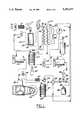
- FIG. 1is a schematic diagram of a refrigerant recovery system in accordance with one presently preferred embodiment of the invention
- FIG. 2is a fragmentary schematic diagram of a portion of the system illustrated in FIG. 1 showing a modified embodiment of the invention.
- FIG. 3is a fragmentary schematic diagram of a portion of the system illustrated in FIG. 1 showing a second modified embodiment of the invention.
- FIG. 1illustrates a refrigerant recovery system 10 in accordance with a presently preferred embodiment of the invention as comprising an input solenoid valve 12 coupled to a connector 14 for connection to equipment under service from which refrigerant is to be withdrawn.
- Refrigerant from valve 12is fed through a filter 16 and a check valve 18 to an accumulator 20 for separating liquid phase refrigerant from vapor phase refrigerant.
- a pressure sensor 17is connected between filter 16 and check valve 18.
- Accumulator 20comprises a canister 22 having an open internal volume. Refrigerant from check valve 18 is fed into the upper portion of the canister volume, and an outlet port from the upper portion of the canister volume is connected through a solenoid valve 24 to an oil separator 26.
- a refrigerant liquid level sensor 28 of any suitable typeis positioned within the lower portion of canister 22, and is operatively connected to solenoid valve 24. When liquid refrigerant is present at sensor 28, valve 24 is closed. On the other hand, when sensor 28 detects absence of liquid refrigerant within canister 22, valve 24 is opened.
- a liquid refrigerant port at the lower portion of canister 22is connected through a flow control valve 30 to the inlet of the evaporator section 32 of a combined evaporator/condenser unit 34.
- Control inputs to valve 30are connected to refrigerant bulbs 36, 38 positioned at the inlet and outlet sides of evaporator 32 respectively. Structure and function of control valve 30 and bulbs 36, 38 are disclosed in detail in co-pending application Ser. No. 07/641,433 assigned to the assignee hereof, to which reference may be made for more detailed discussion.
- the outlet of evaporator section 32is connected to the inlet of oil separator 26.
- valve 24when liquid phase input refrigerant is detected by sensor 28, valve 24 is closed, and the liquid refrigerant is preferentially fed through evaporator section 32 to oil separator 26.
- sensor 28opens valve 24, which thus bypasses evaporator 32 and feeds vapor phase refrigerant directly to oil separator 26.
- Refrigerantis fed from oil separator 26 through a filter/dryer unit 40 for removing water vapor, acid and other contaminants from refrigerant passing therethrough, to the inlet of a compressor 42 driven by a motor 44. Oil collected in separator 26 is selectively drained by a valve 46 to a catch bottle 48.
- the outlet of compressor 42is connected to a compressor oil separator 50, from which return oil is fed through a filter 52 and a solenoid valve 54 to the compressor inlet.
- the refrigerant outlet of separator 50is connected through a check valve 56 to a manual valve 58, which may be placed in the configuration as shown for normal recovery operation, or in an opposing configuration for clearing refrigerant from the system components.
- Valve 58is connected through a coil 60 that surrounds oil separator 50 in heat exchange relation with the separator wall and refrigerant within the separator.
- the general structure and function of separator 50 with coil 60are disclosed in U.S. Pat. No. 5,042,271, to which reference may be made for further details.
- the general structure and function of valve 58is disclosed in co-pending application Ser. No. 07/681,365 assigned to the assignee hereof, to which reference may be made for further details.
- the outlet end of coil 60is connected through the condenser section 62 of evaporator/condenser unit 34, and thence through a coil 64 that surrounds oil separator 26.
- the outlet end of coil 64is connected through a chamber 66 in heat exchange relationship with refrigerant captured within a bulb 68.
- the outlet side of chamber 66is connected through an air purge tank 70 to a liquid refrigerant filter/dryer 72 for removing any water, acid or particular contaminants that may remain within the refrigerant.
- the purge port of tank 70is connected to a manual valve 74, and to one input of a double-needle gage 76.
- the second input of gage 76is connected to bulb 68.
- Gage 76thus reads a pressure differential between air captured within operator may selectively purge air from within tank 70 by operation of valve 74.
- the structure and function of such air purge systemare disclosed in greater detail U.S. Pat. No. 5,005,369 and U.S. application Ser. No. 07/576,952 assigned to the assignee hereof, to which reference may be made for further detail.
- the outlet side of filter 72is connected through a moisture indicator 78, a check valve 80 and a manual valve 82 to a connector 84 for connection to the vapor port of a liquid refrigerant storage container 86.
- Valve 58is also connected to valve 82 through a check valve 88, and valve 58 is connected to the inlet of evaporator 32 in parallel with flow control valve 30 for selectively clearing refrigerant from coil 60, condenser 62 and coil 64 as described in above-noted U.S. application Ser. No. 07/681,365.
- connecter 14is coupled to refrigeration equipment from which refrigerant is to be recovered, and connector 84 is coupled to storage container 86 as shown.
- Compressor motor 44 and compressor 42are energized, and valve 12 is opened to initiate a refrigerant recovery operation. If incoming refrigerant to accumulator 20 is in liquid or mixed liquid/vapor phase, presence of liquid in the accumulator is detected by sensor 28 and valve 24 is closed. Such liquid refrigerant is fed through valve 30, evaporator 32, oil separator 26 and filter 40 to compressor 42, and thence from the compressor through oil separator 50, condenser 62, coil 64, air purge tank 70, filter 72, moisture indicator 78 and valve 82 to tank 86.
- sensor 28opens valve 24 as soon as all liquid phase refrigerant has been withdrawn from accumulator 20, so that incoming vapor phase refrigerant is fed directly to oil separator 26 and compressor 42 bypassing evaporator 32. In this way, not only is the rate of refrigerant recovery greatly enhanced, but superheating of input refrigerant already in vapor phase is avoided.
- pressure sensor 17functions to close valve 12 and/or remover energy from compressor motor 44.
- FIGS. 2 and 3illustrate modified embodiments of the invention, in which reference numerals identical to those employed in FIG. 1 indicate correspondingly identical parts.
- vapor/liquid separation accumulator 20 of FIG. 1is replaced by a sight glass 90 connected between filter 16 and control valve 30, through which an operator may observe the phase or phases of input refrigerant.
- Solenoid valve 24is connected between sight glass 90 and the inlet of oil separator 26, and is controlled by a manual switch 92 connected to a suitable source of electrical power (not shown).
- switch 92 and valve 24remain open, and all input refrigerant is fed to evaporator 32.
- switch 92is closed to energize valve 24 and thereby bypass refrigerant from evaporator 32.
- Unit 94comprises a closed generally cylindrical canister 96 having an open internal volume 98 and a condenser coil 100 disposed within the lower portion of volume 98.
- a pair of liquid ports and a pair of vapor portsare provided at the upper end of canister 94.
- heat-exchange/oil-separator unitis essentially the same as that disclosed in U.S. Pat. Nos. 4,768,347 and 4,809,520 noted above.
- the liquid ports of unit 94are connected to coil 60 of oil separator 50 and chamber 66 (FIG. 1) respectively.
- One vapor port of unit 94is connected to the inlet side of filter 40.
- a first liquid level sensor 102is positioned within canister 96 closely adjacent to but just above condenser coil 100 for sensing when refrigerant just covers the condenser coil.
- a second liquid refrigerant level sensor 104is positioned beneath sensor 102 for sensing a lower level of liquid refrigerant within canister 96.
- Sensor 102is operatively coupled to a first solenoid valve 106 for feeding refrigerant to the input port of canister 96.
- Sensor 104is operatively coupled to a second solenoid valve 108 connected in parallel with valve 106.
- Valve 106has a relatively restricted flow passage for selectively admitting liquid phase refrigerant, or mixed liquid/vapor phase refrigerant, to canister 96 under control of sensor 102. When sensor 102 detects that liquid refrigerant is below the level of the sensor, sensor 102 automatically opens valve 106 to admit additional liquid refrigerant to bring the refrigerant level backup to the position of the sensor, at which point valve 106 is
- valve 108is configured to have a relatively large refrigerant flow passage for admitting refrigerant in vapor phase under control of sensor 104. That is, when the level of refrigerant within volume 98 falls below the level of sensor 104, absence of input liquid phase refrigerant is inferred, and sensor 104 opens valve 108 for high-volume admission of refrigerant in vapor phase. Vapor phase refrigerant, either as admitted through valves 106, 108 or as evaporated from liquid phase refrigerant within the lower portion of canister 96, exits the canister through the second vapor port, and is fed to filter 40 and thence to compressor 42 (FIG. 1) as previously described. Thus, input refrigerant flow is controlled by sensors 102, 104 and valves 106, 108 as a function of refrigerant phase to maximize the refrigerant throughput without over flowing the heat exchange unit.
Landscapes
- Engineering & Computer Science (AREA)
- Physics & Mathematics (AREA)
- Mechanical Engineering (AREA)
- Thermal Sciences (AREA)
- General Engineering & Computer Science (AREA)
- Air-Conditioning For Vehicles (AREA)
Abstract
Description
Claims (26)
Priority Applications (1)
| Application Number | Priority Date | Filing Date | Title |
|---|---|---|---|
| US07/797,360US5203177A (en) | 1991-11-25 | 1991-11-25 | Refrigerant handling system with inlet refrigerant liquid/vapor flow control |
Applications Claiming Priority (1)
| Application Number | Priority Date | Filing Date | Title |
|---|---|---|---|
| US07/797,360US5203177A (en) | 1991-11-25 | 1991-11-25 | Refrigerant handling system with inlet refrigerant liquid/vapor flow control |
Publications (1)
| Publication Number | Publication Date |
|---|---|
| US5203177Atrue US5203177A (en) | 1993-04-20 |
Family
ID=25170619
Family Applications (1)
| Application Number | Title | Priority Date | Filing Date |
|---|---|---|---|
| US07/797,360Expired - LifetimeUS5203177A (en) | 1991-11-25 | 1991-11-25 | Refrigerant handling system with inlet refrigerant liquid/vapor flow control |
Country Status (1)
| Country | Link |
|---|---|
| US (1) | US5203177A (en) |
Cited By (28)
| Publication number | Priority date | Publication date | Assignee | Title |
|---|---|---|---|---|
| US5379607A (en)* | 1992-11-10 | 1995-01-10 | Polar Industries Ltd. | Refrigerant recovery and recycling system |
| US5400606A (en)* | 1994-03-14 | 1995-03-28 | Scuderi; Carmelo J. | Apparatus for recovering refrigerant |
| US5535595A (en)* | 1994-11-22 | 1996-07-16 | Spx Corporation | Refrigerant handling with centrifugal separation of non condensibles from refrigerant |
| US5540254A (en)* | 1994-09-01 | 1996-07-30 | Mcgowan; Willie J. | Apparatus for use in servicing and installing refrigeration systems without freon leakage |
| US5557940A (en)* | 1995-10-27 | 1996-09-24 | Hendricks; Roger G. | Portable heating unit for on-site charging of a cooling unit |
| US5560215A (en)* | 1992-05-14 | 1996-10-01 | Talarico; Angelo | Gas processor |
| US5634515A (en)* | 1995-12-28 | 1997-06-03 | Lambert; Kenneth W. | Geothermal heat-pump system and installation of same |
| US5678412A (en)* | 1996-07-23 | 1997-10-21 | Integral Sciences Incorporated | Method for changing lubricant types in refrigeration or air conditioning machinery using lubricant overcharge |
| US5685161A (en)* | 1996-01-25 | 1997-11-11 | National Refrigeration Products | Refrigerant recovery and recycling apparatus |
| WO1998013653A1 (en)* | 1996-09-27 | 1998-04-02 | Galbreath Charles E Sr | Refrigerant recycle and reclaim system |
| US5875638A (en)* | 1993-05-03 | 1999-03-02 | Copeland Corporation | Refrigerant recovery system |
| US5934091A (en)* | 1997-10-31 | 1999-08-10 | Century Manufacturing Company | Refrigerant recovery and recycling system |
| US6138462A (en)* | 1999-03-19 | 2000-10-31 | Spx Corporation | Refrigerant recovery and recharging system with automatic oil drain |
| US6244055B1 (en) | 1999-06-01 | 2001-06-12 | Century Manufacturing Company | Refrigerant recovery and recycling system |
| WO2001046629A1 (en)* | 1999-12-23 | 2001-06-28 | James Ross | Hot discharge gas desuperheater |
| US6263691B1 (en)* | 1997-09-12 | 2001-07-24 | Daikin Industries, Ltd. | Refrigerant recovering apparatus and refrigerant recovering method |
| US6321542B1 (en)* | 1997-04-02 | 2001-11-27 | Daikin Industries, Ltd. | Method for cleaning pipe and pipe cleaning apparatus for refrigerating apparatus |
| US6408637B1 (en) | 1999-11-01 | 2002-06-25 | Century Mfg. Co. | Apparatus and method for recovering and recycling refrigerant |
| US20080127667A1 (en)* | 2006-11-30 | 2008-06-05 | Lennox Manufacturing Inc. | System pressure actuated charge compensator |
| US20100010681A1 (en)* | 2002-12-09 | 2010-01-14 | Hudson Technologies, Inc. | Method and apparatus for optimizing refrigeration systems |
| US20110088420A1 (en)* | 2010-12-29 | 2011-04-21 | Michael Shelton | Chemical State Monitor for Refrigeration System |
| US20110094247A1 (en)* | 2006-12-19 | 2011-04-28 | Spx Corporation | A/C Maintenance System Using Heat Transfer from the Condenser to the Oil Separator for Improved Efficiency |
| US20120006817A1 (en)* | 2010-07-07 | 2012-01-12 | Krones Ag | Device for tempering |
| US20120041608A1 (en)* | 2002-12-09 | 2012-02-16 | Hudson Technologies, Inc. | Method and apparatus for optimizing refrigeration systems |
| US20130283830A1 (en)* | 2012-04-30 | 2013-10-31 | Trane International Inc. | Refrigeration system with purge and acid filter |
| US10041713B1 (en) | 1999-08-20 | 2018-08-07 | Hudson Technologies, Inc. | Method and apparatus for measuring and improving efficiency in refrigeration systems |
| US20190178543A1 (en)* | 2017-12-12 | 2019-06-13 | Rheem Manufacturing Company | Accumulator and Oil Separator |
| US20230296300A1 (en)* | 2022-03-17 | 2023-09-21 | Carrier Corporation | Refrigerant recovery device and method of operation |
Citations (9)
| Publication number | Priority date | Publication date | Assignee | Title |
|---|---|---|---|---|
| US2270934A (en)* | 1939-10-13 | 1942-01-27 | Jr Edward F Dickieson | Control for refrigerating devices |
| US3955374A (en)* | 1974-10-23 | 1976-05-11 | Zearfoss Jr Elmer W | Refrigeration apparatus and method |
| US4261178A (en)* | 1979-01-19 | 1981-04-14 | Robinair Manufacturing Corporation | Environmental protection refrigeration disposal and charging system |
| US4646527A (en)* | 1985-10-22 | 1987-03-03 | Taylor Shelton E | Refrigerant recovery and purification system |
| US4768347A (en)* | 1987-11-04 | 1988-09-06 | Kent-Moore Corporation | Refrigerant recovery and purification system |
| US4856289A (en)* | 1988-07-08 | 1989-08-15 | Lofland Spencer G | Apparatus for reclaiming and purifying chlorinated fluorocarbons |
| US4981020A (en)* | 1990-02-02 | 1991-01-01 | Scuderi Carmelo J | Apparatus for recovering refrigerant |
| US5005369A (en)* | 1989-09-11 | 1991-04-09 | Kent-Moore Corporation | Refrigerant purification with automatic air purge |
| US5042271A (en)* | 1990-01-22 | 1991-08-27 | Kent-Moore Corporation | Refrigerant handling system with compressor oil separation |
- 1991
- 1991-11-25USUS07/797,360patent/US5203177A/ennot_activeExpired - Lifetime
Patent Citations (10)
| Publication number | Priority date | Publication date | Assignee | Title |
|---|---|---|---|---|
| US2270934A (en)* | 1939-10-13 | 1942-01-27 | Jr Edward F Dickieson | Control for refrigerating devices |
| US3955374A (en)* | 1974-10-23 | 1976-05-11 | Zearfoss Jr Elmer W | Refrigeration apparatus and method |
| US4261178A (en)* | 1979-01-19 | 1981-04-14 | Robinair Manufacturing Corporation | Environmental protection refrigeration disposal and charging system |
| US4646527A (en)* | 1985-10-22 | 1987-03-03 | Taylor Shelton E | Refrigerant recovery and purification system |
| US4768347A (en)* | 1987-11-04 | 1988-09-06 | Kent-Moore Corporation | Refrigerant recovery and purification system |
| US4809520A (en)* | 1987-11-04 | 1989-03-07 | Kent-Moore Corporation | Refrigerant recovery and purification system |
| US4856289A (en)* | 1988-07-08 | 1989-08-15 | Lofland Spencer G | Apparatus for reclaiming and purifying chlorinated fluorocarbons |
| US5005369A (en)* | 1989-09-11 | 1991-04-09 | Kent-Moore Corporation | Refrigerant purification with automatic air purge |
| US5042271A (en)* | 1990-01-22 | 1991-08-27 | Kent-Moore Corporation | Refrigerant handling system with compressor oil separation |
| US4981020A (en)* | 1990-02-02 | 1991-01-01 | Scuderi Carmelo J | Apparatus for recovering refrigerant |
Cited By (44)
| Publication number | Priority date | Publication date | Assignee | Title |
|---|---|---|---|---|
| US5560215A (en)* | 1992-05-14 | 1996-10-01 | Talarico; Angelo | Gas processor |
| US5379607A (en)* | 1992-11-10 | 1995-01-10 | Polar Industries Ltd. | Refrigerant recovery and recycling system |
| US5875638A (en)* | 1993-05-03 | 1999-03-02 | Copeland Corporation | Refrigerant recovery system |
| US5400606A (en)* | 1994-03-14 | 1995-03-28 | Scuderi; Carmelo J. | Apparatus for recovering refrigerant |
| US5540254A (en)* | 1994-09-01 | 1996-07-30 | Mcgowan; Willie J. | Apparatus for use in servicing and installing refrigeration systems without freon leakage |
| US5535595A (en)* | 1994-11-22 | 1996-07-16 | Spx Corporation | Refrigerant handling with centrifugal separation of non condensibles from refrigerant |
| US5557940A (en)* | 1995-10-27 | 1996-09-24 | Hendricks; Roger G. | Portable heating unit for on-site charging of a cooling unit |
| US5634515A (en)* | 1995-12-28 | 1997-06-03 | Lambert; Kenneth W. | Geothermal heat-pump system and installation of same |
| US5685161A (en)* | 1996-01-25 | 1997-11-11 | National Refrigeration Products | Refrigerant recovery and recycling apparatus |
| US5678412A (en)* | 1996-07-23 | 1997-10-21 | Integral Sciences Incorporated | Method for changing lubricant types in refrigeration or air conditioning machinery using lubricant overcharge |
| WO1998013653A1 (en)* | 1996-09-27 | 1998-04-02 | Galbreath Charles E Sr | Refrigerant recycle and reclaim system |
| US6029472A (en)* | 1996-09-27 | 2000-02-29 | Galbreath, Sr.; Charles E. | Refrigerant recycle and reclaim system |
| US6321542B1 (en)* | 1997-04-02 | 2001-11-27 | Daikin Industries, Ltd. | Method for cleaning pipe and pipe cleaning apparatus for refrigerating apparatus |
| US6263691B1 (en)* | 1997-09-12 | 2001-07-24 | Daikin Industries, Ltd. | Refrigerant recovering apparatus and refrigerant recovering method |
| US5934091A (en)* | 1997-10-31 | 1999-08-10 | Century Manufacturing Company | Refrigerant recovery and recycling system |
| US6138462A (en)* | 1999-03-19 | 2000-10-31 | Spx Corporation | Refrigerant recovery and recharging system with automatic oil drain |
| US6244055B1 (en) | 1999-06-01 | 2001-06-12 | Century Manufacturing Company | Refrigerant recovery and recycling system |
| US10041713B1 (en) | 1999-08-20 | 2018-08-07 | Hudson Technologies, Inc. | Method and apparatus for measuring and improving efficiency in refrigeration systems |
| US6408637B1 (en) | 1999-11-01 | 2002-06-25 | Century Mfg. Co. | Apparatus and method for recovering and recycling refrigerant |
| WO2001046629A1 (en)* | 1999-12-23 | 2001-06-28 | James Ross | Hot discharge gas desuperheater |
| US9423165B2 (en)* | 2002-12-09 | 2016-08-23 | Hudson Technologies, Inc. | Method and apparatus for optimizing refrigeration systems |
| US10436488B2 (en) | 2002-12-09 | 2019-10-08 | Hudson Technologies Inc. | Method and apparatus for optimizing refrigeration systems |
| US8046107B2 (en)* | 2002-12-09 | 2011-10-25 | Hudson Technologies, Inc. | Method and apparatus for optimizing refrigeration systems |
| US20120041608A1 (en)* | 2002-12-09 | 2012-02-16 | Hudson Technologies, Inc. | Method and apparatus for optimizing refrigeration systems |
| US20100010681A1 (en)* | 2002-12-09 | 2010-01-14 | Hudson Technologies, Inc. | Method and apparatus for optimizing refrigeration systems |
| US8463441B2 (en)* | 2002-12-09 | 2013-06-11 | Hudson Technologies, Inc. | Method and apparatus for optimizing refrigeration systems |
| US20130269376A1 (en)* | 2002-12-09 | 2013-10-17 | Hudson Technologies, Inc. | Method and apparatus for optimizing refrigeration systems |
| US9163866B2 (en) | 2006-11-30 | 2015-10-20 | Lennox Industries Inc. | System pressure actuated charge compensator |
| US20080127667A1 (en)* | 2006-11-30 | 2008-06-05 | Lennox Manufacturing Inc. | System pressure actuated charge compensator |
| US8429921B2 (en)* | 2006-12-19 | 2013-04-30 | Service Solutions U.S. Llc | A/C maintenance system using heat transfer from the condenser to the oil separator for improved efficiency |
| US20110094247A1 (en)* | 2006-12-19 | 2011-04-28 | Spx Corporation | A/C Maintenance System Using Heat Transfer from the Condenser to the Oil Separator for Improved Efficiency |
| US20120006817A1 (en)* | 2010-07-07 | 2012-01-12 | Krones Ag | Device for tempering |
| US9146048B2 (en) | 2010-12-29 | 2015-09-29 | Michael Shelton | Chemical state monitor for refrigeration system |
| US20110088420A1 (en)* | 2010-12-29 | 2011-04-21 | Michael Shelton | Chemical State Monitor for Refrigeration System |
| EP3760950A1 (en)* | 2012-04-30 | 2021-01-06 | Trane International Inc. | Refrigeration system with purge and acid filter |
| US10190808B2 (en)* | 2012-04-30 | 2019-01-29 | Trane International Inc. | Refrigeration system with purge and acid filter |
| EP2861920A4 (en)* | 2012-04-30 | 2016-03-02 | Trane Int Inc | REFRIGERATION SYSTEM COMPRISING A PURGE AND AN ACID FILTER |
| US20130283830A1 (en)* | 2012-04-30 | 2013-10-31 | Trane International Inc. | Refrigeration system with purge and acid filter |
| US11073315B2 (en) | 2012-04-30 | 2021-07-27 | Trane International Inc. | Refrigeration system with purge and acid filter |
| US11635239B2 (en) | 2012-04-30 | 2023-04-25 | Trane International Inc. | Refrigeration system with purge and acid filter |
| EP4445987A3 (en)* | 2012-04-30 | 2025-01-15 | Trane International Inc. | Refrigeration system with purge and acid filter |
| US20190178543A1 (en)* | 2017-12-12 | 2019-06-13 | Rheem Manufacturing Company | Accumulator and Oil Separator |
| US10845106B2 (en)* | 2017-12-12 | 2020-11-24 | Rheem Manufacturing Company | Accumulator and oil separator |
| US20230296300A1 (en)* | 2022-03-17 | 2023-09-21 | Carrier Corporation | Refrigerant recovery device and method of operation |
Similar Documents
| Publication | Publication Date | Title |
|---|---|---|
| US5203177A (en) | Refrigerant handling system with inlet refrigerant liquid/vapor flow control | |
| US4939905A (en) | Recovery system for differing refrigerants | |
| US5193351A (en) | Refrigerant recovery and purification system | |
| US4805416A (en) | Refrigerant recovery, purification and recharging system | |
| US5024061A (en) | Recovery processing and storage unit | |
| US6016661A (en) | Refrigerant recovery system | |
| US4862699A (en) | Method and apparatus for recovering, purifying and separating refrigerant from its lubricant | |
| US5090211A (en) | Refrigerant recovery and recycling system | |
| US5875638A (en) | Refrigerant recovery system | |
| US5172562A (en) | Refrigerant recovery, purification and recharging system and method | |
| US4768347A (en) | Refrigerant recovery and purification system | |
| US6029472A (en) | Refrigerant recycle and reclaim system | |
| US5182918A (en) | Refrigerant recovery system | |
| US4938031A (en) | Refrigerant recovery and purification system | |
| US5095713A (en) | Refrigerant handling system and method with multiple refrigerant capability | |
| US5209077A (en) | Refrigerant recovery system | |
| US6244055B1 (en) | Refrigerant recovery and recycling system | |
| US6408637B1 (en) | Apparatus and method for recovering and recycling refrigerant | |
| US5325675A (en) | Refrigerant handling system and method with enhanced recovery vacuum capability | |
| US5261249A (en) | Refrigerant handling system with auxiliary condenser flow control | |
| US5367886A (en) | Refrigerant handling system with air purge and system clearing capabilities | |
| US5761924A (en) | Refrigerant recycling apparatus and method | |
| US5934091A (en) | Refrigerant recovery and recycling system | |
| US5361594A (en) | Refrigeration recovery and purification | |
| JPS6030686Y2 (en) | Purge device for refrigeration equipment |
Legal Events
| Date | Code | Title | Description |
|---|---|---|---|
| AS | Assignment | Owner name:SPX CORPORATION, A CORP. OF DE, MICHIGAN Free format text:ASSIGNMENT OF ASSIGNORS INTEREST.;ASSIGNORS:MANZ, KENNETH W.;POWERS, CHRISTOPHER M.;LAUKHUF, GREGG E.;REEL/FRAME:005929/0474 Effective date:19911101 | |
| FPAY | Fee payment | Year of fee payment:4 | |
| AS | Assignment | Owner name:CHASE MANHATTAN BANK, THE, NEW YORK Free format text:CONDITIONAL ASSIGNMENT OF AND SECURITY INTEREST IN PATENT RIGHTS;ASSIGNOR:SPX DEVELOPMENT CORPORATION;REEL/FRAME:011007/0116 Effective date:20000613 | |
| AS | Assignment | Owner name:SPX DEVELOPMENT CORPORATION, MICHIGAN Free format text:ASSIGNMENT OF ASSIGNORS INTEREST;ASSIGNOR:SPX CORPORATION (DE CORP.);REEL/FRAME:011103/0887 Effective date:20000101 | |
| REMI | Maintenance fee reminder mailed | ||
| FEPP | Fee payment procedure | Free format text:PETITION RELATED TO MAINTENANCE FEES DENIED/DISMISSED (ORIGINAL EVENT CODE: PMFD); ENTITY STATUS OF PATENT OWNER: LARGE ENTITY Free format text:PETITION RELATED TO MAINTENANCE FEES FILED (ORIGINAL EVENT CODE: PMFP); ENTITY STATUS OF PATENT OWNER: LARGE ENTITY | |
| FEPP | Fee payment procedure | Free format text:PETITION RELATED TO MAINTENANCE FEES GRANTED (ORIGINAL EVENT CODE: PMFG); ENTITY STATUS OF PATENT OWNER: LARGE ENTITY | |
| SULP | Surcharge for late payment | ||
| FPAY | Fee payment | Year of fee payment:8 | |
| SULP | Surcharge for late payment | ||
| STCF | Information on status: patent grant | Free format text:PATENTED CASE | |
| FP | Lapsed due to failure to pay maintenance fee | Effective date:20010420 | |
| PRDP | Patent reinstated due to the acceptance of a late maintenance fee | Effective date:20010615 | |
| REMI | Maintenance fee reminder mailed | ||
| FPAY | Fee payment | Year of fee payment:12 | |
| SULP | Surcharge for late payment | Year of fee payment:11 | |
| AS | Assignment | Owner name:GSLE SUBCO L.L.C., NORTH CAROLINA Free format text:MERGER;ASSIGNOR:SPX DEVELOPMENT CORPORATION;REEL/FRAME:016182/0067 Effective date:20041231 | |
| AS | Assignment | Owner name:GSLE SUBCO LLC (FORMERLY KNOWN AS SPX DEVELOPMENT Free format text:TERMINATION AND RELEASE OF SECURITY INTEREST IN PATENT RIGHTS (PREVIOUSLY RECORDED AT REEL 11007 FRAME 0116);ASSIGNOR:JPMORGAN CHASE BANK, N.A., AS COLLATERAL AGENT;REEL/FRAME:016851/0745 Effective date:20051118 |