US5203089A - Railroad vehicle for measuring the geometrical parameters of railroad track - Google Patents
Railroad vehicle for measuring the geometrical parameters of railroad trackDownload PDFInfo
- Publication number
- US5203089A US5203089AUS07/712,273US71227391AUS5203089AUS 5203089 AUS5203089 AUS 5203089AUS 71227391 AUS71227391 AUS 71227391AUS 5203089 AUS5203089 AUS 5203089A
- Authority
- US
- United States
- Prior art keywords
- track
- axle
- rail
- bogie
- vehicle
- Prior art date
- Legal status (The legal status is an assumption and is not a legal conclusion. Google has not performed a legal analysis and makes no representation as to the accuracy of the status listed.)
- Expired - Lifetime
Links
- 238000005259measurementMethods0.000claimsabstractdescription27
- 230000003287optical effectEffects0.000claimsabstractdescription10
- 238000006073displacement reactionMethods0.000abstract1
- 238000010586diagramMethods0.000description7
- 230000001133accelerationEffects0.000description5
- 230000005484gravityEffects0.000description3
- 230000035939shockEffects0.000description2
- 238000009825accumulationMethods0.000description1
- 239000000428dustSubstances0.000description1
- 239000004519greaseSubstances0.000description1
- 239000011159matrix materialSubstances0.000description1
Images


Classifications
- G—PHYSICS
- G01—MEASURING; TESTING
- G01B—MEASURING LENGTH, THICKNESS OR SIMILAR LINEAR DIMENSIONS; MEASURING ANGLES; MEASURING AREAS; MEASURING IRREGULARITIES OF SURFACES OR CONTOURS
- G01B11/00—Measuring arrangements characterised by the use of optical techniques
- G01B11/14—Measuring arrangements characterised by the use of optical techniques for measuring distance or clearance between spaced objects or spaced apertures
- B—PERFORMING OPERATIONS; TRANSPORTING
- B61—RAILWAYS
- B61K—AUXILIARY EQUIPMENT SPECIALLY ADAPTED FOR RAILWAYS, NOT OTHERWISE PROVIDED FOR
- B61K9/00—Railway vehicle profile gauges; Detecting or indicating overheating of components; Apparatus on locomotives or cars to indicate bad track sections; General design of track recording vehicles
- B61K9/08—Measuring installations for surveying permanent way
Definitions
- the present inventionrelates to a railroad vehicle for measuring the geometrical parameters of railroad track, and in particular the following parameters:
- gauge of the rails of the tracki.e. the distance which separates the inside faces of the rails in a cross section of the track
- deflection or liningi.e. the distance in a horizontal plane between a chord of a given length (e.g. 10 meters) and a point on the rail situated at a given distance from one of the ends of the chord (e.g. 4.5 meters from one end and 5.5 meters from the other end). This measurement is performed for each rail;
- canti.e. the distance in a cross section between one of the rails and a horizontal based on the other rail;
- the length of the rectanglemay, for example, be about that of a bogie: this is “short base” warping.
- the length of the rectanglemay be about the distance between the two bogies of a vehicle; this is "long base” warping:
- Such measurementsare currently performed by means of a vehicle equipped with mechanical members making contact with the rails of the track.
- the accumulation of patches of grease on the trackinterferes with these measurements, such that it is preferable to perform these measurements without using mechanical members in contact with the track.
- the present inventionprovides a railroad vehicle for measuring by optical means the geometrical parameters of a track comprising a first rail and a second rail, the vehicle moving on said track and including a first bogie and a second bogie each of which has two main axles, said vehicle being characterized in that each of the first and second bogies includes a third axle with independent wheels, the vehicle also including:
- a third bogiecomprising two main axles, capable of moving relative to each other about an axis passing through their centers, and a third axle with independent wheels, placed between the two said axles;
- each proximity meterincluding an emitter and a receiver placed so as to look at the inside faces of the first rail and the second rail respectively;
- first and second pairs of optical distance gaugeswhose receivers are disposed head-to-tail in pairs at the ends of the central axle of the third bogie and whose emitters are disposed at the ends of the independent-wheel axles respectively of the first and second bogies;
- a third pair of distance gaugeswhose receivers are placed at the ends of one of the main axles of the third bogie and whose emitters are disposed at the ends of the other axle of the third bogie.
- the ray emitted by the proximity meter secured to an independent-wheel axle for measuring the gauge of the trackis reflected towards the rail by a mirror secured to said axle.
- the ray emitted by the proximity meter secured to an independent-wheel axle for measuring the gauge of the trackis reflected towards the rail by at least one mirror secured to the wheel of said axle.
- the ray reflected on the mirrorreaches the rail through a hole made in the flange of the wheel.
- FIG. 1is an elevation view of a vehicle of the invention
- FIG. 2is a view from below of the same vehicle
- FIG. 3is a diagram illustrating the measurement of track gauge
- FIG. 4is a diagrammatic view illustrating how a proximity meter is used to measure gauge, in a first embodiment
- FIG. 5is a diagrammatic view illustrating how a proximity meter is used to measure gauge, in a second embodiment
- FIG. 6is a diagram of the device of the invention for measuring leveling and lining
- FIG. 7is a diagram of the device of the invention for measuring warping
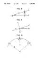
- FIG. 8is a diagram showing how a cant parameter is defined
- FIG. 9is a diagram of the accelerations on the pendulum weight of a tilt indicator which is used to measure the cant parameter.
- FIG. 10is a diagram explaining how the radius of curvature of the track is measured.
- reference 1designates a railroad vehicle of the invention, running on two rails 2 and 3 of a railroad track.
- the vehicleis provided with a first end bogie 10 and a second end bogie 20, each conventionally embodied by means of two one-piece axles with conical wheels referenced 11 and 12, and 21 and 22 respectively.
- the vehicleincludes a third bogie 30, disposed between the bogies 10 and 20, and having special features which are described below.
- each of the bogies 10 and 20has a third axle, referenced respectively 13 and 23 and provided with independent wheels 14 and 15 and 24 and 25 that are preferably smaller in diameter than the other wheels of the bogies.
- These additional axles, placed between the main axles,are preferably retractable so that they leave the track when the vehicle is not performing measurements.
- the third bogie 30includes two axles 31 and 32 capable of pivoting about a line passing through their respective centers; they are linked to a common crossbeam by suitable joints 33A and 33B.
- the wheels of axle 31are referenced 34 and 35, and the wheels of axle 32 are referenced 36 and 37.
- the bogie 30has a third axle 39, disposed between the axles 31 and 32 and linked at 40 to the crossbeam 33; the axle 39 is provided with two independent wheels 41 and 42.
- the axle 39is preferably retractable.
- independent-wheel axle and “additional” axleare used below interchangeably to designate the axles 13, 23, and 39.
- This measurementcan be made by equipping only one of the independent-wheel axles in the manner described below. In practice, all three additional axles 13, 23 and 39 are equipped so that lining can also be measured, as shown below.
- FIG. 3in which only the rails 2 and 3 and the additional axles 13, 23 and 39 are shown.
- Each axleis provided with a pair of proximity meters; the term "proximity meter” designates an optical device comprising a light-emitting source (also called an emitter) and a receiving member which includes receiver diodes, for example. The emitted ray is directed onto an object and reflects off it; the apparatus provides a measurement of the distance separating the object from the apparatus.
- proximity metersare commercially available for example from Reom, under the trademark Capitolas.
- the figureshows that the additional axle 13 is provided with a proximity meter 52, disposed at the same end of the axle as the rail 2, and with there being a proximity meter 53 disposed at the same end of the axle as the rail 3.
- the beam from proximity meter 52is directed onto the inside face of rail 2 and reflects off it; likewise, the beam from proximity meter 53 is directed onto the inside face of rail 3. If the distance separating the proximity meter 52 from the rail 2 and measured by the proximity meter 52 is designated e, the distance separating the proximity meter 53 from the rail 3 and measured by the proximity meter 53 is designated e', and the distance separating the proximity meters 52 and 53 is designated a, then the width of the track is equal to: a+e+e'.
- the proximity meters with which the additional axle 23 is equippedare referenced 62 and 63, and the proximity meters with which the additional axle 39 is equipped are referenced 72 and 73.
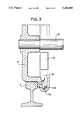
- FIG. 4illustrates a first embodiment in which the proximity meter 52 secured to the crossbeam of axle 13 is also secured to a mirror 54; this mirror reflects the light beam 55 emitted by the proximity meter towards the rail 2; the ray reaches the inside face of the rail 2 after passing through a hole 56 made in the flange 15A of the wheel 15. The reflected beam follows the same path in the opposite direction. One measurement can thus be made per rotation of the wheel. If a plurality of equidistant holes are disposed around the periphery of the wheel rim, a plurality of measurements can be made per rotation of the wheel. Since the mirror is disposed inside the flange it can be protected against pollution such as mud, moisture, and dust, and against mechanical shocks.
- the proximity meter 52 secured to the crossbeam of axle 13is linked to at least one mirror 54A which is secured to the wheel 15; the beam 55 reaches the inside face of rail 2 after passing through a hole 56 made in the flange 15A of the wheel 15; the reflected ray follows the same path in the opposite direction.
- one mirrorone measurement can be made per rotation of the wheel; it is possible to dispose a plurality of mirrors and an equal number of holes in order to obtain a plurality of measurements per rotation of the wheel.
- a distance gaugeis an optical device comprising a light-emitting source and a receiver consisting in particular of a matrix of receiver diodes. Such an apparatus provides the distance between the relative horizontal and vertical positions of the receiver and the emitter from a reference point.
- a distance gaugeis commercially available for example from Micromaine under the trademark Sirrah.
- the receivers of the distance gaugesare placed on the additional axle 39 of the bogie 30 and the emitters of the distance gauges are placed on the additional axles 13 and 23 of bogies 10 and 20. More precisely, for measuring the parameters of rail 2, a pair of distance gauges are used, their component parts being situated at the ends of the axles next the rail in question. Only the apparatus relative to measuring the parameters of rail 2 are described below, the apparatus for measuring the parameters of rail 3, referenced in FIG. 6 with the index A, being identical and situated at the other ends of the axles.
- two distance gaugesare used, their receivers 81 and 82 being placed head-to-tail at the end of the crossbeam 39 next to the rail 2; these receive the beams emitted by the emitters 91 and 92, placed on the crossbeams 13 and 23 respectively, at those ends of the crossbeams that are next to the rail 2. These components are adjusted such that the horizontal and vertical distances measured on a perfectly horizontal and rectilinear track have a reference value.
- the horizontal and vertical distances measured by the receivers 81 and 82, together with the measurements made by the proximity meters 52, 72 and 62 (FIG. 3),provide a measurement of the leveling and lining of the rail 2.
- the receivers 93 and 93A of two distance gaugesare situated at the ends of the crossbeam of axle 31; the associated emitters 94 and 94A are placed at the ends of axle 36.
- the adjustmentis such that perfectly plane and rectilinear track has a deflection of zero.
- the horizontal and vertical distances measured by the receivers 93 and 93Aprovide a measurement of track warping.
- the value of a'is obtained by means of a tilt indicator on board the vehicle and preferably disposed on the third bogie.
- This tilt indicatoris represented in FIG. 6 by a rectangle 200.
- a tilt indicatordetects an angle relative to gravity: a pendulum weight is supported by a moving frame suspended from a flexible blade. If the apparatus is on a horizontal plane, the pendulum weight support is vertical; if the apparatus is sloping, the pendulum weight tends to move under the force of gravity. This movement is detected by an electrical proximity sensor and a servo-control circuit transforms this movement into a proportional current which is applied to the moving frame in order to return the pendulum weight to its position. A signal kv, proportional to the voltage across the terminals of the frame, provides the measurement of the angle a'.
- Such tilt indicatorsare well known, for example as commercially available from Schaevitz.
- the pendulum weight of the tilt indicatoris subjected not only to the acceleration g due to gravity, but also to a centrifugal acceleration proportional to V 2 /R, where V designates the speed of the vehicle and R designates the radius of the curvature of the track.
- the speed V of the vehicleis measured by conventional means.
- the radius of curvature Ris determined in the manner shown below.
- FIG. 9is a diagram of the acceleration to which the pendulum weight of the tilt indicator is subjected.
- the radius of the curvatureis measured by calculation, by means of the apparatus which allows the parameter of track lining to be measured.
- the measurementis made simultaneously on both rails of the track and the mean of the two measurements is taken.
- FIG. 10illustrates the theory of this measurement, but for the sake of clarity only one of the two rails is shown.
- the distance gauges 81 and 91 and 82 and 92are used.
- the radius of the curvature Ris given by the solution of the system:
- xC and yCdesignate the coordinates of the center C of the circle passing through the points A, B and D.
- the inventionwhich is based on the use of a additional bogie and additional axles having independent wheels, and also on measuring members placed directly on the axles, allows measurement results to be obtained without interference from any movement or deformation of the body of the vehicle.
- the body of vehicle 1 of the vehicle, FIG. 2presents a central portion 100, delimited by two narrower portions 101 and 102; the portion 100 has side windows 104 and 105 and oblique windows 106 and 107 and 108 and 109; the operator rides in the central portion and can thus observe signs outside the track (e.g. milestones).
- the vehicleis symmetrical, which allows it to be used in both travel directions.
Landscapes
- Engineering & Computer Science (AREA)
- Mechanical Engineering (AREA)
- Physics & Mathematics (AREA)
- General Physics & Mathematics (AREA)
- Length Measuring Devices With Unspecified Measuring Means (AREA)
- Length Measuring Devices By Optical Means (AREA)
- Machines For Laying And Maintaining Railways (AREA)
Abstract
Description
d=E·sin a' (FIG. 8)
(V.sup.2 /R) cos a'-g sin a'=kv
(xA-xC).sup.2 +(yA-yC).sup.2 =R.sup.2
(xD-xC).sup.2 +(yD-yC).sup.2 =R.sup.2
xC.sup.2 +yC.sup.2 =R.sup.2
Claims (6)
Applications Claiming Priority (2)
| Application Number | Priority Date | Filing Date | Title |
|---|---|---|---|
| FR9007276AFR2662984B1 (en) | 1990-06-12 | 1990-06-12 | VEHICLE ON TRACKS FOR MEASUREMENT OF GEOMETRIC TRACK PARAMETERS. |
| FR9007276 | 1990-06-12 |
Publications (1)
| Publication Number | Publication Date |
|---|---|
| US5203089Atrue US5203089A (en) | 1993-04-20 |
Family
ID=9397501
Family Applications (1)
| Application Number | Title | Priority Date | Filing Date |
|---|---|---|---|
| US07/712,273Expired - LifetimeUS5203089A (en) | 1990-06-12 | 1991-06-10 | Railroad vehicle for measuring the geometrical parameters of railroad track |
Country Status (7)
| Country | Link |
|---|---|
| US (1) | US5203089A (en) |
| EP (1) | EP0461628B1 (en) |
| AT (1) | ATE104620T1 (en) |
| DE (1) | DE69101742T2 (en) |
| DK (1) | DK0461628T3 (en) |
| ES (1) | ES2054398T3 (en) |
| FR (1) | FR2662984B1 (en) |
Cited By (43)
| Publication number | Priority date | Publication date | Assignee | Title |
|---|---|---|---|---|
| WO1996000159A1 (en)* | 1994-06-23 | 1996-01-04 | Groenskov Leif | Arrangement for measuring the quality of rails, in which a movable frame is connected to the bogie |
| US5720110A (en)* | 1994-10-29 | 1998-02-24 | Abb Patent Gmbh | Configuration for detecting gaps in a conductor rail for electric rail vehicles being fed through conductor rails |
| US6158352A (en)* | 1997-10-06 | 2000-12-12 | Franz Plasser Bahnbaumaschinen-Industriegesellschaft M.B.H. | Machine and method for rehabilitating a track |
| US6415522B1 (en)* | 1999-09-09 | 2002-07-09 | Matisa Material Industriel S.A. | Vehicle for measuring the geometric condition of a railway track |
| US6725782B1 (en)* | 2003-03-24 | 2004-04-27 | Franz Plasser Bahnbaumaschinen-Industriegesellschaft M.B.H | Railroad test vehicle comprising a railroad measurement axle suspension |
| US6804621B1 (en)* | 2003-04-10 | 2004-10-12 | Tata Consultancy Services (Division Of Tata Sons, Ltd) | Methods for aligning measured data taken from specific rail track sections of a railroad with the correct geographic location of the sections |
| US20040244637A1 (en)* | 2003-01-27 | 2004-12-09 | Ensco, Inc. | Mount apparatus for mounting a measurement device on a rail car |
| US20070213926A1 (en)* | 2004-04-21 | 2007-09-13 | J. Muller Ag | Method For Measuring Tracks |
| US7463348B2 (en) | 2006-07-10 | 2008-12-09 | General Electric Company | Rail vehicle mounted rail measurement system |
| US20090094848A1 (en)* | 2006-01-31 | 2009-04-16 | Deltarail Group Limited | Track Twist Monitoring |
| US20100078527A1 (en)* | 2007-05-22 | 2010-04-01 | Knorr-Bremse Systeme For Schienenfahrzeuge Gmbh | Device and method for error monitoring for undercarriage components of rail vehicles |
| US20100154233A1 (en)* | 2007-07-31 | 2010-06-24 | Josef Theurer | Method of measuring a track position |
| US20110216200A1 (en)* | 2002-06-04 | 2011-09-08 | Wing Yeung Chung | Locomotive wireless video recorder and recording system |
| US8914171B2 (en) | 2012-11-21 | 2014-12-16 | General Electric Company | Route examining system and method |
| US20150377653A1 (en)* | 2014-06-27 | 2015-12-31 | System 7 - Railsupport GmbH | Device for surveying tracks |
| US9255913B2 (en) | 2013-07-31 | 2016-02-09 | General Electric Company | System and method for acoustically identifying damaged sections of a route |
| US9481385B2 (en) | 2014-01-09 | 2016-11-01 | General Electric Company | Systems and methods for predictive maintenance of crossings |
| US9671358B2 (en) | 2012-08-10 | 2017-06-06 | General Electric Company | Route examining system and method |
| US9702715B2 (en) | 2012-10-17 | 2017-07-11 | General Electric Company | Distributed energy management system and method for a vehicle system |
| US9733625B2 (en) | 2006-03-20 | 2017-08-15 | General Electric Company | Trip optimization system and method for a train |
| US9810533B2 (en) | 2011-04-27 | 2017-11-07 | Trimble Inc. | Railway track monitoring |
| US9828010B2 (en) | 2006-03-20 | 2017-11-28 | General Electric Company | System, method and computer software code for determining a mission plan for a powered system using signal aspect information |
| US9875414B2 (en) | 2014-04-15 | 2018-01-23 | General Electric Company | Route damage prediction system and method |
| US9873441B1 (en) | 2016-08-04 | 2018-01-23 | Ensco, Inc. | Rail vehicle based deployable gage restraint measurement system |
| US9873442B2 (en) | 2002-06-04 | 2018-01-23 | General Electric Company | Aerial camera system and method for identifying route-related hazards |
| US9950722B2 (en) | 2003-01-06 | 2018-04-24 | General Electric Company | System and method for vehicle control |
| US9956974B2 (en) | 2004-07-23 | 2018-05-01 | General Electric Company | Vehicle consist configuration control |
| AT519263B1 (en)* | 2016-12-19 | 2018-05-15 | Plasser & Theurer Export Von Bahnbaumaschinen Gmbh | Track measuring vehicle and method for detecting a track geometry of a track |
| US10006877B2 (en) | 2014-08-20 | 2018-06-26 | General Electric Company | Route examining system and method |
| US10049298B2 (en) | 2014-02-17 | 2018-08-14 | General Electric Company | Vehicle image data management system and method |
| US10308265B2 (en) | 2006-03-20 | 2019-06-04 | Ge Global Sourcing Llc | Vehicle control system and method |
| US10322734B2 (en) | 2015-01-19 | 2019-06-18 | Tetra Tech, Inc. | Sensor synchronization apparatus and method |
| US10349491B2 (en) | 2015-01-19 | 2019-07-09 | Tetra Tech, Inc. | Light emission power control apparatus and method |
| US10362293B2 (en) | 2015-02-20 | 2019-07-23 | Tetra Tech, Inc. | 3D track assessment system and method |
| US10384697B2 (en) | 2015-01-19 | 2019-08-20 | Tetra Tech, Inc. | Protective shroud for enveloping light from a light emitter for mapping of a railway track |
| JP2020502401A (en)* | 2016-12-19 | 2020-01-23 | プラッサー ウント トイラー エクスポート フォン バーンバウマシーネン ゲゼルシャフト ミット ベシュレンクテル ハフツングPlasser & Theurer, Export von Bahnbaumaschinen, Gesellschaft m.b.H. | Inspection apparatus and method for detecting track shape |
| US10625760B2 (en) | 2018-06-01 | 2020-04-21 | Tetra Tech, Inc. | Apparatus and method for calculating wooden crosstie plate cut measurements and rail seat abrasion measurements based on rail head height |
| US10730538B2 (en) | 2018-06-01 | 2020-08-04 | Tetra Tech, Inc. | Apparatus and method for calculating plate cut and rail seat abrasion based on measurements only of rail head elevation and crosstie surface elevation |
| US10807623B2 (en) | 2018-06-01 | 2020-10-20 | Tetra Tech, Inc. | Apparatus and method for gathering data from sensors oriented at an oblique angle relative to a railway track |
| US10908291B2 (en) | 2019-05-16 | 2021-02-02 | Tetra Tech, Inc. | System and method for generating and interpreting point clouds of a rail corridor along a survey path |
| US11124207B2 (en) | 2014-03-18 | 2021-09-21 | Transportation Ip Holdings, Llc | Optical route examination system and method |
| US11377130B2 (en) | 2018-06-01 | 2022-07-05 | Tetra Tech, Inc. | Autonomous track assessment system |
| US11926357B2 (en)* | 2018-12-13 | 2024-03-12 | Asiatic Innovations Pty Ltd | Transport and rail infrastructure monitoring system |
Families Citing this family (4)
| Publication number | Priority date | Publication date | Assignee | Title |
|---|---|---|---|---|
| RU2142892C1 (en)* | 1995-08-03 | 1999-12-20 | Осипов Виктор Васильевич | Optoelectronic system of noncontact measurement of railway gauge geometric characteristics in motion; optoelectronic sensor for noncontact measurement of rail position and wear |
| FR2966847B1 (en)* | 2010-10-28 | 2016-01-22 | Alban Leymarie | METHOD AND DEVICE FOR CONTINUOUS MEASUREMENT IN CHARGE OF A GEOMETRIC PARAMETER OF A RAILWAY |
| CN113460115B (en)* | 2020-03-31 | 2023-06-13 | 比亚迪股份有限公司 | Maintenance device for a bogie of a rail vehicle and rail vehicle |
| CN116552598B (en)* | 2023-07-10 | 2023-11-07 | 西南交通大学 | A permanent magnet track irregularity detection device and method |
Citations (11)
| Publication number | Priority date | Publication date | Assignee | Title |
|---|---|---|---|---|
| US272230A (en)* | 1883-02-13 | fuller | ||
| DE1916728A1 (en)* | 1968-04-09 | 1969-10-30 | Plasser Bahnbaumasch Franz | Track measuring car and method for recording, measuring and / or monitoring the condition of the railway track, in particular the position and condition of a track |
| US3828440A (en)* | 1968-04-09 | 1974-08-13 | Plasser Bahnbaumasch Franz | Track surveying |
| US3864039A (en)* | 1973-07-12 | 1975-02-04 | Us Transport | Rail gage apparatus |
| US4040738A (en)* | 1975-03-20 | 1977-08-09 | Gulton Industries, Inc. | Railroad track profile spacing and alignment apparatus |
| CH597027A5 (en)* | 1976-11-22 | 1978-04-28 | Matisa Materiel Ind Sa | Railway track monitoring system |
| US4173073A (en)* | 1977-05-25 | 1979-11-06 | Hitachi, Ltd. | Track displacement detecting and measuring system |
| US4181430A (en)* | 1975-03-05 | 1980-01-01 | Japanese National Railways | Method and apparatus for optical method of measuring rail displacement |
| US4490038A (en)* | 1981-02-12 | 1984-12-25 | Franz Plasser Bahnbaumaschinen-Industriegesellschaft M.B.H. | Mobile apparatus for determining the lateral position of a railroad track |
| US4658730A (en)* | 1983-12-28 | 1987-04-21 | Canron Corp. | Railroad correction apparatus |
| US4691565A (en)* | 1985-08-22 | 1987-09-08 | Franz Plasser Bahnbaumaschinen-Industriegesellschaft M.B.H. | Mobile machine for measuring track parameters |
- 1990
- 1990-06-12FRFR9007276Apatent/FR2662984B1/ennot_activeExpired - Fee Related
- 1991
- 1991-06-10USUS07/712,273patent/US5203089A/ennot_activeExpired - Lifetime
- 1991-06-12ATAT9191109608Tpatent/ATE104620T1/ennot_activeIP Right Cessation
- 1991-06-12EPEP91109608Apatent/EP0461628B1/ennot_activeExpired - Lifetime
- 1991-06-12DEDE69101742Tpatent/DE69101742T2/ennot_activeExpired - Lifetime
- 1991-06-12ESES91109608Tpatent/ES2054398T3/ennot_activeExpired - Lifetime
- 1991-06-12DKDK91109608.9Tpatent/DK0461628T3/enactive
Patent Citations (11)
| Publication number | Priority date | Publication date | Assignee | Title |
|---|---|---|---|---|
| US272230A (en)* | 1883-02-13 | fuller | ||
| DE1916728A1 (en)* | 1968-04-09 | 1969-10-30 | Plasser Bahnbaumasch Franz | Track measuring car and method for recording, measuring and / or monitoring the condition of the railway track, in particular the position and condition of a track |
| US3828440A (en)* | 1968-04-09 | 1974-08-13 | Plasser Bahnbaumasch Franz | Track surveying |
| US3864039A (en)* | 1973-07-12 | 1975-02-04 | Us Transport | Rail gage apparatus |
| US4181430A (en)* | 1975-03-05 | 1980-01-01 | Japanese National Railways | Method and apparatus for optical method of measuring rail displacement |
| US4040738A (en)* | 1975-03-20 | 1977-08-09 | Gulton Industries, Inc. | Railroad track profile spacing and alignment apparatus |
| CH597027A5 (en)* | 1976-11-22 | 1978-04-28 | Matisa Materiel Ind Sa | Railway track monitoring system |
| US4173073A (en)* | 1977-05-25 | 1979-11-06 | Hitachi, Ltd. | Track displacement detecting and measuring system |
| US4490038A (en)* | 1981-02-12 | 1984-12-25 | Franz Plasser Bahnbaumaschinen-Industriegesellschaft M.B.H. | Mobile apparatus for determining the lateral position of a railroad track |
| US4658730A (en)* | 1983-12-28 | 1987-04-21 | Canron Corp. | Railroad correction apparatus |
| US4691565A (en)* | 1985-08-22 | 1987-09-08 | Franz Plasser Bahnbaumaschinen-Industriegesellschaft M.B.H. | Mobile machine for measuring track parameters |
Cited By (63)
| Publication number | Priority date | Publication date | Assignee | Title |
|---|---|---|---|---|
| WO1996000159A1 (en)* | 1994-06-23 | 1996-01-04 | Groenskov Leif | Arrangement for measuring the quality of rails, in which a movable frame is connected to the bogie |
| US5720110A (en)* | 1994-10-29 | 1998-02-24 | Abb Patent Gmbh | Configuration for detecting gaps in a conductor rail for electric rail vehicles being fed through conductor rails |
| US6158352A (en)* | 1997-10-06 | 2000-12-12 | Franz Plasser Bahnbaumaschinen-Industriegesellschaft M.B.H. | Machine and method for rehabilitating a track |
| US6415522B1 (en)* | 1999-09-09 | 2002-07-09 | Matisa Material Industriel S.A. | Vehicle for measuring the geometric condition of a railway track |
| US9873442B2 (en) | 2002-06-04 | 2018-01-23 | General Electric Company | Aerial camera system and method for identifying route-related hazards |
| US8913131B2 (en) | 2002-06-04 | 2014-12-16 | General Electric Company | Locomotive wireless video recorder and recording system |
| US20110216200A1 (en)* | 2002-06-04 | 2011-09-08 | Wing Yeung Chung | Locomotive wireless video recorder and recording system |
| US9950722B2 (en) | 2003-01-06 | 2018-04-24 | General Electric Company | System and method for vehicle control |
| US7082881B2 (en)* | 2003-01-27 | 2006-08-01 | Ensco, Inc. | Mount apparatus for mounting a measurement device on a rail car |
| US20040244637A1 (en)* | 2003-01-27 | 2004-12-09 | Ensco, Inc. | Mount apparatus for mounting a measurement device on a rail car |
| US6725782B1 (en)* | 2003-03-24 | 2004-04-27 | Franz Plasser Bahnbaumaschinen-Industriegesellschaft M.B.H | Railroad test vehicle comprising a railroad measurement axle suspension |
| US20040204882A1 (en)* | 2003-04-10 | 2004-10-14 | Pedanekar Niranjan Ramesh | Methods for aligning measured data taken from specific rail track sections of a railroad with the correct geographic location of the sections |
| US6804621B1 (en)* | 2003-04-10 | 2004-10-12 | Tata Consultancy Services (Division Of Tata Sons, Ltd) | Methods for aligning measured data taken from specific rail track sections of a railroad with the correct geographic location of the sections |
| US7469479B2 (en)* | 2004-04-21 | 2008-12-30 | J. Müller AG | Method for measuring tracks |
| US20070213926A1 (en)* | 2004-04-21 | 2007-09-13 | J. Muller Ag | Method For Measuring Tracks |
| US9956974B2 (en) | 2004-07-23 | 2018-05-01 | General Electric Company | Vehicle consist configuration control |
| US20090094848A1 (en)* | 2006-01-31 | 2009-04-16 | Deltarail Group Limited | Track Twist Monitoring |
| US9733625B2 (en) | 2006-03-20 | 2017-08-15 | General Electric Company | Trip optimization system and method for a train |
| US9828010B2 (en) | 2006-03-20 | 2017-11-28 | General Electric Company | System, method and computer software code for determining a mission plan for a powered system using signal aspect information |
| US10308265B2 (en) | 2006-03-20 | 2019-06-04 | Ge Global Sourcing Llc | Vehicle control system and method |
| US7463348B2 (en) | 2006-07-10 | 2008-12-09 | General Electric Company | Rail vehicle mounted rail measurement system |
| US8234917B2 (en) | 2007-05-22 | 2012-08-07 | Knorr-Bremse Systeme Fur Schienenfahrzeuge Gmbh | Device and method for error monitoring for undercarriage components of rail vehicles |
| US20100078527A1 (en)* | 2007-05-22 | 2010-04-01 | Knorr-Bremse Systeme For Schienenfahrzeuge Gmbh | Device and method for error monitoring for undercarriage components of rail vehicles |
| US7979995B2 (en)* | 2007-07-31 | 2011-07-19 | Franz Plasser Bahnbaumaschinen-Industriegesellschaft M.B.H. | Method of measuring a track position |
| US20100154233A1 (en)* | 2007-07-31 | 2010-06-24 | Josef Theurer | Method of measuring a track position |
| US9810533B2 (en) | 2011-04-27 | 2017-11-07 | Trimble Inc. | Railway track monitoring |
| US9671358B2 (en) | 2012-08-10 | 2017-06-06 | General Electric Company | Route examining system and method |
| US9702715B2 (en) | 2012-10-17 | 2017-07-11 | General Electric Company | Distributed energy management system and method for a vehicle system |
| US8914171B2 (en) | 2012-11-21 | 2014-12-16 | General Electric Company | Route examining system and method |
| US9255913B2 (en) | 2013-07-31 | 2016-02-09 | General Electric Company | System and method for acoustically identifying damaged sections of a route |
| US9481385B2 (en) | 2014-01-09 | 2016-11-01 | General Electric Company | Systems and methods for predictive maintenance of crossings |
| US10049298B2 (en) | 2014-02-17 | 2018-08-14 | General Electric Company | Vehicle image data management system and method |
| US11124207B2 (en) | 2014-03-18 | 2021-09-21 | Transportation Ip Holdings, Llc | Optical route examination system and method |
| US9875414B2 (en) | 2014-04-15 | 2018-01-23 | General Electric Company | Route damage prediction system and method |
| US9518845B2 (en)* | 2014-06-27 | 2016-12-13 | System 7-Railsupport Gmbh | Device for surveying tracks |
| US20150377653A1 (en)* | 2014-06-27 | 2015-12-31 | System 7 - Railsupport GmbH | Device for surveying tracks |
| JP2016011106A (en)* | 2014-06-27 | 2016-01-21 | システム・セブン−レールサポート・ゲゼルシャフト・ミト・ベシュレンクテル・ハフツング | Equipment for measuring trajectories |
| US10006877B2 (en) | 2014-08-20 | 2018-06-26 | General Electric Company | Route examining system and method |
| US10728988B2 (en) | 2015-01-19 | 2020-07-28 | Tetra Tech, Inc. | Light emission power control apparatus and method |
| US10322734B2 (en) | 2015-01-19 | 2019-06-18 | Tetra Tech, Inc. | Sensor synchronization apparatus and method |
| US10349491B2 (en) | 2015-01-19 | 2019-07-09 | Tetra Tech, Inc. | Light emission power control apparatus and method |
| US10384697B2 (en) | 2015-01-19 | 2019-08-20 | Tetra Tech, Inc. | Protective shroud for enveloping light from a light emitter for mapping of a railway track |
| US10362293B2 (en) | 2015-02-20 | 2019-07-23 | Tetra Tech, Inc. | 3D track assessment system and method |
| US11399172B2 (en) | 2015-02-20 | 2022-07-26 | Tetra Tech, Inc. | 3D track assessment apparatus and method |
| US11259007B2 (en) | 2015-02-20 | 2022-02-22 | Tetra Tech, Inc. | 3D track assessment method |
| US11196981B2 (en) | 2015-02-20 | 2021-12-07 | Tetra Tech, Inc. | 3D track assessment apparatus and method |
| US9873441B1 (en) | 2016-08-04 | 2018-01-23 | Ensco, Inc. | Rail vehicle based deployable gage restraint measurement system |
| AT519263A4 (en)* | 2016-12-19 | 2018-05-15 | Plasser & Theurer Export Von Bahnbaumaschinen Gmbh | Track measuring vehicle and method for detecting a track geometry of a track |
| JP2020502401A (en)* | 2016-12-19 | 2020-01-23 | プラッサー ウント トイラー エクスポート フォン バーンバウマシーネン ゲゼルシャフト ミット ベシュレンクテル ハフツングPlasser & Theurer, Export von Bahnbaumaschinen, Gesellschaft m.b.H. | Inspection apparatus and method for detecting track shape |
| US11827254B2 (en) | 2016-12-19 | 2023-11-28 | Plasser & Theurer Export Von Bahnbaumaschinen Gmbh | Track measuring vehicle and method for recording a track geometry of a track |
| AT519263B1 (en)* | 2016-12-19 | 2018-05-15 | Plasser & Theurer Export Von Bahnbaumaschinen Gmbh | Track measuring vehicle and method for detecting a track geometry of a track |
| US10807623B2 (en) | 2018-06-01 | 2020-10-20 | Tetra Tech, Inc. | Apparatus and method for gathering data from sensors oriented at an oblique angle relative to a railway track |
| US10870441B2 (en) | 2018-06-01 | 2020-12-22 | Tetra Tech, Inc. | Apparatus and method for gathering data from sensors oriented at an oblique angle relative to a railway track |
| US11305799B2 (en) | 2018-06-01 | 2022-04-19 | Tetra Tech, Inc. | Debris deflection and removal method for an apparatus and method for gathering data from sensors oriented at an oblique angle relative to a railway track |
| US11377130B2 (en) | 2018-06-01 | 2022-07-05 | Tetra Tech, Inc. | Autonomous track assessment system |
| US10730538B2 (en) | 2018-06-01 | 2020-08-04 | Tetra Tech, Inc. | Apparatus and method for calculating plate cut and rail seat abrasion based on measurements only of rail head elevation and crosstie surface elevation |
| US11560165B2 (en) | 2018-06-01 | 2023-01-24 | Tetra Tech, Inc. | Apparatus and method for gathering data from sensors oriented at an oblique angle relative to a railway track |
| US10625760B2 (en) | 2018-06-01 | 2020-04-21 | Tetra Tech, Inc. | Apparatus and method for calculating wooden crosstie plate cut measurements and rail seat abrasion measurements based on rail head height |
| US11919551B2 (en) | 2018-06-01 | 2024-03-05 | Tetra Tech, Inc. | Apparatus and method for gathering data from sensors oriented at an oblique angle relative to a railway track |
| US11926357B2 (en)* | 2018-12-13 | 2024-03-12 | Asiatic Innovations Pty Ltd | Transport and rail infrastructure monitoring system |
| US11169269B2 (en) | 2019-05-16 | 2021-11-09 | Tetra Tech, Inc. | System and method for generating and interpreting point clouds of a rail corridor along a survey path |
| US10908291B2 (en) | 2019-05-16 | 2021-02-02 | Tetra Tech, Inc. | System and method for generating and interpreting point clouds of a rail corridor along a survey path |
| US11782160B2 (en) | 2019-05-16 | 2023-10-10 | Tetra Tech, Inc. | System and method for generating and interpreting point clouds of a rail corridor along a survey path |
Also Published As
| Publication number | Publication date |
|---|---|
| ES2054398T3 (en) | 1994-08-01 |
| FR2662984B1 (en) | 1992-07-31 |
| DE69101742T2 (en) | 1994-08-04 |
| DE69101742D1 (en) | 1994-05-26 |
| DK0461628T3 (en) | 1994-08-08 |
| EP0461628A1 (en) | 1991-12-18 |
| EP0461628B1 (en) | 1994-04-20 |
| FR2662984A1 (en) | 1991-12-13 |
| ATE104620T1 (en) | 1994-05-15 |
Similar Documents
| Publication | Publication Date | Title |
|---|---|---|
| US5203089A (en) | Railroad vehicle for measuring the geometrical parameters of railroad track | |
| US6415522B1 (en) | Vehicle for measuring the geometric condition of a railway track | |
| EP0707196B1 (en) | System and method for detecting the relative position and motions between a rail vehicle and track | |
| JPH01501785A (en) | Track reference detection device for wheel contours of passing railway wheels | |
| US5368260A (en) | Wayside monitoring of the angle-of-attack of railway vehicle wheelsets | |
| US6405141B1 (en) | Dynamic track stiffness measurement system and method | |
| US3924461A (en) | Monitoring system for detecting defective rails or road beds | |
| US7681443B2 (en) | Apparatus for detecting hunting and angle of attack of a rail vehicle wheelset | |
| US3517307A (en) | Track profile and gauge measuring system | |
| CN100376444C (en) | Device for measuring the roundness of a railroad wheel | |
| JP4676980B2 (en) | Measuring method of road | |
| JPS6196440A (en) | Method of specifying constitutional member to be repaired ofcar | |
| EA039709B1 (en) | Rail vehicle and method for surveying a track section | |
| CZ282525B6 (en) | Method of determining operational state of railway lines and apparatus for making the same | |
| CN1393599A (en) | Rail construction machinery for measuring rail position and operating method | |
| CN111895996A (en) | High-speed track detection system and method | |
| RU2074829C1 (en) | Device to check condition of rail track | |
| CN212300369U (en) | High-speed track detection system | |
| US20250050920A1 (en) | Method and device for measuring a track | |
| RU2123445C1 (en) | Method of and device for checking condition of railway gauge | |
| CN111795698B (en) | High-speed rail detection installation device | |
| CN212432176U (en) | High-speed track detection and installation device and high-speed track detection system | |
| SU1799942A1 (en) | Device for determination of railway track position in vertical plane | |
| EP0727039B1 (en) | Wayside monitoring of the angle-of-attack of railway vehicle wheelsets | |
| JP3103237B2 (en) | Looseness detection device for rail fastening device |
Legal Events
| Date | Code | Title | Description |
|---|---|---|---|
| AS | Assignment | Owner name:CEGELEC Free format text:ASSIGNMENT OF ASSIGNORS INTEREST.;ASSIGNORS:TREFOUEL, JEAN-FRANCOIS;GENTIL, MARC;REEL/FRAME:005876/0362 Effective date:19910630 Owner name:ATELIERS BRETONS DE REALISATIONS FERROVIAIRES (A.B Free format text:ASSIGNMENT OF ASSIGNORS INTEREST.;ASSIGNORS:TREFOUEL, JEAN-FRANCOIS;GENTIL, MARC;REEL/FRAME:005876/0362 Effective date:19910630 | |
| STCF | Information on status: patent grant | Free format text:PATENTED CASE | |
| FEPP | Fee payment procedure | Free format text:PAYOR NUMBER ASSIGNED (ORIGINAL EVENT CODE: ASPN); ENTITY STATUS OF PATENT OWNER: LARGE ENTITY Free format text:PAYER NUMBER DE-ASSIGNED (ORIGINAL EVENT CODE: RMPN); ENTITY STATUS OF PATENT OWNER: LARGE ENTITY | |
| FEPP | Fee payment procedure | Free format text:PAYOR NUMBER ASSIGNED (ORIGINAL EVENT CODE: ASPN); ENTITY STATUS OF PATENT OWNER: LARGE ENTITY | |
| FPAY | Fee payment | Year of fee payment:4 | |
| FPAY | Fee payment | Year of fee payment:8 | |
| FEPP | Fee payment procedure | Free format text:PAYOR NUMBER ASSIGNED (ORIGINAL EVENT CODE: ASPN); ENTITY STATUS OF PATENT OWNER: LARGE ENTITY Free format text:PAYER NUMBER DE-ASSIGNED (ORIGINAL EVENT CODE: RMPN); ENTITY STATUS OF PATENT OWNER: LARGE ENTITY | |
| FPAY | Fee payment | Year of fee payment:12 |