US5202880A - Double-sided magneto-optical media for a multi-disk storage device - Google Patents
Double-sided magneto-optical media for a multi-disk storage deviceDownload PDFInfo
- Publication number
- US5202880A US5202880AUS07/847,526US84752692AUS5202880AUS 5202880 AUS5202880 AUS 5202880AUS 84752692 AUS84752692 AUS 84752692AUS 5202880 AUS5202880 AUS 5202880A
- Authority
- US
- United States
- Prior art keywords
- disk
- film
- layer
- thin
- read
- Prior art date
- Legal status (The legal status is an assumption and is not a legal conclusion. Google has not performed a legal analysis and makes no representation as to the accuracy of the status listed.)
- Expired - Lifetime
Links
Images


Classifications
- G—PHYSICS
- G11—INFORMATION STORAGE
- G11B—INFORMATION STORAGE BASED ON RELATIVE MOVEMENT BETWEEN RECORD CARRIER AND TRANSDUCER
- G11B11/00—Recording on or reproducing from the same record carrier wherein for these two operations the methods are covered by different main groups of groups G11B3/00 - G11B7/00 or by different subgroups of group G11B9/00; Record carriers therefor
- G11B11/10—Recording on or reproducing from the same record carrier wherein for these two operations the methods are covered by different main groups of groups G11B3/00 - G11B7/00 or by different subgroups of group G11B9/00; Record carriers therefor using recording by magnetic means or other means for magnetisation or demagnetisation of a record carrier, e.g. light induced spin magnetisation; Demagnetisation by thermal or stress means in the presence or not of an orienting magnetic field
- G11B11/105—Recording on or reproducing from the same record carrier wherein for these two operations the methods are covered by different main groups of groups G11B3/00 - G11B7/00 or by different subgroups of group G11B9/00; Record carriers therefor using recording by magnetic means or other means for magnetisation or demagnetisation of a record carrier, e.g. light induced spin magnetisation; Demagnetisation by thermal or stress means in the presence or not of an orienting magnetic field using a beam of light or a magnetic field for recording by change of magnetisation and a beam of light for reproducing, i.e. magneto-optical, e.g. light-induced thermomagnetic recording, spin magnetisation recording, Kerr or Faraday effect reproducing
- G11B11/10582—Record carriers characterised by the selection of the material or by the structure or form
- G11B11/10584—Record carriers characterised by the selection of the material or by the structure or form characterised by the form, e.g. comprising mechanical protection elements
- G—PHYSICS
- G11—INFORMATION STORAGE
- G11B—INFORMATION STORAGE BASED ON RELATIVE MOVEMENT BETWEEN RECORD CARRIER AND TRANSDUCER
- G11B11/00—Recording on or reproducing from the same record carrier wherein for these two operations the methods are covered by different main groups of groups G11B3/00 - G11B7/00 or by different subgroups of group G11B9/00; Record carriers therefor
- G11B11/10—Recording on or reproducing from the same record carrier wherein for these two operations the methods are covered by different main groups of groups G11B3/00 - G11B7/00 or by different subgroups of group G11B9/00; Record carriers therefor using recording by magnetic means or other means for magnetisation or demagnetisation of a record carrier, e.g. light induced spin magnetisation; Demagnetisation by thermal or stress means in the presence or not of an orienting magnetic field
- G11B11/105—Recording on or reproducing from the same record carrier wherein for these two operations the methods are covered by different main groups of groups G11B3/00 - G11B7/00 or by different subgroups of group G11B9/00; Record carriers therefor using recording by magnetic means or other means for magnetisation or demagnetisation of a record carrier, e.g. light induced spin magnetisation; Demagnetisation by thermal or stress means in the presence or not of an orienting magnetic field using a beam of light or a magnetic field for recording by change of magnetisation and a beam of light for reproducing, i.e. magneto-optical, e.g. light-induced thermomagnetic recording, spin magnetisation recording, Kerr or Faraday effect reproducing
- G11B11/1055—Disposition or mounting of transducers relative to record carriers
- G11B11/1058—Flying heads
- G—PHYSICS
- G11—INFORMATION STORAGE
- G11B—INFORMATION STORAGE BASED ON RELATIVE MOVEMENT BETWEEN RECORD CARRIER AND TRANSDUCER
- G11B7/00—Recording or reproducing by optical means, e.g. recording using a thermal beam of optical radiation by modifying optical properties or the physical structure, reproducing using an optical beam at lower power by sensing optical properties; Record carriers therefor
- G11B7/08—Disposition or mounting of heads or light sources relatively to record carriers
- G11B7/085—Disposition or mounting of heads or light sources relatively to record carriers with provision for moving the light beam into, or out of, its operative position or across tracks, otherwise than during the transducing operation, e.g. for adjustment or preliminary positioning or track change or selection
- G11B7/08547—Arrangements for positioning the light beam only without moving the head, e.g. using static electro-optical elements
- G11B7/08564—Arrangements for positioning the light beam only without moving the head, e.g. using static electro-optical elements using galvanomirrors
- G—PHYSICS
- G11—INFORMATION STORAGE
- G11B—INFORMATION STORAGE BASED ON RELATIVE MOVEMENT BETWEEN RECORD CARRIER AND TRANSDUCER
- G11B7/00—Recording or reproducing by optical means, e.g. recording using a thermal beam of optical radiation by modifying optical properties or the physical structure, reproducing using an optical beam at lower power by sensing optical properties; Record carriers therefor
- G11B7/08—Disposition or mounting of heads or light sources relatively to record carriers
- G11B7/085—Disposition or mounting of heads or light sources relatively to record carriers with provision for moving the light beam into, or out of, its operative position or across tracks, otherwise than during the transducing operation, e.g. for adjustment or preliminary positioning or track change or selection
- G11B7/0857—Arrangements for mechanically moving the whole head
- G11B7/08582—Sled-type positioners
- G—PHYSICS
- G11—INFORMATION STORAGE
- G11B—INFORMATION STORAGE BASED ON RELATIVE MOVEMENT BETWEEN RECORD CARRIER AND TRANSDUCER
- G11B7/00—Recording or reproducing by optical means, e.g. recording using a thermal beam of optical radiation by modifying optical properties or the physical structure, reproducing using an optical beam at lower power by sensing optical properties; Record carriers therefor
- G11B7/12—Heads, e.g. forming of the optical beam spot or modulation of the optical beam
- G11B7/122—Flying-type heads, e.g. analogous to Winchester type in magnetic recording
- G—PHYSICS
- G11—INFORMATION STORAGE
- G11B—INFORMATION STORAGE BASED ON RELATIVE MOVEMENT BETWEEN RECORD CARRIER AND TRANSDUCER
- G11B7/00—Recording or reproducing by optical means, e.g. recording using a thermal beam of optical radiation by modifying optical properties or the physical structure, reproducing using an optical beam at lower power by sensing optical properties; Record carriers therefor
- G11B7/24—Record carriers characterised by shape, structure or physical properties, or by the selection of the material
- G11B7/2403—Layers; Shape, structure or physical properties thereof
- G11B7/24056—Light transmission layers lying on the light entrance side and being thinner than the substrate, e.g. specially adapted for Blu-ray® discs
- Y—GENERAL TAGGING OF NEW TECHNOLOGICAL DEVELOPMENTS; GENERAL TAGGING OF CROSS-SECTIONAL TECHNOLOGIES SPANNING OVER SEVERAL SECTIONS OF THE IPC; TECHNICAL SUBJECTS COVERED BY FORMER USPC CROSS-REFERENCE ART COLLECTIONS [XRACs] AND DIGESTS
- Y10—TECHNICAL SUBJECTS COVERED BY FORMER USPC
- Y10S—TECHNICAL SUBJECTS COVERED BY FORMER USPC CROSS-REFERENCE ART COLLECTIONS [XRACs] AND DIGESTS
- Y10S428/00—Stock material or miscellaneous articles
- Y10S428/90—Magnetic feature
Definitions
- This inventionrelates to optical storage media, and more particularly to a multi-disk optical storage device having magnetooptical recording layers on both sides thereof.
- a conventional high capacity magnetic disk storage systemtypically includes a plurality of disks spaced axially on a rotationally mounted spindle.
- Disk storage systemsattain high storage densities by utilizing the maximum number of data surfaces for recording information within a given volume. For example, an industry standard "5 1/4 inch" disk storage system may store 600 MB on five disks, each disk storing 60 MB on each of its two surfaces. The number of disks that can be accommodated within a given form factor, or industry standard dimensions are limited by the height of the disk stack, the spacing between the disks, and the thickness of the disks.
- High storage density magnetic diskstypically use low-flying air-bearing read/write heads. For this reason the roughness or asperity of the magnetic disk surface is kept to a minimum.
- optical storage systemshave realized high storage capacities by virtue of the fact that optical recording techniques allow recording densities substantially greater than those used with magnetic media.
- Optical storage systemshave evolved from write-once, read-only to systems that have rewritable capabilities.
- M-Omagneto-optical
- the recording layeris generally an amorphous, vertically oriented, magnetic film preferably made of a rare-earth transition-metal alloy, such as Tb-Fe, Tb-Fe-Co, Gd-Co, Gd-Tb-Fe, or Gd-Fe.
- a rare-earth transition-metal alloysuch as Tb-Fe, Tb-Fe-Co, Gd-Co, Gd-Tb-Fe, or Gd-Fe.
- Informationis read from the recording layer by directing a less intense beam of polarized light through the substrate at the recording layer.
- the polarization of the beam of lightis partially rotated, for example, a fraction of a degree clockwise, or counterclockwise. by the magnetically oriented domains of the recording layer by either the Kerr or the Faraday effect.
- the Kerr effectthe incident lightbeam is reflected at the recording layer; in the Faraday effect the polarized lightbeam passes through the material rather than being reflected from its surface.
- the return lightbeamessentially retraces its path to a differential detector which decodes the polarization-modulated light-beam into bits of information.
- a typical M-O storage devicemay store, for example, 600 MB on a single surface of one 5 1/4 inch disk.
- optical path restrictions, and dimensional limitations related to the optical componentsthat is the various lasers, lenses, mirrors, beam splitters, and prisms, have generally not allowed the use of closely spaced multi-disk arrangements in compact industry standard packages such as those which are commonly used for magnetic storage devices.
- the optical read/write components of known systemsare relatively remote from the media surface, and therefore surface asperity and stiction have generally not been a major concern in optical media design.
- optical storage systemshave typically used, for example, juke-box type of mechanical means that tediously present single disks to the optical system for writing and reading information.
- Some optical storage systems which do use double-sided disksinclude means for flipping the disk over to permit access to both sides of the disks by a single fixed optical system.
- double-sided disk systemshave been provided with duplicate optical systems to permit simultaneous access to both sides of the disks.
- Alternative solutionsinclude systems where the optical system is mounted on a movable arm which can be positioned axially to select a surface, and radially to access information recorded on one of the disk surfaces.
- optical storage systemsare typically more amenable with applications that use sequential access to the recorded information, such as CDs, video disks, and archival storage systems.
- optical storage systemshave not concerned themselves with minimizing the spacing between the disks, and reducing the thickness of the disks to permit the construction of a compact high capacity, random access, multi-disk optical storage device.
- the double-sided diskis typically nothing more than two single sided disks meticulously arranged with one another in a confronted relationship.
- Each disk in such a paired arrangementincludes an optically transparent substrate with spiral or concentric grooves formed on one surface thereof. The grooves provide the disk with a pre-formatted structure for storing information.
- the substrateFor substrate incident media, the substrate must be formed by a carefully controlled injection molding process to produce good transmittance and birefringence characteristics. The requirement for precise alignment and registration of the two substrates furthermore decreases process yield while increasing process cycle time.
- the surface topology of known optical disksis generally too rough to be compatible with low-flying air-bearing read/write heads. Excessive asperity and stiction increase the probability of fatal collisions if used with a low-flying air-bearing read/write head, as are commonly used with magnetic storage systems.
- the known medium for optical disk storage systemsincrease the cost of assembly, require a carefully controlled injection molding process, and moreover, are not compatible with compact high capacity, multi-disk storage devices using low-flying air-bearing read/write heads.
- a double-sided magneto-optical mediawhich can be used with a multi-disk optical storage device which: is easy to manufacture with automated assembly equipment; uses minimal and inexpensive materials; is compatible with low-flying air-bearing read/write heads, and provides for an increased storage capacity without increasing the overall size of the system.
- a low-profile magneto-optical mediafor double sided recording of information.
- the mediacomprises a single substrate having a preformatted relief in the form of tracking grooves or sampled-servo pits on each side surface thereof.
- the active layers of the mediacomprising thin-film materials which provide an optically transparent, low stiction, and asperity-controlled surface topology compatible with an air-incident lightbeam and a low-flying read/write head.
- the active thin-film layers, from the substrate outwardsare a reflective layer, an optional transparent dielectric layer, a magneto-optical recording layer, and a transparent protective layer.
- the reflective layeris preferably formed of aluminum alloy.
- the dielectric layeris preferably formed of aluminum nitride or silicon nitride.
- the recording layeris formed of an amorphous vertically oriented magnetic material, preferably a rare-earth transition-metal alloy, for example, Tb-Fe-Co.
- the protective outer layeris formed of a transparent anti-corrosive material having sufficiently low stiction surface characteristics, specifically compatible with an air-bearing, low-flying, read/write head, preferably silicon nitride and an air incident lightbeam. That is, the stiction characteristics of the surface are sufficiently weak that they allow a flying read/write head to fly at a predetermined low height.
- the substrate surfaceis partitioned into annular grooved and non-grooved zones.
- the headsare pre-positioned above the non-grooved or "loading" zone of the disk surface.
- the diskmay be used with static contact start/stop heads which are, because of excessive wear and tear, generally not tribologically compatible with annular grooved surfaces, particularly if such surfaces are lubricated.
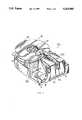
- FIG. 1is a perspective view, partially broken away, of a multi-disk, magneto-optical storage system which can use the device of the present invention
- FIG. 2is a side elevated view, partially broken away of the head assembly and disk of FIG. 1;
- FIG. 1shows a multi-disk magneto-optical storage system ("M-O system") 10 comprising a optical assembly 20, a disk assembly 30, and a carriage assembly 40 firmly secured on a mounting base 5.
- M-O systemmulti-disk magneto-optical storage system
- the optical assembly 20comprises a single stationary laser source and detector 21 emitting a lightbeam, generally indicated by a broken line 22.
- the directed lightbeam 22is used to write and read information on the storage media of the disk assembly 30.
- the lightbeam 22is concurrently distributed, by means of various stationary and movable mirrors, for example a mirrored galvanometer 23, polarizers, beam splitters, lenses, and prisms, to the various surfaces the disk assembly 30.
- the lightbeam 22is reflected to essentially retrace its path back to the detector 21.
- the disk assembly 30comprises a plurality of double sided disks 31 axially spaced about a rotatably mounted spindle 32.
- the M-O system 10has, for example, six double sided disks 31.
- the top surface of the top disk and the bottom surface of the bottom diskare generally not used for information storage purposes.
- the M-O system 10has, by way of example, five pairs of opposingly facing data surfaces for recording information.
- the disk assembly 30is compatible with a so called "51/4 inch" form factor drive.
- form factormeans the external outline, (height, width and length), required for the drive assembly including its on-board control electronics.
- the recording media on the surfaces of the disks 31, as will be discussed in greater detail herein,are layered on a circular substrate entirely by thin-film forming techniques such as sputtering or vacuum deposition.
- the feature which is common to the recording media of an M-O systemis a layer of magnetic material that has the axis of magnetization perpendicular to the amorphous thin-film surface and for which the Kerr effect is great.
- the substrateis generally "pre-formatted" with microscopic surface relief 33 in the form of, for example, tracking grooves or servo-sampled pits to provide a physical structure for storing information.
- the grooves 33when used for storing randomly accessible information, are usually formed in closely spaced concentric circles, commonly known as tracks.
- the apparatus of the inventionas disclosed herein, can also be used with substrates grooved in a spiral configuration. Spirally grooved disks are typically used with systems storing primarily sequentially accessible information.
- each of the head assemblies 66comprises an objective lens 67 for focusing the lightbeam 22.
- the head assembly 66also includes a slider 83 having a miniature magnetic coil, not shown, for polarizing the recording media of the disk 31, and a microscopic optical aperture 84 for the focused lightbeam 22 to pass through.
- a triangular or prismatically shaped mirrorhereinafter referred to as folding prism 90.
- Each prism 90has two planar reflective surfaces 91 arranged at ninety degrees with respect to each other for directing the lightbeam 22 at one of the objective lens 67 which focuses the lightbeam 22 onto the surface of the disk 31.
- the laser source 21 of the optical assembly 20typically a laser diode, emits a diverging lightbeam 22 which is collected and collimated by a lens and made circular by a prism.
- This circular lightbeam 22is selectively aimed by various optical components, including lenses, mirrors, beam splitters, and prisms, at the reflective surface 91 of the folding prisms 90.
- the horizontal lightbeam 22is folded over into a vertical direction and directed through the objective lens 67, the optical aperture 84 in the slider 83 to be focused at the recording layer of the disks 31.
- a relatively low intensity polarized lightbeam 22is used, for example in the range of about 2.0 to 2.5 mW, depending on the rotational frequency of the spinning disks 31.
- the polarized lightbeam 22is rotated clockwise or counter-clockwise through an angle in the range of about 0.6 to 2.0 degrees at the recording layer by the Kerr effect.
- the lightbeam 22is reflected at the surface of the disk 31 to essentially retrace its path to a polarizing beam splitter and optical detector 21 for decoding the polarization-modulated lightbeam 22 into bits of information.
- the double sided disks 31are rotated at high speed, for example in the range of 2400 to 4800 revolutions per minute, by an electrical motor not shown.
- the sliders 83are low-mass, low-profile, and air-bearing designed to fly at a height in the range of about 20 to 80 microinches above the surfaces of the double sided disks 31.
- the carriage body 60is approximately positioned above a predetermined track, (commonly known as coarse seeking), and the lightbeam 22 is directed by the galvanometer 23 at the corresponding reflective surface 91 of the prisms 90.
- the lightbeam 22is deflected by the reflective surface 91 to the objective lens 67 and focused by the components of the optical assembly exactly on one of the tracks of the disks 31 (commonly known as fine seeking).
- each of the disks 31, according to the inventioncomprise a single substrate 110 having a quadri-layer structure symmetrically formed on each side surface 111 thereof.
- the active layers of the recording mediaare formed entirely as thin-film layers which provide the disks 31 with a transparent, low stiction, and asperity-controlled external surface topology compatible with the air incident lightbeam 22 and the low-flying read/write head assembly 66. That is, by using thin-film layers, the asperity or roughness of the outer surface of the disks 31 can be maintained at less than 60% of the predetermined fly height of the heads 66, nominally in the range of 20 to 80 microinches.
- the layerscomprise in order, from the substrate 110 outwards, a reflective layer 120, an optional dielectric layer 130, a recording layer 140, and a protective layer 150.
- a grooved or "pre-formatted" disk 31is prepared by: 1) molding a substrate 110 from a light weight, low warpage material, for example, polycarbonate or a similarly characterized polymers; or 2) photopolymer ("2P") replication of a substrate; or 3) chemically etching (contact printing) of a substrate made from a material such as glass or aluminum. Since the light beam 22 is air incident, and not through the substrate 110 (substrate incident), as in most conventional M-O disks, the optical quality of the disk is of minimal concern. For example, the substrate 110 does not need to be corrected for birefringence or transmittance. As an advantage of the present invention, the substrate material can be selected to optimize weight, rigidity, durability, and cost.
- the substrate 110has an outer diameter of 130 mm, to make a so called industry standard "51/4 inch" disk.
- the substrate 110is formed with a centrally located circular hole 101 for mounting the fabricated disk 31 axially about the spindle 32 of the M-O device, as shown in FIG. 3.
- the inner diameter of the hole 101is 40 mm.
- the substratehas a nominal thickness of 1.2 mm.
- Each side surface 111 of the substrate 110includes a relief in the form of a plurality of conventional concentric grooves 33, as shown not to scale in FIG. 4, commonly known as tracks.
- the grooves 33which provide a physical structure for facilitating the guiding of the lightbeam 22 during operation of the M-O device 10 are, by way of example, spaced apart about 1.0 um.
- the grooves 33have, nominally, a width of about 0.4 um, and a depth of 0.1 um.
- the profile of the grooves 33is, for example, V-shaped.
- a M-O device 10 of the type that is used for random accesstypically has a grooved geometry that is concentric, disks having grooves formed in a spiral geometry may also be used by the device according to the invention.
- each side surface 111 of the substrate 110can optionally include an annular non-grooved zone above which the head assemblies 66 are positioned during loading and unloading to improve reliability.
- the sliders 83are loaded or unloaded, they are positioned above the non-grooved zone.
- the disk 31can be used with a M-O device 10 of the type that use static contact start/stop head loading techniques. With static contact start/stop loading the sliders 83 are resting or sliding on the surfaces of the disks 31 until the disks 31 attain sufficient angular velocity to permit the sliders 83 to fly at their normal operational height above the surface.
- each side of the thus grooved surface 111 of the substrate 110Built up on each side of the thus grooved surface 111 of the substrate 110 are the various thin-film layers that comprise the active recording media. Since each side surface 111 of the substrate 110 is built up as a mirror image of the other, the various layers will only be described with respect to one of the side surfaces 111.
- the layersare generally applied by conventional, thin-film coating techniques such as vacuum deposition or sputtering. Such techniques, are well known in the art, and therefore do not require further description herein.
- the reflective layer 120is formed of a metal, for example, preferably an aluminum alloy.
- the purpose of the reflective layer 120is to reflect the lightbeam 22 back through the recording layer 130, where destructive interference of the incident polarization enhances light absorption, thereby enhancing media sensitivity and Kerr rotation.
- the thickness of the reflective layer 120can be adjusted to tune and optimize the thermal characteristics of the media. It has been determined that good reflective results can be obtained by having the reflective layer 120 be in the range of about 200 to 500 Angstrom thick for a polycarbonate substrate 110. However, other thicknesses may be optimal for a substrate 110 made of a glass or metallic material.
- the transparent dielectric layer 130is formed on the reflective layer 120 and typically comprises aluminum nitride or silicon nitride.
- the purpose of the dielectric layeris to enhance the Kerr effect and also to provide a corrosive resistant boundary between the reflective layer 120 and the recording layer 140. Good isolating results have been obtained with a dielectric layer 130 having a thickness in the range of about 150 to 400 Angstrom thick.
- the recording layer 140is formed on the dielectric layer 130.
- the recording layergenerally comprises a vertically oriented, amorphous magnetic material, for example, a rare-earth transition-metal alloy, such as Tb-Fe-Co.
- the purpose of the recording layeris to provide the media with the capability to store information in vertically biased magnetic domains.
- the domainshave a length in the circumferential direction in the range of about 0.6 to 0.9 micrometer.
- the recording layer 140is about 150 to 500 Angstrom thick, although other thin-film thicknesses may be appropriate for amorphous magnetic materials of different composition.
- the protective layer 150is formed on the recording layer 140.
- One purpose of the protective layer 150is to prevent corrosion of the recording layer 140.
- the surface of the protective layer 150must be compatible with the low-mass, air-bearing sliders 83 comprising, for example, an aluminum oxide, titanium carbide (Al 2 O 3 -TiC) material.
- Al 2 O 3 -TiCaluminum oxide, titanium carbide
- Experimentation with various materialshas revealed that not all known protective coatings for M-O medium, for example, aluminum nitride, silicon carbide, or silicon dioxide, would allow the low-mass sliders 83 to fly reliably at low-heights, for example in the range of 20 to 80 microinches.
- the preferred material for the protective layer 150compatible with the low-mass air-bearing sliders 83 is silicon nitride (Si 3 N 4 ).
- the protective layer 150 of silicon nitride having low-stiction and minimal asperityhas a thickness in the range of about 400 to 800 Angstrom.
- the double-sided single substrate disk according to the present inventioninclude a low-profile magneto-optical media which can used with a reduced height multi-disk stack. Also, the disk can be made with less steps, and with lower cost materials.
- the double-sided, air-incident substrate as disclosed hereinis of reduced weight and therefore consumes less power during operation. Furthermore, the low-stiction, asperity-controlled disk is compatible with a dynamically loadable flying read/write head, permitting greater recording densities.
Landscapes
- Physics & Mathematics (AREA)
- Optics & Photonics (AREA)
Abstract
Description
Claims (24)
Priority Applications (3)
| Application Number | Priority Date | Filing Date | Title |
|---|---|---|---|
| US07/847,526US5202880A (en) | 1992-03-06 | 1992-03-06 | Double-sided magneto-optical media for a multi-disk storage device |
| US08/020,515US5470627A (en) | 1992-03-06 | 1993-02-22 | Double-sided optical media for a disk storage device |
| PCT/US1993/002511WO1993018512A1 (en) | 1992-03-06 | 1993-03-04 | Double-sided magneto-optical media for a multi-disk storage device |
Applications Claiming Priority (1)
| Application Number | Priority Date | Filing Date | Title |
|---|---|---|---|
| US07/847,526US5202880A (en) | 1992-03-06 | 1992-03-06 | Double-sided magneto-optical media for a multi-disk storage device |
Related Child Applications (1)
| Application Number | Title | Priority Date | Filing Date |
|---|---|---|---|
| US08/020,515Continuation-In-PartUS5470627A (en) | 1992-03-06 | 1993-02-22 | Double-sided optical media for a disk storage device |
Publications (1)
| Publication Number | Publication Date |
|---|---|
| US5202880Atrue US5202880A (en) | 1993-04-13 |
Family
ID=25300849
Family Applications (1)
| Application Number | Title | Priority Date | Filing Date |
|---|---|---|---|
| US07/847,526Expired - LifetimeUS5202880A (en) | 1992-03-06 | 1992-03-06 | Double-sided magneto-optical media for a multi-disk storage device |
Country Status (2)
| Country | Link |
|---|---|
| US (1) | US5202880A (en) |
| WO (1) | WO1993018512A1 (en) |
Cited By (42)
| Publication number | Priority date | Publication date | Assignee | Title |
|---|---|---|---|---|
| US5307336A (en)* | 1992-03-06 | 1994-04-26 | Digital Equipment Corporation | Multi-disk optical storage system |
| US5327416A (en)* | 1993-02-22 | 1994-07-05 | Lee Neville K | Surface selection mechanism for optical storage system |
| US5359579A (en)* | 1992-07-10 | 1994-10-25 | Nec Corporation | Magneto-optical recording method and medium for recording three-value information |
| US5392262A (en)* | 1992-12-31 | 1995-02-21 | International Business Machines Corporation | Two-sided optical disks having recording layers disposed close to outer surfaces and spaced axially apart a greater distance and devices for using the disks |
| US5470627A (en)* | 1992-03-06 | 1995-11-28 | Quantum Corporation | Double-sided optical media for a disk storage device |
| WO1996005052A1 (en)* | 1994-08-10 | 1996-02-22 | The Carborundum Company | Ceramic substrates and magnetic data storage components |
| US5533001A (en)* | 1990-01-31 | 1996-07-02 | Sony Corporation | Magneto-optical disk system with specified thickness for protective layer relative to the numerical aperture of the objective lens |
| US5572491A (en)* | 1993-12-28 | 1996-11-05 | Sony Corporation | Magneto-optical recording device capable of recording two magneto-optical discs |
| US5726969A (en)* | 1994-12-28 | 1998-03-10 | Matsushita Electric Industrial Co., Ltd. | Optical recording medium having dual information surfaces |
| US5764621A (en)* | 1994-10-31 | 1998-06-09 | Daewoo Electronics Co., Ltd. | Optical disc with a plurality of recording layers |
| US5793584A (en)* | 1996-12-13 | 1998-08-11 | Terastor Corporation | Device and method for electrostatically cleaning a disk mounted in a removable cartridge |
| US5828482A (en)* | 1997-02-05 | 1998-10-27 | Terastor Corporation | Apparatus and method for directing a beam of light to a surface of an optical disk |
| US5881042A (en)* | 1996-05-01 | 1999-03-09 | Terastor Corporation | Flying head with solid immersion lens partially mounted on a slider |
| US5910932A (en)* | 1991-09-11 | 1999-06-08 | Sony Corporation | Optical disk and optical disk system with numerical aperture of objective lens related to protective layer thickness of optical disk |
| US5936928A (en)* | 1996-10-01 | 1999-08-10 | Terastor Corporation | Multilayer media and use with flying head having solid immersion lens |
| US5963532A (en)* | 1998-01-21 | 1999-10-05 | Terastor Corporation | Polarization rotation and phase compensation in near-field electro-optical system |
| US6002663A (en)* | 1997-04-17 | 1999-12-14 | Imation Corp. | Hubless optical disc having low radial runout and method of manufacture |
| US6009064A (en)* | 1997-11-05 | 1999-12-28 | Terastor Corporation | Optical head having dielectric transition layer in near-field optical storage system |
| US6104675A (en)* | 1998-02-20 | 2000-08-15 | Maxoptix Corporation | Method and apparatus for reading and writing magneto-optical media |
| US6106919A (en)* | 1998-04-16 | 2000-08-22 | Digital Papyrus Corporation | Phase change media compatible with air bearing flying head |
| US6139307A (en)* | 1998-07-23 | 2000-10-31 | Imation Corp. | Assembly for molding optical data storage disks formatted on both sides |
| EP0977192A4 (en)* | 1997-04-14 | 2000-11-15 | Toray Industries | Optical recording device and optical recording medium |
| US6154441A (en)* | 1997-04-17 | 2000-11-28 | Imation Corp. | Method for centering a hub in an optical disc, and an optical storage system using such disc |
| US6160769A (en)* | 1997-08-07 | 2000-12-12 | Hitachi Maxell, Ltd. | Optical recording medium and optical recording device |
| US6172944B1 (en) | 1998-02-20 | 2001-01-09 | Maxoptix Corporation | Magneto-optical recording apparatus with magnetic head decoupled from objective lens focus actuator |
| US6172945B1 (en) | 1998-09-04 | 2001-01-09 | Maxoptix Corporation | Double-sided magneto-optical recording disk |
| US6226233B1 (en) | 1996-07-30 | 2001-05-01 | Seagate Technology, Inc. | Magneto-optical system utilizing MSR media |
| SG80620A1 (en)* | 1998-09-18 | 2001-05-22 | Samsung Electronics Co Ltd | Near-field optical storage medium and optical data storage system therefor |
| US6243350B1 (en) | 1996-05-01 | 2001-06-05 | Terastor Corporation | Optical storage systems with flying optical heads for near-field recording and reading |
| US6266315B1 (en) | 1997-11-22 | 2001-07-24 | Samsung Electronics Co., Ltd. | Catadioptric optical system, optical pickup and optical disk drive employing the same, and optical disk |
| US6270696B1 (en) | 1996-06-03 | 2001-08-07 | Terastor Corporation | Method of fabricating and integrating an optical assembly into a flying head |
| US6324130B1 (en) | 1999-01-21 | 2001-11-27 | Maxoptix Corporation | Disc drive suspension and head |
| US6330209B1 (en) | 1998-02-20 | 2001-12-11 | Maxoptix Corporation | Load and unload control for magneto-optical disk drive |
| US20020068198A1 (en)* | 2000-12-05 | 2002-06-06 | Kerfeld Donald J. | Data storage media |
| US20020136146A1 (en)* | 1998-09-18 | 2002-09-26 | Lee Chul-Woo | Near-field optical storage medium and optical data storage system therefor |
| US20030028847A1 (en)* | 2001-06-01 | 2003-02-06 | Keeler Stanton M. | Error correction code block format |
| US6678238B1 (en) | 1999-12-29 | 2004-01-13 | Imation Corp. | Mold for manufacturing double-sided disk shaped articles for storing data |
| US6715200B2 (en) | 1999-02-12 | 2004-04-06 | General Electric Company | Methods for making data storage media |
| US6821460B2 (en) | 2001-07-16 | 2004-11-23 | Imation Corp. | Two-sided replication of data storage media |
| US7055163B2 (en)* | 2000-12-08 | 2006-05-30 | Sharp Kabushiki Kaisha | Disc cartridge and disc drive |
| US7179551B2 (en) | 1999-02-12 | 2007-02-20 | General Electric Company | Poly(arylene ether) data storage media |
| US10969560B2 (en) | 2017-05-04 | 2021-04-06 | Lightpath Technologies, Inc. | Integrated optical assembly and manufacturing the same |
Citations (11)
| Publication number | Priority date | Publication date | Assignee | Title |
|---|---|---|---|---|
| US4441179A (en)* | 1979-01-15 | 1984-04-03 | Discovision Associates | Optical video disc structure |
| US4658392A (en)* | 1984-07-11 | 1987-04-14 | Polygram Gmbh | Optically readable, high storage density, information carrier |
| US4893910A (en)* | 1988-03-16 | 1990-01-16 | Hewlett-Packard Company | Magneto-optical recording system having medium with domainless control layer |
| US5059473A (en)* | 1988-02-15 | 1991-10-22 | Sharp Kabushiki Kaisha | Optical recording medium and manufacturing method thereof |
| US5087340A (en)* | 1989-12-01 | 1992-02-11 | Pioneer Electronic Corporation | Method of making magneto-optical recording disk |
| US5093174A (en)* | 1989-07-04 | 1992-03-03 | Teijin Limited | Optical recording medium |
| US5094925A (en)* | 1989-06-30 | 1992-03-10 | Sharp Kabushiki Kaisha | Opto-magnetic recording medium |
| US5100741A (en)* | 1984-09-12 | 1992-03-31 | Seiko Epson Corporation | Magneto-optic recording systems |
| US5109377A (en)* | 1988-08-22 | 1992-04-28 | Fuji Photo Film Co., Ltd. | Magneto-optical recording medium and method of producing the same |
| US5112701A (en)* | 1988-03-25 | 1992-05-12 | Ricoh Company, Ltd. | Magneto-optic recording media and process for producing the same |
| US5143797A (en)* | 1988-08-30 | 1992-09-01 | Mitsubishi Denki Kabushiki Kaisha | Magneto-optic recording medium |
Family Cites Families (6)
| Publication number | Priority date | Publication date | Assignee | Title |
|---|---|---|---|---|
| US5105408A (en)* | 1988-05-12 | 1992-04-14 | Digital Equipment Corporation | Optical head with flying lens |
| JPH03225650A (en)* | 1990-01-31 | 1991-10-04 | Sony Corp | Optical disk system |
| JPH03248351A (en)* | 1990-02-23 | 1991-11-06 | Sharp Corp | Magneto-optical recording medium and magnetic recording/reproducing device using the same |
| US5353278A (en)* | 1990-05-08 | 1994-10-04 | Sharp Kabushiki Kaisha | Magneto-optical disk and method of manufacturing the same |
| CA2044427C (en)* | 1990-06-13 | 1997-02-11 | Junichiro Nakayama | Magneto-optical disk and manufacturing methods thereof |
| CA2046178C (en)* | 1990-07-05 | 1999-11-09 | Junichiro Nakayama | Magneto-optical disk with lubricant film |
- 1992
- 1992-03-06USUS07/847,526patent/US5202880A/ennot_activeExpired - Lifetime
- 1993
- 1993-03-04WOPCT/US1993/002511patent/WO1993018512A1/enunknown
Patent Citations (11)
| Publication number | Priority date | Publication date | Assignee | Title |
|---|---|---|---|---|
| US4441179A (en)* | 1979-01-15 | 1984-04-03 | Discovision Associates | Optical video disc structure |
| US4658392A (en)* | 1984-07-11 | 1987-04-14 | Polygram Gmbh | Optically readable, high storage density, information carrier |
| US5100741A (en)* | 1984-09-12 | 1992-03-31 | Seiko Epson Corporation | Magneto-optic recording systems |
| US5059473A (en)* | 1988-02-15 | 1991-10-22 | Sharp Kabushiki Kaisha | Optical recording medium and manufacturing method thereof |
| US4893910A (en)* | 1988-03-16 | 1990-01-16 | Hewlett-Packard Company | Magneto-optical recording system having medium with domainless control layer |
| US5112701A (en)* | 1988-03-25 | 1992-05-12 | Ricoh Company, Ltd. | Magneto-optic recording media and process for producing the same |
| US5109377A (en)* | 1988-08-22 | 1992-04-28 | Fuji Photo Film Co., Ltd. | Magneto-optical recording medium and method of producing the same |
| US5143797A (en)* | 1988-08-30 | 1992-09-01 | Mitsubishi Denki Kabushiki Kaisha | Magneto-optic recording medium |
| US5094925A (en)* | 1989-06-30 | 1992-03-10 | Sharp Kabushiki Kaisha | Opto-magnetic recording medium |
| US5093174A (en)* | 1989-07-04 | 1992-03-03 | Teijin Limited | Optical recording medium |
| US5087340A (en)* | 1989-12-01 | 1992-02-11 | Pioneer Electronic Corporation | Method of making magneto-optical recording disk |
Cited By (79)
| Publication number | Priority date | Publication date | Assignee | Title |
|---|---|---|---|---|
| US5757733A (en)* | 1990-01-31 | 1998-05-26 | Sony Corporation | Optical disc system having an objective lens with a numerical aperture related to the thickness of the protective layer |
| US5533001A (en)* | 1990-01-31 | 1996-07-02 | Sony Corporation | Magneto-optical disk system with specified thickness for protective layer relative to the numerical aperture of the objective lens |
| US5910932A (en)* | 1991-09-11 | 1999-06-08 | Sony Corporation | Optical disk and optical disk system with numerical aperture of objective lens related to protective layer thickness of optical disk |
| US5470627A (en)* | 1992-03-06 | 1995-11-28 | Quantum Corporation | Double-sided optical media for a disk storage device |
| US5307336A (en)* | 1992-03-06 | 1994-04-26 | Digital Equipment Corporation | Multi-disk optical storage system |
| US5359579A (en)* | 1992-07-10 | 1994-10-25 | Nec Corporation | Magneto-optical recording method and medium for recording three-value information |
| US5392262A (en)* | 1992-12-31 | 1995-02-21 | International Business Machines Corporation | Two-sided optical disks having recording layers disposed close to outer surfaces and spaced axially apart a greater distance and devices for using the disks |
| US5420834A (en)* | 1992-12-31 | 1995-05-30 | International Business Machines Corporation | Optical disk recorders using disks coatings close to outer surfaces with optical path extending through a thick transparent substrate |
| US5327416A (en)* | 1993-02-22 | 1994-07-05 | Lee Neville K | Surface selection mechanism for optical storage system |
| US5572491A (en)* | 1993-12-28 | 1996-11-05 | Sony Corporation | Magneto-optical recording device capable of recording two magneto-optical discs |
| WO1996005052A1 (en)* | 1994-08-10 | 1996-02-22 | The Carborundum Company | Ceramic substrates and magnetic data storage components |
| US5764621A (en)* | 1994-10-31 | 1998-06-09 | Daewoo Electronics Co., Ltd. | Optical disc with a plurality of recording layers |
| US6934237B2 (en) | 1994-12-28 | 2005-08-23 | Matsushita Electric Industrial Co., Ltd. | Optical recording medium having dual information surfaces |
| US6031813A (en)* | 1994-12-28 | 2000-02-29 | Matsushita Electric Industrial Co., Ltd. | Optical recording medium having dual information surfaces |
| US5878018A (en)* | 1994-12-28 | 1999-03-02 | Matsushita Electric Industrial Co., Ltd. | Optical recording medium having dual information surfaces |
| US7272104B2 (en) | 1994-12-28 | 2007-09-18 | Matsushita Electric Industrial Co., Ltd. | Optical recording medium having dual information surfaces |
| US5726969A (en)* | 1994-12-28 | 1998-03-10 | Matsushita Electric Industrial Co., Ltd. | Optical recording medium having dual information surfaces |
| US6947366B2 (en) | 1994-12-28 | 2005-09-20 | Matsushita Electric Industrial Co., Ltd. | Optical recording medium having dual information surfaces |
| US6737144B2 (en) | 1994-12-28 | 2004-05-18 | Matsushita Electric Industrial Co., Ltd. | Optical recording medium having dual information surfaces |
| US6934238B2 (en) | 1994-12-28 | 2005-08-23 | Matsushita Electric Industrial Co., Ltd. | Optical recording medium having dual information surfaces |
| US20050163025A1 (en)* | 1994-12-28 | 2005-07-28 | Matsushita Electric Industrial Co., Ltd. | Optical recording medium having dual information surfaces |
| US6952391B2 (en) | 1994-12-28 | 2005-10-04 | Matsushita Electric Industrial Co., Ltd. | Optical recording medium having dual information surfaces |
| US6280812B1 (en) | 1994-12-28 | 2001-08-28 | Matsushita Electric Industrial Co., Ltd. | Optical recording medium having dual information surfaces |
| US6489002B2 (en) | 1994-12-28 | 2002-12-03 | Matsushita Electric Industrial Co., Ltd. | Optical recording medium having dual information surfaces |
| US20040160881A1 (en)* | 1994-12-28 | 2004-08-19 | Matsushita Electric Industrial Co., Ltd. | Optical recording medium having dual information surfaces |
| US20040160882A1 (en)* | 1994-12-28 | 2004-08-19 | Matsushita Electric Industrial Co., Ltd. | Optical recording medium having dual information surfaces |
| US20040156296A1 (en)* | 1994-12-28 | 2004-08-12 | Matsushita Electric Industrial Co., Ltd. | Optical recording medium having dual information surfaces |
| US6143426A (en)* | 1994-12-28 | 2000-11-07 | Matsushita Electric Industrial Co., Ltd. | Optical recording medium having dual information surfaces |
| US20040156305A1 (en)* | 1994-12-28 | 2004-08-12 | Matsushita Electric Industrial Co., Ltd. | Optical recording medium having dual information surfaces |
| US6243350B1 (en) | 1996-05-01 | 2001-06-05 | Terastor Corporation | Optical storage systems with flying optical heads for near-field recording and reading |
| US20040202055A1 (en)* | 1996-05-01 | 2004-10-14 | Terastor Corporation, A California Corporation | Disk cartridge for optical disk drives |
| US6449221B1 (en) | 1996-05-01 | 2002-09-10 | Terastor Corporation | Storage media for optical storage systems |
| US6055222A (en)* | 1996-05-01 | 2000-04-25 | Terastor Corporation | Near field optical head having a solid immersion lens that is fixed relative to an objective lens |
| US5881042A (en)* | 1996-05-01 | 1999-03-09 | Terastor Corporation | Flying head with solid immersion lens partially mounted on a slider |
| US6270696B1 (en) | 1996-06-03 | 2001-08-07 | Terastor Corporation | Method of fabricating and integrating an optical assembly into a flying head |
| US6582630B2 (en) | 1996-06-03 | 2003-06-24 | Amit Jain | Method of fabricating and integrating an optical assembly into a flying head |
| US6226233B1 (en) | 1996-07-30 | 2001-05-01 | Seagate Technology, Inc. | Magneto-optical system utilizing MSR media |
| US5936928A (en)* | 1996-10-01 | 1999-08-10 | Terastor Corporation | Multilayer media and use with flying head having solid immersion lens |
| US5793584A (en)* | 1996-12-13 | 1998-08-11 | Terastor Corporation | Device and method for electrostatically cleaning a disk mounted in a removable cartridge |
| US5828482A (en)* | 1997-02-05 | 1998-10-27 | Terastor Corporation | Apparatus and method for directing a beam of light to a surface of an optical disk |
| EP0977192A4 (en)* | 1997-04-14 | 2000-11-15 | Toray Industries | Optical recording device and optical recording medium |
| US6002663A (en)* | 1997-04-17 | 1999-12-14 | Imation Corp. | Hubless optical disc having low radial runout and method of manufacture |
| US6154441A (en)* | 1997-04-17 | 2000-11-28 | Imation Corp. | Method for centering a hub in an optical disc, and an optical storage system using such disc |
| US6382955B1 (en) | 1997-04-17 | 2002-05-07 | Imation Corp. | Disc molding apparatus for hubless optical disc having low radial runout |
| US6490242B1 (en) | 1997-04-29 | 2002-12-03 | Brian T. Bonn | Disk cartridge with dual housing structure |
| US6160769A (en)* | 1997-08-07 | 2000-12-12 | Hitachi Maxell, Ltd. | Optical recording medium and optical recording device |
| US6366541B1 (en) | 1997-08-07 | 2002-04-02 | Hitachi Maxell, Ltd. | Optical recording medium with solid protective layer having self-lubricating property |
| US6111840A (en)* | 1997-08-18 | 2000-08-29 | Terastor Corporation | Reducing phase distortion in a near-field optical data storage system |
| US6009064A (en)* | 1997-11-05 | 1999-12-28 | Terastor Corporation | Optical head having dielectric transition layer in near-field optical storage system |
| US6266315B1 (en) | 1997-11-22 | 2001-07-24 | Samsung Electronics Co., Ltd. | Catadioptric optical system, optical pickup and optical disk drive employing the same, and optical disk |
| US5963532A (en)* | 1998-01-21 | 1999-10-05 | Terastor Corporation | Polarization rotation and phase compensation in near-field electro-optical system |
| US6172944B1 (en) | 1998-02-20 | 2001-01-09 | Maxoptix Corporation | Magneto-optical recording apparatus with magnetic head decoupled from objective lens focus actuator |
| US6104675A (en)* | 1998-02-20 | 2000-08-15 | Maxoptix Corporation | Method and apparatus for reading and writing magneto-optical media |
| US6330209B1 (en) | 1998-02-20 | 2001-12-11 | Maxoptix Corporation | Load and unload control for magneto-optical disk drive |
| US6106919A (en)* | 1998-04-16 | 2000-08-22 | Digital Papyrus Corporation | Phase change media compatible with air bearing flying head |
| US6139307A (en)* | 1998-07-23 | 2000-10-31 | Imation Corp. | Assembly for molding optical data storage disks formatted on both sides |
| US6172945B1 (en) | 1998-09-04 | 2001-01-09 | Maxoptix Corporation | Double-sided magneto-optical recording disk |
| SG80620A1 (en)* | 1998-09-18 | 2001-05-22 | Samsung Electronics Co Ltd | Near-field optical storage medium and optical data storage system therefor |
| US7054259B2 (en) | 1998-09-18 | 2006-05-30 | Samsung Electronics Co., Ltd. | Near-field optical storage medium and optical data storage system therefor |
| US6621787B1 (en) | 1998-09-18 | 2003-09-16 | Samsung Electronics Co Ltd | Optical storage medium having protective layer thicker than wavelength of useable light source |
| US6798732B2 (en) | 1998-09-18 | 2004-09-28 | Samsung Electronics Co., Ltd. | Near-field optical storage medium and optical data storage system therefor |
| US20020136146A1 (en)* | 1998-09-18 | 2002-09-26 | Lee Chul-Woo | Near-field optical storage medium and optical data storage system therefor |
| US20040218500A1 (en)* | 1998-09-18 | 2004-11-04 | Samsung Electronics Co., Ltd. | Near-field optical storage medium and optical data storage system therefor |
| US7362693B2 (en) | 1998-09-18 | 2008-04-22 | Samsung Electronics Co., Ltd. | Near-field optical storage medium and optical data storage system therefor |
| US6885625B2 (en) | 1998-09-18 | 2005-04-26 | Samsung Electronics Co., Ltd. | Near-field optical storage medium and optical data storage system therefor |
| US6324130B1 (en) | 1999-01-21 | 2001-11-27 | Maxoptix Corporation | Disc drive suspension and head |
| US7179551B2 (en) | 1999-02-12 | 2007-02-20 | General Electric Company | Poly(arylene ether) data storage media |
| US7087290B2 (en) | 1999-02-12 | 2006-08-08 | General Electric | Data storage media utilizing a substrate including a plastic resin layer, and method thereof |
| US6715200B2 (en) | 1999-02-12 | 2004-04-06 | General Electric Company | Methods for making data storage media |
| US6752952B2 (en) | 1999-02-12 | 2004-06-22 | General Electric Company | Embossing methods |
| US6678238B1 (en) | 1999-12-29 | 2004-01-13 | Imation Corp. | Mold for manufacturing double-sided disk shaped articles for storing data |
| US20040117812A1 (en)* | 1999-12-29 | 2004-06-17 | Plourde Douglas R. | Mold for manufacturing double-sided disk shaped articles for storing data |
| US20020068198A1 (en)* | 2000-12-05 | 2002-06-06 | Kerfeld Donald J. | Data storage media |
| WO2002046860A3 (en)* | 2000-12-05 | 2003-08-07 | Imation Corp | Data storage media |
| US7055163B2 (en)* | 2000-12-08 | 2006-05-30 | Sharp Kabushiki Kaisha | Disc cartridge and disc drive |
| US20030028847A1 (en)* | 2001-06-01 | 2003-02-06 | Keeler Stanton M. | Error correction code block format |
| US6910174B2 (en)* | 2001-06-01 | 2005-06-21 | Dphi Acquisitions, Inc. | Error correction code block format |
| US6821460B2 (en) | 2001-07-16 | 2004-11-23 | Imation Corp. | Two-sided replication of data storage media |
| US10969560B2 (en) | 2017-05-04 | 2021-04-06 | Lightpath Technologies, Inc. | Integrated optical assembly and manufacturing the same |
Also Published As
| Publication number | Publication date |
|---|---|
| WO1993018512A1 (en) | 1993-09-16 |
Similar Documents
| Publication | Publication Date | Title |
|---|---|---|
| US5202880A (en) | Double-sided magneto-optical media for a multi-disk storage device | |
| US5470627A (en) | Double-sided optical media for a disk storage device | |
| US6724694B2 (en) | Disk mastering based on near-field optical systems | |
| JP2614389B2 (en) | Optical storage device and optical head device | |
| US6366541B1 (en) | Optical recording medium with solid protective layer having self-lubricating property | |
| US5889641A (en) | Magneto-resistive magneto-optical head | |
| US20010055702A1 (en) | Self-lubricating layer for data storage devices | |
| US6256267B1 (en) | Method for reading and writing magneto-optical media | |
| JP2002508869A (en) | High capacity magneto-optical data storage system. | |
| WO1998049675A1 (en) | Electro-optical storage system with flying head for near-field recording and reading | |
| US5784343A (en) | Magneto-optical recording and/or reproducing apparatus having a plurality of optical systems | |
| US6430114B1 (en) | Self-lubricating layer for a data storage disk | |
| US5640377A (en) | Rotation information detecting apparatus and method | |
| JPS61145746A (en) | optical recording and playback medium | |
| US6172945B1 (en) | Double-sided magneto-optical recording disk | |
| US6044043A (en) | Magneto-optical head capable of operation under inclination of the disc | |
| KR100447368B1 (en) | Recording and reproducing device, disk cartridge, and optical disk device | |
| US5101385A (en) | Magneto-optical information storage system for flexible media having maximum overwrite efficiency | |
| Birukawa et al. | The optical design for near field optical approach using solid immersion lens for high density recording | |
| JP2002260367A (en) | Recording / reproducing device and disk cartridge | |
| Ogawa et al. | Magneto-optical recording enhanced by magnetic recording techniques | |
| KR20000057954A (en) | Optical recording medium | |
| JPH0417141A (en) | Magneto-optical memory element and its manufacturing method | |
| JP2002260265A (en) | Recording / reproducing device and disk cartridge | |
| EP1202266A1 (en) | Magneto-optical disk |
Legal Events
| Date | Code | Title | Description |
|---|---|---|---|
| AS | Assignment | Owner name:DIGITAL EQUIPMENT CORPORATION, MASSACHUSETTS Free format text:ASSIGNMENT OF ASSIGNORS INTEREST.;ASSIGNORS:LEE, NEVILLE K.;TAN, BRIAN;REEL/FRAME:006064/0836 Effective date:19920205 | |
| STCF | Information on status: patent grant | Free format text:PATENTED CASE | |
| CC | Certificate of correction | ||
| AS | Assignment | Owner name:QUANTUM CORPORATION, CALIFORNIA Free format text:ASSIGNMENT OF ASSIGNORS INTEREST;ASSIGNOR:DIGITAL EQUIPMENT CORPORATION;REEL/FRAME:007249/0263 Effective date:19941205 | |
| FEPP | Fee payment procedure | Free format text:PAYOR NUMBER ASSIGNED (ORIGINAL EVENT CODE: ASPN); ENTITY STATUS OF PATENT OWNER: LARGE ENTITY | |
| FPAY | Fee payment | Year of fee payment:4 | |
| FPAY | Fee payment | Year of fee payment:8 | |
| REMI | Maintenance fee reminder mailed | ||
| AS | Assignment | Owner name:MAXTOR CORPORATION, CALIFORNIA Free format text:ASSIGNMENT OF ASSIGNORS INTEREST;ASSIGNOR:QUANTUM CORPORATION;REEL/FRAME:012653/0726 Effective date:20010724 | |
| FPAY | Fee payment | Year of fee payment:12 | |
| AS | Assignment | Owner name:WELLS FARGO BANK, NATIONAL ASSOCIATION, AS COLLATERAL AGENT AND SECOND PRIORITY REPRESENTATIVE, CALIFORNIA Free format text:SECURITY AGREEMENT;ASSIGNORS:MAXTOR CORPORATION;SEAGATE TECHNOLOGY LLC;SEAGATE TECHNOLOGY INTERNATIONAL;REEL/FRAME:022757/0017 Effective date:20090507 Owner name:JPMORGAN CHASE BANK, N.A., AS ADMINISTRATIVE AGENT AND FIRST PRIORITY REPRESENTATIVE, NEW YORK Free format text:SECURITY AGREEMENT;ASSIGNORS:MAXTOR CORPORATION;SEAGATE TECHNOLOGY LLC;SEAGATE TECHNOLOGY INTERNATIONAL;REEL/FRAME:022757/0017 Effective date:20090507 Owner name:JPMORGAN CHASE BANK, N.A., AS ADMINISTRATIVE AGENT Free format text:SECURITY AGREEMENT;ASSIGNORS:MAXTOR CORPORATION;SEAGATE TECHNOLOGY LLC;SEAGATE TECHNOLOGY INTERNATIONAL;REEL/FRAME:022757/0017 Effective date:20090507 Owner name:WELLS FARGO BANK, NATIONAL ASSOCIATION, AS COLLATE Free format text:SECURITY AGREEMENT;ASSIGNORS:MAXTOR CORPORATION;SEAGATE TECHNOLOGY LLC;SEAGATE TECHNOLOGY INTERNATIONAL;REEL/FRAME:022757/0017 Effective date:20090507 | |
| AS | Assignment | Owner name:SEAGATE TECHNOLOGY HDD HOLDINGS, CALIFORNIA Free format text:RELEASE;ASSIGNOR:JPMORGAN CHASE BANK, N.A., AS ADMINISTRATIVE AGENT;REEL/FRAME:025662/0001 Effective date:20110114 Owner name:MAXTOR CORPORATION, CALIFORNIA Free format text:RELEASE;ASSIGNOR:JPMORGAN CHASE BANK, N.A., AS ADMINISTRATIVE AGENT;REEL/FRAME:025662/0001 Effective date:20110114 Owner name:SEAGATE TECHNOLOGY LLC, CALIFORNIA Free format text:RELEASE;ASSIGNOR:JPMORGAN CHASE BANK, N.A., AS ADMINISTRATIVE AGENT;REEL/FRAME:025662/0001 Effective date:20110114 Owner name:SEAGATE TECHNOLOGY INTERNATIONAL, CALIFORNIA Free format text:RELEASE;ASSIGNOR:JPMORGAN CHASE BANK, N.A., AS ADMINISTRATIVE AGENT;REEL/FRAME:025662/0001 Effective date:20110114 | |
| AS | Assignment | Owner name:THE BANK OF NOVA SCOTIA, AS ADMINISTRATIVE AGENT, CANADA Free format text:SECURITY AGREEMENT;ASSIGNOR:SEAGATE TECHNOLOGY LLC;REEL/FRAME:026010/0350 Effective date:20110118 Owner name:THE BANK OF NOVA SCOTIA, AS ADMINISTRATIVE AGENT, Free format text:SECURITY AGREEMENT;ASSIGNOR:SEAGATE TECHNOLOGY LLC;REEL/FRAME:026010/0350 Effective date:20110118 | |
| AS | Assignment | Owner name:EVAULT INC. (F/K/A I365 INC.), CALIFORNIA Free format text:TERMINATION AND RELEASE OF SECURITY INTEREST IN PATENT RIGHTS;ASSIGNOR:WELLS FARGO BANK, NATIONAL ASSOCIATION, AS COLLATERAL AGENT AND SECOND PRIORITY REPRESENTATIVE;REEL/FRAME:030833/0001 Effective date:20130312 Owner name:SEAGATE TECHNOLOGY US HOLDINGS, INC., CALIFORNIA Free format text:TERMINATION AND RELEASE OF SECURITY INTEREST IN PATENT RIGHTS;ASSIGNOR:WELLS FARGO BANK, NATIONAL ASSOCIATION, AS COLLATERAL AGENT AND SECOND PRIORITY REPRESENTATIVE;REEL/FRAME:030833/0001 Effective date:20130312 Owner name:SEAGATE TECHNOLOGY LLC, CALIFORNIA Free format text:TERMINATION AND RELEASE OF SECURITY INTEREST IN PATENT RIGHTS;ASSIGNOR:WELLS FARGO BANK, NATIONAL ASSOCIATION, AS COLLATERAL AGENT AND SECOND PRIORITY REPRESENTATIVE;REEL/FRAME:030833/0001 Effective date:20130312 Owner name:SEAGATE TECHNOLOGY INTERNATIONAL, CAYMAN ISLANDS Free format text:TERMINATION AND RELEASE OF SECURITY INTEREST IN PATENT RIGHTS;ASSIGNOR:WELLS FARGO BANK, NATIONAL ASSOCIATION, AS COLLATERAL AGENT AND SECOND PRIORITY REPRESENTATIVE;REEL/FRAME:030833/0001 Effective date:20130312 | |
| AS | Assignment | Owner name:SEAGATE TECHNOLOGY PUBLIC LIMITED COMPANY, CALIFORNIA Free format text:RELEASE BY SECURED PARTY;ASSIGNOR:THE BANK OF NOVA SCOTIA;REEL/FRAME:072193/0001 Effective date:20250303 Owner name:SEAGATE TECHNOLOGY, CALIFORNIA Free format text:RELEASE BY SECURED PARTY;ASSIGNOR:THE BANK OF NOVA SCOTIA;REEL/FRAME:072193/0001 Effective date:20250303 Owner name:SEAGATE TECHNOLOGY HDD HOLDINGS, CALIFORNIA Free format text:RELEASE BY SECURED PARTY;ASSIGNOR:THE BANK OF NOVA SCOTIA;REEL/FRAME:072193/0001 Effective date:20250303 Owner name:I365 INC., CALIFORNIA Free format text:RELEASE BY SECURED PARTY;ASSIGNOR:THE BANK OF NOVA SCOTIA;REEL/FRAME:072193/0001 Effective date:20250303 Owner name:SEAGATE TECHNOLOGY LLC, CALIFORNIA Free format text:RELEASE BY SECURED PARTY;ASSIGNOR:THE BANK OF NOVA SCOTIA;REEL/FRAME:072193/0001 Effective date:20250303 Owner name:SEAGATE TECHNOLOGY INTERNATIONAL, CAYMAN ISLANDS Free format text:RELEASE BY SECURED PARTY;ASSIGNOR:THE BANK OF NOVA SCOTIA;REEL/FRAME:072193/0001 Effective date:20250303 Owner name:SEAGATE HDD CAYMAN, CAYMAN ISLANDS Free format text:RELEASE BY SECURED PARTY;ASSIGNOR:THE BANK OF NOVA SCOTIA;REEL/FRAME:072193/0001 Effective date:20250303 Owner name:SEAGATE TECHNOLOGY (US) HOLDINGS, INC., CALIFORNIA Free format text:RELEASE BY SECURED PARTY;ASSIGNOR:THE BANK OF NOVA SCOTIA;REEL/FRAME:072193/0001 Effective date:20250303 |