US5201754A - Balloon dilatation catheter with varying radiopacity - Google Patents
Balloon dilatation catheter with varying radiopacityDownload PDFInfo
- Publication number
- US5201754A US5201754AUS07/475,417US47541790AUS5201754AUS 5201754 AUS5201754 AUS 5201754AUS 47541790 AUS47541790 AUS 47541790AUS 5201754 AUS5201754 AUS 5201754A
- Authority
- US
- United States
- Prior art keywords
- catheter
- balloon
- segment
- support wire
- proximal
- Prior art date
- Legal status (The legal status is an assumption and is not a legal conclusion. Google has not performed a legal analysis and makes no representation as to the accuracy of the status listed.)
- Expired - Lifetime
Links
- 238000002399angioplastyMethods0.000claimsabstractdescription14
- 239000000463materialSubstances0.000claimsdescription19
- 210000004351coronary vesselAnatomy0.000claimsdescription14
- 238000005253claddingMethods0.000claimsdescription9
- 238000007747platingMethods0.000claimsdescription7
- 210000002376aorta thoracicAnatomy0.000claimsdescription6
- 238000002594fluoroscopyMethods0.000abstractdescription8
- 208000031481Pathologic ConstrictionDiseases0.000description16
- 239000007788liquidSubstances0.000description15
- 210000001367arteryAnatomy0.000description14
- 230000036262stenosisEffects0.000description13
- 208000037804stenosisDiseases0.000description13
- 210000003484anatomyAnatomy0.000description11
- PCHJSUWPFVWCPO-UHFFFAOYSA-NgoldChemical compound[Au]PCHJSUWPFVWCPO-UHFFFAOYSA-N0.000description10
- 239000010931goldSubstances0.000description10
- 229910052737goldInorganic materials0.000description9
- 239000003550markerSubstances0.000description9
- BASFCYQUMIYNBI-UHFFFAOYSA-NplatinumChemical compound[Pt]BASFCYQUMIYNBI-UHFFFAOYSA-N0.000description8
- 230000007704transitionEffects0.000description8
- 238000000034methodMethods0.000description7
- 229910001260Pt alloyInorganic materials0.000description4
- 229910052697platinumInorganic materials0.000description4
- 239000007787solidSubstances0.000description4
- 229910045601alloyInorganic materials0.000description3
- 239000000956alloySubstances0.000description3
- 210000004204blood vesselAnatomy0.000description3
- 238000007493shaping processMethods0.000description3
- 230000002792vascularEffects0.000description3
- 208000027418Wounds and injuryDiseases0.000description2
- 230000002411adverseEffects0.000description2
- 239000011324beadSubstances0.000description2
- 238000005219brazingMethods0.000description2
- 238000004891communicationMethods0.000description2
- 210000001105femoral arteryAnatomy0.000description2
- 238000001802infusionMethods0.000description2
- 208000014674injuryDiseases0.000description2
- 229910052751metalInorganic materials0.000description2
- 239000002184metalSubstances0.000description2
- 238000012986modificationMethods0.000description2
- 230000004048modificationEffects0.000description2
- 238000005476solderingMethods0.000description2
- 239000010935stainless steelSubstances0.000description2
- 229910001220stainless steelInorganic materials0.000description2
- 229910001020Au alloyInorganic materials0.000description1
- 229910000929Ru alloyInorganic materials0.000description1
- KJTLSVCANCCWHF-UHFFFAOYSA-NRutheniumChemical compound[Ru]KJTLSVCANCCWHF-UHFFFAOYSA-N0.000description1
- 210000000709aortaAnatomy0.000description1
- 238000013459approachMethods0.000description1
- 239000012620biological materialSubstances0.000description1
- 230000005540biological transmissionEffects0.000description1
- 239000011248coating agentSubstances0.000description1
- 238000000576coating methodMethods0.000description1
- 239000002131composite materialSubstances0.000description1
- 238000010276constructionMethods0.000description1
- 238000007887coronary angioplastyMethods0.000description1
- 230000006378damageEffects0.000description1
- 230000000694effectsEffects0.000description1
- 238000009713electroplatingMethods0.000description1
- 238000005516engineering processMethods0.000description1
- 238000002347injectionMethods0.000description1
- 239000007924injectionSubstances0.000description1
- 238000004519manufacturing processMethods0.000description1
- 238000000465mouldingMethods0.000description1
- 238000009877renderingMethods0.000description1
- 238000001356surgical procedureMethods0.000description1
- 239000010409thin filmSubstances0.000description1
- 230000008733traumaEffects0.000description1
- 210000005166vasculatureAnatomy0.000description1
Images

Classifications
- A—HUMAN NECESSITIES
- A61—MEDICAL OR VETERINARY SCIENCE; HYGIENE
- A61M—DEVICES FOR INTRODUCING MEDIA INTO, OR ONTO, THE BODY; DEVICES FOR TRANSDUCING BODY MEDIA OR FOR TAKING MEDIA FROM THE BODY; DEVICES FOR PRODUCING OR ENDING SLEEP OR STUPOR
- A61M25/00—Catheters; Hollow probes
- A61M25/10—Balloon catheters
- A61M25/104—Balloon catheters used for angioplasty
- A—HUMAN NECESSITIES
- A61—MEDICAL OR VETERINARY SCIENCE; HYGIENE
- A61M—DEVICES FOR INTRODUCING MEDIA INTO, OR ONTO, THE BODY; DEVICES FOR TRANSDUCING BODY MEDIA OR FOR TAKING MEDIA FROM THE BODY; DEVICES FOR PRODUCING OR ENDING SLEEP OR STUPOR
- A61M25/00—Catheters; Hollow probes
- A61M25/0021—Catheters; Hollow probes characterised by the form of the tubing
- A61M2025/0042—Microcatheters, cannula or the like having outside diameters around 1 mm or less
- A—HUMAN NECESSITIES
- A61—MEDICAL OR VETERINARY SCIENCE; HYGIENE
- A61M—DEVICES FOR INTRODUCING MEDIA INTO, OR ONTO, THE BODY; DEVICES FOR TRANSDUCING BODY MEDIA OR FOR TAKING MEDIA FROM THE BODY; DEVICES FOR PRODUCING OR ENDING SLEEP OR STUPOR
- A61M25/00—Catheters; Hollow probes
- A61M25/01—Introducing, guiding, advancing, emplacing or holding catheters
- A61M25/09—Guide wires
- A61M2025/091—Guide wires having a lumen for drug delivery or suction
- A—HUMAN NECESSITIES
- A61—MEDICAL OR VETERINARY SCIENCE; HYGIENE
- A61M—DEVICES FOR INTRODUCING MEDIA INTO, OR ONTO, THE BODY; DEVICES FOR TRANSDUCING BODY MEDIA OR FOR TAKING MEDIA FROM THE BODY; DEVICES FOR PRODUCING OR ENDING SLEEP OR STUPOR
- A61M25/00—Catheters; Hollow probes
- A61M25/01—Introducing, guiding, advancing, emplacing or holding catheters
- A61M25/0105—Steering means as part of the catheter or advancing means; Markers for positioning
- A61M25/0108—Steering means as part of the catheter or advancing means; Markers for positioning using radio-opaque or ultrasound markers
Definitions
- This inventionrelates to improvements in catheters for performing balloon angioplasty procedures in stenosed blood vessels.
- Balloon angioplasty procedureshave been used in recent years with increasing success in the treatment of obstructed arteries, such as the coronary arteries.
- the procedureinvolves advancing a catheter having a special balloon at its distal end to the location of the stenosis.
- the balloon portion of the catheteris placed, in its deflated condition, in the stenosis and then is inflated under high pressure to compress radially and outwardly the biological material such as plaque which forms the stenosis.
- Balloon dilatation systems of this typeare illustrated in U.S. Pat. Nos. 4,195,637 and 4,323,071. In those situations in which balloon angioplasty can be used, its successful use avoids the greater risk of complex and expensive bypass surgery.
- the low profile dilatation catheterstypically are capable of assuming relatively low cross sectional dimensions, particularly in the region of the balloon, so that when the balloon is deflated, it may be inserted, in that configuration, into a tight stenosis.
- such low profile dilatation cathetersincorporate a fixed guidewire as an integral part of the catheter.
- the guidewireforms part of or extends through the catheter and facilitates manipulation of the catheter so that it can be steered through branches in the patient's vasculature.
- the catheteris constructed and arranged to be advanceable through the patient's vascular system and can be controlled and manipulated from its proximal end so that it can be steered selectively at forks in the vascular system.
- the main body of the catheterincludes a flexible elongate hollow main shaft adapted to transmit torque from a proximal to the distal end of the catheter.
- the smaller diameter balloon support wireis attached to and extends from the distal end of the flexible hollow shaft.
- a helical springis mounted to the distal portion of the support wire.
- the dilatation balloonis attached at its proximal end to the distal portion of the main shaft and the distal end of the balloon is attached to the proximal end of the helical spring.
- An inflation/deflation portis formed in the hollow main shaft distally of the proximal balloon connection to communicate with the interior of the balloon for inflating and deflating the balloon.
- a distal segment of the catheter which projects beyond the balloonincludes the helical spring and a portion of the support wire.
- the support wireis tapered within the helical spring to provide progressively increasing flexibility in a distal direction.
- the distal end of the distal segmentis adapted to be bent to a curve and enables the catheter to be selectively directed and steered by rotating the catheter from its proximal end.
- the balloonis very thin.
- the diameter of the collapsed folded balloon portion of the catheteris very small and defines a very small profile.
- a distal portion of the catheteris formed from a highly radiopaque material so that it is readily observable under X-ray fluoroscopy.
- cathetershave included radiopaque elements in the distal segment of the catheter, distally beyond the balloon.
- small radiopaque markersmay be disposed at other locations along the catheter to enable fluoroscopic determination of the location of other portions of the catheter, such as the proximal end of the balloon.
- the helical spring in the distal segment of the catheteris formed from a highly radiopaque alloy so that it appears quite dark on the fluoroscopic screen.
- radiopaque contrast liquidprovides a highly radiopaque portion of the catheter distally of the balloon.
- itis relatively short and provides relatively little indication of the shape and configuration of the artery or arteries in which the catheter is disposed.
- the configuration of the patient's coronary anatomyis important to the physician.
- the physicianwill cause a radiographic contrast liquid to be emitted into the arteries being treated that so for a brief interval, the contour and anatomy of the arteries may be observed.
- the physicianalso activates a camera to make a permanent, replayable recording of the coronary anatomy.
- the injection of radiopaque contrast liquidalso enables the physician to examine and determine the location and nature of the stenosis or stenoses to be treated.
- the catheterproximally of the highly radiopaque distal segment, is modified to include a moderately radiopaque material extending along a substantial portion of the distal length of the catheter at and proximally of the balloon.
- the moderately radiopaque portion which trails the highly radiopaque portionthus is observable as a light but discernible shade of grey and enables the physician to observe the contours and paths of the coronary anatomy through which the balloon has been placed.
- the physicianalso may infuse radiopaque contrast liquid to observe further details of the coronary anatomy.
- the balloon support wireis coated with a thin film of radiopaque material, such as gold, to a degree sufficient to form a light grey, but discernible image on the fluoroscope.
- the portion of the balloon support wire that extends through the balloonis not rendered radiopaque so that when the physician infuses radiopaque liquid into the region of the stenosis, where the balloon is located, no radiopacity will be caused by the balloon support wire. In that configuration, all of the radiopacity will be the result of the radiopaque contrast liquid, thus providing the physician with the most detailed, unobstructed picture possible.
- a balloon dilatation catheterthat is adapted to provide a radiopaque image, in varyinq shades of intensity, of a substantial portion of the arterial anatomy both proximally of and distally of the dilatation balloon.
- a further object of the inventionis to provide a catheter of the type described in which different portions of the catheter display different intensities of radiopacity under fluoroscopic observation.
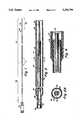
- FIG. 1is a longitudinal, fragmented illustration of the dilatation catheter
- FIG. 2is an enlarged longitudinal section of the portion of the dilatation catheter which includes the transition region from the proximal segment to the distal segment;
- FIG. 2Ais a cross-sectional illustration of the transition tube as seen along the line 2A--2A of FIG. 2;
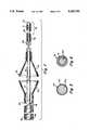
- FIG. 3is an enlarged longitudinal sectional illustration of the balloon portion and distal segment of the dilatation catheter
- FIG. 3Ais a sectional illustration of the catheter balloon as seen along the lines 3A--3A of FIG. 3;
- FIG. 3A-1is an illustration of the catheter balloon of FIG. 3A in an evacuated, collapsed configuration
- FIGS. 3A-2 and 3A-3are illustrations of the collapsed dilatation catheter balloon with its wings wrapped about the support wire in an S-shaped configuration and a C-shaped configuration, respectively;
- FIG. 3Bis a sectional illustration of the sleeve extension of the catheter when the catheter is in an inflated condition
- FIG. 3B-1is an illustration of the sleeve of FIG. 3B when in an evacuated, collapsed configuration
- FIG. 4is an enlarged sectional illustration of the juncture of the balloon and the balloon extension sleeve
- FIG. 5is a greatly enlarged cross sectional illustration of the core wire of the catheter illustrating, in exaggerated thickness, its radiopaque coating
- FIG. 6is a cross-sectional illustration, in exaggerated detail, of a support wire clad with a radiopaque material.
- FIG. 7is a cross sectional illustration, in exaggerated detail, of the distal end of a balloon catheter having a support wire with a tapered distal portion and including a segment clad in radiopaque material.
- FIG. 1illustrates a low profile balloon dilatation catheter adapted for use in the coronary arteries.
- the dilatation catheter 12is of very slender construction having a cross-section approximately equal to that of a small diameter guide wire.
- the dilatation catheter 12has a balloon 26 which, when collapsed, defines a small cross-sectional configuration so that it can pass through tight stenoses. In its collapsed configuration the balloon 26 as well as the remaining portions of the catheter 12 define an outer diameter corresponding to that of a small diameter guide wire. It should be understood, however, that the invention may be incorporated in catheters of other sizes as well.
- the catheter 12, illustrated in FIG. 1,is of the order of about 150 centimeters when used in coronary arteries with a percutaneous femoral artery approach.
- the catheter 12has a relatively long proximal segment 28 which is formed from narrow, solid wall tubing, such as hypodermic tubing.
- the proximal segment 28may be of the order of 120 centimeters long.
- the proximal segment 28is rigid torsionally so that it can transmit substantially fully to its distal end rotational motion imparted to the proximal end.
- the distal tip of the cathetercan be bent to a preset curve. Rotation applied to the catheter can be controlled to selectively direct and steer the curved distal end of the catheter as it is advanced.
- the proximal segment 28also is flexible and can bend longitudinally to follow the curvature of the patient's arterial system.
- the proximal segment 28 of the catheter 12may be sufficiently flexible that it can bend to follow the curve of a patient's aortic arch which has a radius of the order of between 2.5 to 3.5 inches in an adult. Alternately, it may be preferred to select a length for the proximal segment 28 so that it need not pass through the aortic arch.
- the hollow tubular segment 28has an outer diameter of 0.022 inches, a wall thickness of about 0.003 inches and an internal diameter passage 30 of 0.016 inches.
- a conventional fitting 32is secured to the proximal end of segment 28 to facilitate connection with an inflation/deflation device, such as a syringe (not shown).
- the catheter 12includes a distal segment 34 which extends from the distal end of the proximal segment 28 to the distal end of the catheter 12.
- the distal segment 34includes a narrow diameter elongate support wire 44 which is connected to and extends distally of the proximal segment 28.
- the support wire 44is connected to the proximal tubing 28 by a short transition tube 36.
- the transition tube 36is about three inches long and also is formed from slender, flexible hypodermic tubing with a smaller diameter than the proximal tube 28.
- the transition tube 36is formed from hypodermic tubing having an outer diameter of 0.015 inches, a wall thickness of 0.0035 inches and an inner diameter of 0.008 inches.
- the proximal end of the tubing 36is received within the distal end of the internal passage 30 of the proximal segment 28 and is secured thereto as by soldering or brazing.
- the solid support wire 44is attached to the distal end of the transition tube 36.
- the support wire 44which in the illustrative embodiment is very slender, preferably 0.008 inches diameter, is received in the distal end of the passage 38 of the tubing 36 and is secured by soldering or brazing.
- the support wire 44plugs the distal end of the tubing 36.
- the transition tube 36is provided with apertures 46 on opposite sides of the tube wall to provide communication with the internal passages 38, 30 of the catheter.
- the apertures 46may be defined by forming a pair of oval ports about 0.005 ⁇ 0.020 inches in the wall of the tubing 36.
- the support wire 44provides support for the balloon 26 and also extends distally beyond the balloon 26, to form the core of a leader segment 48.
- the leader segmentincludes a helically wound radiopaque coil spring 50 which is attached to the distal end of the core wire 44 in a manner described below.
- the coil 50may be formed from a platinum alloy, having a high percentage of platinum.
- the balloon 26is formed by molding high strength polymeric material in a manner which provides a thin balloon wall not greater than about 0.001 inches thickness and, preferably, having a thickness of the order of 0.0005 inches.
- the balloonmay be manufactured as described in U.S. Pat. No. 4,490,421 issued Dec. 25, 1984 and reference is made thereto for further details concerning the manufacture of the balloon.
- the balloonincludes a main cylindrical portion 52.
- the balloon 26preferably has an outer diameter of 2.0 to 4.0 millimeters.
- the balloonis formed from a high strength material which will not tend to stretch when inflated.
- the length of the balloon 26may be of the order of 15 millimeters.
- the balloonis formed to include tapering portions 54, 56 at the proximal and distal ends respectively.
- the distal tapering portion 56merges into a narrowed neck 58 which fits snugly about and against the proximal end of the coil spring 50.
- the distal neck 58 of the balloon 26is adhesively attached to the coil spring 50.
- the proximal end of the coil springis soldered securely to the core wire at the region where the distal neck 58 of the balloon 26 is joined.
- the proximal tapering portion 54merges into a narrowed proximal neck 60.
- an extension sleeve 62is adhesively attached to the proximal neck 60.
- the extension sleeve 62extends proximally over the support wire 44.
- the proximal end of the extension sleeve 62preferably is formed from the same material as the balloon 26 and is securely and adhesively attached to the outer surface of the transition tube 36, where it joins the main tube 28.
- the extension sleeve 62defines an annular passage 64 about the support wire 44. The annular passage 64 provides communication between the apertures 46 and the interior of the balloon 26 for inflation and deflation of the balloon.
- the leader segment 48 which extends distally of the balloon 26is of increasing flexibility in a distal direction to provide a relatively soft, flexible leading tip which reduces the chance of trauma or injury to the blood vessel.
- the leader segmentis about 3 centimeters long.
- the coil spring 50is soldered, at its proximal end to the support wire 44, as indicated at 66.
- the distal end of the support wire 44also is soldered to the coil spring 50 as indicated at 68.
- Soldered joint 68 and the distal tip 69 of the support wire 44terminate short of the distal tip of the coil spring 50.
- the distal tip 70 of the coil spring 50may extend about five millimeters beyond the soldered joint 68 and defines a highly flexible bumper tip.
- a rounded weld bead 67is formed at the distal tip of the spring 50.
- the leader segment 48is of increasing flexibility in a distal direction.
- the support wire 44is taper ground and, for example, may be ground smoothly to a 0.002 inch diameter at its distal tip 69.
- the distal tip 70 of the coil spring 50includes a flexible and bendable stainless steel shaping ribbon 71 which is secured to the distal tip 69 of the support wire at one end, and to the distal weld bead 67 at its other end.
- the shaping ribbonis of slender, rectangular cross section, of the order of 0.001 inches by 0.002 inches.
- the shaping ribbonis adapted to be bent to a desired curve and to retain that curve when relaxed.
- the preset curveenables the catheter 12 to be steered by rotation of the catheter from its proximal end.
- the cathetercan be rotated to direct the prebent distal tip 70 in selective directions as desired within the patient's blood vessels.
- the catheteralso is provided with a radiopaque marker band 72 which preferably is formed from platinum.
- the marker band 72is located proximally of the main portion of the balloon 26. In the illustrative embodiment it is securely attached to the support wire 44.
- the marker band 72provides a means by which the physician can verify, fluoroscopically, the position of the balloon 26.
- the balloon 26In order that the catheter may be passed through the lumen of a catheter which may guide the balloon catheter to the coronary arteries, the balloon 26 also must be collapsible to a shape and size which can be passed through the lumen of that guiding catheter.
- the inventionaccomplishes these objectives by using the slender, small diameter support wire 44 extending through the balloon and by using a balloon with a very thin but high strength wall.
- the balloon 26When the catheter 12 is to be inserted through the guiding catheter, the balloon 26 first is collapsed by applying suction, such as by a syringe, to the fitting 32.
- the balloon 26 and the extension sleeve 62collapse, tending to form radially projecting wings as illustrated in FIGS. 3A-1 and 3B 1, respectively.
- the wings 62W and 26Wwrap about the support wire 44 when the catheter is advanced through the main lumen of the guiding catheter.
- the wings 26Wmay wrap about the core wire 44 either in an S shaped configuration suggested in FIG. 3A-2 or in a C-shaped configuration shown in FIG. 3A-3.
- the overall diameter through the collapsed and folded balloon portion of the catheter 12includes six layers of the balloon material in addition to the diameter of the support wire 44.
- the balloonis formed from a high strength thin material having a wall thickness preferably not more than about 0.001".
- the aggregate diameter of six balloon layers plus the support wireis about 0.014 inches.
- the balloonthus is collapsible to a diameter which is about one fourth of its inflated diameter and which can pass easily through the main lumen of the guiding catheter.
- a larger diameter guiding catheter through which the dilatation catheter 12 can be passedis inserted initially in the patient's arterial system, usually through the femoral artery, and is advanced through the aortic arch to locate the distal tip of the guiding catheter at the coronary ostium leading to the coronary artery or into the coronary artery to be treated. After the larger guiding catheter has been positioned the catheter 12 is advanced through the larger catheter with its balloon 26 in a collapsed configuration.
- the diameter of the catheter 12, in the illustrative embodiment,is about the same as a conventional guide wire.
- the dilatation catheter 12thus can be advanced out of the distal opening of the guiding catheter with the balloon 26, in its collapsed configuration, and by advancing and rotationally manipulating the catheter through the patient's artery, can be inserted into and through the stenosis.
- the dilatation balloon 26then may be inflated under pressure to expand forcefully the balloon 26 to its maximum diameter thereby enlarging the passageway through the stenosis.
- the balloon 26When the balloon 26 has been inflated to enlarge the opening through the stenosis the balloon 26 is collapsed by aspirating the balloon. The catheter then may be withdrawn from the patient.
- the catheter 12is very flexible through its distal segment 34.
- the proximal segment 28may be sufficiently flexible so that it can bend relatively easily through the aortic arch. It may be preferred, however, to dimension the catheter so that the juncture of the proximal segment 28 and distal segment 34 will be disposed proximally of the aortic arch.
- the bend from the aorta, into the coronary ostium and thereafter through the coronary arteriesare sharper and shorter radiused.
- the length of the more flexible distal segment 34is sufficient so that the balloon can reach deeply into the coronary arterial tree without requiring the stiffer proximal tubing 28 to pass through relatively sharp bends, such as the bend from a guide catheter to the coronary ostium.
- the distal segment 34which consists substantially of the thin, flexible support wire 44 is able to make the relatively sharp bends with ease.
- the only portion of the catheter 12 which actually enters the coronary arteryis that which includes the slender support wire 44.
- This support wireis very flexible and is more easily bent to be able to negotiate shorter radius bends encountered in the coronary arterial tree.
- the catheteris highly steerable due in large measure to the solid wall of the tubing in the elongate proximal segment 28.
- the tubingis substantially torsionally rigid and tends to transmit substantially all of its rotation applied at the proximal end to the distal end.
- the intermediate segment of the catheterwhich includes the slender 0.008 inch diameter wire is too small a diameter to effectively transmit torque over relatively long distances
- the distal segment 34is relatively short, preferably about 25 cm to 32 cm and, therefore, does not have too great of an adverse effect on the torque transmission from the proximal end of the catheter to the distal end.
- the distal segmentpreferably is no longer than about 25 cm to 32 cm, as compared to the solid wall tubular proximal segment which is approximately 143 cm to 150 cm long.
- the direction of the catheter 12can be controlled by rotating the catheter from the proximal end.
- the helical coil 50 and the marker band 72are formed from highly radiopaque material, such as platinum or an alloy containing a high percentage of platinum.
- the coil 50 and marker band 72thus are useful to indicate the location of the leader segment 48 and the proximal end of the balloon under fluoroscopy. It is important when performing an angioplasty that the physician be aware of the configuration and shape of the patient's coronary arteries. Typically, that is achieved by infusing radiopaque contrast liquid into the patient's artery and observing the patient's arteries under fluoroscopy for the brief interval that the radiopaque contrast liquid is in the artery, usually a few seconds. The physician thus is not provided with continuous information as to the configuration of the artery through which the catheter is passed.
- the present inventionprovides an elongate radiopaque element extending along most or all of the distal segment 34 of the catheter.
- the means for rendering the distal segment 34 radiopaque under fluoroscopypreferably is achieved by plating the support wire 44 with a radiopaque material, such as gold indicated schematically at 45 in FIG. 5.
- the support wire 44may be coated fully along its length, from its junction with the tubing 36 distally through the balloon.
- the region of the support wire 44 that extends through the balloon 26may remain unplated so as not to be observable under fluoroscopy.
- a substantial length of the catheter, proximally of the balloonwill be fluoroscopically observable, thus providing the physician with an indication of the contour and path of the coronary artery without requiring the infusion of radiopaque contrast liquid.
- the radiopaque image provided along the length of the distal segment of the catheteris sufficiently dark so that it is observable under fluoroscopy but not so dark that it might interfere with the physician's more detailed observation of specific portions of the coronary anatomy by infusing radiopaque contrast liquid. Therefore, it is preferred that the means by which the distal segment 34 is rendered radiopaque is configured so that the fluoroscopic image that it creates is lighter than the darkest image achievable.
- the degree of radiopacityis such as to present a "gray" image, as compared with the very dark image provided by the radiopaque coil 50 in the leader segment and the marker band 72.
- the physicianis able to observe the path and orientation of the distal segment of the catheter 34 but without adversely obstructing the fluoroscopic image presented when radiopaque contrast liquid is infused into the artery.
- the support wire 44may be in the form of an inner core 44A plated with a layer 45 of gold of the order of 0.0002" to 0.0007" thick.
- the helical coil 50is wound from a platinum alloy wire of the order of 0.003" in diameter.
- the marker band 72may be formed from a platinum alloy ring.
- the catheterwould provide a fluoroscopic image in which the relatively short leader segment 48 and marker band 72 at the proximal end of the balloon 26 appear quite dark while the support wire 44 would appear as a lighter, gray image. It may be desirable to avoid any radiopaque means along the length of the balloon itself so that the region of the artery in which the balloon is located, namely, the critical region of the stenosis, can be observed completely and only with radiopaque contrast liquid without even minor fluoroscopic obstruction. That may be achieved simply by omitting the gold plating from that portion of the support wire 44 that extends through the balloon.
- the moderately radiopaque, "gray" distal segment 34may be achieved by forming the wire 44 itself from a moderately radiopaque alloy.
- a moderately radiopaque alloyFor example, alloys of platinum, gold and ruthenium may be employed, selected as to maintain adequate torsional riqidity for the distal segment 34 of the catheter.
- a support wire 44is to make a support wire 44 from clad wire, as illustrated in enlarged and exaggerated cross sectional detail in FIG. 6.
- a clad support wire 44includes an inner core 44B about which is mechanically constricted a tubular cladding or jacket 74 of radiopaque material.
- the clad wire arrangementis preferable where it is desired to provide a thicker layer of radiopaque material about the inner core 44B.
- conventional electroplatingis a relatively time consuming procedure and the approximate maximum thickness to which gold plating may be made is of the order of 0.0005 inches. Considerably thicker layers may be achieved when using the clad wire.
- the clad wireis made by providing a core wire 44B and a thin wall tube of the metal from which the jacket 74 is to be made.
- the core wire 44Bmay be formed from stainless steel 0.003 inches in diameter.
- the dieconstricts and draws the gold hypodermic tubing to a smaller diameter, tightly about the core wire 44B to secure them together mechanically into the composite wire.
- clad wireis available commercially from a number of commercial sources, such as the Sigmund Cohn Company in Mt. Vernon, N.Y.
- other materials and dimensions for the inner core 44B and jacket 74may be selected, depending on the desired characteristics of the wire.
- the core wire 44Bcould be 0.006 inches in diameter with the cladding 74 having a final thickness in the order of 0.001 inches.
- the radiopacity along the length of the support wire 44may be varied as desired.
- the portion of the distal segment proximally of the balloonhas a moderate "gray" radiopacity while the portion under the balloon has no radiopacity
- of the cladding 74can be ground away in the region of the support wire that will be disposed of within the balloon.
- FIG. 7illustrates a further embodiment having a support wire with a step tapered configuration at its distal region as well as a clad configuration for the support wire.
- the support wire 44has a proximal portion 45 that is of a continuous diameter such as 0.008 inches for most of its length.
- the distal, approximately 8.5 centimeters of the support wiremay be progressively tapered in a step tapered arrangement to provide for increasing flexibility in a distal direction.
- the 0.008 inch diameter cylindrical support wiremay include a tapering, conical segment 76, about 3 centimeters in length and tapering down to about 0.006 inches. The segment 76 then merges into a cylindrical barrel segment 78 of constant diameter (0.006 inches).
- the barrel segment 78may be of the order of 2.5 centimeters in length.
- the distal most segment 80may form a second conically tapered portion, tapering down to a distal tip approximately 0.002 inches in diameter.
- the proximal end of the coil springmay be attached to the segment 80 so that the proximal edge of the spring is approximately 1.8 centimeters from the distal tip of the segment 80.
- the balloonwhich may be of the order of 2.5 centimeters long is attached adhesively at its distal end to the proximal end of the spring. The proximal end of the balloon is attached to the extension 60 in the region of the barrel segment 78.
- Such a core wiremay be formed from nonradiopaque wire or from wire plated with a radiopaque metal or made from clad wire.
- the wiremay be made with plated and unplated segments using conventional selected plating techniques relating to those in the plating art.
- a length of such clad wiremay be provided and then its distal end may be centerless ground to provide the desired tapered configuration for the catheter.
- some or all of the claddingmay be ground away at the distal region of the wire. For example, in the embodiment illustrated in FIG.
- the moderately radiopaque segmentmay have a proximal extremity about 35 cm from the distal tip of the wire 44, as suggested in phantom at 82 in FIG. 7.
- the support wire 44is shown in exaggerated diameter, out of scale, for purpose of illustration.
- the inventionprovides improvements to balloon dilatation catheters, particularly those used in coronary angioplasty, by providing a means by which the physician may be provided with a continuous fluoroscopic indication of the configuration of the coronary artery through which the catheter passes along a substantial distance along a proximal segment of the catheter. Moreover, that object is achieved without unduly obstructing the fluoroscopic image of the coronary anatomy when it is desired to infuse radiopaque contrast liquid.
Landscapes
- Health & Medical Sciences (AREA)
- Heart & Thoracic Surgery (AREA)
- Life Sciences & Earth Sciences (AREA)
- Anesthesiology (AREA)
- Child & Adolescent Psychology (AREA)
- Biophysics (AREA)
- Pulmonology (AREA)
- Engineering & Computer Science (AREA)
- Vascular Medicine (AREA)
- Biomedical Technology (AREA)
- Hematology (AREA)
- Animal Behavior & Ethology (AREA)
- General Health & Medical Sciences (AREA)
- Public Health (AREA)
- Veterinary Medicine (AREA)
- Media Introduction/Drainage Providing Device (AREA)
Abstract
Description
Claims (11)
Priority Applications (3)
| Application Number | Priority Date | Filing Date | Title |
|---|---|---|---|
| US07/475,417US5201754A (en) | 1985-05-02 | 1990-02-02 | Balloon dilatation catheter with varying radiopacity |
| AU69908/91AAU6990891A (en) | 1990-02-02 | 1991-01-23 | Balloon dilatation catheter with varying radiopacity |
| JP3012332AJPH0751375A (en) | 1990-02-02 | 1991-02-02 | Baloon catheter for angioplasty |
Applications Claiming Priority (3)
| Application Number | Priority Date | Filing Date | Title |
|---|---|---|---|
| US06/729,541US5102390A (en) | 1985-05-02 | 1985-05-02 | Microdilatation probe and system for performing angioplasty in highly stenosed blood vessels |
| US07/303,908US4917088A (en) | 1985-05-02 | 1989-01-30 | Balloon dilation probe |
| US07/475,417US5201754A (en) | 1985-05-02 | 1990-02-02 | Balloon dilatation catheter with varying radiopacity |
Related Parent Applications (1)
| Application Number | Title | Priority Date | Filing Date |
|---|---|---|---|
| US07/303,908Continuation-In-PartUS4917088A (en) | 1985-05-02 | 1989-01-30 | Balloon dilation probe |
Publications (1)
| Publication Number | Publication Date |
|---|---|
| US5201754Atrue US5201754A (en) | 1993-04-13 |
Family
ID=26973714
Family Applications (2)
| Application Number | Title | Priority Date | Filing Date |
|---|---|---|---|
| US07/303,908Expired - LifetimeUS4917088A (en) | 1985-05-02 | 1989-01-30 | Balloon dilation probe |
| US07/475,417Expired - LifetimeUS5201754A (en) | 1985-05-02 | 1990-02-02 | Balloon dilatation catheter with varying radiopacity |
Family Applications Before (1)
| Application Number | Title | Priority Date | Filing Date |
|---|---|---|---|
| US07/303,908Expired - LifetimeUS4917088A (en) | 1985-05-02 | 1989-01-30 | Balloon dilation probe |
Country Status (1)
| Country | Link |
|---|---|
| US (2) | US4917088A (en) |
Cited By (66)
| Publication number | Priority date | Publication date | Assignee | Title |
|---|---|---|---|---|
| US5433742A (en)* | 1993-11-19 | 1995-07-18 | Willis; Allan | Conductive adhesive band for cathether electrode |
| US5496345A (en)* | 1992-06-02 | 1996-03-05 | General Surgical Innovations, Inc. | Expansible tunneling apparatus for creating an anatomic working space |
| US5498250A (en)* | 1994-05-18 | 1996-03-12 | Scimed Life Systems, Inc. | Catheter guide wire with multiple radiopacity |
| US5540711A (en)* | 1992-06-02 | 1996-07-30 | General Surgical Innovations, Inc. | Apparatus and method for developing an anatomic space for laparoscopic procedures with laparoscopic visualization |
| US5607443A (en)* | 1992-06-02 | 1997-03-04 | General Surgical Innovations, Inc. | Expansible tunneling apparatus for creating an anatomic working space with laparoscopic observation |
| US5681344A (en)* | 1995-02-06 | 1997-10-28 | Wilson-Cook Medical Inc. | Esophageal dilation balloon catheter containing flexible nitinol wire |
| US5759174A (en)* | 1997-01-29 | 1998-06-02 | Cathco, Inc. | Angioplasty balloon with an expandable external radiopaque marker band |
| US5776099A (en)* | 1995-03-31 | 1998-07-07 | Micro Interventional Systems | Single lumen balloon catheter and method for its intraluminal introduction |
| US6015421A (en)* | 1997-05-15 | 2000-01-18 | General Surgical Innovations, Inc. | Apparatus and method for developing an anatomic space for laparoscopic procedures |
| US6033720A (en)* | 1995-06-30 | 2000-03-07 | Meadox Medicals, Inc. | Guidewire having a coated tip |
| US6068644A (en)* | 1998-03-10 | 2000-05-30 | Cordis Corporation | Embolic coil hydraulic deployment system having improved catheter |
| US6129708A (en)* | 1989-01-30 | 2000-10-10 | Medtronic Ave, Inc. | Rapidly exchangeable coronary catheter |
| US6364892B1 (en) | 1992-06-02 | 2002-04-02 | General Surgical Innovations, Inc. | Ballon dissector with improved visualization |
| US6379374B1 (en) | 1998-10-22 | 2002-04-30 | Cordis Neurovascular, Inc. | Small diameter embolic coil hydraulic deployment system |
| US6432121B1 (en) | 1992-06-02 | 2002-08-13 | General Surgical Innovations, Inc. | Apparatus and method for guiding placement of a minimally invasive surgical instrument |
| US6540764B1 (en) | 1992-06-02 | 2003-04-01 | General Surgical Innovations, Inc. | Apparatus and method for dissecting tissue layers |
| US6544225B1 (en) | 2000-02-29 | 2003-04-08 | Cordis Neurovascular, Inc. | Embolic coil hydraulic deployment system with purge mechanism |
| US6562056B2 (en) | 1992-06-02 | 2003-05-13 | General Surgical Innovations, Inc. | Balloon device for use in surgery and method of use |
| US6652568B1 (en) | 1999-12-22 | 2003-11-25 | Advanced Cardiovascular Systems, Inc. | Radiopaque balloon |
| US20030236495A1 (en)* | 2002-05-16 | 2003-12-25 | Kennedy Kenneth C. | Non-buckling balloon catheter |
| US20040138702A1 (en)* | 2001-05-31 | 2004-07-15 | Kenneth Peartree | Balloon cannula with over-center clamp |
| US20040230218A1 (en)* | 2002-10-04 | 2004-11-18 | Christopher Criscuolo | Balloon dissector with cannula |
| US20040236366A1 (en)* | 2002-05-16 | 2004-11-25 | Kennedy Kenneth C. | Non-buckling balloon catheter |
| US20050004592A1 (en)* | 2003-05-08 | 2005-01-06 | Criscuolo Christopher J. | Balloon dissector with balloon tip cannula |
| US20050113802A1 (en)* | 2001-03-01 | 2005-05-26 | Watson David A. | Process for creating an ingrowth preventing indwelling catheter assembly |
| US20050131454A1 (en)* | 1998-03-10 | 2005-06-16 | Grant Hieshima | Embolic coil hydraulic deployment system |
| US20050261607A1 (en)* | 2003-04-10 | 2005-11-24 | Intraluminal Therapeutics, Inc. | Shapeable intraluminal device and method therefor |
| US20060079922A1 (en)* | 2004-10-12 | 2006-04-13 | Brian Creston | Balloon anchored surgical apparatus, its use and manufacture |
| US20070162108A1 (en)* | 2005-12-13 | 2007-07-12 | Carlson James M | Implantable medical device using palladium |
| US20080045994A1 (en)* | 2003-05-05 | 2008-02-21 | Rehnke Robert D | Apparatus for use in fascial cleft surgery for opening an anatomic space |
| US20080077224A1 (en)* | 2006-09-25 | 2008-03-27 | Boston Scientific Scimed, Inc. | Balloon with wings for rotational stent |
| US20080306441A1 (en)* | 2007-04-10 | 2008-12-11 | Wilson-Cook Medical Inc. | Non-buckling balloon catheter with spring loaded floating flexible tip |
| US20100010530A1 (en)* | 2006-07-14 | 2010-01-14 | Ams Research Corporation | Balloon Dilation for Implantable Prosthesis |
| US20100286720A1 (en)* | 2004-03-04 | 2010-11-11 | Y Med, Inc. | Vessel treatment devices |
| USRE42625E1 (en) | 1990-03-13 | 2011-08-16 | The Regents Of The University Of California | Endovascular electrolytically detachable wire and tip for the formation of thrombus in arteries, veins, aneurysms, vascular malformations and arteriovenous fistulas |
| USRE42662E1 (en) | 1990-03-13 | 2011-08-30 | The Regents Of The University Of California | Endovascular electrolytically detachable wire and tip for the formation of thrombus in arteries, veins, aneurysms, vascular malformations and arteriovenous fistulas |
| USRE42756E1 (en) | 1990-03-13 | 2011-09-27 | The Regents Of The University Of California | Endovascular electrolytically detachable wire and tip for the formation of thrombus in arteries, veins, aneurysms, vascular malformations and arteriovenous fistulas |
| US8454645B2 (en) | 2002-10-04 | 2013-06-04 | Covidien Lp | Balloon dissector with cannula |
| US10070853B2 (en) | 2013-08-14 | 2018-09-11 | Covidien Lp | Expandable balloon desufflation assembly |
| US10166376B2 (en) | 2013-06-11 | 2019-01-01 | Covidien Lp | Restricted expansion dissector |
| US11369400B2 (en) | 2019-03-20 | 2022-06-28 | Covidien Lp | Balloon dissector |
| US11376037B2 (en) | 2020-05-08 | 2022-07-05 | Covidien Lp | Surgical access device including dual lumen cannula for anchor inflation and deflation |
| US11432846B2 (en) | 2020-05-05 | 2022-09-06 | Covidien Lp | Surgical access device including alternating cutout fluid flow pathway for anchor inflation and deflation |
| US11439430B2 (en) | 2020-05-11 | 2022-09-13 | Covidien Lp | Surgical access device with air release mechanism |
| US11471189B2 (en) | 2020-10-29 | 2022-10-18 | Covidien Lp | Surgical access device with fixation mechanism and illumination mechanism |
| US11484337B2 (en) | 2020-02-06 | 2022-11-01 | Covidien Lp | Surgical access device including anchor with rachet mechanism |
| US11547441B2 (en) | 2020-02-20 | 2023-01-10 | Covidien Lp | Retention anchor for surgical access devices |
| US11564708B2 (en) | 2020-06-15 | 2023-01-31 | Covidien Lp | Cannula assembly including an adjustable elongate shaft assembly |
| US11583315B2 (en) | 2020-11-09 | 2023-02-21 | Covidien Lp | Surgical access device including variable length cannula |
| US11672563B2 (en) | 2020-02-07 | 2023-06-13 | Covidien Lp | Surgical access device with rotatably actuated fixation mechanism |
| US11717322B2 (en) | 2020-08-17 | 2023-08-08 | Covidien Lp | Flexible cannula having selective rigidity |
| US11751907B2 (en) | 2021-04-13 | 2023-09-12 | Covidien Lp | Surgical access device with self-inflating balloon |
| US11751906B2 (en) | 2020-10-29 | 2023-09-12 | Covidien Lp | Adapter for use with surgical access device for evacuation of smoke |
| US11786233B2 (en) | 2020-03-27 | 2023-10-17 | Covidien Lp | Retention anchor with suture tie down for surgical access devices |
| US11839404B2 (en) | 2020-07-28 | 2023-12-12 | Covidien Lp | Surgical access assembly having pre-filled air chamber |
| US11844549B2 (en) | 2020-10-15 | 2023-12-19 | Covidien Lp | Surgical access device including a universal fluid flow valve |
| US11849969B2 (en) | 2020-12-04 | 2023-12-26 | Covidien Lp | Cannula with smoke evacuation housing |
| US11864761B2 (en) | 2021-09-14 | 2024-01-09 | Covidien Lp | Surgical instrument with illumination mechanism |
| US11896263B2 (en) | 2020-05-11 | 2024-02-13 | Covidien Lp | Surgical access device with fixation mechanism |
| US11944348B2 (en) | 2021-04-07 | 2024-04-02 | Covidien Lp | Surgical access device including an anchor having a suture retention mechanism |
| US12059176B2 (en) | 2020-10-05 | 2024-08-13 | Covidien Lp | Surgical access device with differential pressure induced fluid evacuation |
| US12121689B2 (en) | 2021-05-03 | 2024-10-22 | Covidien Lp | Surgical access device having a hollow anchor |
| US12137934B2 (en) | 2020-11-23 | 2024-11-12 | Covidien Lp | Surgical access device with fixation mechanism |
| US12251130B2 (en) | 2021-05-03 | 2025-03-18 | Covidien Lp | Surgical access device having a balloon and methods for manufacturing the same |
| US12268414B2 (en) | 2020-02-26 | 2025-04-08 | Covidien Lp | Retention anchor for surgical access devices |
| US12383303B2 (en) | 2020-11-10 | 2025-08-12 | Covidien Lp | Surgical access device having plural zero closure valves |
Families Citing this family (85)
| Publication number | Priority date | Publication date | Assignee | Title |
|---|---|---|---|---|
| US4917088A (en)* | 1985-05-02 | 1990-04-17 | C. R. Bard, Inc. | Balloon dilation probe |
| US5449343A (en)* | 1985-07-30 | 1995-09-12 | Advanced Cardiovascular Systems, Inc. | Steerable dilatation catheter |
| US5159937A (en)* | 1987-09-30 | 1992-11-03 | Advanced Cardiovascular Systems, Inc. | Steerable dilatation catheter |
| US5425711A (en)* | 1988-02-29 | 1995-06-20 | Scimed Life Systems, Inc. | Intravascular catheter with distal guide wire lumen and transition member |
| US6071273A (en)* | 1988-02-29 | 2000-06-06 | Scimed Life Systems, Inc. | Fixed wire dilatation balloon catheter |
| US5156594A (en)* | 1990-08-28 | 1992-10-20 | Scimed Life Systems, Inc. | Balloon catheter with distal guide wire lumen |
| US6004291A (en)* | 1988-02-29 | 1999-12-21 | Scimed Life Systems, Inc. | Intravascular catheter with distal guide wire lumen and transition |
| US4998923A (en)* | 1988-08-11 | 1991-03-12 | Advanced Cardiovascular Systems, Inc. | Steerable dilatation catheter |
| US5100381A (en)* | 1989-11-13 | 1992-03-31 | Scimed Life Systems, Inc. | Angioplasty catheter |
| US5049131A (en)* | 1989-05-31 | 1991-09-17 | Ashridge Ag | Balloon catheter |
| US5180367A (en)* | 1989-09-06 | 1993-01-19 | Datascope Corporation | Procedure and balloon catheter system for relieving arterial or veinal restrictions without exchanging balloon catheters |
| US5256144A (en)* | 1989-11-02 | 1993-10-26 | Danforth Biomedical, Inc. | Low profile, high performance interventional catheters |
| US5324263A (en)* | 1989-11-02 | 1994-06-28 | Danforth Biomedical, Inc. | Low profile high performance interventional catheters |
| US5209728B1 (en)* | 1989-11-02 | 1998-04-14 | Danforth Biomedical Inc | Low profile high performance interventional catheters |
| US5059176A (en)* | 1989-12-21 | 1991-10-22 | Winters R Edward | Vascular system steerable guidewire with inflatable balloon |
| US5156595A (en)* | 1989-12-28 | 1992-10-20 | Scimed Life Systems, Inc. | Dilatation balloon catheter and method of manufacturing |
| JPH05502813A (en)* | 1989-12-28 | 1993-05-20 | サイムド・ライフ・システムズ・インコーポレーテッド | Expansion balloon catheter and its manufacturing method |
| US5263931A (en)* | 1990-02-14 | 1993-11-23 | Advanced Cardiovascular Systems, Inc. | Balloon catheter for dilating a prostatic urethra |
| IE67177B1 (en)* | 1990-06-18 | 1996-03-06 | Bard Inc C R | Fixed wire dilatation catheter with distal twistable segment |
| US5163950A (en)* | 1990-08-24 | 1992-11-17 | Medical Engineering Corporation | Balloon catheter and endoscope kit |
| US5087247A (en)* | 1990-08-28 | 1992-02-11 | Cardiovascular Designs, Inc. | Balloon perfusion catheter |
| US5395332A (en)* | 1990-08-28 | 1995-03-07 | Scimed Life Systems, Inc. | Intravascualr catheter with distal tip guide wire lumen |
| US5217482A (en)* | 1990-08-28 | 1993-06-08 | Scimed Life Systems, Inc. | Balloon catheter with distal guide wire lumen |
| US5246420A (en)* | 1990-11-19 | 1993-09-21 | Danforth Biomedical Incorporated | Highly steerable dilatation balloon catheter system |
| EP0492361B1 (en)* | 1990-12-21 | 1996-07-31 | Advanced Cardiovascular Systems, Inc. | Fixed-wire dilatation catheter with rotatable balloon assembly |
| US5290247A (en)* | 1991-05-21 | 1994-03-01 | C. R. Bard, Inc. | Intracoronary exchange apparatus and method |
| US5209727A (en)* | 1992-01-29 | 1993-05-11 | Interventional Technologies, Inc. | Guide wire with integral angioplasty balloon |
| US5571087A (en)* | 1992-02-10 | 1996-11-05 | Scimed Life Systems, Inc. | Intravascular catheter with distal tip guide wire lumen |
| WO1993018816A1 (en)* | 1992-03-17 | 1993-09-30 | Scimed Life Systems, Inc. | Balloon dilatation catheter having a free core wire |
| US5312340A (en)* | 1992-03-17 | 1994-05-17 | Scimed Life Systems, Inc. | Balloon dilatation catheter having dual sealing plugs |
| US5417658A (en)* | 1992-03-17 | 1995-05-23 | Scimed Life Systems, Inc. | Balloon dilatation catheter having a torsionally soft component |
| WO1994004216A1 (en) | 1992-08-25 | 1994-03-03 | Bard Connaught | Dilatation catheter with stiffening wire |
| US5382234A (en)* | 1993-04-08 | 1995-01-17 | Scimed Life Systems, Inc. | Over-the-wire balloon catheter |
| US5338298A (en)* | 1993-06-04 | 1994-08-16 | C. R. Bard, Inc. | Double-tapered balloon |
| US5490838A (en)* | 1993-06-16 | 1996-02-13 | Cordis Corporation | Method of inserting a balloon catheter |
| JP3694524B2 (en)* | 1993-08-23 | 2005-09-14 | ボストン サイエンティフィック コーポレイション | Improved balloon catheter |
| US20030032963A1 (en)* | 2001-10-24 | 2003-02-13 | Kyphon Inc. | Devices and methods using an expandable body with internal restraint for compressing cancellous bone |
| US6248110B1 (en)* | 1994-01-26 | 2001-06-19 | Kyphon, Inc. | Systems and methods for treating fractured or diseased bone using expandable bodies |
| EP0749333A1 (en)* | 1994-03-10 | 1996-12-27 | Schneider (Usa) Inc. | Catheter having shaft of varying stiffness |
| US5505699A (en)* | 1994-03-24 | 1996-04-09 | Schneider (Usa) Inc. | Angioplasty device |
| US6210356B1 (en)* | 1998-08-05 | 2001-04-03 | Ekos Corporation | Ultrasound assembly for use with a catheter |
| US6176842B1 (en)* | 1995-03-08 | 2001-01-23 | Ekos Corporation | Ultrasound assembly for use with light activated drugs |
| JP3523765B2 (en)* | 1997-01-24 | 2004-04-26 | テルモ株式会社 | Living organ dilator |
| US6190332B1 (en) | 1998-02-19 | 2001-02-20 | Percusurge, Inc. | Core wire with shapeable tip |
| US6355016B1 (en) | 1997-03-06 | 2002-03-12 | Medtronic Percusurge, Inc. | Catheter core wire |
| US6676626B1 (en) | 1998-05-01 | 2004-01-13 | Ekos Corporation | Ultrasound assembly with increased efficacy |
| US6582392B1 (en)* | 1998-05-01 | 2003-06-24 | Ekos Corporation | Ultrasound assembly for use with a catheter |
| US6475187B1 (en) | 1998-03-04 | 2002-11-05 | Scimed Life Systems, Inc. | Convertible catheter incorporating distal force transfer mechanism |
| US6719773B1 (en) | 1998-06-01 | 2004-04-13 | Kyphon Inc. | Expandable structures for deployment in interior body regions |
| CA2333761C (en)* | 1998-06-01 | 2008-05-27 | Kyphon Inc. | Expandable preformed structures for deployment in interior body regions |
| US20020007145A1 (en)* | 1998-10-23 | 2002-01-17 | Timothy Stivland | Catheter having improved bonding region |
| US6102890A (en)* | 1998-10-23 | 2000-08-15 | Scimed Life Systems, Inc. | Catheter having improved proximal shaft design |
| DE69938790D1 (en) | 1998-12-09 | 2008-07-03 | Boston Scient Scimed Inc | CATHETER WITH IMPROVED CONTROL OF FLEXIBILITY |
| US6527741B1 (en) | 1999-12-21 | 2003-03-04 | Advanced Cardiovascular Systems, Inc. | Angioplasty catheter system with adjustable balloon length |
| US7947059B2 (en)* | 2000-03-02 | 2011-05-24 | Boston Scientific Scimed, Inc. | Multilayer medical device |
| EP1647232B1 (en) | 2001-12-03 | 2011-08-17 | Ekos Corporation | Catheter with multiple ultrasound radiating members |
| US8226629B1 (en) | 2002-04-01 | 2012-07-24 | Ekos Corporation | Ultrasonic catheter power control |
| US6921371B2 (en)* | 2002-10-14 | 2005-07-26 | Ekos Corporation | Ultrasound radiating members for catheter |
| US7488339B2 (en)* | 2002-10-21 | 2009-02-10 | Boston Scientific Scimed, Inc. | Multilayer medical device |
| US6951675B2 (en)* | 2003-01-27 | 2005-10-04 | Scimed Life Systems, Inc. | Multilayer balloon catheter |
| US9050437B2 (en)* | 2004-03-04 | 2015-06-09 | YMED, Inc. | Positioning device for ostial lesions |
| US7753951B2 (en)* | 2004-03-04 | 2010-07-13 | Y Med, Inc. | Vessel treatment devices |
| US7766951B2 (en)* | 2004-03-04 | 2010-08-03 | Y Med, Inc. | Vessel treatment devices |
| US20070167877A1 (en)* | 2006-01-17 | 2007-07-19 | Euteneuer Charles L | Medical catheters and methods |
| US20070167876A1 (en)* | 2006-01-17 | 2007-07-19 | Euteneuer Charles L | Occluding guidewire and methods |
| US20070167972A1 (en)* | 2006-01-17 | 2007-07-19 | Euteneuer Charles L | Balloon apparatus and methods |
| US8486025B2 (en)* | 2006-05-11 | 2013-07-16 | Ronald J. Solar | Systems and methods for treating a vessel using focused force |
| US7901378B2 (en)* | 2006-05-11 | 2011-03-08 | Y-Med, Inc. | Systems and methods for treating a vessel using focused force |
| US20080167628A1 (en)* | 2007-01-05 | 2008-07-10 | Boston Scientific Scimed, Inc. | Stent delivery system |
| US10182833B2 (en) | 2007-01-08 | 2019-01-22 | Ekos Corporation | Power parameters for ultrasonic catheter |
| EP2170181B1 (en) | 2007-06-22 | 2014-04-16 | Ekos Corporation | Method and apparatus for treatment of intracranial hemorrhages |
| US20090187137A1 (en)* | 2007-12-14 | 2009-07-23 | Kim Volz | Ultrasound pulse shaping |
| US8758422B2 (en)* | 2008-06-11 | 2014-06-24 | Boston Scientific Scimed, Inc. | Edge protection via tapered balloon wrap |
| US9596979B2 (en) | 2009-05-29 | 2017-03-21 | Smart Medical Systems Ltd. | Anchoring assemblies for endoscopes |
| CN105193371B (en) | 2010-03-09 | 2020-11-24 | 智能医疗系统有限公司 | Balloon endoscope and methods of making and using the same |
| US9144665B2 (en) | 2010-08-09 | 2015-09-29 | Boston Scientific Limited | Flexible sheath assemblies and interventional catheter systems incorporating them |
| EP3998099A1 (en) | 2011-03-07 | 2022-05-18 | Smart Medical Systems Ltd. | Balloon-equipped endoscopic devices and methods thereof |
| US10849771B2 (en) | 2011-06-27 | 2020-12-01 | Boston Scientific Scimed, Inc. | Stent delivery systems and methods for making and using stent delivery systems |
| EP2768568B1 (en) | 2011-10-18 | 2020-05-06 | Boston Scientific Scimed, Inc. | Integrated crossing balloon catheter |
| US9233015B2 (en) | 2012-06-15 | 2016-01-12 | Trivascular, Inc. | Endovascular delivery system with an improved radiopaque marker scheme |
| CN114951190A (en) | 2013-05-21 | 2022-08-30 | 智能医疗系统有限公司 | Endoscope reprocessing system and method |
| AU2015369539B2 (en) | 2014-12-22 | 2020-06-25 | Smart Medical Systems Ltd. | Balloon endoscope reprocessing system and method |
| US10835107B2 (en) | 2015-04-03 | 2020-11-17 | Smart Medical Systems Ltd. | Endoscope electro-pneumatic adaptor |
| CN107708581B (en) | 2015-06-10 | 2021-11-19 | Ekos公司 | Ultrasonic wave guide tube |
| US20220105318A1 (en)* | 2020-10-05 | 2022-04-07 | Scientia Vascular, Llc | Microfabricated core wire for an intravascular device |
Citations (14)
| Publication number | Priority date | Publication date | Assignee | Title |
|---|---|---|---|---|
| US4346698A (en)* | 1978-03-06 | 1982-08-31 | Datascope Corp. | Balloon catheter with rotatable support |
| US4538622A (en)* | 1983-11-10 | 1985-09-03 | Advanced Cardiovascular Systems, Inc. | Guide wire for catheters |
| US4545390A (en)* | 1982-09-22 | 1985-10-08 | C. R. Bard, Inc. | Steerable guide wire for balloon dilatation procedure |
| US4554929A (en)* | 1983-07-13 | 1985-11-26 | Advanced Cardiovascular Systems, Inc. | Catheter guide wire with short spring tip and method of using the same |
| US4619274A (en)* | 1985-04-18 | 1986-10-28 | Advanced Cardiovascular Systems, Inc. | Torsional guide wire with attenuated diameter |
| US4723936A (en)* | 1986-07-22 | 1988-02-09 | Versaflex Delivery Systems Inc. | Steerable catheter |
| US4748986A (en)* | 1985-11-26 | 1988-06-07 | Advanced Cardiovascular Systems, Inc. | Floppy guide wire with opaque tip |
| US4763647A (en)* | 1987-01-06 | 1988-08-16 | C. R. Bard, Inc. | Dual coil steerable guidewire |
| US4773432A (en)* | 1987-02-09 | 1988-09-27 | Schneider-Shiley (Usa) Inc. | Bail-out catheter |
| US4838268A (en)* | 1988-03-07 | 1989-06-13 | Scimed Life Systems, Inc. | Non-over-the wire balloon catheter |
| US4867173A (en)* | 1986-06-30 | 1989-09-19 | Meadox Surgimed A/S | Steerable guidewire |
| US4917088A (en)* | 1985-05-02 | 1990-04-17 | C. R. Bard, Inc. | Balloon dilation probe |
| US4922924A (en)* | 1989-04-27 | 1990-05-08 | C. R. Bard, Inc. | Catheter guidewire with varying radiopacity |
| US5102390A (en)* | 1985-05-02 | 1992-04-07 | C. R. Bard, Inc. | Microdilatation probe and system for performing angioplasty in highly stenosed blood vessels |
Family Cites Families (10)
| Publication number | Priority date | Publication date | Assignee | Title |
|---|---|---|---|---|
| GB512456A (en)* | 1938-03-09 | 1939-09-15 | Helena Sadilkova | An apparatus for widening narrow or constricted internal organs of the body or their parts |
| CH616337A5 (en)* | 1977-10-21 | 1980-03-31 | Schneider Medintag Ag | |
| US4323071A (en)* | 1978-04-24 | 1982-04-06 | Advanced Catheter Systems, Inc. | Vascular guiding catheter assembly and vascular dilating catheter assembly and a combination thereof and methods of making the same |
| US4307722A (en)* | 1979-08-14 | 1981-12-29 | Evans Joseph M | Dilators for arterial dilation |
| US4292974A (en)* | 1980-01-30 | 1981-10-06 | Thomas J. Fogarty | Dilatation catheter apparatus and method |
| US4444188A (en)* | 1980-08-15 | 1984-04-24 | Seymour Bazell | Balloon catheter |
| US4362150A (en)* | 1980-09-10 | 1982-12-07 | Kontron Cardiovascular Inc. | Percutaneous intra-aortic balloon apparatus |
| US4456000A (en)* | 1981-08-17 | 1984-06-26 | Angiomedics Corporation | Expandable occlusion apparatus |
| FR2521014B1 (en)* | 1982-02-05 | 1988-06-03 | Matburn Holdings Ltd | TUBULAR SURGICAL INSTRUMENT, ESPECIALLY THROMBECTOMY CATHETER |
| US4582181A (en)* | 1983-08-12 | 1986-04-15 | Advanced Cardiovascular Systems, Inc. | Steerable dilatation catheter |
- 1989
- 1989-01-30USUS07/303,908patent/US4917088A/ennot_activeExpired - Lifetime
- 1990
- 1990-02-02USUS07/475,417patent/US5201754A/ennot_activeExpired - Lifetime
Patent Citations (14)
| Publication number | Priority date | Publication date | Assignee | Title |
|---|---|---|---|---|
| US4346698A (en)* | 1978-03-06 | 1982-08-31 | Datascope Corp. | Balloon catheter with rotatable support |
| US4545390A (en)* | 1982-09-22 | 1985-10-08 | C. R. Bard, Inc. | Steerable guide wire for balloon dilatation procedure |
| US4554929A (en)* | 1983-07-13 | 1985-11-26 | Advanced Cardiovascular Systems, Inc. | Catheter guide wire with short spring tip and method of using the same |
| US4538622A (en)* | 1983-11-10 | 1985-09-03 | Advanced Cardiovascular Systems, Inc. | Guide wire for catheters |
| US4619274A (en)* | 1985-04-18 | 1986-10-28 | Advanced Cardiovascular Systems, Inc. | Torsional guide wire with attenuated diameter |
| US4917088A (en)* | 1985-05-02 | 1990-04-17 | C. R. Bard, Inc. | Balloon dilation probe |
| US5102390A (en)* | 1985-05-02 | 1992-04-07 | C. R. Bard, Inc. | Microdilatation probe and system for performing angioplasty in highly stenosed blood vessels |
| US4748986A (en)* | 1985-11-26 | 1988-06-07 | Advanced Cardiovascular Systems, Inc. | Floppy guide wire with opaque tip |
| US4867173A (en)* | 1986-06-30 | 1989-09-19 | Meadox Surgimed A/S | Steerable guidewire |
| US4723936A (en)* | 1986-07-22 | 1988-02-09 | Versaflex Delivery Systems Inc. | Steerable catheter |
| US4763647A (en)* | 1987-01-06 | 1988-08-16 | C. R. Bard, Inc. | Dual coil steerable guidewire |
| US4773432A (en)* | 1987-02-09 | 1988-09-27 | Schneider-Shiley (Usa) Inc. | Bail-out catheter |
| US4838268A (en)* | 1988-03-07 | 1989-06-13 | Scimed Life Systems, Inc. | Non-over-the wire balloon catheter |
| US4922924A (en)* | 1989-04-27 | 1990-05-08 | C. R. Bard, Inc. | Catheter guidewire with varying radiopacity |
Cited By (123)
| Publication number | Priority date | Publication date | Assignee | Title |
|---|---|---|---|---|
| US6129708A (en)* | 1989-01-30 | 2000-10-10 | Medtronic Ave, Inc. | Rapidly exchangeable coronary catheter |
| USRE42625E1 (en) | 1990-03-13 | 2011-08-16 | The Regents Of The University Of California | Endovascular electrolytically detachable wire and tip for the formation of thrombus in arteries, veins, aneurysms, vascular malformations and arteriovenous fistulas |
| USRE42662E1 (en) | 1990-03-13 | 2011-08-30 | The Regents Of The University Of California | Endovascular electrolytically detachable wire and tip for the formation of thrombus in arteries, veins, aneurysms, vascular malformations and arteriovenous fistulas |
| USRE42756E1 (en) | 1990-03-13 | 2011-09-27 | The Regents Of The University Of California | Endovascular electrolytically detachable wire and tip for the formation of thrombus in arteries, veins, aneurysms, vascular malformations and arteriovenous fistulas |
| US6755845B2 (en) | 1992-06-02 | 2004-06-29 | General Surgical Innovations, Inc. | Apparatus and method for developing an anatomic space for laparoscopic hernia repair and patch for use therewith |
| US6432121B1 (en) | 1992-06-02 | 2002-08-13 | General Surgical Innovations, Inc. | Apparatus and method for guiding placement of a minimally invasive surgical instrument |
| US5540711A (en)* | 1992-06-02 | 1996-07-30 | General Surgical Innovations, Inc. | Apparatus and method for developing an anatomic space for laparoscopic procedures with laparoscopic visualization |
| US5607443A (en)* | 1992-06-02 | 1997-03-04 | General Surgical Innovations, Inc. | Expansible tunneling apparatus for creating an anatomic working space with laparoscopic observation |
| US5817123A (en)* | 1992-06-02 | 1998-10-06 | General Surgical Innovations, Inc. | Apparatus and method for developing an anatomic space for laparoscopic procedures with laparoscopic visualization |
| US5836961A (en)* | 1992-06-02 | 1998-11-17 | General Surgical Innovations, Inc. | Apparatus and method for developing an anatomic space for laparoscopic hernia repair and patch for use therewith |
| US6004337A (en)* | 1992-06-02 | 1999-12-21 | General Surgical Innovations, Inc. | Apparatus for developing an anatomic space for laparoscopic procedures with laparoscopic visualization |
| US5496345A (en)* | 1992-06-02 | 1996-03-05 | General Surgical Innovations, Inc. | Expansible tunneling apparatus for creating an anatomic working space |
| US20080058853A1 (en)* | 1992-06-02 | 2008-03-06 | Gneral Surgical Innovactions, Inc. | Apparatus and method for developing an anatomic space for laparoscopic hernia repair and patch for use therewith |
| US5702416A (en)* | 1992-06-02 | 1997-12-30 | Genral Surgical Innovations, Inc. | Apparatus for developing an anatomic space for laparoscopic hernia repair and patch for use therewith |
| US8157831B2 (en) | 1992-06-02 | 2012-04-17 | Tyco Healthcare Group Lp | Apparatus and method for developing an anatomic space for laparoscopic procedures with laparoscopic visualization |
| US20040167557A1 (en)* | 1992-06-02 | 2004-08-26 | Kieturakis Maciej J. | Apparatus and method for dissecting tissue layers |
| US7297153B2 (en) | 1992-06-02 | 2007-11-20 | General Surgical Innovations, Inc. | Apparatus and method for developing an anatomic space for laparoscopic hernia repair and patch for use therewith |
| US6264604B1 (en) | 1992-06-02 | 2001-07-24 | General Surgical Innovations, Inc. | Apparatus and method for developing an anatomic space for laparoscopic procedures with laparoscopic visualization |
| US6364892B1 (en) | 1992-06-02 | 2002-04-02 | General Surgical Innovations, Inc. | Ballon dissector with improved visualization |
| US8187296B2 (en) | 1992-06-02 | 2012-05-29 | Tyco Healthcare Group Lp | Apparatus and method for developing an anatomic space for laparoscopic hernia repair and patch for use therewith |
| US7214236B2 (en) | 1992-06-02 | 2007-05-08 | General Surgical Innovations, Inc. | Apparatus and methods for developing an anatomic space for laparoscopic hernia repair and patch for use therewith |
| US6866676B2 (en) | 1992-06-02 | 2005-03-15 | General Surgical Innovations, Inc. | Apparatus and method for dissecting tissue layers |
| US6514272B1 (en) | 1992-06-02 | 2003-02-04 | General Surgical Innovations, Inc. | Apparatus and method for developing an anatomic space for laparoscopic hernia repair and patch for use therewith |
| US6540764B1 (en) | 1992-06-02 | 2003-04-01 | General Surgical Innovations, Inc. | Apparatus and method for dissecting tissue layers |
| US7179272B2 (en) | 1992-06-02 | 2007-02-20 | General Surgical Innovations, Inc. | Apparatus and method for dissecting tissue layers |
| US6562056B2 (en) | 1992-06-02 | 2003-05-13 | General Surgical Innovations, Inc. | Balloon device for use in surgery and method of use |
| US6632234B2 (en) | 1992-06-02 | 2003-10-14 | General Surgical Innovations, Inc. | Apparatus and method for developing an anatomic space for laparoscopic procedures with laparoscopic visualization |
| US20060173483A1 (en)* | 1992-06-02 | 2006-08-03 | Kieturakis Maciej J | Apparatus and method for developing an anatomic space for laparoscopic procedures with laparoscopic visualization |
| US8282665B2 (en) | 1992-06-02 | 2012-10-09 | Tyco Healthcare Group Lp | Apparatus and method for dissecting tissue layers |
| US6679900B2 (en) | 1992-06-02 | 2004-01-20 | General Surgical Innovations, Inc. | Apparatus and methods for developing an anatomic space for laparoscopic hernia repair and patch for use therewith |
| US20040015182A1 (en)* | 1992-06-02 | 2004-01-22 | Kieturakis Maciej J. | Apparatus and method for developing an anatomic space for laparoscopic procedures with laparoscopic visualization |
| US6695856B2 (en) | 1992-06-02 | 2004-02-24 | General Surgical Innovations, Inc. | Apparatus and methods for developing an anatomic space for laparoscopic hernia repair and patch for use therewith |
| US7001405B2 (en) | 1992-06-02 | 2006-02-21 | General Surgical Innovations, Inc. | Apparatus and method for developing an anatomic space for laparoscopic procedures with laparoscopic visualization |
| US6758853B2 (en) | 1992-06-02 | 2004-07-06 | General Surgical Innovations, Inc. | Apparatus and methods for developing an anatomic space for laparoscopic hernia repair and patch for use therewith |
| US20060036277A1 (en)* | 1992-06-02 | 2006-02-16 | Kieturakis Maciej J | Apparatus and method for developing an anatomic space for laparoscopic hernia repair and patch for use therewith |
| US6953467B2 (en) | 1992-06-02 | 2005-10-11 | General Surgical Innovations, Inc. | Apparatus and method for developing an anatomic space for laparoscopic hernia repair and patch for use therewith |
| US6368337B1 (en) | 1992-06-02 | 2002-04-09 | General Surgical Innovations, Inc. | Apparatus and method for developing an anatomic space for laparoscopic hernia repair and patch for use therewith |
| US20040236363A1 (en)* | 1992-06-02 | 2004-11-25 | Kieturakis Maciej J. | Apparatus and methods for developing an anatomic space for laparoscopic hernia repair and patch for use therewith |
| US5433742A (en)* | 1993-11-19 | 1995-07-18 | Willis; Allan | Conductive adhesive band for cathether electrode |
| US5498250A (en)* | 1994-05-18 | 1996-03-12 | Scimed Life Systems, Inc. | Catheter guide wire with multiple radiopacity |
| US5681344A (en)* | 1995-02-06 | 1997-10-28 | Wilson-Cook Medical Inc. | Esophageal dilation balloon catheter containing flexible nitinol wire |
| US5776099A (en)* | 1995-03-31 | 1998-07-07 | Micro Interventional Systems | Single lumen balloon catheter and method for its intraluminal introduction |
| US6033720A (en)* | 1995-06-30 | 2000-03-07 | Meadox Medicals, Inc. | Guidewire having a coated tip |
| US5759174A (en)* | 1997-01-29 | 1998-06-02 | Cathco, Inc. | Angioplasty balloon with an expandable external radiopaque marker band |
| US6168608B1 (en) | 1997-05-15 | 2001-01-02 | General Surgical Innovations, Inc. | Apparatus and method for developing an anatomic space for laparoscopic procedures |
| US6015421A (en)* | 1997-05-15 | 2000-01-18 | General Surgical Innovations, Inc. | Apparatus and method for developing an anatomic space for laparoscopic procedures |
| US6994711B2 (en) | 1998-03-10 | 2006-02-07 | Cordis Corporation | Small diameter embolic coil hydraulic deployment system |
| US6068644A (en)* | 1998-03-10 | 2000-05-30 | Cordis Corporation | Embolic coil hydraulic deployment system having improved catheter |
| US7758588B2 (en) | 1998-03-10 | 2010-07-20 | Codman & Shurtleff, Inc. | Embolic coil hydraulic deployment system |
| US7556631B2 (en) | 1998-03-10 | 2009-07-07 | Cordis Neurovascular, Inc. | Small diameter embolic coil hydraulic deployment system |
| US20050131455A1 (en)* | 1998-03-10 | 2005-06-16 | Grant Hieshima | Small diameter embolic coil hydraulic deployment system |
| US20050131454A1 (en)* | 1998-03-10 | 2005-06-16 | Grant Hieshima | Embolic coil hydraulic deployment system |
| US6379374B1 (en) | 1998-10-22 | 2002-04-30 | Cordis Neurovascular, Inc. | Small diameter embolic coil hydraulic deployment system |
| US6652568B1 (en) | 1999-12-22 | 2003-11-25 | Advanced Cardiovascular Systems, Inc. | Radiopaque balloon |
| US6544225B1 (en) | 2000-02-29 | 2003-04-08 | Cordis Neurovascular, Inc. | Embolic coil hydraulic deployment system with purge mechanism |
| US20050113802A1 (en)* | 2001-03-01 | 2005-05-26 | Watson David A. | Process for creating an ingrowth preventing indwelling catheter assembly |
| US8376980B2 (en) | 2001-03-01 | 2013-02-19 | David A. Watson | Ingrowth preventing indwelling catheter assembly |
| US20100282394A1 (en)* | 2001-03-01 | 2010-11-11 | Watson David A | Process for creating an ingrowth preventing indwelling catheter assembly |
| US7763142B2 (en)* | 2001-03-01 | 2010-07-27 | Watson David A | Process for creating an ingrowth preventing indwelling catheter assembly |
| US20100179471A1 (en)* | 2001-03-01 | 2010-07-15 | Watson David A | Ingrowth preventing indwelling catheter assembly |
| US20040138702A1 (en)* | 2001-05-31 | 2004-07-15 | Kenneth Peartree | Balloon cannula with over-center clamp |
| US20040236366A1 (en)* | 2002-05-16 | 2004-11-25 | Kennedy Kenneth C. | Non-buckling balloon catheter |
| US20030236495A1 (en)* | 2002-05-16 | 2003-12-25 | Kennedy Kenneth C. | Non-buckling balloon catheter |
| US8540745B2 (en) | 2002-10-04 | 2013-09-24 | Covidien Lp | Balloon dissector with cannula |
| US7300448B2 (en) | 2002-10-04 | 2007-11-27 | Tyco Healthcare Group Lp | Balloon dissector with cannula |
| US20040230218A1 (en)* | 2002-10-04 | 2004-11-18 | Christopher Criscuolo | Balloon dissector with cannula |
| US8454645B2 (en) | 2002-10-04 | 2013-06-04 | Covidien Lp | Balloon dissector with cannula |
| US20080077051A1 (en)* | 2003-04-10 | 2008-03-27 | Johansen Jerald A | Shapeable intraluminal device and method therefor |
| US7951094B2 (en) | 2003-04-10 | 2011-05-31 | The Spectranetics Corporation | Shapeable intraluminal device and method therefor |
| US20050261607A1 (en)* | 2003-04-10 | 2005-11-24 | Intraluminal Therapeutics, Inc. | Shapeable intraluminal device and method therefor |
| US7303533B2 (en)* | 2003-04-10 | 2007-12-04 | Intraluminal Therapeutics, Inc. | Shapeable intraluminal device and method therefor |
| US7967835B2 (en) | 2003-05-05 | 2011-06-28 | Tyco Healthcare Group Lp | Apparatus for use in fascial cleft surgery for opening an anatomic space |
| US20080045994A1 (en)* | 2003-05-05 | 2008-02-21 | Rehnke Robert D | Apparatus for use in fascial cleft surgery for opening an anatomic space |
| US8048087B2 (en) | 2003-05-05 | 2011-11-01 | Tyco Healthcare Group Lp | Apparatus for use in fascial cleft surgery for opening an anatomic space |
| US8328839B2 (en) | 2003-05-08 | 2012-12-11 | Covidien Lp | Balloon dissector with balloon tip cannula |
| US7963975B2 (en) | 2003-05-08 | 2011-06-21 | Tyco Healthcare Group Lp | Balloon dissector with balloon tip cannula |
| US20050004592A1 (en)* | 2003-05-08 | 2005-01-06 | Criscuolo Christopher J. | Balloon dissector with balloon tip cannula |
| US20110218565A1 (en)* | 2003-05-08 | 2011-09-08 | Tyco Healthcare Group Lp | Balloon dissector with balloon tip cannula |
| US20100286720A1 (en)* | 2004-03-04 | 2010-11-11 | Y Med, Inc. | Vessel treatment devices |
| US9504473B2 (en)* | 2004-03-04 | 2016-11-29 | Y Med Inc. | Vessel treatment devices |
| US20060079922A1 (en)* | 2004-10-12 | 2006-04-13 | Brian Creston | Balloon anchored surgical apparatus, its use and manufacture |
| US20060079918A1 (en)* | 2004-10-12 | 2006-04-13 | Brian Creston | Balloon anchored surgical apparatus, its use and manufacture |
| US20070162108A1 (en)* | 2005-12-13 | 2007-07-12 | Carlson James M | Implantable medical device using palladium |
| US20100174173A1 (en)* | 2005-12-13 | 2010-07-08 | Cook Incorporated | Implantable Medical Device Using Palladium |
| US20100010530A1 (en)* | 2006-07-14 | 2010-01-14 | Ams Research Corporation | Balloon Dilation for Implantable Prosthesis |
| US8323325B2 (en) | 2006-09-25 | 2012-12-04 | Boston Scientific Scimed, Inc. | Balloon with wings for rotational stent |
| US20080077224A1 (en)* | 2006-09-25 | 2008-03-27 | Boston Scientific Scimed, Inc. | Balloon with wings for rotational stent |
| US20080306441A1 (en)* | 2007-04-10 | 2008-12-11 | Wilson-Cook Medical Inc. | Non-buckling balloon catheter with spring loaded floating flexible tip |
| US10166376B2 (en) | 2013-06-11 | 2019-01-01 | Covidien Lp | Restricted expansion dissector |
| US10070853B2 (en) | 2013-08-14 | 2018-09-11 | Covidien Lp | Expandable balloon desufflation assembly |
| US10835229B2 (en) | 2013-08-14 | 2020-11-17 | Covidien Lp | Expandable balloon desufflation assembly |
| US11369400B2 (en) | 2019-03-20 | 2022-06-28 | Covidien Lp | Balloon dissector |
| US11484337B2 (en) | 2020-02-06 | 2022-11-01 | Covidien Lp | Surgical access device including anchor with rachet mechanism |
| US12121261B2 (en) | 2020-02-06 | 2024-10-22 | Covidien Lp | Surgical access device including anchor with ratchet mechanism |
| US12419665B2 (en) | 2020-02-07 | 2025-09-23 | Covidien Lp | Surgical access device with rotatably actuated fixation mechanism |
| US11672563B2 (en) | 2020-02-07 | 2023-06-13 | Covidien Lp | Surgical access device with rotatably actuated fixation mechanism |
| US11547441B2 (en) | 2020-02-20 | 2023-01-10 | Covidien Lp | Retention anchor for surgical access devices |
| US11986212B2 (en) | 2020-02-20 | 2024-05-21 | Covidien Lp | Retention anchor for surgical access devices |
| US12268414B2 (en) | 2020-02-26 | 2025-04-08 | Covidien Lp | Retention anchor for surgical access devices |
| US11786233B2 (en) | 2020-03-27 | 2023-10-17 | Covidien Lp | Retention anchor with suture tie down for surgical access devices |
| US11432846B2 (en) | 2020-05-05 | 2022-09-06 | Covidien Lp | Surgical access device including alternating cutout fluid flow pathway for anchor inflation and deflation |
| US11376037B2 (en) | 2020-05-08 | 2022-07-05 | Covidien Lp | Surgical access device including dual lumen cannula for anchor inflation and deflation |
| US12232766B2 (en) | 2020-05-08 | 2025-02-25 | Covidien Lp | Surgical access device including dual lumen cannula for anchor inflation and deflation |
| US11439430B2 (en) | 2020-05-11 | 2022-09-13 | Covidien Lp | Surgical access device with air release mechanism |
| US11896263B2 (en) | 2020-05-11 | 2024-02-13 | Covidien Lp | Surgical access device with fixation mechanism |
| US11564708B2 (en) | 2020-06-15 | 2023-01-31 | Covidien Lp | Cannula assembly including an adjustable elongate shaft assembly |
| US11839404B2 (en) | 2020-07-28 | 2023-12-12 | Covidien Lp | Surgical access assembly having pre-filled air chamber |
| US11717322B2 (en) | 2020-08-17 | 2023-08-08 | Covidien Lp | Flexible cannula having selective rigidity |
| US12059176B2 (en) | 2020-10-05 | 2024-08-13 | Covidien Lp | Surgical access device with differential pressure induced fluid evacuation |
| US11844549B2 (en) | 2020-10-15 | 2023-12-19 | Covidien Lp | Surgical access device including a universal fluid flow valve |
| US11751906B2 (en) | 2020-10-29 | 2023-09-12 | Covidien Lp | Adapter for use with surgical access device for evacuation of smoke |
| US11471189B2 (en) | 2020-10-29 | 2022-10-18 | Covidien Lp | Surgical access device with fixation mechanism and illumination mechanism |
| US12114891B2 (en) | 2020-10-29 | 2024-10-15 | Covidien Lp | Surgical access device with fixation mechanism and illumination mechanism |
| US11583315B2 (en) | 2020-11-09 | 2023-02-21 | Covidien Lp | Surgical access device including variable length cannula |
| US12383303B2 (en) | 2020-11-10 | 2025-08-12 | Covidien Lp | Surgical access device having plural zero closure valves |
| US12137934B2 (en) | 2020-11-23 | 2024-11-12 | Covidien Lp | Surgical access device with fixation mechanism |
| US11849969B2 (en) | 2020-12-04 | 2023-12-26 | Covidien Lp | Cannula with smoke evacuation housing |
| US11944348B2 (en) | 2021-04-07 | 2024-04-02 | Covidien Lp | Surgical access device including an anchor having a suture retention mechanism |
| US12349938B2 (en) | 2021-04-07 | 2025-07-08 | Covidien Lp | Surgical access device including an anchor having a suture retention mechanism |
| US11751907B2 (en) | 2021-04-13 | 2023-09-12 | Covidien Lp | Surgical access device with self-inflating balloon |
| US12121689B2 (en) | 2021-05-03 | 2024-10-22 | Covidien Lp | Surgical access device having a hollow anchor |
| US12251130B2 (en) | 2021-05-03 | 2025-03-18 | Covidien Lp | Surgical access device having a balloon and methods for manufacturing the same |
| US11864761B2 (en) | 2021-09-14 | 2024-01-09 | Covidien Lp | Surgical instrument with illumination mechanism |
Also Published As
| Publication number | Publication date |
|---|---|
| US4917088A (en) | 1990-04-17 |
Similar Documents
| Publication | Publication Date | Title |
|---|---|---|
| US5201754A (en) | Balloon dilatation catheter with varying radiopacity | |
| US5104376A (en) | Torsionally rigid balloon dilatation probe | |
| US5045061A (en) | Balloon catheter and locking guidewire system | |
| US5247942A (en) | Guide wire with swivel | |
| US5409470A (en) | Dilatation catheter and guidewire with threaded tip connection | |
| US5102390A (en) | Microdilatation probe and system for performing angioplasty in highly stenosed blood vessels | |
| US5147317A (en) | Low friction varied radiopacity guidewire | |
| CA1315632C (en) | Kissing balloon catheter | |
| US4545390A (en) | Steerable guide wire for balloon dilatation procedure | |
| US6740104B1 (en) | Enhanced catheter with alignment means | |
| US5383890A (en) | Low-profile single-lumen perfusion balloon catheter | |
| US5279560A (en) | Balloon dilatation catheter with integral guidewire | |
| US5365943A (en) | Anatomically matched steerable PTCA guidewire | |
| US5709658A (en) | Rapid exchange type over-the-wire catheter | |
| US5346505A (en) | Easily exchangeable catheter system | |
| CA2228346C (en) | Guidewire having a distal tip that can change its shape within a vessel | |
| US5368567A (en) | Dilatation balloon catheter with infusion lumen | |
| US5593419A (en) | Fixed wire dilatation catheter with distal twistable segment | |
| EP0823261A2 (en) | Guidewire having a distal tip that can change its shape within a vessel | |
| JPH0751375A (en) | Baloon catheter for angioplasty |
Legal Events
| Date | Code | Title | Description |
|---|---|---|---|
| AS | Assignment | Owner name:C. R. BARD, INC., NEW JERSEY Free format text:ASSIGNMENT OF ASSIGNORS INTEREST.;ASSIGNORS:CRITTENDEN, JAMES F.;WHITE, BRYAN J.;REEL/FRAME:005288/0123;SIGNING DATES FROM 19900327 TO 19900328 | |
| AS | Assignment | Owner name:CRB DELAWARE, INC., STE. 1300, 1105 NORTH MARKET S Free format text:ASSIGNMENT OF ASSIGNORS INTEREST.;ASSIGNOR:C.R. BARD, INC., A NJ CORP.;REEL/FRAME:005527/0129 Effective date:19901112 | |
| FEPP | Fee payment procedure | Free format text:PAYOR NUMBER ASSIGNED (ORIGINAL EVENT CODE: ASPN); ENTITY STATUS OF PATENT OWNER: LARGE ENTITY | |
| STCF | Information on status: patent grant | Free format text:PATENTED CASE | |
| FPAY | Fee payment | Year of fee payment:4 | |
| AS | Assignment | Owner name:MEDTRONIC AVE, INC., CALIFORNIA Free format text:MERGER;ASSIGNORS:MAV MERGER CORPORATION;ARTERIAL VASCULAR ENGINEERING, INC.;REEL/FRAME:010154/0493 Effective date:19990128 Owner name:ARTERIAL VASCULAR ENGINEERING, INC, CALIFORNIA Free format text:ASSIGNMENT OF ASSIGNORS INTEREST;ASSIGNOR:C.R. BARD, INC;REEL/FRAME:010154/0342 Effective date:19981001 | |
| FEPP | Fee payment procedure | Free format text:PAYOR NUMBER ASSIGNED (ORIGINAL EVENT CODE: ASPN); ENTITY STATUS OF PATENT OWNER: LARGE ENTITY Free format text:PAYER NUMBER DE-ASSIGNED (ORIGINAL EVENT CODE: RMPN); ENTITY STATUS OF PATENT OWNER: LARGE ENTITY | |
| FPAY | Fee payment | Year of fee payment:8 | |
| REMI | Maintenance fee reminder mailed | ||
| FPAY | Fee payment | Year of fee payment:12 |