US5201679A - Marine propeller with breakaway hub - Google Patents
Marine propeller with breakaway hubDownload PDFInfo
- Publication number
- US5201679A US5201679AUS07/806,653US80665391AUS5201679AUS 5201679 AUS5201679 AUS 5201679AUS 80665391 AUS80665391 AUS 80665391AUS 5201679 AUS5201679 AUS 5201679A
- Authority
- US
- United States
- Prior art keywords
- propeller
- insert
- aperture
- sleeve
- hub
- Prior art date
- Legal status (The legal status is an assumption and is not a legal conclusion. Google has not performed a legal analysis and makes no representation as to the accuracy of the status listed.)
- Expired - Lifetime
Links
- 230000008878couplingEffects0.000claimsdescription13
- 238000010168coupling processMethods0.000claimsdescription13
- 238000005859coupling reactionMethods0.000claimsdescription13
- 238000012546transferMethods0.000claimsdescription9
- 239000012858resilient materialSubstances0.000claims3
- 239000005060rubberSubstances0.000description10
- 238000013461designMethods0.000description8
- 239000000463materialSubstances0.000description8
- 238000000465mouldingMethods0.000description6
- 230000008439repair processEffects0.000description4
- 229920002430Fibre-reinforced plasticPolymers0.000description3
- 239000011151fibre-reinforced plasticSubstances0.000description3
- 229910052751metalInorganic materials0.000description3
- 239000002184metalSubstances0.000description3
- 238000000034methodMethods0.000description3
- 229910000906BronzeInorganic materials0.000description2
- 229910052782aluminiumInorganic materials0.000description2
- XAGFODPZIPBFFR-UHFFFAOYSA-NaluminiumChemical compound[Al]XAGFODPZIPBFFR-UHFFFAOYSA-N0.000description2
- 230000008901benefitEffects0.000description2
- 230000005540biological transmissionEffects0.000description2
- 239000010974bronzeSubstances0.000description2
- KUNSUQLRTQLHQQ-UHFFFAOYSA-Ncopper tinChemical compound[Cu].[Sn]KUNSUQLRTQLHQQ-UHFFFAOYSA-N0.000description2
- 230000003292diminished effectEffects0.000description2
- 230000000694effectsEffects0.000description2
- 239000012530fluidSubstances0.000description2
- 239000011521glassSubstances0.000description2
- 238000003780insertionMethods0.000description2
- 230000037431insertionEffects0.000description2
- 238000009434installationMethods0.000description2
- 238000012986modificationMethods0.000description2
- 230000004048modificationEffects0.000description2
- 229910001220stainless steelInorganic materials0.000description2
- 239000010935stainless steelSubstances0.000description2
- 229920002994synthetic fiberPolymers0.000description2
- 229920001169thermoplasticPolymers0.000description2
- 239000004416thermosoftening plasticSubstances0.000description2
- 229920001875EbonitePolymers0.000description1
- JOYRKODLDBILNP-UHFFFAOYSA-NEthyl urethaneChemical compoundCCOC(N)=OJOYRKODLDBILNP-UHFFFAOYSA-N0.000description1
- 229910000831SteelInorganic materials0.000description1
- 230000008859changeEffects0.000description1
- 238000010586diagramMethods0.000description1
- 230000003116impacting effectEffects0.000description1
- 238000007689inspectionMethods0.000description1
- 238000004519manufacturing processMethods0.000description1
- 230000007246mechanismEffects0.000description1
- 150000002739metalsChemical class0.000description1
- 239000004033plasticSubstances0.000description1
- 229920003023plasticPolymers0.000description1
- 238000012552reviewMethods0.000description1
- 239000010959steelSubstances0.000description1
- 239000000126substanceSubstances0.000description1
- 238000006467substitution reactionMethods0.000description1
- 239000012815thermoplastic materialSubstances0.000description1
- 238000012795verificationMethods0.000description1
- 238000003466weldingMethods0.000description1
Images


Classifications
- B—PERFORMING OPERATIONS; TRANSPORTING
- B63—SHIPS OR OTHER WATERBORNE VESSELS; RELATED EQUIPMENT
- B63H—MARINE PROPULSION OR STEERING
- B63H23/00—Transmitting power from propulsion power plant to propulsive elements
- B63H23/32—Other parts
- B63H23/34—Propeller shafts; Paddle-wheel shafts; Attachment of propellers on shafts
- B—PERFORMING OPERATIONS; TRANSPORTING
- B63—SHIPS OR OTHER WATERBORNE VESSELS; RELATED EQUIPMENT
- B63H—MARINE PROPULSION OR STEERING
- B63H1/00—Propulsive elements directly acting on water
- B63H1/02—Propulsive elements directly acting on water of rotary type
- B63H1/12—Propulsive elements directly acting on water of rotary type with rotation axis substantially in propulsive direction
- B63H1/14—Propellers
- B63H1/20—Hubs; Blade connections
- B—PERFORMING OPERATIONS; TRANSPORTING
- B63—SHIPS OR OTHER WATERBORNE VESSELS; RELATED EQUIPMENT
- B63H—MARINE PROPULSION OR STEERING
- B63H23/00—Transmitting power from propulsion power plant to propulsive elements
- B63H23/32—Other parts
- B63H23/34—Propeller shafts; Paddle-wheel shafts; Attachment of propellers on shafts
- B63H2023/342—Propeller shafts; Paddle-wheel shafts; Attachment of propellers on shafts comprising couplings, e.g. resilient couplings; Couplings therefor
Definitions
- the present inventionrelates to torque transmission couplings specifically as applied to marine propellers and the transfer of torque from a propeller shaft or an engine drive shaft to the propeller for rotating the propeller to create thrust and propel a vessel.
- Such an occurrencedevelops severe torque loading of the propulsion system and can damage one or all of the blades of the propeller; destroy the propeller hub or the connection between the propeller and the propeller shaft; overload and burn propeller shafting bearings; overload and break transmission and reversing gearing used in the propulsion system, including clutch mechanisms for engaging and disengaging the engine from the propeller shaft; and overtorque the engine, resulting in a variety of damage.
- An early remedy to minimize the kind and extent of damage resulting from a propeller striking an obstaclerelates to cross pinning the propeller to the propeller shaft, but by using a shear pin.
- the propelleris journaled for slip fit engagement with the propeller shaft and is precluded from such slippage by the insertion of a shearable cross pin which in its simplest form extends through the propeller hub and the propeller shaft.
- this remedyalso has its problems insofar as a shear pin may fail to shear at the design torque loading. Even if the pin does properly shear, it then may potentially scour the journaled surface of the propeller hub, causing the propeller to cease to the propeller shaft.
- shear pinAnother potential problem with using a shear pin relates to inattentive or inexperienced operators who may not recognize a failure situation after the shear pin has done its job, namely shear, and who will allow the propeller shaft to spin excessively inside the disconnected propeller, again causing the propeller to cease to the propeller shaft.
- a shear pinmay all too often and easily be replaced with any piece of metal of suitable size, commonly a nail or steel rod for example, which will typically have shear characteristics far exceeding the design shear of the appropriate shear pin. This unwitting substitution results in a mechanical connection between the propeller and propeller shaft of the variety discussed above.
- a common contemporary resolution to the above problemsis what might be called a rubber insert or bushing propeller mount.
- Thistypically includes a tubular, hard rubber bushing which circumscribes and is vulcanized to a centrally located, metal propeller mounting sleeve.
- the bushing and sleeve assemblyis force fit into a center opening in the propeller hub by application of large forces to the hub and the bushing and sleeve assembly.
- the propeller mounting sleeveis mechanically connected with the propeller shaft and the rubber insert provides a slip clutch effect between the propeller hub and the propeller mounting sleeve insofar as the propeller shaft and mounting sleeve are allowed to rotate or slip relative to the propeller with severe torque loading of the propeller. Torque transfer to some degree may resume in this propeller mount after the impact or severe torque condition is removed.
- this variety of propeller mountprovides a degree of damage safety and residual torque transfer subsequent to release.
- this mountalso has various problems.
- One problemis that the rubber bushing will typically harden with age.
- Anotheris that the bushing will also adhere to the inner cylindrical wall of the propeller hub with age. Either of these conditions significantly increases the torque value at which the slip clutch effect will occur.
- the damage safety feature of the rubber bushing mountdiminishes as the propeller, specifically the rubber bushing, ages.
- the present inventionaddresses the above enumerated problems with a propeller having a hub with a pentagonal aperture extending coaxially through at least a portion of the hub.
- a resilient insert corresponding to the pentagonal apertureis provided in the aperture and adapted for connection with a propeller shaft to drive the propeller.
- the pentagonal aperture and the insertare adapted for slip fit engagement in an axial direction with each other so that the insert may be easily inserted into and removed from the aperture.
- the insertis connected with the propeller shaft through a shaft sleeve.
- the inserthas a generally cylindrical aperture extending coaxially therethrough with a series of longitudinal grooves spaced circumferentially around the aperture for receiving the sleeve.
- the sleevehas a corresponding outer surface which is cylindrically shaped with a series of teeth spaced circumferentially about the outer surface for engaging the grooves spaced circumferentially around the aperture in the insert.
- the shaft sleevealso has a mounting aperture extending coaxially through the sleeve and adapted for sliding engagement in an axial direction with the propeller shaft for easy mounting and removal of the propeller assembly from the shaft.
- a propeller according to the present inventionprovides a propeller mounting structure which is easily assembled and disassembled. Further, this propeller provides consistent torque loading or slip values before, during, and after severe torque loading situations, such as striking an underwater obstacle for example.
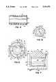
- FIG. 1is an exploded perspective view of a marine propeller according to the present invention
- FIG. 2is a side elevational view of the shaft sleeve of the propeller of FIG. 1;
- FIG. 3is a rear end elevational view of the shaft sleeve of FIG. 2;
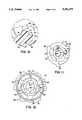
- FIG. 4is a center line, longitudinal cross-sectional view of the insert of the propeller of FIG. 1;
- FIG. 5is a rear elevational view of the insert of FIG. 4;
- FIG. 6is a fragmentary, front elevational view of the propeller hub of the propeller of FIG. 1;
- FIG. 7is a centerline, longitudinal cross-sectional view of the propeller hub of the propeller of FIG. 1;
- FIG. 8is a fragmentary cross-sectional view through the assembled propeller of FIG. 1;
- FIG. 9is the view of FIG. 8 under a high torque load condition showing distortion of the insert
- FIG. 10is an enlarged cross-sectional view of detail X of FIG. 3;
- FIG. 11is a schematic diagram of forces, shown on the view of FIG. 8.
- FIG. 12is the view of FIG. 6 showing an example of a modified cross-sectional shape for the insert and insert aperture.
- a screw type marine propelleris generally identified by the number 20 and has a hub assembly 22, an insert 24, and a shaft sleeve 26 (FIG. 1).
- Hub assembly 22includes an annular hub portion 28 with a generally cylindrical outer wall 30 (FIGS. 1, 6, and 7).
- a series of propeller blades 32extend radially outward from outer wall 30.
- the number and shape of blades 32may vary according to the specific propeller application. However, the number of blades 32 will typically be between two and four. Blades 32 will typically have some degree of skew and rake as is known in marine propellers. Blades 32 may also have a "cupped" trailing edge as is known in marine propellers.
- hub assembly 22including blades 32, may be made of any of the known materials for marine propellers, including, but not limited to, aluminum, bronze, and stainless steel for example
- hub assembly 22is preferably molded in a single piece of a fiber reinforced plastic material such as a 40% glass filled thermoplastic for example.
- a satisfactory thermoplastic material for this applicationis available under the trademark ISOPLAST from the Dow Chemical Company.
- propeller 20has a central axis of rotation 34 about which propeller 20 is designed to rotate in use.
- Annular hub 28has a length, extending along axis of rotation 34 and an inner wall 36 defining an aperture or cavity 38 which extends coaxially through at least a portion of the hub.
- Cavity 38has a generally polygonal cross-sectional shape and preferably a generally pentagonal cross-sectional shape with each vertex 40 of the pentagon being rounded.
- Cavity 38is slightly tapered from its widest point near a forward end 42 of propeller 20 to its narrowest point near a rear end 44 of propeller 20. This taper or draft facilitates the insertion into and removal from cavity 38 of insert 24 and the removal of hub assembly 22 from its manufacturing tooling. The preferred draft is about two degrees.
- a generally cylindrically shaped recess 46is provided at the forward end of cavity 38 for receiving a generally cylindrical flange portion 48 of shaft sleeve 26 (FIGS. 1-3 and 6-7).
- a cylindrical aperture 50is also provided at the rear end of cavity 38 and penetrates through the rear face 52 of hub assembly 22 from cavity 38 for receiving the rear portion 54 of shaft sleeve 26.
- a series of exhaust passages 56are formed through hub 28 for passage of exhaust fluids (FIGS. 1, 6, and 7).
- a series of spokes 58are defined between exhaust passages 56.
- the number of spokes 58corresponds to the number of exhaust passages 56 and is preferably related to the number of blades 32 so that each blade 32 may be centered over a spoke 58.
- exhaust passages 56are also preferably formed with some molding draft.
- Trailing edge portion 60is shown in FIG. 1 at rear end 44 of hub assembly 22. As with the design and shape of blades 32, the specific design of trailing edge portion 60 is variable and depends upon the requirements of the specific application. Trailing edge portion 60 may alternatively continue cylindrically straight rearward and have an outwardly tapering or conically shaped inner wall for example.
- Insert 24has a generally pentagonally shaped outer surface 62 corresponding to cavity 38 with rounded vertices 64 and is also preferably a single piece molding (FIGS. 1, 4, and 5). Insert 24 may be molded of any one of various resilient natural or synthetic materials which normally retain their molded shape, permit some flexing and distortion under shear, and resume their molded shape after the stress is removed. However, a preferred material for molding insert 24 is a urethane plastic having a 90-95 durometer specification. Insert 24 corresponds to cavity 38, has the same degree of draft as cavity 38, and is sized for slip fit engagement in an axial direction with cavity 38.
- Insert 24also has a generally cylindrical aperture 66 extending coaxially through insert 24 with a series of preferably five grooves or keyways 68 disposed circumferentially around aperture 66 for receiving shaft sleeve 26. Grooves 68 are also preferably equally spaced about the circumference of aperture 66 and aligned with vertices 64. Aperture 66 is formed with some degree of molding draft for ease of molding and assembly with shaft sleeve 26. The amount of draft molded into aperture 66 is preferably the same as for cavity 28 so that insert 24 has uniform thickness between outer surface 62 and aperture 66.
- shaft sleeve 26may be made of any of the known materials for marine propellers, including, but not limited to, aluminum, bronze, and stainless steel for example.
- Shaft sleeve 26is preferably a single piece molding of a fiber reinforced plastic material such as a 40% glass filled thermoplastic for example, as discussed above.
- Shaft sleeve 26is a generally cylindrical member, corresponding to aperture 66, with an outer wall 70 and a series of equally spaced teeth 72 disposed circumferentially thereabout (FIGS. 1-3). Shaft sleeve 26 is sized for hand forced slip fit engagement in an axial direction with aperture 66.
- Teeth 72extend linearly along the length of shaft sleeve 26 from a circumscribing flange portion 48 at its forward end to a point near, but spaced away from, the rear end of shaft sleeve 26, leaving a cylindrical portion 54 of shaft sleeve 26 which corresponds to aperture 50. However, depending upon the specific installation, teeth 72 may also extend curvilinearly along the length of shaft sleeve 26, defining a helical pattern (not shown). Each tooth 72 has a generally oval cross-sectional shape, specifically a U-shaped cross section with a pair of generally planar side walls 74 extending to and terminating at outer wall 70 from a semi-circular bight portion 76 (FIG. 10).
- Shaft sleeve 26also has a generally cylindrical mounting aperture 78 extending coaxially through sleeve 26.
- Mounting aperture 78is adapted for slip fit engagement with a propeller drive shaft.
- Mounting aperture 78may be formed with a series of splines 80 for mounting on a correspondingly splined propeller shaft.
- mounting aperture 78may take on configurations other than that shown in the figures as is appropriate for connection of propeller 20 with a specific propeller shaft.
- propeller 20is easily assembled by sliding shaft sleeve 26 into aperture 66 of insert 24, using hand force, and inserting the combination of shaft sleeve 26 and insert 24 into cavity 38 of hub assembly 22.
- hub assembly 22 and insert 24may be combined and shaft sleeve 26 then inserted into aperture 66 of insert 24, using hand force.
- shaft sleeve cylindrical portion 48nestles into hub cylindrical recess 46 and shaft sleeve rear portion 54 nestles into hub cylindrical aperture 50.
- This arrangementoffers a benefit of isolating insert 24 from the hostile environment in which a marine propeller is used. Specifically, exposure of insert 24 to exhaust fluids passing through hub assembly 22 is minimized.
- Assembled propeller 20is easily mounted on a propeller shaft by any of the various methods commonly known.
- insert 24will deform from its normal or molded pentagonal shape and allow relative rotational slippage between hub assembly 22 and shaft sleeve 26 (FIG. 9). Specifically, insert 24 will compress and flow into a space defined between adjoining pairs of teeth 72 and hub inner wall 36 while shaft sleeve 26 rotates relative to hub assembly 22 (FIG. 9). While some relative rotation between shaft sleeve 26 and insert 24 may also occur, this rotation is minor, if not insignificant.
- propeller 20After propeller 20 is subjected to a severe torque load as described above, propeller 20 retains its design torque load capacity even in the displaced condition described and shown in FIG. 9. Thus, propeller 20 provides significant residual torque load capacity after a severe torque incident so that the vessel is not stranded and may proceed normally. Further, the design torque load is maintained so that occurrence of a subsequent severe torque incident will not result in propulsion system damage by transferring excessive torque loading.
- propeller 20should also be inspected for damage after impacting an underwater obstacle or other severe torque load incident.
- Propeller 20is easily disassembled using standard shop tools to remove shaft sleeve 26 and insert 24 from cavity 38 and to remove insert 24 from shaft sleeve 26 (FIG. 1). After inspection and verification that hub assembly 22, insert 24, and shaft sleeve 26 are undamaged, propeller 20 may be easily reassembled and remounted as described above.
- the use of appropriate materials, whether metals or fiber reinforced plastics as discussed above, for hub assembly 22 and shaft sleeve 26enhances the damage-free use of propeller 20. Further as discussed above and further below, use of appropriate resilient, natural or synthetic materials for insert 24 also enhances the damage free use of propeller 20.
- the slippage behavior or propeller 20is in part attributable to the durometer specification of insert 24 and in part to the geometry of the interfaces between shaft sleeve 26 and insert 24 and between insert 24 and hub assembly 22. Insert materials possessing lower durometer specifications than the preferred range of 90-95 result in excessive slippage between shaft sleeve 26 and insert 24 so that maximum or design torque loading and transfer from the propeller shaft to blades 32 cannot reliably be obtained.
- the generally oval, specifically U-shaped, cross section of teeth 72transfers relatively high rotational forces from shaft sleeve 26 to insert 24 without a tendency for insert 24 to ramp over or lift away from shaft sleeve 26 and ride over the tops of teeth 72 (FIG. 10). Further, the preferred shape of teeth 72 avoids high stress concentrations in the vicinity of insert aperture 66. This characteristic of avoiding high stress concentrations minimizes any potential localized damage to insert 24 and any need to replace insert 24 because of such damage after severe torque loading of propeller 20.
Landscapes
- Chemical & Material Sciences (AREA)
- Engineering & Computer Science (AREA)
- Combustion & Propulsion (AREA)
- Mechanical Engineering (AREA)
- Ocean & Marine Engineering (AREA)
- Shafts, Cranks, Connecting Bars, And Related Bearings (AREA)
Abstract
Description
Claims (29)
Priority Applications (1)
| Application Number | Priority Date | Filing Date | Title |
|---|---|---|---|
| US07/806,653US5201679A (en) | 1991-12-13 | 1991-12-13 | Marine propeller with breakaway hub |
Applications Claiming Priority (1)
| Application Number | Priority Date | Filing Date | Title |
|---|---|---|---|
| US07/806,653US5201679A (en) | 1991-12-13 | 1991-12-13 | Marine propeller with breakaway hub |
Publications (1)
| Publication Number | Publication Date |
|---|---|
| US5201679Atrue US5201679A (en) | 1993-04-13 |
Family
ID=25194528
Family Applications (1)
| Application Number | Title | Priority Date | Filing Date |
|---|---|---|---|
| US07/806,653Expired - LifetimeUS5201679A (en) | 1991-12-13 | 1991-12-13 | Marine propeller with breakaway hub |
Country Status (1)
| Country | Link |
|---|---|
| US (1) | US5201679A (en) |
Cited By (129)
| Publication number | Priority date | Publication date | Assignee | Title |
|---|---|---|---|---|
| US5252028A (en)* | 1992-09-14 | 1993-10-12 | Lobosco Sam | Marine propeller assembly with shock absorbing hub and easily replaceable propeller housing |
| US5322416A (en)* | 1991-12-18 | 1994-06-21 | Brunswick Corporation | Torsionally twisting propeller drive sleeve |
| US5484264A (en)* | 1991-12-18 | 1996-01-16 | Brunswick Corporation | Torsionally twisting propeller drive sleeve and adapter |
| WO1996005101A1 (en)* | 1994-08-16 | 1996-02-22 | Spi (R & D) Pty. Ltd. | Mounting assembly for propellers |
| US5630704A (en)* | 1996-03-19 | 1997-05-20 | Brunswick Corporation | Propeller drive sleeve with asymmetric shock absorption |
| BE1011022A3 (en)* | 1997-01-29 | 1999-04-06 | Lin Yeun Junn | Propulsion propeller |
| US5897407A (en)* | 1996-05-24 | 1999-04-27 | Mendelson; Harold | Impeller |
| US5967751A (en)* | 1997-09-16 | 1999-10-19 | Chen; Fu Daul | Propeller assembly for marine engine |
| US6026536A (en)* | 1997-10-09 | 2000-02-22 | Lear Automotive Dearborn, Inc | Range limiting dual direction slip clutch |
| US6200098B1 (en) | 1999-07-01 | 2001-03-13 | Behr America, Inc. | Speed limited fan |
| US6383042B1 (en)* | 2000-04-11 | 2002-05-07 | Bombardier Motor Corporation Of America | Axial twist propeller hub |
| US6471481B2 (en) | 2001-01-02 | 2002-10-29 | Turning Point Propellers, Inc. | Hub assembly for marine propeller |
| US6478543B1 (en) | 2001-02-12 | 2002-11-12 | Brunswick Corporation | Torque transmitting device for mounting a propeller to a propeller shaft of a marine propulsion system |
| US6609892B1 (en)* | 2000-11-21 | 2003-08-26 | Bombardier Motor Corporation Of America | Propeller hub |
| US6672834B2 (en)* | 2001-12-21 | 2004-01-06 | Turning Point Propellers, Inc. | Removable propeller assembly incorporating breakaway elements |
| US20040091356A1 (en)* | 2001-11-13 | 2004-05-13 | Gerlach Charles L. | Labyrinth seal adapter for marine propeller |
| US6773232B2 (en) | 2001-07-30 | 2004-08-10 | Charles S. Powers | Progressive shear assembly for outboard motors and out drives |
| US6799946B1 (en)* | 2000-04-11 | 2004-10-05 | Bombardier Recreational Products Inc. | Propeller assembly |
| US20050186861A1 (en)* | 2004-02-20 | 2005-08-25 | Powers Charles S. | Exterior shear shoulder assembly for outboard motors and outdrives |
| WO2006002463A1 (en)* | 2004-06-30 | 2006-01-12 | Ringprop Trading Limited | Interchangeable propeller hub system |
| US20060010847A1 (en)* | 2004-07-01 | 2006-01-19 | George Vandyke | Blade slippage apparatus |
| US20060062672A1 (en)* | 2004-09-17 | 2006-03-23 | Mcbride Mark W | Expandable impeller pump |
| US20060263219A1 (en)* | 2005-05-19 | 2006-11-23 | Peter Dean | Boat propeller |
| US20070231135A1 (en)* | 2006-03-31 | 2007-10-04 | Orqis Medical Corporation | Rotary Blood Pump |
| US7350614B1 (en) | 2005-08-25 | 2008-04-01 | United States Of America As Represented By The Secretary Of The Army | System and method for vehicle cab with landmine protection |
| US20080089797A1 (en)* | 2003-09-18 | 2008-04-17 | Wampler Richard K | Rotary Blood Pump |
| US20080114339A1 (en)* | 2006-03-23 | 2008-05-15 | The Penn State Research Foundation | Heart assist device with expandable impeller pump |
| US20080139061A1 (en)* | 2006-11-14 | 2008-06-12 | Liheng Chen | Spindle with overmolded bushing |
| US20090129930A1 (en)* | 2005-05-24 | 2009-05-21 | Brunswick Corporation | Trolling motor propeller with elastomeric hub |
| US20090163089A1 (en)* | 2007-12-20 | 2009-06-25 | Liheng Chen | Propeller Assembly Incorporating Spindle With Fins And Overmolded Bushing |
| US20100016960A1 (en)* | 1997-10-09 | 2010-01-21 | Bolling Steven F | Implantable Heart Assist System And Method Of Applying Same |
| US20110004046A1 (en)* | 2009-07-01 | 2011-01-06 | The Penn State Research Foundation | Blood pump with expandable cannula |
| EP2031263A3 (en)* | 2007-08-30 | 2011-05-25 | Scambia Industrial Developments Aktiengesellschaft | Rotation connector unit |
| US8277269B1 (en) | 2010-07-09 | 2012-10-02 | Brunswick Corporation | Torque transmitting device and system for marine propulsion |
| US8485961B2 (en) | 2011-01-05 | 2013-07-16 | Thoratec Corporation | Impeller housing for percutaneous heart pump |
| US8591393B2 (en) | 2011-01-06 | 2013-11-26 | Thoratec Corporation | Catheter pump |
| US8597170B2 (en) | 2011-01-05 | 2013-12-03 | Thoratec Corporation | Catheter pump |
| US20130343816A1 (en)* | 2012-06-20 | 2013-12-26 | Goodrich Control Systems | Angular positioning arrangement |
| US8721517B2 (en) | 2012-05-14 | 2014-05-13 | Thoratec Corporation | Impeller for catheter pump |
| US20140205455A1 (en)* | 2013-01-22 | 2014-07-24 | Yamaha Hatsudoki Kabushiki Kaisha | Shock absorber for propeller unit, propeller unit, and vessel propulsion apparatus |
| US8821365B2 (en) | 2009-07-29 | 2014-09-02 | Thoratec Corporation | Rotation drive device and centrifugal pump apparatus using the same |
| US8827661B2 (en) | 2008-06-23 | 2014-09-09 | Thoratec Corporation | Blood pump apparatus |
| US20140339355A1 (en)* | 2013-05-15 | 2014-11-20 | Draganfly Innovations Inc. | Compact unmanned rotary aircraft |
| US8900060B2 (en) | 2009-04-29 | 2014-12-02 | Ecp Entwicklungsgesellschaft Mbh | Shaft arrangement having a shaft which extends within a fluid-filled casing |
| US8926492B2 (en) | 2011-10-11 | 2015-01-06 | Ecp Entwicklungsgesellschaft Mbh | Housing for a functional element |
| US8932141B2 (en) | 2009-10-23 | 2015-01-13 | Ecp Entwicklungsgesellschaft Mbh | Flexible shaft arrangement |
| US20150028531A1 (en)* | 2013-07-29 | 2015-01-29 | Benteler Automobiltechnik Gmbh | Elastomer bearing |
| US8944748B2 (en) | 2009-05-05 | 2015-02-03 | Ecp Entwicklungsgesellschaft Mbh | Fluid pump changeable in diameter, in particular for medical application |
| US8979493B2 (en) | 2009-03-18 | 2015-03-17 | ECP Entwicklungsgesellscaft mbH | Fluid pump |
| US8998792B2 (en) | 2008-12-05 | 2015-04-07 | Ecp Entwicklungsgesellschaft Mbh | Fluid pump with a rotor |
| US9028216B2 (en) | 2009-09-22 | 2015-05-12 | Ecp Entwicklungsgesellschaft Mbh | Rotor for an axial flow pump for conveying a fluid |
| US9067006B2 (en) | 2009-06-25 | 2015-06-30 | Ecp Entwicklungsgesellschaft Mbh | Compressible and expandable blade for a fluid pump |
| US9068572B2 (en) | 2010-07-12 | 2015-06-30 | Thoratec Corporation | Centrifugal pump apparatus |
| US9067005B2 (en) | 2008-12-08 | 2015-06-30 | Thoratec Corporation | Centrifugal pump apparatus |
| US9089670B2 (en) | 2009-02-04 | 2015-07-28 | Ecp Entwicklungsgesellschaft Mbh | Catheter device having a catheter and an actuation device |
| US9089634B2 (en) | 2009-09-22 | 2015-07-28 | Ecp Entwicklungsgesellschaft Mbh | Fluid pump having at least one impeller blade and a support device |
| US9133854B2 (en) | 2010-03-26 | 2015-09-15 | Thoratec Corporation | Centrifugal blood pump device |
| US9132215B2 (en) | 2010-02-16 | 2015-09-15 | Thoratee Corporation | Centrifugal pump apparatus |
| US9138518B2 (en) | 2011-01-06 | 2015-09-22 | Thoratec Corporation | Percutaneous heart pump |
| US9217442B2 (en) | 2010-03-05 | 2015-12-22 | Ecp Entwicklungsgesellschaft Mbh | Pump or rotary cutter for operation in a fluid |
| US9308302B2 (en) | 2013-03-15 | 2016-04-12 | Thoratec Corporation | Catheter pump assembly including a stator |
| US9314558B2 (en) | 2009-12-23 | 2016-04-19 | Ecp Entwicklungsgesellschaft Mbh | Conveying blades for a compressible rotor |
| US9328741B2 (en) | 2010-05-17 | 2016-05-03 | Ecp Entwicklungsgesellschaft Mbh | Pump arrangement |
| US9327067B2 (en) | 2012-05-14 | 2016-05-03 | Thoratec Corporation | Impeller for catheter pump |
| US9339596B2 (en) | 2009-12-23 | 2016-05-17 | Ecp Entwicklungsgesellschaft Mbh | Radially compressible and expandable rotor for a fluid pump |
| US9358330B2 (en) | 2009-12-23 | 2016-06-07 | Ecp Entwicklungsgesellschaft Mbh | Pump device having a detection device |
| US9358329B2 (en) | 2012-07-03 | 2016-06-07 | Thoratec Corporation | Catheter pump |
| US9366261B2 (en) | 2012-01-18 | 2016-06-14 | Thoratec Corporation | Centrifugal pump device |
| US9371826B2 (en) | 2013-01-24 | 2016-06-21 | Thoratec Corporation | Impeller position compensation using field oriented control |
| US9381285B2 (en) | 2009-03-05 | 2016-07-05 | Thoratec Corporation | Centrifugal pump apparatus |
| US9382908B2 (en) | 2010-09-14 | 2016-07-05 | Thoratec Corporation | Centrifugal pump apparatus |
| US9381288B2 (en) | 2013-03-13 | 2016-07-05 | Thoratec Corporation | Fluid handling system |
| US9410549B2 (en) | 2009-03-06 | 2016-08-09 | Thoratec Corporation | Centrifugal pump apparatus |
| US9416783B2 (en) | 2009-09-22 | 2016-08-16 | Ecp Entwicklungsgellschaft Mbh | Compressible rotor for a fluid pump |
| US9416791B2 (en) | 2010-01-25 | 2016-08-16 | Ecp Entwicklungsgesellschaft Mbh | Fluid pump having a radially compressible rotor |
| US9421311B2 (en) | 2012-07-03 | 2016-08-23 | Thoratec Corporation | Motor assembly for catheter pump |
| US9446179B2 (en) | 2012-05-14 | 2016-09-20 | Thoratec Corporation | Distal bearing support |
| US9556873B2 (en) | 2013-02-27 | 2017-01-31 | Tc1 Llc | Startup sequence for centrifugal pump with levitated impeller |
| US9603983B2 (en) | 2009-10-23 | 2017-03-28 | Ecp Entwicklungsgesellschaft Mbh | Catheter pump arrangement and flexible shaft arrangement having a core |
| US9611743B2 (en) | 2010-07-15 | 2017-04-04 | Ecp Entwicklungsgesellschaft Mbh | Radially compressible and expandable rotor for a pump having an impeller blade |
| US9623161B2 (en) | 2014-08-26 | 2017-04-18 | Tc1 Llc | Blood pump and method of suction detection |
| US9675739B2 (en) | 2015-01-22 | 2017-06-13 | Tc1 Llc | Motor assembly with heat exchanger for catheter pump |
| US9675738B2 (en) | 2015-01-22 | 2017-06-13 | Tc1 Llc | Attachment mechanisms for motor of catheter pump |
| US9713663B2 (en) | 2013-04-30 | 2017-07-25 | Tc1 Llc | Cardiac pump with speed adapted for ventricle unloading |
| US9771801B2 (en) | 2010-07-15 | 2017-09-26 | Ecp Entwicklungsgesellschaft Mbh | Rotor for a pump, produced with a first elastic material |
| US9770543B2 (en) | 2015-01-22 | 2017-09-26 | Tc1 Llc | Reduced rotational mass motor assembly for catheter pump |
| US9827356B2 (en) | 2014-04-15 | 2017-11-28 | Tc1 Llc | Catheter pump with access ports |
| US9850906B2 (en) | 2011-03-28 | 2017-12-26 | Tc1 Llc | Rotation drive device and centrifugal pump apparatus employing same |
| US9867916B2 (en) | 2010-08-27 | 2018-01-16 | Berlin Heart Gmbh | Implantable blood conveying device, manipulating device and coupling device |
| US9872947B2 (en) | 2012-05-14 | 2018-01-23 | Tc1 Llc | Sheath system for catheter pump |
| US9895475B2 (en) | 2010-07-15 | 2018-02-20 | Ecp Entwicklungsgesellschaft Mbh | Blood pump for the invasive application within a body of a patient |
| US9907890B2 (en) | 2015-04-16 | 2018-03-06 | Tc1 Llc | Catheter pump with positioning brace |
| US9974893B2 (en) | 2010-06-25 | 2018-05-22 | Ecp Entwicklungsgesellschaft Mbh | System for introducing a pump |
| US10029037B2 (en) | 2014-04-15 | 2018-07-24 | Tc1 Llc | Sensors for catheter pumps |
| US10052420B2 (en) | 2013-04-30 | 2018-08-21 | Tc1 Llc | Heart beat identification and pump speed synchronization |
| US10107299B2 (en) | 2009-09-22 | 2018-10-23 | Ecp Entwicklungsgesellschaft Mbh | Functional element, in particular fluid pump, having a housing and a conveying element |
| US10105475B2 (en) | 2014-04-15 | 2018-10-23 | Tc1 Llc | Catheter pump introducer systems and methods |
| US10117983B2 (en) | 2015-11-16 | 2018-11-06 | Tc1 Llc | Pressure/flow characteristic modification of a centrifugal pump in a ventricular assist device |
| US10166318B2 (en) | 2015-02-12 | 2019-01-01 | Tc1 Llc | System and method for controlling the position of a levitated rotor |
| US10172985B2 (en) | 2009-08-06 | 2019-01-08 | Ecp Entwicklungsgesellschaft Mbh | Catheter device having a coupling device for a drive device |
| US10245361B2 (en) | 2015-02-13 | 2019-04-02 | Tc1 Llc | Impeller suspension mechanism for heart pump |
| US10364010B2 (en) | 2016-05-23 | 2019-07-30 | Global Packaging Systems, LLC | Marine propulsion unit |
| US10371152B2 (en) | 2015-02-12 | 2019-08-06 | Tc1 Llc | Alternating pump gaps |
| US10391278B2 (en) | 2011-03-10 | 2019-08-27 | Ecp Entwicklungsgesellschaft Mbh | Push device for the axial insertion of an elongate, flexible body |
| US10506935B2 (en) | 2015-02-11 | 2019-12-17 | Tc1 Llc | Heart beat identification and pump speed synchronization |
| US10561773B2 (en) | 2011-09-05 | 2020-02-18 | Ecp Entwicklungsgesellschaft Mbh | Medical product comprising a functional element for the invasive use in a patient's body |
| US10583232B2 (en) | 2014-04-15 | 2020-03-10 | Tc1 Llc | Catheter pump with off-set motor position |
| USD894055S1 (en) | 2018-09-11 | 2020-08-25 | Brunswick Corporation | Shock absorbing hub assembly for supporting a propeller on a marine propulsion apparatus |
| US10759526B2 (en)* | 2016-11-18 | 2020-09-01 | Autel Robotics Co., Ltd. | Power assembly and aircraft |
| US20210131497A1 (en)* | 2018-02-22 | 2021-05-06 | Halliburton Energy Services, Inc. | Cylindrical Contact Polygon for Torque Transmission to a Driveshaft |
| US11077294B2 (en) | 2013-03-13 | 2021-08-03 | Tc1 Llc | Sheath assembly for catheter pump |
| US20210339855A1 (en)* | 2019-10-09 | 2021-11-04 | Kitty Hawk Corporation | Hybrid power systems for different modes of flight |
| US11219756B2 (en) | 2012-07-03 | 2022-01-11 | Tc1 Llc | Motor assembly for catheter pump |
| US20220021270A1 (en)* | 2020-07-20 | 2022-01-20 | Hyundai Mobis Co., Ltd. | Apparatus for power transmission of vehicle |
| US11229786B2 (en) | 2012-05-14 | 2022-01-25 | Tc1 Llc | Impeller for catheter pump |
| US11235138B2 (en) | 2015-09-25 | 2022-02-01 | Procyrion, Inc. | Non-occluding intravascular blood pump providing reduced hemolysis |
| US11241569B2 (en) | 2004-08-13 | 2022-02-08 | Procyrion, Inc. | Method and apparatus for long-term assisting a left ventricle to pump blood |
| US11267548B2 (en) | 2020-03-27 | 2022-03-08 | Rhodan Marine Systems Of Florida, Llc | Clutch mechanisms for steering control system |
| US11324940B2 (en) | 2019-12-03 | 2022-05-10 | Procyrion, Inc. | Blood pumps |
| US11351359B2 (en) | 2019-12-13 | 2022-06-07 | Procyrion, Inc. | Support structures for intravascular blood pumps |
| US11358697B1 (en) | 2020-01-08 | 2022-06-14 | Brunswick Corporation | Systems and methods for rotatably supporting counter-rotating propeller shafts in a marine propulsion device |
| US11364987B1 (en) | 2019-12-20 | 2022-06-21 | Brunswick Corporation | Systems and methods for absorbing shock with counter-rotating propeller shafts in a marine propulsion device |
| US11498506B2 (en)* | 2016-12-15 | 2022-11-15 | Trw Automotive Safety Systems Gmbh | Coupling device for mounting an airbag module to be oscillating on a vehicle steering wheel |
| US20230044002A1 (en)* | 2016-12-15 | 2023-02-09 | ZF Passive Safety Systems US Inc. | Coupling device for mounting an airbag module to be oscillating on a vehicle steering wheel |
| US11850414B2 (en) | 2013-03-13 | 2023-12-26 | Tc1 Llc | Fluid handling system |
| US20240075875A1 (en)* | 2022-09-05 | 2024-03-07 | Hyundai Motor Company | Steering wheel and damper unit thereof |
| US11999458B1 (en)* | 2022-07-14 | 2024-06-04 | Brunswick Corporation | Two-piece hub propeller assembly for marine drives |
| US20240239531A1 (en)* | 2022-08-09 | 2024-07-18 | Pete Bitar | Compact and Lightweight Drone Delivery Device called an ArcSpear Electric Jet Drone System Having an Electric Ducted Air Propulsion System and Being Relatively Difficult to Track in Flight |
| US12350483B2 (en) | 2016-07-21 | 2025-07-08 | Tc1 Llc | Fluid seals for catheter pump motor assembly |
Citations (39)
| Publication number | Priority date | Publication date | Assignee | Title |
|---|---|---|---|---|
| US390615A (en)* | 1888-10-02 | Chaeles g | ||
| US2070329A (en)* | 1934-09-29 | 1937-02-09 | Westinghouse Electric & Mfg Co | Flexible gear drive |
| GB558874A (en)* | 1942-10-14 | 1944-01-25 | Adrian Way Hope | Improvements in or relating to propellers |
| US2363469A (en)* | 1942-09-01 | 1944-11-21 | Metalastik Ltd | Flexible coupling, flexible mounting, and the like |
| US2539630A (en)* | 1946-01-12 | 1951-01-30 | West Bend Aluminum Co | Slip clutch |
| US2869774A (en)* | 1955-08-23 | 1959-01-20 | Reliance Electric & Eng Co | Removable hub |
| US2892329A (en)* | 1958-09-26 | 1959-06-30 | Gaetano T Trigilio | Drive mechanism |
| US2993544A (en)* | 1958-07-08 | 1961-07-25 | Mcculloch Corp | Propeller mounting for outboard motors |
| US3045763A (en)* | 1959-10-26 | 1962-07-24 | Perrott William | Shock absorbing positive drive means for marine propellers |
| US3064454A (en)* | 1961-06-06 | 1962-11-20 | Sharples Corp | Overload release coupling |
| US3096106A (en)* | 1960-09-15 | 1963-07-02 | Corduroy Rubber Company | Torque transmitting bearing |
| US3136370A (en)* | 1961-02-27 | 1964-06-09 | Minnesota Rubber Co | Outboard motor impeller hub |
| US3246698A (en)* | 1965-03-08 | 1966-04-19 | Kiekhaefer Corp | Diffuser-pump for marine propulsion propeller hub exhaust |
| US3256939A (en)* | 1965-01-11 | 1966-06-21 | Matthew J Novak | Marine propeller |
| US3307634A (en)* | 1966-01-17 | 1967-03-07 | Otto L Bihlmire | Hub construction for boat propellers |
| US3318388A (en)* | 1966-01-21 | 1967-05-09 | Otto L Bihlmire | Marine propeller |
| US3407882A (en)* | 1965-11-19 | 1968-10-29 | Brookside Corp | Resilient fan hub |
| US3477794A (en)* | 1967-02-14 | 1969-11-11 | Columbian Bronze Corp | Yielding bushing |
| US3563670A (en)* | 1969-01-31 | 1971-02-16 | Brunswick Corp | Marine propeller and its mounting |
| US3619882A (en)* | 1969-10-27 | 1971-11-16 | Chandler Evans Inc | Method of broaching a blank upon a shaft |
| US3701611A (en)* | 1970-12-21 | 1972-10-31 | Outboard Marine Corp | Marine propeller with resilient hub structure |
| US3748061A (en)* | 1971-12-13 | 1973-07-24 | Outboard Marine Corp | Propeller construction |
| US3764228A (en)* | 1971-10-04 | 1973-10-09 | F Shook | Replaceable blade propeller assembly |
| US3865509A (en)* | 1973-08-02 | 1975-02-11 | Brunswick Corp | Propeller construction |
| US3876331A (en)* | 1972-11-22 | 1975-04-08 | Robert Denherder | Removable propeller blade assembly |
| FR2360129A1 (en)* | 1976-07-30 | 1978-02-24 | Renault | WHEEL-TYPE SAFETY CONTROL BUTTON, ESPECIALLY FOR VEHICLE AIR CONDITIONING |
| US4338064A (en)* | 1980-03-31 | 1982-07-06 | Fred Carmel | Clutch assembly |
| US4414171A (en)* | 1982-01-28 | 1983-11-08 | The Boeing Co. | Method of making an injection molded propeller |
| US4417852A (en)* | 1981-08-28 | 1983-11-29 | Costabile John J | Marine propeller with replaceable blade sections |
| US4452591A (en)* | 1980-08-26 | 1984-06-05 | The Goodyear Tire & Rubber Company | Resilient rotary coupling |
| US4457735A (en)* | 1978-10-19 | 1984-07-03 | Koppers Company, Inc. | Gear type coupling with overload protection |
| US4477228A (en)* | 1982-01-28 | 1984-10-16 | The Boeing Company | Injection molded propeller |
| US4566855A (en)* | 1981-08-28 | 1986-01-28 | Costabile John J | Shock absorbing clutch assembly for marine propeller |
| US4575310A (en)* | 1983-03-17 | 1986-03-11 | Sanshin Kogyo Kabushiki Kaisha | Propeller shock absorber for marine propulsion device |
| US4626112A (en)* | 1984-01-27 | 1986-12-02 | The B.F. Goodrich Company | Propeller bearing |
| US4826404A (en)* | 1987-12-07 | 1989-05-02 | Zwicky Alan E | Marine propeller and hub assembly |
| US4842483A (en)* | 1986-07-07 | 1989-06-27 | Geary Edwin S | Propeller and coupling member |
| US4875829A (en)* | 1988-08-31 | 1989-10-24 | Van Der Woude Plastic Corporation | Marine propeller |
| US4930987A (en)* | 1989-05-24 | 1990-06-05 | Brad Stahl | Marine propeller and hub assembly of plastic |
- 1991
- 1991-12-13USUS07/806,653patent/US5201679A/ennot_activeExpired - Lifetime
Patent Citations (39)
| Publication number | Priority date | Publication date | Assignee | Title |
|---|---|---|---|---|
| US390615A (en)* | 1888-10-02 | Chaeles g | ||
| US2070329A (en)* | 1934-09-29 | 1937-02-09 | Westinghouse Electric & Mfg Co | Flexible gear drive |
| US2363469A (en)* | 1942-09-01 | 1944-11-21 | Metalastik Ltd | Flexible coupling, flexible mounting, and the like |
| GB558874A (en)* | 1942-10-14 | 1944-01-25 | Adrian Way Hope | Improvements in or relating to propellers |
| US2539630A (en)* | 1946-01-12 | 1951-01-30 | West Bend Aluminum Co | Slip clutch |
| US2869774A (en)* | 1955-08-23 | 1959-01-20 | Reliance Electric & Eng Co | Removable hub |
| US2993544A (en)* | 1958-07-08 | 1961-07-25 | Mcculloch Corp | Propeller mounting for outboard motors |
| US2892329A (en)* | 1958-09-26 | 1959-06-30 | Gaetano T Trigilio | Drive mechanism |
| US3045763A (en)* | 1959-10-26 | 1962-07-24 | Perrott William | Shock absorbing positive drive means for marine propellers |
| US3096106A (en)* | 1960-09-15 | 1963-07-02 | Corduroy Rubber Company | Torque transmitting bearing |
| US3136370A (en)* | 1961-02-27 | 1964-06-09 | Minnesota Rubber Co | Outboard motor impeller hub |
| US3064454A (en)* | 1961-06-06 | 1962-11-20 | Sharples Corp | Overload release coupling |
| US3256939A (en)* | 1965-01-11 | 1966-06-21 | Matthew J Novak | Marine propeller |
| US3246698A (en)* | 1965-03-08 | 1966-04-19 | Kiekhaefer Corp | Diffuser-pump for marine propulsion propeller hub exhaust |
| US3407882A (en)* | 1965-11-19 | 1968-10-29 | Brookside Corp | Resilient fan hub |
| US3307634A (en)* | 1966-01-17 | 1967-03-07 | Otto L Bihlmire | Hub construction for boat propellers |
| US3318388A (en)* | 1966-01-21 | 1967-05-09 | Otto L Bihlmire | Marine propeller |
| US3477794A (en)* | 1967-02-14 | 1969-11-11 | Columbian Bronze Corp | Yielding bushing |
| US3563670A (en)* | 1969-01-31 | 1971-02-16 | Brunswick Corp | Marine propeller and its mounting |
| US3619882A (en)* | 1969-10-27 | 1971-11-16 | Chandler Evans Inc | Method of broaching a blank upon a shaft |
| US3701611A (en)* | 1970-12-21 | 1972-10-31 | Outboard Marine Corp | Marine propeller with resilient hub structure |
| US3764228A (en)* | 1971-10-04 | 1973-10-09 | F Shook | Replaceable blade propeller assembly |
| US3748061A (en)* | 1971-12-13 | 1973-07-24 | Outboard Marine Corp | Propeller construction |
| US3876331A (en)* | 1972-11-22 | 1975-04-08 | Robert Denherder | Removable propeller blade assembly |
| US3865509A (en)* | 1973-08-02 | 1975-02-11 | Brunswick Corp | Propeller construction |
| FR2360129A1 (en)* | 1976-07-30 | 1978-02-24 | Renault | WHEEL-TYPE SAFETY CONTROL BUTTON, ESPECIALLY FOR VEHICLE AIR CONDITIONING |
| US4457735A (en)* | 1978-10-19 | 1984-07-03 | Koppers Company, Inc. | Gear type coupling with overload protection |
| US4338064A (en)* | 1980-03-31 | 1982-07-06 | Fred Carmel | Clutch assembly |
| US4452591A (en)* | 1980-08-26 | 1984-06-05 | The Goodyear Tire & Rubber Company | Resilient rotary coupling |
| US4417852A (en)* | 1981-08-28 | 1983-11-29 | Costabile John J | Marine propeller with replaceable blade sections |
| US4566855A (en)* | 1981-08-28 | 1986-01-28 | Costabile John J | Shock absorbing clutch assembly for marine propeller |
| US4414171A (en)* | 1982-01-28 | 1983-11-08 | The Boeing Co. | Method of making an injection molded propeller |
| US4477228A (en)* | 1982-01-28 | 1984-10-16 | The Boeing Company | Injection molded propeller |
| US4575310A (en)* | 1983-03-17 | 1986-03-11 | Sanshin Kogyo Kabushiki Kaisha | Propeller shock absorber for marine propulsion device |
| US4626112A (en)* | 1984-01-27 | 1986-12-02 | The B.F. Goodrich Company | Propeller bearing |
| US4842483A (en)* | 1986-07-07 | 1989-06-27 | Geary Edwin S | Propeller and coupling member |
| US4826404A (en)* | 1987-12-07 | 1989-05-02 | Zwicky Alan E | Marine propeller and hub assembly |
| US4875829A (en)* | 1988-08-31 | 1989-10-24 | Van Der Woude Plastic Corporation | Marine propeller |
| US4930987A (en)* | 1989-05-24 | 1990-06-05 | Brad Stahl | Marine propeller and hub assembly of plastic |
Cited By (312)
| Publication number | Priority date | Publication date | Assignee | Title |
|---|---|---|---|---|
| US5322416A (en)* | 1991-12-18 | 1994-06-21 | Brunswick Corporation | Torsionally twisting propeller drive sleeve |
| US5484264A (en)* | 1991-12-18 | 1996-01-16 | Brunswick Corporation | Torsionally twisting propeller drive sleeve and adapter |
| US5252028A (en)* | 1992-09-14 | 1993-10-12 | Lobosco Sam | Marine propeller assembly with shock absorbing hub and easily replaceable propeller housing |
| WO1996005101A1 (en)* | 1994-08-16 | 1996-02-22 | Spi (R & D) Pty. Ltd. | Mounting assembly for propellers |
| US5630704A (en)* | 1996-03-19 | 1997-05-20 | Brunswick Corporation | Propeller drive sleeve with asymmetric shock absorption |
| US5897407A (en)* | 1996-05-24 | 1999-04-27 | Mendelson; Harold | Impeller |
| BE1011022A3 (en)* | 1997-01-29 | 1999-04-06 | Lin Yeun Junn | Propulsion propeller |
| US5967751A (en)* | 1997-09-16 | 1999-10-19 | Chen; Fu Daul | Propeller assembly for marine engine |
| US6026536A (en)* | 1997-10-09 | 2000-02-22 | Lear Automotive Dearborn, Inc | Range limiting dual direction slip clutch |
| US20100016960A1 (en)* | 1997-10-09 | 2010-01-21 | Bolling Steven F | Implantable Heart Assist System And Method Of Applying Same |
| US7998054B2 (en) | 1997-10-09 | 2011-08-16 | Thoratec Corporation | Implantable heart assist system and method of applying same |
| US6200098B1 (en) | 1999-07-01 | 2001-03-13 | Behr America, Inc. | Speed limited fan |
| US6799946B1 (en)* | 2000-04-11 | 2004-10-05 | Bombardier Recreational Products Inc. | Propeller assembly |
| US6383042B1 (en)* | 2000-04-11 | 2002-05-07 | Bombardier Motor Corporation Of America | Axial twist propeller hub |
| US6609892B1 (en)* | 2000-11-21 | 2003-08-26 | Bombardier Motor Corporation Of America | Propeller hub |
| US6471481B2 (en) | 2001-01-02 | 2002-10-29 | Turning Point Propellers, Inc. | Hub assembly for marine propeller |
| EP1219534A3 (en)* | 2001-01-02 | 2004-01-07 | Turning Point Propellers, Inc. | Hub assembly for marine propeller |
| US6685432B2 (en) | 2001-01-02 | 2004-02-03 | Turning Point Propellers Inc. | Hub assembly for marine propeller |
| US6478543B1 (en) | 2001-02-12 | 2002-11-12 | Brunswick Corporation | Torque transmitting device for mounting a propeller to a propeller shaft of a marine propulsion system |
| US6773232B2 (en) | 2001-07-30 | 2004-08-10 | Charles S. Powers | Progressive shear assembly for outboard motors and out drives |
| US6835047B2 (en) | 2001-11-13 | 2004-12-28 | Michigan Wheel Corporation | Labyrinth seal adapter for marine propeller |
| US20040091356A1 (en)* | 2001-11-13 | 2004-05-13 | Gerlach Charles L. | Labyrinth seal adapter for marine propeller |
| US6672834B2 (en)* | 2001-12-21 | 2004-01-06 | Turning Point Propellers, Inc. | Removable propeller assembly incorporating breakaway elements |
| US8118724B2 (en) | 2003-09-18 | 2012-02-21 | Thoratec Corporation | Rotary blood pump |
| US20080089797A1 (en)* | 2003-09-18 | 2008-04-17 | Wampler Richard K | Rotary Blood Pump |
| US20080095648A1 (en)* | 2003-09-18 | 2008-04-24 | Wampler Richard K | Rotary Blood Pump |
| US20100135832A1 (en)* | 2003-09-18 | 2010-06-03 | Wampler Richard K | Rotary Blood Pump |
| US8684902B2 (en) | 2003-09-18 | 2014-04-01 | Thoratec Corporation | Rotary blood pump |
| US20050186861A1 (en)* | 2004-02-20 | 2005-08-25 | Powers Charles S. | Exterior shear shoulder assembly for outboard motors and outdrives |
| WO2006002463A1 (en)* | 2004-06-30 | 2006-01-12 | Ringprop Trading Limited | Interchangeable propeller hub system |
| US20060010847A1 (en)* | 2004-07-01 | 2006-01-19 | George Vandyke | Blade slippage apparatus |
| US7200982B2 (en) | 2004-07-01 | 2007-04-10 | Briggs & Stratton Corporation | Blade slippage apparatus |
| US11642511B2 (en) | 2004-08-13 | 2023-05-09 | Procyrion, Inc. | Method and apparatus for long-term assisting a left ventricle to pump blood |
| US11241569B2 (en) | 2004-08-13 | 2022-02-08 | Procyrion, Inc. | Method and apparatus for long-term assisting a left ventricle to pump blood |
| US9364593B2 (en) | 2004-09-17 | 2016-06-14 | The Penn State Research Foundation | Heart assist device with expandable impeller pump |
| US10215187B2 (en) | 2004-09-17 | 2019-02-26 | Tc1 Llc | Expandable impeller pump |
| US20090060743A1 (en)* | 2004-09-17 | 2009-03-05 | The Penn State Research Foundation | Expandable impeller pump |
| US8376707B2 (en) | 2004-09-17 | 2013-02-19 | Thoratec Corporation | Expandable impeller pump |
| US11428236B2 (en) | 2004-09-17 | 2022-08-30 | Tc1 Llc | Expandable impeller pump |
| US7393181B2 (en)* | 2004-09-17 | 2008-07-01 | The Penn State Research Foundation | Expandable impeller pump |
| US9364592B2 (en) | 2004-09-17 | 2016-06-14 | The Penn State Research Foundation | Heart assist device with expandable impeller pump |
| US20110236210A1 (en)* | 2004-09-17 | 2011-09-29 | The Penn State Research Foundation | Expandable impeller pump |
| US7927068B2 (en) | 2004-09-17 | 2011-04-19 | Thoratec Corporation | Expandable impeller pump |
| US20060062672A1 (en)* | 2004-09-17 | 2006-03-23 | Mcbride Mark W | Expandable impeller pump |
| US8992163B2 (en) | 2004-09-17 | 2015-03-31 | Thoratec Corporation | Expandable impeller pump |
| US9717833B2 (en) | 2004-09-17 | 2017-08-01 | The Penn State Research Foundation | Heart assist device with expandable impeller pump |
| US11434921B2 (en) | 2004-09-17 | 2022-09-06 | Tc1 Llc | Expandable impeller pump |
| US20060263219A1 (en)* | 2005-05-19 | 2006-11-23 | Peter Dean | Boat propeller |
| US7223073B2 (en) | 2005-05-19 | 2007-05-29 | Peter Dean | Boat propeller |
| US20090129930A1 (en)* | 2005-05-24 | 2009-05-21 | Brunswick Corporation | Trolling motor propeller with elastomeric hub |
| US7350614B1 (en) | 2005-08-25 | 2008-04-01 | United States Of America As Represented By The Secretary Of The Army | System and method for vehicle cab with landmine protection |
| US20080114339A1 (en)* | 2006-03-23 | 2008-05-15 | The Penn State Research Foundation | Heart assist device with expandable impeller pump |
| US12404858B2 (en) | 2006-03-23 | 2025-09-02 | The Penn State Research Foundation | Catheter blood pump heart assist device |
| US10149932B2 (en) | 2006-03-23 | 2018-12-11 | The Penn State Research Foundation | Heart assist device with expandable impeller pump |
| US10864309B2 (en) | 2006-03-23 | 2020-12-15 | The Penn State Research Foundation | Heart assist device with expandable impeller pump |
| US11708833B2 (en) | 2006-03-23 | 2023-07-25 | The Penn State Research Foundation | Heart assist device with expandable impeller pump |
| US7841976B2 (en) | 2006-03-23 | 2010-11-30 | Thoratec Corporation | Heart assist device with expandable impeller pump |
| US9512852B2 (en) | 2006-03-31 | 2016-12-06 | Thoratec Corporation | Rotary blood pump |
| US20070231135A1 (en)* | 2006-03-31 | 2007-10-04 | Orqis Medical Corporation | Rotary Blood Pump |
| EP2081819A4 (en)* | 2006-11-14 | 2012-10-24 | Turning Point Propellers Inc | Spindle with overmolded bushing |
| US20080139061A1 (en)* | 2006-11-14 | 2008-06-12 | Liheng Chen | Spindle with overmolded bushing |
| US7717678B2 (en) | 2006-11-14 | 2010-05-18 | Turning Point Propellers, Inc. | Spindle with overmolded bushing |
| WO2008073590A3 (en)* | 2006-11-14 | 2008-07-31 | Turning Point Propellers Inc | Spindle with overmolded bushing |
| EP2031263A3 (en)* | 2007-08-30 | 2011-05-25 | Scambia Industrial Developments Aktiengesellschaft | Rotation connector unit |
| US20090163089A1 (en)* | 2007-12-20 | 2009-06-25 | Liheng Chen | Propeller Assembly Incorporating Spindle With Fins And Overmolded Bushing |
| US7708526B2 (en) | 2007-12-20 | 2010-05-04 | Turning Point Propellers, Inc. | Propeller assembly incorporating spindle with fins and overmolded bushing |
| US9109601B2 (en) | 2008-06-23 | 2015-08-18 | Thoratec Corporation | Blood pump apparatus |
| US8827661B2 (en) | 2008-06-23 | 2014-09-09 | Thoratec Corporation | Blood pump apparatus |
| US10662967B2 (en) | 2008-12-05 | 2020-05-26 | Ecp Entwicklungsgesellschaft Mbh | Fluid pump with a rotor |
| US9964115B2 (en) | 2008-12-05 | 2018-05-08 | Ecp Entwicklungsgesellschaft Mbh | Fluid pump with a rotor |
| US12209593B2 (en) | 2008-12-05 | 2025-01-28 | Ecp Entwicklungsgesellschaft Mbh | Fluid pump with a rotor |
| US8998792B2 (en) | 2008-12-05 | 2015-04-07 | Ecp Entwicklungsgesellschaft Mbh | Fluid pump with a rotor |
| US9404505B2 (en) | 2008-12-05 | 2016-08-02 | Ecp Entwicklungsgesellschaft Mbh | Fluid pump with a rotor |
| US11852155B2 (en) | 2008-12-05 | 2023-12-26 | Ecp Entwicklungsgesellschaft Mbh | Fluid pump with a rotor |
| US10495101B2 (en) | 2008-12-05 | 2019-12-03 | Ecp Entwicklungsgesellschaft Mbh | Fluid pump with a rotor |
| US9067005B2 (en) | 2008-12-08 | 2015-06-30 | Thoratec Corporation | Centrifugal pump apparatus |
| US11229774B2 (en) | 2009-02-04 | 2022-01-25 | Ecp Entwicklungsgesellschaft Mbh | Catheter device having a catheter and an actuation device |
| US11969560B2 (en) | 2009-02-04 | 2024-04-30 | Ecp Entwicklungsgesellschaft Mbh | Catheter device having a catheter and an actuation device |
| US9089670B2 (en) | 2009-02-04 | 2015-07-28 | Ecp Entwicklungsgesellschaft Mbh | Catheter device having a catheter and an actuation device |
| US9649475B2 (en) | 2009-02-04 | 2017-05-16 | Ecp Entwicklungsgesellschaft Mbh | Catheter device having a catheter and an actuation device |
| US12377246B2 (en) | 2009-02-04 | 2025-08-05 | Ecp Entwicklungsgesellschaft Mbh | Catheter device having a catheter and an actuation device |
| US10406323B2 (en) | 2009-02-04 | 2019-09-10 | Ecp Entwicklungsgesellschaft Mbh | Catheter device having a catheter and an actuation device |
| US9981110B2 (en) | 2009-02-04 | 2018-05-29 | Ecp Entwicklungsgesellschaft Mbh | Catheter device having a catheter and an actuation device |
| US9381285B2 (en) | 2009-03-05 | 2016-07-05 | Thoratec Corporation | Centrifugal pump apparatus |
| US9410549B2 (en) | 2009-03-06 | 2016-08-09 | Thoratec Corporation | Centrifugal pump apparatus |
| US8979493B2 (en) | 2009-03-18 | 2015-03-17 | ECP Entwicklungsgesellscaft mbH | Fluid pump |
| US8900060B2 (en) | 2009-04-29 | 2014-12-02 | Ecp Entwicklungsgesellschaft Mbh | Shaft arrangement having a shaft which extends within a fluid-filled casing |
| US11577066B2 (en) | 2009-05-05 | 2023-02-14 | Ecp Entwicklundgesellschaft Mbh | Fluid pump changeable in diameter, in particular for medical application |
| US11786718B2 (en) | 2009-05-05 | 2023-10-17 | Ecp Entwicklungsgesellschaft Mbh | Fluid pump changeable in diameter, in particular for medical application |
| US10265448B2 (en) | 2009-05-05 | 2019-04-23 | Ecp Entwicklungsgesellschaft Mbh | Fluid pump changeable in diameter, in particular for medical application |
| US11278711B2 (en) | 2009-05-05 | 2022-03-22 | Ecp Entwicklungsgesellschaft Mbh | Fluid pump changeable in diameter, in particular for medical application |
| US8944748B2 (en) | 2009-05-05 | 2015-02-03 | Ecp Entwicklungsgesellschaft Mbh | Fluid pump changeable in diameter, in particular for medical application |
| US9512839B2 (en) | 2009-05-05 | 2016-12-06 | Ecp Entwicklungsgesellschaft Mbh | Fluid pump changeable in diameter, in particular for medical application |
| US9067006B2 (en) | 2009-06-25 | 2015-06-30 | Ecp Entwicklungsgesellschaft Mbh | Compressible and expandable blade for a fluid pump |
| US11268521B2 (en) | 2009-06-25 | 2022-03-08 | Ecp Entwicklungsgesellschaft Mbh | Compressible and expandable blade for a fluid pump |
| US12372092B2 (en) | 2009-06-25 | 2025-07-29 | Ecp Entwicklungsgesellschaft Mbh | Compressible and expandable blade for a fluid pump |
| US10330101B2 (en) | 2009-06-25 | 2019-06-25 | Ecp Entwicklungsgesellschaft Mbh | Compressible and expandable blade for a fluid pump |
| US11994133B2 (en) | 2009-06-25 | 2024-05-28 | Ecp Entwicklungsgesellschaft Mbh | Compressible and expandable blade for a fluid pump |
| US8535211B2 (en) | 2009-07-01 | 2013-09-17 | Thoratec Corporation | Blood pump with expandable cannula |
| US20110004046A1 (en)* | 2009-07-01 | 2011-01-06 | The Penn State Research Foundation | Blood pump with expandable cannula |
| US8684904B2 (en) | 2009-07-01 | 2014-04-01 | Thoratec Corporation | Blood pump with expandable cannula |
| US8821365B2 (en) | 2009-07-29 | 2014-09-02 | Thoratec Corporation | Rotation drive device and centrifugal pump apparatus using the same |
| US12042647B2 (en) | 2009-08-06 | 2024-07-23 | Ecp Entwicklungsgesellschaft Mbh | Catheter device having a coupling device for a drive device |
| US11116960B2 (en) | 2009-08-06 | 2021-09-14 | Ecp Entwicklungsgesellschaft Mbh | Catheter device having a coupling device for a drive device |
| US10172985B2 (en) | 2009-08-06 | 2019-01-08 | Ecp Entwicklungsgesellschaft Mbh | Catheter device having a coupling device for a drive device |
| US11592028B2 (en) | 2009-09-22 | 2023-02-28 | Ecp Entwicklungsgesellschaft Mbh | Fluid pump having at least one impeller blade and a support device |
| US9089634B2 (en) | 2009-09-22 | 2015-07-28 | Ecp Entwicklungsgesellschaft Mbh | Fluid pump having at least one impeller blade and a support device |
| US10107299B2 (en) | 2009-09-22 | 2018-10-23 | Ecp Entwicklungsgesellschaft Mbh | Functional element, in particular fluid pump, having a housing and a conveying element |
| US10208763B2 (en) | 2009-09-22 | 2019-02-19 | Ecp Entwicklungsgesellschaft Mbh | Fluid pump having at least one impeller blade and a support device |
| US12066030B2 (en) | 2009-09-22 | 2024-08-20 | Ecp Entwicklungsgesellschaft Mbh | Fluid pump having at least one impeller blade and a support device |
| US11773861B2 (en) | 2009-09-22 | 2023-10-03 | Ecp Entwicklungsgesellschaft Mbh | Compressible rotor for a fluid pump |
| US9416783B2 (en) | 2009-09-22 | 2016-08-16 | Ecp Entwicklungsgellschaft Mbh | Compressible rotor for a fluid pump |
| US12276285B2 (en) | 2009-09-22 | 2025-04-15 | Ecp Entwicklungsgesellschaft Mbh | Compressible rotor for a fluid pump |
| US9028216B2 (en) | 2009-09-22 | 2015-05-12 | Ecp Entwicklungsgesellschaft Mbh | Rotor for an axial flow pump for conveying a fluid |
| US11421701B2 (en) | 2009-09-22 | 2022-08-23 | Ecp Entwicklungsgesellschaft Mbh | Compressible rotor for a fluid pump |
| US10792406B2 (en) | 2009-10-23 | 2020-10-06 | Ecp Entwicklungsgesellschaft Mbh | Catheter pump arrangement and flexible shaft arrangement having a core |
| US12313113B2 (en) | 2009-10-23 | 2025-05-27 | Ecp Entwicklungsgesellschaft Mbh | Catheter pump arrangement and flexible shaft arrangement having a core |
| US9603983B2 (en) | 2009-10-23 | 2017-03-28 | Ecp Entwicklungsgesellschaft Mbh | Catheter pump arrangement and flexible shaft arrangement having a core |
| US8932141B2 (en) | 2009-10-23 | 2015-01-13 | Ecp Entwicklungsgesellschaft Mbh | Flexible shaft arrangement |
| US9339596B2 (en) | 2009-12-23 | 2016-05-17 | Ecp Entwicklungsgesellschaft Mbh | Radially compressible and expandable rotor for a fluid pump |
| US9314558B2 (en) | 2009-12-23 | 2016-04-19 | Ecp Entwicklungsgesellschaft Mbh | Conveying blades for a compressible rotor |
| US9358330B2 (en) | 2009-12-23 | 2016-06-07 | Ecp Entwicklungsgesellschaft Mbh | Pump device having a detection device |
| US11549517B2 (en) | 2009-12-23 | 2023-01-10 | Ecp Entwicklungsgesellschaft Mbh | Conveying blades for a compressible rotor |
| US9795727B2 (en) | 2009-12-23 | 2017-10-24 | Ecp Entwicklungsgesellschaft Mbh | Pump device having a detection device |
| US11266824B2 (en) | 2009-12-23 | 2022-03-08 | Ecp Entwicklungsgesellschaft Mbh | Conveying blades for a compressible rotor |
| US12305662B2 (en) | 2009-12-23 | 2025-05-20 | Ecp Entwicklungsgesellschaft Mbh | Conveying blades for a compressible rotor |
| US10806838B2 (en) | 2009-12-23 | 2020-10-20 | Ecp Entwicklungsgesellschaft Mbh | Conveying blades for a compressible rotor |
| US12085088B2 (en) | 2009-12-23 | 2024-09-10 | Ecp Entwicklungsgesellschaft Mbh | Radially compressible and expandable rotor for a fluid pump |
| US11815097B2 (en) | 2009-12-23 | 2023-11-14 | Ecp Entwicklungsgesellschaft Mbh | Pump device having a detection device |
| US11781557B2 (en) | 2009-12-23 | 2023-10-10 | Ecp Entwicklungsgesellschaft Mbh | Radially compressible and expandable rotor for a fluid pump |
| US9903384B2 (en) | 2009-12-23 | 2018-02-27 | Ecp Entwicklungsgesellschaft Mbh | Radially compressible and expandable rotor for a fluid pump |
| US10557475B2 (en) | 2009-12-23 | 2020-02-11 | Ecp Entwicklungsgesellschaft Mbh | Radially compressible and expandable rotor for a fluid pump |
| US11773863B2 (en) | 2009-12-23 | 2023-10-03 | Ecp Entwicklungsgesellschaft Mbh | Conveying blades for a compressible rotor |
| US12158151B2 (en) | 2009-12-23 | 2024-12-03 | Ecp Entwicklungsgesellschaft Mbh | Pump device having a detection device |
| US10561772B2 (en) | 2009-12-23 | 2020-02-18 | Ecp Entwicklungsgesellschaft Mbh | Pump device having a detection device |
| US11434922B2 (en) | 2009-12-23 | 2022-09-06 | Ecp Entwicklungsgesellschaft Mbh | Radially compressible and expandable rotor for a fluid pump |
| US11486400B2 (en) | 2009-12-23 | 2022-11-01 | Ecp Entwicklungsgesellschaft Mbh | Pump device having a detection device |
| US12117014B2 (en) | 2009-12-23 | 2024-10-15 | Ecp Entwicklungsgesellschaft Mbh | Conveying blades for a compressible rotor |
| US12018698B2 (en) | 2010-01-25 | 2024-06-25 | Ecp Entwicklungsgesellschaft Mbh | Fluid pump having a radially compressible rotor |
| US10316853B2 (en) | 2010-01-25 | 2019-06-11 | Ecp Entwicklungsgesellschaft Mbh | Fluid pump having a radially compressible rotor |
| US11517739B2 (en) | 2010-01-25 | 2022-12-06 | Ecp Entwicklungsgesellschaft Mbh | Fluid pump having a radially compressible rotor |
| US9416791B2 (en) | 2010-01-25 | 2016-08-16 | Ecp Entwicklungsgesellschaft Mbh | Fluid pump having a radially compressible rotor |
| US9132215B2 (en) | 2010-02-16 | 2015-09-15 | Thoratee Corporation | Centrifugal pump apparatus |
| US9217442B2 (en) | 2010-03-05 | 2015-12-22 | Ecp Entwicklungsgesellschaft Mbh | Pump or rotary cutter for operation in a fluid |
| US11986205B2 (en) | 2010-03-05 | 2024-05-21 | Ecp Entwicklungsgesellschaft Mbh | Pump or rotary cutter for operation in a fluid |
| US10413646B2 (en) | 2010-03-05 | 2019-09-17 | Ecp Entwicklungsgesellschaft Mbh | Pump or rotary cutter for operation in a fluid |
| US9907891B2 (en) | 2010-03-05 | 2018-03-06 | Ecp Entwicklungsgesellschaft Mbh | Pump or rotary cutter for operation in a fluid |
| US9133854B2 (en) | 2010-03-26 | 2015-09-15 | Thoratec Corporation | Centrifugal blood pump device |
| US11168705B2 (en) | 2010-05-17 | 2021-11-09 | Ecp Entwicklungsgesellschaft Mbh | Pump arrangement |
| US11976674B2 (en) | 2010-05-17 | 2024-05-07 | Ecp Entwicklungsgesellschaft Mbh | Pump arrangement |
| US9759237B2 (en) | 2010-05-17 | 2017-09-12 | Ecp Entwicklungsgesellschaft Mbh | Pump arrangement |
| US9328741B2 (en) | 2010-05-17 | 2016-05-03 | Ecp Entwicklungsgesellschaft Mbh | Pump arrangement |
| US10221866B2 (en) | 2010-05-17 | 2019-03-05 | Ecp Entwicklungsgesellschaft Mbh | Pump arrangement |
| US9974893B2 (en) | 2010-06-25 | 2018-05-22 | Ecp Entwicklungsgesellschaft Mbh | System for introducing a pump |
| US11957846B2 (en) | 2010-06-25 | 2024-04-16 | Ecp Entwicklungsgesellschaft Mbh | System for introducing a pump |
| US10898625B2 (en) | 2010-06-25 | 2021-01-26 | Ecp Entwicklungsgesellschaft Mbh | System for introducing a pump |
| US10874781B2 (en) | 2010-06-25 | 2020-12-29 | Ecp Entwicklungsgesellschaft Mbh | System for introducing a pump |
| US8277269B1 (en) | 2010-07-09 | 2012-10-02 | Brunswick Corporation | Torque transmitting device and system for marine propulsion |
| US9068572B2 (en) | 2010-07-12 | 2015-06-30 | Thoratec Corporation | Centrifugal pump apparatus |
| US11702938B2 (en) | 2010-07-15 | 2023-07-18 | Ecp Entwicklungsgesellschaft Mbh | Rotor for a pump, produced with a first elastic material |
| US11913467B2 (en) | 2010-07-15 | 2024-02-27 | Ecp Entwicklungsgesellschaft Mbh | Radially compressible and expandable rotor for a pump having an impeller blade |
| US9771801B2 (en) | 2010-07-15 | 2017-09-26 | Ecp Entwicklungsgesellschaft Mbh | Rotor for a pump, produced with a first elastic material |
| US10920596B2 (en) | 2010-07-15 | 2021-02-16 | Ecp Entwicklungsgesellschaft Mbh | Radially compressible and expandable rotor for a pump having an impeller blade |
| US12065941B2 (en) | 2010-07-15 | 2024-08-20 | Ecp Entwicklungsgesellschaft Mbh | Rotor for a pump, produced with a first elastic material |
| US11844939B2 (en) | 2010-07-15 | 2023-12-19 | Ecp Entwicklungsgesellschaft Mbh | Blood pump for the invasive application within a body of a patient |
| US9895475B2 (en) | 2010-07-15 | 2018-02-20 | Ecp Entwicklungsgesellschaft Mbh | Blood pump for the invasive application within a body of a patient |
| US9611743B2 (en) | 2010-07-15 | 2017-04-04 | Ecp Entwicklungsgesellschaft Mbh | Radially compressible and expandable rotor for a pump having an impeller blade |
| US10584589B2 (en) | 2010-07-15 | 2020-03-10 | Ecp Entwicklungsgellschaft Mbh | Rotor for a pump having helical expandable blades |
| US10589012B2 (en) | 2010-07-15 | 2020-03-17 | Ecp Entwicklungsgesellschaft Mbh | Blood pump for the invasive application within a body of a patient |
| US9867916B2 (en) | 2010-08-27 | 2018-01-16 | Berlin Heart Gmbh | Implantable blood conveying device, manipulating device and coupling device |
| US11083885B2 (en) | 2010-08-27 | 2021-08-10 | Berlin Heart Gmbh | Implantable blood conveying device, manipulating device and coupling device |
| US9382908B2 (en) | 2010-09-14 | 2016-07-05 | Thoratec Corporation | Centrifugal pump apparatus |
| US9638202B2 (en) | 2010-09-14 | 2017-05-02 | Tc1 Llc | Centrifugal pump apparatus |
| US8485961B2 (en) | 2011-01-05 | 2013-07-16 | Thoratec Corporation | Impeller housing for percutaneous heart pump |
| US8597170B2 (en) | 2011-01-05 | 2013-12-03 | Thoratec Corporation | Catheter pump |
| US9138518B2 (en) | 2011-01-06 | 2015-09-22 | Thoratec Corporation | Percutaneous heart pump |
| US9962475B2 (en) | 2011-01-06 | 2018-05-08 | Tc1 Llc | Percutaneous heart pump |
| US8591393B2 (en) | 2011-01-06 | 2013-11-26 | Thoratec Corporation | Catheter pump |
| US11235125B2 (en) | 2011-03-10 | 2022-02-01 | Ecp Entwicklungsgesellschaft Mbh | Push device for the axial insertion of an elongate, flexible body |
| US10391278B2 (en) | 2011-03-10 | 2019-08-27 | Ecp Entwicklungsgesellschaft Mbh | Push device for the axial insertion of an elongate, flexible body |
| US9850906B2 (en) | 2011-03-28 | 2017-12-26 | Tc1 Llc | Rotation drive device and centrifugal pump apparatus employing same |
| US10561773B2 (en) | 2011-09-05 | 2020-02-18 | Ecp Entwicklungsgesellschaft Mbh | Medical product comprising a functional element for the invasive use in a patient's body |
| US11666746B2 (en) | 2011-09-05 | 2023-06-06 | Ecp Entwicklungsgesellschaft Mbh | Medical product comprising a functional element for the invasive use in a patient's body |
| US8926492B2 (en) | 2011-10-11 | 2015-01-06 | Ecp Entwicklungsgesellschaft Mbh | Housing for a functional element |
| US9366261B2 (en) | 2012-01-18 | 2016-06-14 | Thoratec Corporation | Centrifugal pump device |
| US10039872B2 (en) | 2012-05-14 | 2018-08-07 | Tc1 Llc | Impeller for catheter pump |
| US10765789B2 (en) | 2012-05-14 | 2020-09-08 | Tc1 Llc | Impeller for catheter pump |
| US9446179B2 (en) | 2012-05-14 | 2016-09-20 | Thoratec Corporation | Distal bearing support |
| US9327067B2 (en) | 2012-05-14 | 2016-05-03 | Thoratec Corporation | Impeller for catheter pump |
| US9675740B2 (en) | 2012-05-14 | 2017-06-13 | Tc1 Llc | Impeller for catheter pump |
| US11357967B2 (en) | 2012-05-14 | 2022-06-14 | Tc1 Llc | Impeller for catheter pump |
| US11260213B2 (en) | 2012-05-14 | 2022-03-01 | Tc1 Llc | Impeller for catheter pump |
| US9872947B2 (en) | 2012-05-14 | 2018-01-23 | Tc1 Llc | Sheath system for catheter pump |
| US11229786B2 (en) | 2012-05-14 | 2022-01-25 | Tc1 Llc | Impeller for catheter pump |
| US11311712B2 (en) | 2012-05-14 | 2022-04-26 | Tc1 Llc | Impeller for catheter pump |
| US10117980B2 (en) | 2012-05-14 | 2018-11-06 | Tc1 Llc | Distal bearing support |
| US8721517B2 (en) | 2012-05-14 | 2014-05-13 | Thoratec Corporation | Impeller for catheter pump |
| US9279458B2 (en)* | 2012-06-20 | 2016-03-08 | Goodrich Control Systems | Angular positioning arrangement |
| US20130343816A1 (en)* | 2012-06-20 | 2013-12-26 | Goodrich Control Systems | Angular positioning arrangement |
| US11944802B2 (en) | 2012-07-03 | 2024-04-02 | Tc1 Llc | Motor assembly for catheter pump |
| US12337165B2 (en) | 2012-07-03 | 2025-06-24 | Tc1 Llc | Catheter pump |
| US11219756B2 (en) | 2012-07-03 | 2022-01-11 | Tc1 Llc | Motor assembly for catheter pump |
| US9421311B2 (en) | 2012-07-03 | 2016-08-23 | Thoratec Corporation | Motor assembly for catheter pump |
| US10576193B2 (en) | 2012-07-03 | 2020-03-03 | Tc1 Llc | Motor assembly for catheter pump |
| US11833342B2 (en) | 2012-07-03 | 2023-12-05 | Tc1 Llc | Motor assembly for catheter pump |
| US9358329B2 (en) | 2012-07-03 | 2016-06-07 | Thoratec Corporation | Catheter pump |
| US10086121B2 (en) | 2012-07-03 | 2018-10-02 | Tc1 Llc | Catheter pump |
| US11654276B2 (en) | 2012-07-03 | 2023-05-23 | Tc1 Llc | Catheter pump |
| US11660441B2 (en) | 2012-07-03 | 2023-05-30 | Tc1 Llc | Catheter pump |
| US11925796B2 (en) | 2012-07-03 | 2024-03-12 | Tc1 Llc | Motor assembly for catheter pump |
| US12102813B2 (en) | 2012-07-03 | 2024-10-01 | Tc1 Llc | Motor assembly for catheter pump |
| US11058865B2 (en) | 2012-07-03 | 2021-07-13 | Tc1 Llc | Catheter pump |
| US11944801B2 (en) | 2012-07-03 | 2024-04-02 | Tc1 Llc | Motor assembly for catheter pump |
| US11925797B2 (en) | 2012-07-03 | 2024-03-12 | Tc1 Llc | Motor assembly for catheter pump |
| US20140205455A1 (en)* | 2013-01-22 | 2014-07-24 | Yamaha Hatsudoki Kabushiki Kaisha | Shock absorber for propeller unit, propeller unit, and vessel propulsion apparatus |
| US9840314B2 (en)* | 2013-01-22 | 2017-12-12 | Yamaha Hatsudoki Kabushiki Kaisha | Shock absorber for propeller unit, propeller unit, and vessel propulsion apparatus |
| US9709061B2 (en) | 2013-01-24 | 2017-07-18 | Tc1 Llc | Impeller position compensation using field oriented control |
| US9371826B2 (en) | 2013-01-24 | 2016-06-21 | Thoratec Corporation | Impeller position compensation using field oriented control |
| US9556873B2 (en) | 2013-02-27 | 2017-01-31 | Tc1 Llc | Startup sequence for centrifugal pump with levitated impeller |
| US11077294B2 (en) | 2013-03-13 | 2021-08-03 | Tc1 Llc | Sheath assembly for catheter pump |
| US11964119B2 (en) | 2013-03-13 | 2024-04-23 | Tc1 Llc | Sheath assembly for catheter pump |
| US11850414B2 (en) | 2013-03-13 | 2023-12-26 | Tc1 Llc | Fluid handling system |
| US11547845B2 (en) | 2013-03-13 | 2023-01-10 | Tc1 Llc | Fluid handling system |
| US10632241B2 (en) | 2013-03-13 | 2020-04-28 | Tc1 Llc | Fluid handling system |
| US9381288B2 (en) | 2013-03-13 | 2016-07-05 | Thoratec Corporation | Fluid handling system |
| US9308302B2 (en) | 2013-03-15 | 2016-04-12 | Thoratec Corporation | Catheter pump assembly including a stator |
| US10456513B2 (en) | 2013-04-30 | 2019-10-29 | Tc1 Llc | Cardiac pump with speed adapted for ventricle unloading |
| US12343517B2 (en) | 2013-04-30 | 2025-07-01 | Tc1 Llc | Cardiac pump with speed adapted for ventricle unloading |
| US11724094B2 (en) | 2013-04-30 | 2023-08-15 | Tc1 Llc | Cardiac pump with speed adapted for ventricle unloading |
| US10980928B2 (en) | 2013-04-30 | 2021-04-20 | Tc1 Llc | Cardiac pump with speed adapted for ventricle unloading |
| US9713663B2 (en) | 2013-04-30 | 2017-07-25 | Tc1 Llc | Cardiac pump with speed adapted for ventricle unloading |
| US10052420B2 (en) | 2013-04-30 | 2018-08-21 | Tc1 Llc | Heart beat identification and pump speed synchronization |
| US9260184B2 (en)* | 2013-05-15 | 2016-02-16 | Zenon Dragan | Compact unmanned rotary aircraft |
| US20140339355A1 (en)* | 2013-05-15 | 2014-11-20 | Draganfly Innovations Inc. | Compact unmanned rotary aircraft |
| US20150028531A1 (en)* | 2013-07-29 | 2015-01-29 | Benteler Automobiltechnik Gmbh | Elastomer bearing |
| US10864308B2 (en) | 2014-04-15 | 2020-12-15 | Tc1 Llc | Sensors for catheter pumps |
| US10105475B2 (en) | 2014-04-15 | 2018-10-23 | Tc1 Llc | Catheter pump introducer systems and methods |
| US10583232B2 (en) | 2014-04-15 | 2020-03-10 | Tc1 Llc | Catheter pump with off-set motor position |
| US10576192B2 (en) | 2014-04-15 | 2020-03-03 | Tc1 Llc | Catheter pump with access ports |
| US11173297B2 (en) | 2014-04-15 | 2021-11-16 | Tc1 Llc | Catheter pump with off-set motor position |
| US12059559B2 (en) | 2014-04-15 | 2024-08-13 | Tc1 Llc | Sensors for catheter pumps |
| US11786720B2 (en) | 2014-04-15 | 2023-10-17 | Tc1 Llc | Catheter pump with off-set motor position |
| US11331470B2 (en) | 2014-04-15 | 2022-05-17 | Tc1 Llc | Catheter pump with access ports |
| US10709829B2 (en) | 2014-04-15 | 2020-07-14 | Tc1 Llc | Catheter pump introducer systems and methods |
| US10029037B2 (en) | 2014-04-15 | 2018-07-24 | Tc1 Llc | Sensors for catheter pumps |
| US9827356B2 (en) | 2014-04-15 | 2017-11-28 | Tc1 Llc | Catheter pump with access ports |
| US9623161B2 (en) | 2014-08-26 | 2017-04-18 | Tc1 Llc | Blood pump and method of suction detection |
| US9770543B2 (en) | 2015-01-22 | 2017-09-26 | Tc1 Llc | Reduced rotational mass motor assembly for catheter pump |
| US11998729B2 (en) | 2015-01-22 | 2024-06-04 | Tc1 Llc | Motor assembly with heat exchanger for catheter pump |
| US11633586B2 (en) | 2015-01-22 | 2023-04-25 | Tc1 Llc | Motor assembly with heat exchanger for catheter pump |
| US10737005B2 (en) | 2015-01-22 | 2020-08-11 | Tc1 Llc | Motor assembly with heat exchanger for catheter pump |
| US9675739B2 (en) | 2015-01-22 | 2017-06-13 | Tc1 Llc | Motor assembly with heat exchanger for catheter pump |
| US9987404B2 (en) | 2015-01-22 | 2018-06-05 | Tc1 Llc | Motor assembly with heat exchanger for catheter pump |
| US9675738B2 (en) | 2015-01-22 | 2017-06-13 | Tc1 Llc | Attachment mechanisms for motor of catheter pump |
| US10506935B2 (en) | 2015-02-11 | 2019-12-17 | Tc1 Llc | Heart beat identification and pump speed synchronization |
| US11712167B2 (en) | 2015-02-11 | 2023-08-01 | Tc1 Llc | Heart beat identification and pump speed synchronization |
| US10856748B2 (en) | 2015-02-11 | 2020-12-08 | Tc1 Llc | Heart beat identification and pump speed synchronization |
| US12213766B2 (en) | 2015-02-11 | 2025-02-04 | Tc1 Llc | Heart beat identification and pump speed synchronization |
| US10371152B2 (en) | 2015-02-12 | 2019-08-06 | Tc1 Llc | Alternating pump gaps |
| US10874782B2 (en) | 2015-02-12 | 2020-12-29 | Tc1 Llc | System and method for controlling the position of a levitated rotor |
| US11781551B2 (en) | 2015-02-12 | 2023-10-10 | Tc1 Llc | Alternating pump gaps |
| US12285598B2 (en) | 2015-02-12 | 2025-04-29 | Tc1 Llc | System and method for controlling the position of a levitated rotor |
| US10166318B2 (en) | 2015-02-12 | 2019-01-01 | Tc1 Llc | System and method for controlling the position of a levitated rotor |
| US12297836B2 (en) | 2015-02-12 | 2025-05-13 | Tc1 Llc | Alternating pump gaps |
| US11724097B2 (en) | 2015-02-12 | 2023-08-15 | Tc1 Llc | System and method for controlling the position of a levitated rotor |
| US11015605B2 (en) | 2015-02-12 | 2021-05-25 | Tc1 Llc | Alternating pump gaps |
| US10245361B2 (en) | 2015-02-13 | 2019-04-02 | Tc1 Llc | Impeller suspension mechanism for heart pump |
| US9907890B2 (en) | 2015-04-16 | 2018-03-06 | Tc1 Llc | Catheter pump with positioning brace |
| US11235138B2 (en) | 2015-09-25 | 2022-02-01 | Procyrion, Inc. | Non-occluding intravascular blood pump providing reduced hemolysis |
| US12078192B2 (en) | 2015-09-25 | 2024-09-03 | Procyrion, Inc. | Non-occluding intra vascular blood pump providing reduced hemolysis |
| US11639722B2 (en) | 2015-11-16 | 2023-05-02 | Tc1 Llc | Pressure/flow characteristic modification of a centrifugal pump in a ventricular assist device |
| US10117983B2 (en) | 2015-11-16 | 2018-11-06 | Tc1 Llc | Pressure/flow characteristic modification of a centrifugal pump in a ventricular assist device |
| US10888645B2 (en) | 2015-11-16 | 2021-01-12 | Tc1 Llc | Pressure/flow characteristic modification of a centrifugal pump in a ventricular assist device |
| US10364010B2 (en) | 2016-05-23 | 2019-07-30 | Global Packaging Systems, LLC | Marine propulsion unit |
| US12350483B2 (en) | 2016-07-21 | 2025-07-08 | Tc1 Llc | Fluid seals for catheter pump motor assembly |
| US10759526B2 (en)* | 2016-11-18 | 2020-09-01 | Autel Robotics Co., Ltd. | Power assembly and aircraft |
| US20230044002A1 (en)* | 2016-12-15 | 2023-02-09 | ZF Passive Safety Systems US Inc. | Coupling device for mounting an airbag module to be oscillating on a vehicle steering wheel |
| US11498506B2 (en)* | 2016-12-15 | 2022-11-15 | Trw Automotive Safety Systems Gmbh | Coupling device for mounting an airbag module to be oscillating on a vehicle steering wheel |
| US11718257B2 (en)* | 2016-12-15 | 2023-08-08 | Zf Passive Safety Systems Us Inc | Coupling device for mounting an airbag module to be oscillating on a vehicle steering wheel |
| US11608861B2 (en)* | 2018-02-22 | 2023-03-21 | Halliburton Energy Services, Inc. | Cylindrical contact polygon for torque transmission to a driveshaft |
| US20210131497A1 (en)* | 2018-02-22 | 2021-05-06 | Halliburton Energy Services, Inc. | Cylindrical Contact Polygon for Torque Transmission to a Driveshaft |
| USD894055S1 (en) | 2018-09-11 | 2020-08-25 | Brunswick Corporation | Shock absorbing hub assembly for supporting a propeller on a marine propulsion apparatus |
| US20210339855A1 (en)* | 2019-10-09 | 2021-11-04 | Kitty Hawk Corporation | Hybrid power systems for different modes of flight |
| US12420921B2 (en)* | 2019-10-09 | 2025-09-23 | Kitty Hawk Corporation | Hybrid power systems for different modes of flight |
| US20230415886A1 (en)* | 2019-10-09 | 2023-12-28 | Kitty Hawk Corporation | Hybrid power systems for different modes of flight |
| US11787537B2 (en)* | 2019-10-09 | 2023-10-17 | Kitty Hawk Corporation | Hybrid power systems for different modes of flight |
| US20240367788A1 (en)* | 2019-10-09 | 2024-11-07 | Kitty Hawk Corporation | Hybrid power systems for different modes of flight |
| US12071234B2 (en)* | 2019-10-09 | 2024-08-27 | Kitty Hawk Corporation | Hybrid power systems for different modes of flight |
| US12161854B2 (en) | 2019-12-03 | 2024-12-10 | Procyrion, Inc. | Blood pumps |
| US11779751B2 (en) | 2019-12-03 | 2023-10-10 | Procyrion, Inc. | Blood pumps |
| US11857777B2 (en) | 2019-12-03 | 2024-01-02 | Procyrion, Inc. | Blood pumps |
| US11452859B2 (en) | 2019-12-03 | 2022-09-27 | Procyrion, Inc. | Blood pumps |
| US11324940B2 (en) | 2019-12-03 | 2022-05-10 | Procyrion, Inc. | Blood pumps |
| US11517736B2 (en) | 2019-12-03 | 2022-12-06 | Procyrion, Inc. | Blood pumps |
| US11351359B2 (en) | 2019-12-13 | 2022-06-07 | Procyrion, Inc. | Support structures for intravascular blood pumps |
| US11697017B2 (en) | 2019-12-13 | 2023-07-11 | Procyrion, Inc. | Support structures for intravascular blood pumps |
| US11471665B2 (en) | 2019-12-13 | 2022-10-18 | Procyrion, Inc. | Support structures for intravascular blood pumps |
| US12017060B2 (en) | 2019-12-13 | 2024-06-25 | Procyrion, Inc. | Support structures for intravascular blood pumps |
| US11571559B2 (en) | 2019-12-13 | 2023-02-07 | Procyrion, Inc. | Support structures for intravascular blood pumps |
| US11364987B1 (en) | 2019-12-20 | 2022-06-21 | Brunswick Corporation | Systems and methods for absorbing shock with counter-rotating propeller shafts in a marine propulsion device |
| US11584500B1 (en) | 2019-12-20 | 2023-02-21 | Brunswick Corporation | Systems and methods for absorbing shock with counter-rotating propeller shafts in a marine propulsion device |
| US11358697B1 (en) | 2020-01-08 | 2022-06-14 | Brunswick Corporation | Systems and methods for rotatably supporting counter-rotating propeller shafts in a marine propulsion device |
| US12296932B2 (en) | 2020-03-27 | 2025-05-13 | Rhodan Marine Systems Of Florida, Llc | Clutch mechanisms for steering control system |
| US11267548B2 (en) | 2020-03-27 | 2022-03-08 | Rhodan Marine Systems Of Florida, Llc | Clutch mechanisms for steering control system |
| US11904995B2 (en) | 2020-03-27 | 2024-02-20 | Rhodan Marine Systems Of Florida, Llc | Clutch mechanisms for steering control system |
| US11913501B2 (en)* | 2020-07-20 | 2024-02-27 | Hyundai Mobis Co., Ltd. | Apparatus for power transmission of vehicle |
| US20220021270A1 (en)* | 2020-07-20 | 2022-01-20 | Hyundai Mobis Co., Ltd. | Apparatus for power transmission of vehicle |
| US11999458B1 (en)* | 2022-07-14 | 2024-06-04 | Brunswick Corporation | Two-piece hub propeller assembly for marine drives |
| US12145753B2 (en)* | 2022-08-09 | 2024-11-19 | Pete Bitar | Compact and lightweight drone delivery device called an ArcSpear electric jet drone system having an electric ducted air propulsion system and being relatively difficult to track in flight |
| US20240239531A1 (en)* | 2022-08-09 | 2024-07-18 | Pete Bitar | Compact and Lightweight Drone Delivery Device called an ArcSpear Electric Jet Drone System Having an Electric Ducted Air Propulsion System and Being Relatively Difficult to Track in Flight |
| US20240075875A1 (en)* | 2022-09-05 | 2024-03-07 | Hyundai Motor Company | Steering wheel and damper unit thereof |
| US12077101B2 (en)* | 2022-09-05 | 2024-09-03 | Hyundai Motor Company | Steering wheel and damper unit thereof |
Similar Documents
| Publication | Publication Date | Title |
|---|---|---|
| US5201679A (en) | Marine propeller with breakaway hub | |
| DE69205262T2 (en) | Drive bush for propeller. | |
| US6383042B1 (en) | Axial twist propeller hub | |
| US6478543B1 (en) | Torque transmitting device for mounting a propeller to a propeller shaft of a marine propulsion system | |
| US4228664A (en) | Flexible drive coupling | |
| DE1680669A1 (en) | Clutch disc with vibration damper | |
| DE60207949T2 (en) | Installation and method for mounting a shaft in a cylindrical body | |
| US5131782A (en) | Shaft coupling for gas turbine engine | |
| US7717678B2 (en) | Spindle with overmolded bushing | |
| US4781486A (en) | Shaft coupling | |
| US7086836B1 (en) | Dual rate torque transmitting device for a marine propeller | |
| US5484264A (en) | Torsionally twisting propeller drive sleeve and adapter | |
| EP1989456B1 (en) | Torsionally rigid, flexible shaft coupling, in particular fully-steel coupling | |
| US4041730A (en) | Marine propeller bushing coupling | |
| US3256939A (en) | Marine propeller | |
| US5630704A (en) | Propeller drive sleeve with asymmetric shock absorption | |
| US6609892B1 (en) | Propeller hub | |
| WO2006002463A1 (en) | Interchangeable propeller hub system | |
| US7950510B2 (en) | Torque transfer device with torque limiting mechanism | |
| AU2003204695B2 (en) | Shaft-hub connection | |
| CA2219716C (en) | Clutch pressure plate with backing plate | |
| WO1987007344A1 (en) | Spline anti-backlash device | |
| US7708526B2 (en) | Propeller assembly incorporating spindle with fins and overmolded bushing | |
| CA1216161A (en) | Low torsional stiffness flexible coupling | |
| JPH06509766A (en) | Device and method for correcting dynamic shortening effects in pitch control systems for rotorcraft |
Legal Events
| Date | Code | Title | Description |
|---|---|---|---|
| AS | Assignment | Owner name:ATTWOOD CORPORATION A CORP. OF MICHIGAN, MICHIGAN Free format text:ASSIGNMENT OF ASSIGNORS INTEREST.;ASSIGNORS:VELTE, CARL J., JR.;KUSIAK, JAMES L.;REEL/FRAME:005965/0046;SIGNING DATES FROM 19911202 TO 19911212 | |
| STCF | Information on status: patent grant | Free format text:PATENTED CASE | |
| FPAY | Fee payment | Year of fee payment:4 | |
| AS | Assignment | Owner name:MICHIGAN WHEEL CORPORATION, MICHIGAN Free format text:ASSIGNMENT OF ASSIGNORS INTEREST;ASSIGNOR:ATTWOOD CORPORATION;REEL/FRAME:009005/0178 Effective date:19980203 | |
| FPAY | Fee payment | Year of fee payment:8 | |
| FEPP | Fee payment procedure | Free format text:PAT HOLDER CLAIMS SMALL ENTITY STATUS, ENTITY STATUS SET TO SMALL (ORIGINAL EVENT CODE: LTOS); ENTITY STATUS OF PATENT OWNER: SMALL ENTITY | |
| FPAY | Fee payment | Year of fee payment:12 | |
| AS | Assignment | Owner name:WEBSTER BUSINESS CREDIT CORPORATION, NEW YORK Free format text:SECURITY AGREEMENT;ASSIGNOR:MICHIGAN WHEEL OPERATIONS, LLC;REEL/FRAME:023220/0352 Effective date:20090909 | |
| AS | Assignment | Owner name:MICHIGAN WHEEL OPERATIONS, LLC, MICHIGAN Free format text:ASSIGNMENT OF ASSIGNORS INTEREST;ASSIGNOR:MICHIGAN WHEEL CORPORATION;REEL/FRAME:023220/0686 Effective date:20090908 | |
| AS | Assignment | Owner name:MICHIGAN WHEEL OPERATIONS, LLC, MICHIGAN Free format text:NOTICE OF RELEASE OF SECURITY INTEREST;ASSIGNOR:WEBSTER BUSINESS CREDIT CORPORATION;REEL/FRAME:027733/0465 Effective date:20120217 |