US5201629A - Container transporter - Google Patents
Container transporterDownload PDFInfo
- Publication number
- US5201629A US5201629AUS07/682,758US68275891AUS5201629AUS 5201629 AUS5201629 AUS 5201629AUS 68275891 AUS68275891 AUS 68275891AUS 5201629 AUS5201629 AUS 5201629A
- Authority
- US
- United States
- Prior art keywords
- vehicle
- upright
- cab
- frame
- rails
- Prior art date
- Legal status (The legal status is an assumption and is not a legal conclusion. Google has not performed a legal analysis and makes no representation as to the accuracy of the status listed.)
- Expired - Fee Related
Links
Images


Classifications
- B—PERFORMING OPERATIONS; TRANSPORTING
- B66—HOISTING; LIFTING; HAULING
- B66F—HOISTING, LIFTING, HAULING OR PUSHING, NOT OTHERWISE PROVIDED FOR, e.g. DEVICES WHICH APPLY A LIFTING OR PUSHING FORCE DIRECTLY TO THE SURFACE OF A LOAD
- B66F9/00—Devices for lifting or lowering bulky or heavy goods for loading or unloading purposes
- B66F9/06—Devices for lifting or lowering bulky or heavy goods for loading or unloading purposes movable, with their loads, on wheels or the like, e.g. fork-lift trucks
- B66F9/075—Constructional features or details
- B66F9/07554—Counterweights
- B—PERFORMING OPERATIONS; TRANSPORTING
- B66—HOISTING; LIFTING; HAULING
- B66F—HOISTING, LIFTING, HAULING OR PUSHING, NOT OTHERWISE PROVIDED FOR, e.g. DEVICES WHICH APPLY A LIFTING OR PUSHING FORCE DIRECTLY TO THE SURFACE OF A LOAD
- B66F9/00—Devices for lifting or lowering bulky or heavy goods for loading or unloading purposes
- B66F9/06—Devices for lifting or lowering bulky or heavy goods for loading or unloading purposes movable, with their loads, on wheels or the like, e.g. fork-lift trucks
- B66F9/075—Constructional features or details
- B66F9/07545—Overhead guards
- B—PERFORMING OPERATIONS; TRANSPORTING
- B66—HOISTING; LIFTING; HAULING
- B66F—HOISTING, LIFTING, HAULING OR PUSHING, NOT OTHERWISE PROVIDED FOR, e.g. DEVICES WHICH APPLY A LIFTING OR PUSHING FORCE DIRECTLY TO THE SURFACE OF A LOAD
- B66F9/00—Devices for lifting or lowering bulky or heavy goods for loading or unloading purposes
- B66F9/06—Devices for lifting or lowering bulky or heavy goods for loading or unloading purposes movable, with their loads, on wheels or the like, e.g. fork-lift trucks
- B66F9/075—Constructional features or details
- B66F9/12—Platforms; Forks; Other load supporting or gripping members
- B66F9/18—Load gripping or retaining means
- B66F9/186—Container lifting frames
Definitions
- the field of art to which the invention pertainsrelates to large, self-propelled, load handling vehicles primarily used for picking up, transporting and stacking ISO shipping containers stored at wharfs, container yards or transport terminals.
- the containersthemselves come in twenty or forty foot lengths and are standardized, in dimension for volumetric uniformity, as set forth in the American National Standards Institute (ANSI), 1430 Broadway Street, New York standards entitled "Specifications for Cargo Containers” (publication number MH5.1-1965).
- twist locksare constructed according to International Standards Organization requirements and are located at each corner of the frame. They are actuated from the operator's cab where green and red lights on the control console indicate the status of lock engagement with the container.
- the lift frameis also capable of being hydraulically side shifted and turned or slewed relative to the lift truck by means of hydraulic cylinders actuated by the hydraulic circuit of the lift truck, however, in order to achieve the productivity gains sought that the maneuvering of the lift frame will allow, it is necessary for the operator to have adequate visibility of the twist locks and without also moving the lift truck, for rapid engagement with the corner fittings of the container in securing it to the lift frame.
- the lift truckwill have a hydraulically elevatable mast or upright often used with other attachments, such as forks, and for such purpose it is necessary to locate the operator's cab forward, close to the upright, for adequate visibility of the forktips in picking up loose loads or pallets.
- the optimum cab position for fork visibilityis not the same as for maneuvering the lift frame when handling containers.
- the lift truckwill also have a structure, integral with the frame, overhanging the cab to protect the operator from falling loads, an overhead guard, the structural strength of which will meet or exceed the safety requirements of ANSI B56.1 and the Occupational Safety and Health Act, Subpart N Section 1910.178 for Powered Industrial Trucks.
- the overhanging portionwill usually be a grill of ribs leaving openings for visibility at lift heights necessary for stacking shipping containers, nevertheless it has a tendency to reduce visibility from within the cab which has a window in the roof directly above the operator's station for the purpose of being able to see at such heights. The visibility is further restricted by the fact that the window is hard to keep clean beneath the overhead guard.
- the lift truck framewill have massive side rails supporting a counterweight and steer axle at the rear, an engine, a drive axle housing at the front bolted to the frame having tandem gear reduction hubs, differential gearing and other drive line components placed within the housing and the upright or mast of the fork lift truck mounted on trunions at either end of the housing. Hydraulic cylinders are actuated from controls in the cab to back or forward tilt the upright on its trunion mountings to the axle housing.
- the upright of a heavy forklift trucksuch as required for lifting containers having capacities which range up to eighty or even a hundred thousand pounds, to have a relatively massive upright structure.
- the uprightwill have parallel outer rails secured on trunions to the axle and a moveable inner rail section that telescopes within the outer rails when raised and lowered on rollers by a hydraulic cylinder.
- Chains anchored to a cross-member between the outer railstravel over sheaves at the top of the inner rail section and extend down the other side fastening on to a carriage which travels on rollers mounted on the inner rail section.
- the forks or other attachmentare mounted on the carriage. When the truck is used for lifting containers, the forks are taken off and a gooseneck is attached to the carriage from which the lift frame is suspended on chains for converting the lift truck into a container handler.
- the upright inner rail sectionis typically the same length as the outer rails to achieve maximum overlap of the roller sets in lifting the heavy loads. This creates a thicker rail cross-section when the upright is collapsed around which the operator must see in spotting containers on the tarmac.
- the hydraulic system of the lift truckwill ordinarily have a pump for the upright lift and tilt cylinders driven off a torque converter from the engine, however lifting speeds adequate for heights usually found suitable for lift truck loads do not achieve the speeds desirable in container handling applications where thirty and forty-foot lifts are common.
- the present inventionprovides a self-propelled, counterbalanced, load handling vehicle especially a container transport, which has several unique advantages over the type of container handler described above in the background of the invention.
- the container transporter of the inventionhas a frame comprised of parallel side rail members having a counterweight frame portion at the rear and an integral fabricated axle housing at the front, the ends of which are fabricated with bracket arms for supporting the upright.
- a tower structuresupports a cab establishing an operator's position elevated relative to the ground so that the operator has visibility in the transport position beneath the standard shipping container, or when elevated on the upright to a height in readiness for stacking, or setting on the ground such that the operator's line of sight is unobstructed and optimized for container handling.
- the inventionis capable of a number of different embodiments, but in essence is a self-propelled container transporter specifically designed for container transporting, stacking and spotting, a reference to setting containers down on precise lines on the tarmac of a container yard or transport terminal.
- the operator's positionis preferably behind the center of the frame which removes him from the vicinity of the upright and avoids having to provide an overhead guard for protection against falling objects.
- the operator's vision from the cabis unobstructed by any overhead guard and by that fact alone has improved visibility when stacking containers above eye level.
- the front cab windowwraps around the operator's station and slopes to the rear, extending from above to below the operator's line of sight for wide angle horizontal and vertical visibility.
- the windowis composed of polyhedron panels sealed with narrow seams presenting a substantially continuous window area uninterrupted by vertical ribs or window frames.
- Coupled with this advantageis the fact that a roof window in the cab is not required, such as in the prior art lift truck cab, which is difficult to keep clean, since the inclined surfaces of the invention are easily cleaned by wipers due to the inclination of the surface which does not hold dirt and grime to the same extent as the horizontal cab windows in the roof.
- the inventionlies not just in the cab but in the total arrangement of the vehicle including the frame, the structure of which permits visibility from the operator's station out through the rear window of the cab and over the back of the counterweight to a position on the ground much closer to the rear of the transporter than would otherwise be the case if the cab were at a more forwardly location.
- the framealso has as one of its unique advantages, in terms of a container transporter, that the upright is pivoted to bracket arms fabricated at the ends of the side rail members of the frame which allows for reducing the track width of the drive axle facilitating better positioning of a container between positioning marks on the tarmac.
- the frameis provided with a cross-member fabrication between the side rail members providing a housing for the drive axle components, hence avoiding the cost and additional weight of a separate drive axle housing.
- the arrangement of the frame fabricationsallow the body panel at the forward end to be recessed for better visibility from the operator's station over the drive axle housing.
- the inner rail of the uprightterminates above the lower end of the outer rail enhancing visibility between the upright when traveling empty or spotting containers on the tarmac, and the outer rails are extended by an equal amount to permit sufficient overlap when the inner rail section is elevated to maximum height to provide sufficient roller bearing contact and minimize deflection while improving visibility through the upright in the raised transport position.
- a further advantage of the inventionis that the hydraulic circuit for raising and lowering the upright includes interdependent auxiliary circuits which automatically sense the engine speed and lift circuit pressure to match the engine torque with the load and achieve optimum lift speed.
- the exhaust gases from the engineare not diverted through a stack behind the operator's compartment, but rather are carried forwardly from the exhaust manifold through piping to an opening in the outer rail of the upright which has been formed partly as an elongated tube allowing the exhaust gases to vent through the top of the outer rail reducing exhaust gases in the vicinity of the cab and at the same time the engine noise level reaching the operator's ear.
- Another object of the inventionis to provide a container handler vehicle having a frame fabricated with an integral drive axle housing and upright bracket, permitting an arrangement to not only improve visibility but reduce the cost and weight;
- a still further object of the present inventionis to provide a container handler frame, having parallel side members structurally tied together at the front by a cross-member serving the dual purpose of housing the drive axle for the vehicle as well as mounting the upright in a pivotal fashion inside the track of the drive hubs sufficiently to narrow the track width of the vehicle and increase of visibility for positioning containers;
- a further object of the present inventionis to provide that the front end of the vehicle body is recesses behind the drive axle housing to improve the line of sight from the operator's station over the axle housing to aid in spotting containers or in avoiding objects in its path;
- a further object of the inventionis to provide a body structure providing ease of access to the cab by means of stairways constructed on opposite sides of the transporter leading to a deck surrounding the cab providing entry to the cab from either side of the machine assisted by hand rails for reaching or alighting from the deck area;
- a still further object of the inventionis to provide that the cab structure can pivot out of the way for access to the engine compartment;
- Another object of the present inventionis to provide that the engine exhaust gases are piped forwardly to an outer rail of the upright which is closed throughout its length permitting the exhaust gases to vent through the top of the outer rail of the upright and reduce noise and pollution in the cab area;
- Still another object of the inventionis to provide a hydraulic lift circuit that matches engine speed and torque to the load to optimize the productivity by increasing the lift speed at light or empty container conditions;
- FIG. 1is a right side elevational view of the container transporter showing the upright, carriage pick-up and lift frame in the lowered position, the cab being shown in the normal operating position, and in a dotted line, folded back service position over the counterweight for access to the engine compartment;
- FIG. 2is a partial plan view of the cab and counterweight area of FIG. 1;
- FIG. 3is a left side elevational view of the transporter as depicted in FIG. 1 with the upright tilted back;
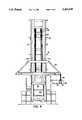
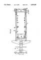
- FIG. 4is a front elevational view of the transporter depicted in FIGS. 1-3 showing the carriage pick-up with the lift frame suspended therefrom partially broken away;
- FIG. 6is a plan view of the frame depicted in FIG. 5;
- FIG. 7is a side elevational view showing the upright extended to full height depicting the visibility vertically and horizontally in a stacking operation and to the rear for backing up;
- FIG. 8shows the upright partially extended for visibility through the upright and beneath a container being moved in the transport mode
- FIG. 9shows a hydraulic lift circuit for sensing loads or engine speed to match lift speed with the load.
- FIG. 1in a preferred embodiment of the invention there is shown a container transporter vehicle having a body 10 supported on rear wheels 11 from which the vehicle is steered and drive wheels 12 from which it is propelled in either forward or reverse.
- the body 10has a deck 13 reached by stairways 14 and 15 (FIGS. 2 and 3) on either side of the vehicle for accessing an operator's cab 16. Mounting or dismounting from the deck 13 is assisted by handrails 17 and 18.
- the cabmay be entered through doors 20 on opposite sides of the cab to reach an operator's station having a seat (not shown) facing a console with control levers and gauges situated in the cab for maximum forward or reverse visibility.
- the cabis constructed with a wide angle, wraparound front window 22 that extends from one side of the operator's station to the other (FIG. 2) inclined to the rear such that front trapezoidal panels 23, 24, 25 are at such an angle with the vertical so as to permit the range of vision from the operator's station to above the height of a stack of four ISO containers (FIG. 7) and extending below the operator's station to permit a line of sight at the front of the vehicle where containers would be spotted on the tarmac.
- Right and left panels 23 and 25form a narrow seam with the center trapezoidal panel 24 without the assistance of any frame or divider other than a very narrow rubberized seal creating a more or less continuous horizontal expanse of window area across the front and partially on either side of the operator's station for viewing the lift frame when fully extended or collapsed.
- an upright or mast structure 29having a movable inner rail section 30 which can be hydraulically extended upwardly on roller sets from parallel outer fixed rails 31 by means of a hydraulic cylinder 34, which lifts against a cross-member 36, having a chain sheave 37, over which travels a chain 38, fastened at one end to a carriage pick-up 40, traveling on rollers (not shown) on the inner rail section 30, and fastened at the other end to chain anchors (not shown) in cross member 36.
- the cross member 41spans across the back of the outer rails providing lateral strength.
- the carriage pick-up 40supports a pick-up frame structure 42, (FIG. 4) from which is suspended a lift frame 44 by chains 45. Twist locks 48 at the corners of the telescoping ends of the lift frame are brought into engagement with locking receptacles 50 (FIGS. 7-8) in the upper corners of the container 52, allowing it to be lifted and transported; the transport position is depicted in FIG. 8.
- the lift frame 44can be laterally extended by telescoping out the ends in opposite directions to align the twist locks 48 above the container locking receptacles 50 for either twenty or forty foot long containers.
- a counterweight 60 mounted at the rear of the transporterpartially counterbalances the load of a container 52 being lifted at the front by the upright which can be tilted forwards or backwards (FIG. 3) from vertical as required by a pair of hydraulic tilt cylinders 49.
- An engine 54shown in dotted lines in FIG. 3, has an exhaust pipe 55 the front end of which enters an opening 56 in the outer rail 31 which is closed off throughout its length to form a tube 57 exhausting engine gases out the upper end 58 and away from the cab 16.
- the transporter frame 62has a rear counterweight frame portion 64 on which the counterweight 60 is mounted by means of a bracket 65 and a tower structure 66 behind the medial point of the frame 62 for supporting the cab structure 16 in a pivotal manner allowing the cab to be swung rearwardly for servicing the engine 54 (FIG. 1) and pivotally supporting at 63 the pair of tilt cylinders 49.
- the frame 62is comprised of two parallel side rail members 69, 70 which are structurally interconnected at the front by cross-member 72, fabricated as a structural member for the frame but also as an axle housing having hub plates 73, one at each end, for mounting gear reduction planetary hubs (not shown) driven from a differential housed in a belled-out portion 74 of the housing 72.
- Engine 54has a coupled torque converter for driving the wheels 12 and propelling the unit.
- the gear reduction planetary hubs on which the wheels 12 are mountedare driven by axle shafts passing through openings 83 in the ends of the hub plates 73.
- Fabricated at the ends of each frame rail 69, 70are upright bracket arms 80, which pivotally support at 82 the lower ends of the upright outer rails 31.
- the track width of the wheels 12is narrower because of the fabricated upright bracket arm being on the frame rails allowing the wheels to be closer. This provides greater visibility since the wheels do not obscure the ends of the containers when spotting.
- the inner rails 30are tied together at their lower ends by cross-member 90, which in the lowered position of the upright terminates above the lower ends of the outer rails 31.
- the outer rails 31are longer by this amount, the overall effect being to reduce the cross sectional thickness of the upright in the lowered position (dotted line position in FIG.
- the body 26is recessed at the front 94 behind the bell housing 74 to provide even greater visibility from the cab over the bell housing through the upright and out to a distance in front of the machine sufficient to enable the operator to accurately and rapidly spot a container on a predetermined line on the tarmac.
- the container transporterwill pick up, transport, stack or spot containers 52 to a stack height of four standard ISO containers as depicted in FIG. 7.
- the operator's line of sight from the operator's station in the cab 16will range from a line 95 observing the locking receptacles 50 of the container 52 being picked up or deposited onto a stack (shown in dotted lines) setting on the tarmac.
- the operatoralso has a view along the line 96 of the opposite corner of the container 52 being manipulated, and looking downwardly along line 97 to the front corner of the tarmac, he can place a first container accurately along the spotting lines drawn on the tarmac.
- the operatorhas a clear view out the back along line of sight 98 and can observe, before backing up, whether there are any objects or other hazards to operate the machine in reverse.
- the operatorhas (as shown in FIG. 8) a view through the upright beneath the container 52 while transporting it as shown by the line of sight 99 below the partially raised inner rails 30.
- FIG. 9a portion of the hydraulic circuit is depicted where three gear pumps 100, 102, 103 are driven off the torque converter at engine speed each having an independent circuit for functional applications required in operation of the container handler including a steering circuit 105 served by pump 100, a lifting circuit 107 connected to the pump 102 and a brake circuit 108 served by pump 103, however circuits 105 and 108 are also interdependent with lift circuit 107 to allow all three pumps to be connected to the lift circuit depending upon the sensing of engine speed or the weight of a load being lifted by the upright.
- the steering circuit 105includes a steering valve 112 connected to the pump 100 by hydraulic line 113 the output of which is directed to a steering cylinder, represented by the block 114, mounted at the rear between the frame and steer axle for steering the transporter in a known manner. Hydraulic lines 115 and 116 connect the steering valve 112 to the steering cylinder. Line 120 also connects the output of pump 100 to the lift circuit. The lift circuit 107 connects the output of pump 102 to the hydraulic cylinder 34 through line 118 for raising and lowering the upright 29.
- a diverter valve 127senses engine speed and at 1800 rpm shifts to combine the output of pump 103 with that of pumps 100 and 102 in line 118 to achieve the highest lift speed when the engine can operate at high rpms and low torque output because of handling light loads or empty containers.
- Another diverter valve 125operates according to differential pressure sensed because of check valve 117 between ends 120 and 119 and when the differential pressure exceeds 1500 psi, valve 125 diverts the output of pump 100 to reservoir 130 and because of low engine speeds valve 127 also diverts the output of pump 103 to reservoir 129, such that when the loading conditions exceed both the differential pressure setting and engine speed setting, the torque output is maximized or prioritized for the lift circuit 107 and pumps 100 and 103 are diverted out of the system and only pump 102 is connected to the lift circuit conserving the engine torque for lifting at low speed maximum load conditions.
- the diverter valve 125, 127both are shifted in the direction to deliver the output of pumps 100,103 through line 118 to the lift cylinder 34 to provide maximum fluid flow to the lift circuit achieving higher speeds of lift than would otherwise be possible without overloading the engine.
- the maximum engine torquewill be required for operating pump 102 and at the lower engine speed, and high differential pressure valves 125, 127 will divert the output of both pumps 100 and 103 to reservoirs 129, 130 such that the maximum torque of the engine is committed to operating pump 102 thus matching the load with the engine torque.
- valve 125, 127will be shifted to divert the output of either pump 100 or 103 as conditions require, to change the lift speed according to engine speed or pressure differential conditions, such that the lift speed is more nearly matched to the engine torque output and weight of the load to achieve the optimum lift speed under those given conditions.
Landscapes
- Engineering & Computer Science (AREA)
- Transportation (AREA)
- Structural Engineering (AREA)
- Civil Engineering (AREA)
- Life Sciences & Earth Sciences (AREA)
- Geology (AREA)
- Mechanical Engineering (AREA)
- Forklifts And Lifting Vehicles (AREA)
Abstract
Description
Claims (10)
Priority Applications (2)
| Application Number | Priority Date | Filing Date | Title |
|---|---|---|---|
| US07/682,758US5201629A (en) | 1991-04-09 | 1991-04-09 | Container transporter |
| PT100358APT100358B (en) | 1991-04-09 | 1992-04-08 | CONTAINER CONVEYOR VEHICLE |
Applications Claiming Priority (1)
| Application Number | Priority Date | Filing Date | Title |
|---|---|---|---|
| US07/682,758US5201629A (en) | 1991-04-09 | 1991-04-09 | Container transporter |
Publications (1)
| Publication Number | Publication Date |
|---|---|
| US5201629Atrue US5201629A (en) | 1993-04-13 |
Family
ID=24741011
Family Applications (1)
| Application Number | Title | Priority Date | Filing Date |
|---|---|---|---|
| US07/682,758Expired - Fee RelatedUS5201629A (en) | 1991-04-09 | 1991-04-09 | Container transporter |
Country Status (2)
| Country | Link |
|---|---|
| US (1) | US5201629A (en) |
| PT (1) | PT100358B (en) |
Cited By (47)
| Publication number | Priority date | Publication date | Assignee | Title |
|---|---|---|---|---|
| USD376243S (en) | 1995-02-27 | 1996-12-03 | Manitou Bf | Lift truck |
| US6182797B1 (en)* | 1998-03-17 | 2001-02-06 | Crown Equipment Corporation | Enhanced visibility rider reach fork lift truck |
| US20030158638A1 (en)* | 1999-07-30 | 2003-08-21 | Oshkosh Truck Corporation | Control system and method for electric vehicle |
| US20030205422A1 (en)* | 2002-05-02 | 2003-11-06 | Oshkosh Truck Corporation | Hybrid vehicle with combustion engine/electric motor drive |
| US6695567B2 (en)* | 2000-02-28 | 2004-02-24 | Kabushiki Kaisha Toyoda Jidoshokki Seisakusho | Hydraulic device for industrial vehicles |
| US20040133332A1 (en)* | 2001-01-31 | 2004-07-08 | Oshkosh Truck Corporation | A/C bus assembly for electronic traction vehicle |
| US20050113988A1 (en)* | 2001-12-21 | 2005-05-26 | Oshkosh Truck Corporation | Failure mode operation for an electric vehicle |
| US20050114007A1 (en)* | 2001-12-21 | 2005-05-26 | Oshkosh Truck Corporation | Multi-network control system for a vehicle |
| US20050119806A1 (en)* | 2001-01-31 | 2005-06-02 | Oshkosh Truck Corporation | System and method for braking in an electric vehicle |
| US20060016639A1 (en)* | 2004-05-26 | 2006-01-26 | Mike Wiggins | Forklift upright assembly |
| US6994223B1 (en)* | 2002-10-29 | 2006-02-07 | Auto Crane Company | Diagnostic readout for operation of a crane |
| US20060071645A1 (en)* | 2004-09-27 | 2006-04-06 | Oshkosh Truck Corporation | Status indicator for an energy storage device for use with an electric vehicle |
| US20060180382A1 (en)* | 2004-05-04 | 2006-08-17 | Andreas Scheidl | Telescopic loader, in particular a reach stacker |
| US20070185625A1 (en)* | 1999-07-30 | 2007-08-09 | Oshkosh Truck Corporation | Turret envelope control system and method for a fire fighting vehicle |
| WO2006113363A3 (en)* | 2005-04-14 | 2007-10-11 | Nmhg Oregon Llc | Hydraulic system for an industrial vehicle |
| US20070281826A1 (en)* | 2006-06-05 | 2007-12-06 | Jahmy Hindman | Power management for infinitely variable transmission (IVT) equipped machines |
| US20070288131A1 (en)* | 2001-01-31 | 2007-12-13 | Oshkosh Truck Corporation | Control system and method for electric vehicle |
| US20070291130A1 (en)* | 2006-06-19 | 2007-12-20 | Oshkosh Truck Corporation | Vision system for an autonomous vehicle |
| EP2008961A1 (en)* | 2007-06-29 | 2008-12-31 | BT Products AB | Control unit, method and computer program product for controlling a lift mechanism |
| US20090200836A1 (en)* | 2008-02-12 | 2009-08-13 | Aaron Alls | Gusseted torsion system for an open frame vehicle |
| US7628418B1 (en) | 2006-01-17 | 2009-12-08 | Holmes & Holmes, Ltd. | Low profile dolly trailer for hauling large cylindrical objects |
| US7835838B2 (en) | 1999-07-30 | 2010-11-16 | Oshkosh Corporation | Concrete placement vehicle control system and method |
| US8337352B2 (en) | 2010-06-22 | 2012-12-25 | Oshkosh Corporation | Electromechanical variable transmission |
| US8947531B2 (en) | 2006-06-19 | 2015-02-03 | Oshkosh Corporation | Vehicle diagnostics based on information communicated between vehicles |
| US20150142278A1 (en)* | 2013-11-19 | 2015-05-21 | Nacco Materials Handling Group, Inc. | Reverse Drive Handle For Lift Truck |
| US9114804B1 (en) | 2013-03-14 | 2015-08-25 | Oshkosh Defense, Llc | Vehicle drive and method with electromechanical variable transmission |
| CN105197839A (en)* | 2015-01-15 | 2015-12-30 | 徐州重型机械有限公司 | Combined support and stacking machine frame provided with combined support |
| US9651120B2 (en) | 2015-02-17 | 2017-05-16 | Oshkosh Corporation | Multi-mode electromechanical variable transmission |
| US9650032B2 (en) | 2015-02-17 | 2017-05-16 | Oshkosh Corporation | Multi-mode electromechanical variable transmission |
| US9656659B2 (en) | 2015-02-17 | 2017-05-23 | Oshkosh Corporation | Multi-mode electromechanical variable transmission |
| CN110167868A (en)* | 2016-11-09 | 2019-08-23 | 艾克森特法国 | The method of mobile base and transport equipment for transport equipment |
| US10421350B2 (en) | 2015-10-20 | 2019-09-24 | Oshkosh Corporation | Inline electromechanical variable transmission system |
| US20190322503A1 (en)* | 2016-07-08 | 2019-10-24 | Up Lifting Vertical, S.A. | Forklift for air transport and stowage procedure |
| US10578195B2 (en) | 2015-02-17 | 2020-03-03 | Oshkosh Corporation | Inline electromechanical variable transmission system |
| US10584775B2 (en) | 2015-02-17 | 2020-03-10 | Oshkosh Corporation | Inline electromechanical variable transmission system |
| US20200079631A1 (en)* | 2017-03-31 | 2020-03-12 | Elme Spreader Ab | Side lift spreader for lifting intermodal containers, and method of operating a side lift spreader |
| US10822216B2 (en)* | 2016-06-10 | 2020-11-03 | Altec Industries, Inc. | Modular rib for elevating platform |
| US10889478B2 (en)* | 2015-12-09 | 2021-01-12 | Haulotte Group | Control console and aerial lift including such a control console |
| US10968090B2 (en) | 2016-06-10 | 2021-04-06 | Altec Industries, Inc. | Modular rib for elevating platform |
| US10982736B2 (en) | 2015-02-17 | 2021-04-20 | Oshkosh Corporation | Multi-mode electromechanical variable transmission |
| US11306867B2 (en) | 2016-06-10 | 2022-04-19 | Altec Industries, Inc. | Mounting system for elevating platform |
| EP3026002B1 (en)* | 2012-02-20 | 2022-05-11 | Elme Spreader AB | Side lift spreader |
| US11701959B2 (en) | 2015-02-17 | 2023-07-18 | Oshkosh Corporation | Inline electromechanical variable transmission system |
| US11987483B2 (en) | 2020-06-05 | 2024-05-21 | Crown Equipment Corporation | Operator control system for a materials handling vehicle |
| US11993497B2 (en) | 2015-11-09 | 2024-05-28 | Crown Equipment Corporation | Order picker materials handling vehicle with improved downward visibility when driving elevated |
| US12078231B2 (en) | 2015-02-17 | 2024-09-03 | Oshkosh Corporation | Inline electromechanical variable transmission system |
| US12187588B2 (en) | 2016-06-10 | 2025-01-07 | Altec Industries, Inc. | Modular rib |
Citations (20)
| Publication number | Priority date | Publication date | Assignee | Title |
|---|---|---|---|---|
| US1867802A (en)* | 1930-05-17 | 1932-07-19 | Bogert Clara | Exhaust gas and odor eliminator for motor vehicles |
| US2503181A (en)* | 1948-07-14 | 1950-04-04 | Eddie B Wagner | Trussed track tower vehicle |
| US2661958A (en)* | 1952-07-11 | 1953-12-08 | Benjamin E Stokes | Wheel and axle assembly for tobacco truck chassis |
| US2936044A (en)* | 1957-02-19 | 1960-05-10 | Yale & Towne Mfg Co | Channel construction for industrial truck |
| US3135347A (en)* | 1962-02-07 | 1964-06-02 | Louis M Vranyosovics | Exhaust system |
| US3568868A (en)* | 1969-09-08 | 1971-03-09 | Clark Equipment Co | Hydraulic system for a lift truck |
| US3595343A (en)* | 1969-01-15 | 1971-07-27 | Clark Equipment Co | Control system for lift trucks |
| US3688933A (en)* | 1970-12-07 | 1972-09-05 | James A Rumell | Lifting attachment for fork lift trucks and the like |
| US3764032A (en)* | 1971-12-09 | 1973-10-09 | Clark Equipment Co | Container handling device |
| USRE27905E (en)* | 1972-04-12 | 1974-01-29 | Certificate of correction | |
| US3802530A (en)* | 1972-04-26 | 1974-04-09 | Deere & Co | Tractor cab |
| US3866969A (en)* | 1973-08-16 | 1975-02-18 | Fiat Allis Construct Machine | Operator{40 s compartment with swinging window |
| US3918546A (en)* | 1973-11-21 | 1975-11-11 | Clark Equipment Co | Hydrostatic assist drive for vehicles |
| US4023650A (en)* | 1975-08-20 | 1977-05-17 | Eaton Corporation | Hydraulic systems for two speed lifting |
| US4147034A (en)* | 1978-04-19 | 1979-04-03 | Caterpillar Tractor Co. | Hydraulic system with priority control |
| US4382485A (en)* | 1980-05-27 | 1983-05-10 | Dresser Industries, Inc. | Hydraulic logic control for variable displacement pump |
| US4449882A (en)* | 1982-05-20 | 1984-05-22 | Scott S. Corbett, Jr. | Apparatus for carrying empty cargo containers |
| US4506747A (en)* | 1982-09-20 | 1985-03-26 | Deere & Company | Axle tube and hydraulic motor housing mounting arrangement |
| US4552250A (en)* | 1983-04-22 | 1985-11-12 | Crown Controls Corporation | Lift truck |
| US4995469A (en)* | 1989-09-25 | 1991-02-26 | Caterpillar Industrial Inc. | Operator's station mounting arrangement and method |
- 1991
- 1991-04-09USUS07/682,758patent/US5201629A/ennot_activeExpired - Fee Related
- 1992
- 1992-04-08PTPT100358Apatent/PT100358B/ennot_activeIP Right Cessation
Patent Citations (20)
| Publication number | Priority date | Publication date | Assignee | Title |
|---|---|---|---|---|
| US1867802A (en)* | 1930-05-17 | 1932-07-19 | Bogert Clara | Exhaust gas and odor eliminator for motor vehicles |
| US2503181A (en)* | 1948-07-14 | 1950-04-04 | Eddie B Wagner | Trussed track tower vehicle |
| US2661958A (en)* | 1952-07-11 | 1953-12-08 | Benjamin E Stokes | Wheel and axle assembly for tobacco truck chassis |
| US2936044A (en)* | 1957-02-19 | 1960-05-10 | Yale & Towne Mfg Co | Channel construction for industrial truck |
| US3135347A (en)* | 1962-02-07 | 1964-06-02 | Louis M Vranyosovics | Exhaust system |
| US3595343A (en)* | 1969-01-15 | 1971-07-27 | Clark Equipment Co | Control system for lift trucks |
| US3568868A (en)* | 1969-09-08 | 1971-03-09 | Clark Equipment Co | Hydraulic system for a lift truck |
| US3688933A (en)* | 1970-12-07 | 1972-09-05 | James A Rumell | Lifting attachment for fork lift trucks and the like |
| US3764032A (en)* | 1971-12-09 | 1973-10-09 | Clark Equipment Co | Container handling device |
| USRE27905E (en)* | 1972-04-12 | 1974-01-29 | Certificate of correction | |
| US3802530A (en)* | 1972-04-26 | 1974-04-09 | Deere & Co | Tractor cab |
| US3866969A (en)* | 1973-08-16 | 1975-02-18 | Fiat Allis Construct Machine | Operator{40 s compartment with swinging window |
| US3918546A (en)* | 1973-11-21 | 1975-11-11 | Clark Equipment Co | Hydrostatic assist drive for vehicles |
| US4023650A (en)* | 1975-08-20 | 1977-05-17 | Eaton Corporation | Hydraulic systems for two speed lifting |
| US4147034A (en)* | 1978-04-19 | 1979-04-03 | Caterpillar Tractor Co. | Hydraulic system with priority control |
| US4382485A (en)* | 1980-05-27 | 1983-05-10 | Dresser Industries, Inc. | Hydraulic logic control for variable displacement pump |
| US4449882A (en)* | 1982-05-20 | 1984-05-22 | Scott S. Corbett, Jr. | Apparatus for carrying empty cargo containers |
| US4506747A (en)* | 1982-09-20 | 1985-03-26 | Deere & Company | Axle tube and hydraulic motor housing mounting arrangement |
| US4552250A (en)* | 1983-04-22 | 1985-11-12 | Crown Controls Corporation | Lift truck |
| US4995469A (en)* | 1989-09-25 | 1991-02-26 | Caterpillar Industrial Inc. | Operator's station mounting arrangement and method |
Non-Patent Citations (2)
| Title |
|---|
| Clark C500Y800D Brochure, 1978 (16 pages) supplied by applicant as prior art.* |
| Clark C500Y800D Specification Sheet, 1978 (2 pages) supplied by applicant as prior art.* |
Cited By (102)
| Publication number | Priority date | Publication date | Assignee | Title |
|---|---|---|---|---|
| USD376243S (en) | 1995-02-27 | 1996-12-03 | Manitou Bf | Lift truck |
| US6182797B1 (en)* | 1998-03-17 | 2001-02-06 | Crown Equipment Corporation | Enhanced visibility rider reach fork lift truck |
| US20070185625A1 (en)* | 1999-07-30 | 2007-08-09 | Oshkosh Truck Corporation | Turret envelope control system and method for a fire fighting vehicle |
| US20030158638A1 (en)* | 1999-07-30 | 2003-08-21 | Oshkosh Truck Corporation | Control system and method for electric vehicle |
| US7835838B2 (en) | 1999-07-30 | 2010-11-16 | Oshkosh Corporation | Concrete placement vehicle control system and method |
| US6885920B2 (en) | 1999-07-30 | 2005-04-26 | Oshkosh Truck Corporation | Control system and method for electric vehicle |
| US8095247B2 (en) | 1999-07-30 | 2012-01-10 | Oshkosh Corporation | Turret envelope control system and method for a vehicle |
| US6695567B2 (en)* | 2000-02-28 | 2004-02-24 | Kabushiki Kaisha Toyoda Jidoshokki Seisakusho | Hydraulic device for industrial vehicles |
| US7848857B2 (en) | 2001-01-31 | 2010-12-07 | Oshkosh Corporation | System and method for braking in an electric vehicle |
| US20050119806A1 (en)* | 2001-01-31 | 2005-06-02 | Oshkosh Truck Corporation | System and method for braking in an electric vehicle |
| US20040133332A1 (en)* | 2001-01-31 | 2004-07-08 | Oshkosh Truck Corporation | A/C bus assembly for electronic traction vehicle |
| US7711460B2 (en) | 2001-01-31 | 2010-05-04 | Oshkosh Corporation | Control system and method for electric vehicle |
| US7379797B2 (en) | 2001-01-31 | 2008-05-27 | Oshkosh Truck Corporation | System and method for braking in an electric vehicle |
| US20080059014A1 (en)* | 2001-01-31 | 2008-03-06 | Oshkosh Truck Corporation | System and method for braking in an electric vehicle |
| US20070288131A1 (en)* | 2001-01-31 | 2007-12-13 | Oshkosh Truck Corporation | Control system and method for electric vehicle |
| US7164977B2 (en) | 2001-01-31 | 2007-01-16 | Oshkosh Truck Corporation | A/C bus assembly for electronic traction vehicle |
| US8000850B2 (en) | 2001-12-21 | 2011-08-16 | Oshkosh Truck Corporation | Failure mode operation for an electric vehicle |
| US7254468B2 (en) | 2001-12-21 | 2007-08-07 | Oshkosh Truck Corporation | Multi-network control system for a vehicle |
| US7302320B2 (en) | 2001-12-21 | 2007-11-27 | Oshkosh Truck Corporation | Failure mode operation for an electric vehicle |
| US20050113988A1 (en)* | 2001-12-21 | 2005-05-26 | Oshkosh Truck Corporation | Failure mode operation for an electric vehicle |
| US20050114007A1 (en)* | 2001-12-21 | 2005-05-26 | Oshkosh Truck Corporation | Multi-network control system for a vehicle |
| US20030205422A1 (en)* | 2002-05-02 | 2003-11-06 | Oshkosh Truck Corporation | Hybrid vehicle with combustion engine/electric motor drive |
| US20090194347A1 (en)* | 2002-05-02 | 2009-08-06 | Oshkosh Corporation | Hybrid vehicle with combustion engine/electric motor drive |
| US7520354B2 (en)* | 2002-05-02 | 2009-04-21 | Oshkosh Truck Corporation | Hybrid vehicle with combustion engine/electric motor drive |
| US6994223B1 (en)* | 2002-10-29 | 2006-02-07 | Auto Crane Company | Diagnostic readout for operation of a crane |
| US20060180382A1 (en)* | 2004-05-04 | 2006-08-17 | Andreas Scheidl | Telescopic loader, in particular a reach stacker |
| US20060016639A1 (en)* | 2004-05-26 | 2006-01-26 | Mike Wiggins | Forklift upright assembly |
| US7134527B2 (en)* | 2004-05-26 | 2006-11-14 | Mike Wiggins | Forklift upright assembly |
| US7439711B2 (en) | 2004-09-27 | 2008-10-21 | Oshkosh Corporation | Energy storage device including a status indicator |
| US20060071645A1 (en)* | 2004-09-27 | 2006-04-06 | Oshkosh Truck Corporation | Status indicator for an energy storage device for use with an electric vehicle |
| EP1868935A4 (en)* | 2005-04-14 | 2010-06-30 | Nacco Materials Handling Group | HYDRAULIC SYSTEM OF AN INDUSTRIAL VEHICLE |
| WO2006113363A3 (en)* | 2005-04-14 | 2007-10-11 | Nmhg Oregon Llc | Hydraulic system for an industrial vehicle |
| US7628418B1 (en) | 2006-01-17 | 2009-12-08 | Holmes & Holmes, Ltd. | Low profile dolly trailer for hauling large cylindrical objects |
| US9126598B2 (en)* | 2006-06-05 | 2015-09-08 | Deere & Company | Power management for infinitely variable transmission (IVT) equipped machines |
| US20070281826A1 (en)* | 2006-06-05 | 2007-12-06 | Jahmy Hindman | Power management for infinitely variable transmission (IVT) equipped machines |
| US20070291130A1 (en)* | 2006-06-19 | 2007-12-20 | Oshkosh Truck Corporation | Vision system for an autonomous vehicle |
| US9420203B2 (en) | 2006-06-19 | 2016-08-16 | Oshkosh Defense, Llc | Vision system for a vehicle |
| US8139109B2 (en) | 2006-06-19 | 2012-03-20 | Oshkosh Corporation | Vision system for an autonomous vehicle |
| US8947531B2 (en) | 2006-06-19 | 2015-02-03 | Oshkosh Corporation | Vehicle diagnostics based on information communicated between vehicles |
| WO2009003833A1 (en)* | 2007-06-29 | 2009-01-08 | Bt Products Ab | Control unit, method and computer program product for controlling a lift mechanism |
| EP2008961A1 (en)* | 2007-06-29 | 2008-12-31 | BT Products AB | Control unit, method and computer program product for controlling a lift mechanism |
| US20090200836A1 (en)* | 2008-02-12 | 2009-08-13 | Aaron Alls | Gusseted torsion system for an open frame vehicle |
| US8337352B2 (en) | 2010-06-22 | 2012-12-25 | Oshkosh Corporation | Electromechanical variable transmission |
| US10843549B2 (en) | 2010-06-22 | 2020-11-24 | Oshkosh Defense, Llc | Electromechanical variable transmission |
| US10457134B2 (en) | 2010-06-22 | 2019-10-29 | Oshkosh Defense, Llc | Electromechanical variable transmission |
| US10029556B2 (en) | 2010-06-22 | 2018-07-24 | Oshkosh Defense, Llc | Electromechanical variable transmission |
| US8864613B2 (en) | 2010-06-22 | 2014-10-21 | Oshkosh Corporation | Electromechanical variable transmission |
| US9428042B2 (en) | 2010-06-22 | 2016-08-30 | Oshkosh Defense, Llc | Electromechanical variable transmission |
| EP3026002B1 (en)* | 2012-02-20 | 2022-05-11 | Elme Spreader AB | Side lift spreader |
| US9452750B2 (en) | 2013-03-14 | 2016-09-27 | Oshkosh Defense, Llc | Methods, systems, and vehicles with electromechanical variable transmission |
| US11299139B2 (en) | 2013-03-14 | 2022-04-12 | Oshkosh Defense, Llc | Drive train for a vehicle |
| US9114804B1 (en) | 2013-03-14 | 2015-08-25 | Oshkosh Defense, Llc | Vehicle drive and method with electromechanical variable transmission |
| US12214770B2 (en) | 2013-03-14 | 2025-02-04 | Oshkosh Defense, Llc | Drive train for a vehicle |
| US11827207B2 (en) | 2013-03-14 | 2023-11-28 | Oshkosh Defense, Llc | Drive train for a vehicle |
| US9376102B1 (en) | 2013-03-14 | 2016-06-28 | Oshkosh Defense, Llc | Vehicle drive and method with electromechanical variable transmission |
| US9821789B2 (en) | 2013-03-14 | 2017-11-21 | Oshkosh Defense, Llc | Vehicle drive and method with electromechanical variable transmission |
| US11052899B2 (en) | 2013-03-14 | 2021-07-06 | Oshkosh Defense, Llc | Vehicle drive and method with electromechanical variable transmission |
| US11440527B2 (en) | 2013-03-14 | 2022-09-13 | Oshkosh Defense, Llc | Methods and systems for vehicle drive |
| US10392000B2 (en) | 2013-03-14 | 2019-08-27 | Oshkosh Defense, Llc | Vehicle drive and method with electromechanical variable transmission |
| US9132736B1 (en) | 2013-03-14 | 2015-09-15 | Oshkosh Defense, Llc | Methods, systems, and vehicles with electromechanical variable transmission |
| US10315643B2 (en) | 2013-03-14 | 2019-06-11 | Oshkosh Defense, Llc | Methods, systems, and vehicles with electromechanical variable transmission |
| US20150142278A1 (en)* | 2013-11-19 | 2015-05-21 | Nacco Materials Handling Group, Inc. | Reverse Drive Handle For Lift Truck |
| US9561944B2 (en)* | 2013-11-19 | 2017-02-07 | Hyster-Yale Group, Inc. | Reverse drive handle for lift truck |
| CN105197839A (en)* | 2015-01-15 | 2015-12-30 | 徐州重型机械有限公司 | Combined support and stacking machine frame provided with combined support |
| CN105197839B (en)* | 2015-01-15 | 2017-11-28 | 徐州重型机械有限公司 | Modular support and the stacker vehicle frame that modular support is set |
| US11701959B2 (en) | 2015-02-17 | 2023-07-18 | Oshkosh Corporation | Inline electromechanical variable transmission system |
| US10989279B2 (en) | 2015-02-17 | 2021-04-27 | Oshkosh Corporation | Multi-mode electromechanical variable transmission |
| US10578195B2 (en) | 2015-02-17 | 2020-03-03 | Oshkosh Corporation | Inline electromechanical variable transmission system |
| US10584775B2 (en) | 2015-02-17 | 2020-03-10 | Oshkosh Corporation | Inline electromechanical variable transmission system |
| US12078231B2 (en) | 2015-02-17 | 2024-09-03 | Oshkosh Corporation | Inline electromechanical variable transmission system |
| US9650032B2 (en) | 2015-02-17 | 2017-05-16 | Oshkosh Corporation | Multi-mode electromechanical variable transmission |
| US9656659B2 (en) | 2015-02-17 | 2017-05-23 | Oshkosh Corporation | Multi-mode electromechanical variable transmission |
| US9908520B2 (en) | 2015-02-17 | 2018-03-06 | Oshkosh Corporation | Multi-mode electromechanical variable transmission |
| US12228195B2 (en) | 2015-02-17 | 2025-02-18 | Oshkosh Corporation | Driveline for electrified vehicle |
| US10160438B2 (en) | 2015-02-17 | 2018-12-25 | Oshkosh Corporation | Multi-mode electromechanical variable transmission |
| US10935112B2 (en) | 2015-02-17 | 2021-03-02 | Oshkosh Corporation | Inline electromechanical variable transmission system |
| US10967728B2 (en) | 2015-02-17 | 2021-04-06 | Oshkosh Corporation | Multi-mode electromechanical variable transmission |
| US9651120B2 (en) | 2015-02-17 | 2017-05-16 | Oshkosh Corporation | Multi-mode electromechanical variable transmission |
| US10974713B2 (en) | 2015-02-17 | 2021-04-13 | Oshkosh Corporation | Multi-mode electromechanical variable transmission |
| US10982736B2 (en) | 2015-02-17 | 2021-04-20 | Oshkosh Corporation | Multi-mode electromechanical variable transmission |
| US11009104B2 (en) | 2015-02-17 | 2021-05-18 | Oshkosh Corporation | Inline electromechanical variable transmission system |
| US11007860B2 (en) | 2015-10-20 | 2021-05-18 | Oshkosh Corporation | Inline electromechanical variable transmission system |
| US10421350B2 (en) | 2015-10-20 | 2019-09-24 | Oshkosh Corporation | Inline electromechanical variable transmission system |
| US11993497B2 (en) | 2015-11-09 | 2024-05-28 | Crown Equipment Corporation | Order picker materials handling vehicle with improved downward visibility when driving elevated |
| US10889478B2 (en)* | 2015-12-09 | 2021-01-12 | Haulotte Group | Control console and aerial lift including such a control console |
| US20210039933A1 (en)* | 2016-06-10 | 2021-02-11 | Altec Industries, Inc. | Modular rib for elevating platform |
| US11306867B2 (en) | 2016-06-10 | 2022-04-19 | Altec Industries, Inc. | Mounting system for elevating platform |
| US12187588B2 (en) | 2016-06-10 | 2025-01-07 | Altec Industries, Inc. | Modular rib |
| US12172874B2 (en)* | 2016-06-10 | 2024-12-24 | Altec Industries, Inc. | Modular rib for elevating platform |
| US10968090B2 (en) | 2016-06-10 | 2021-04-06 | Altec Industries, Inc. | Modular rib for elevating platform |
| US11725776B2 (en) | 2016-06-10 | 2023-08-15 | Altec Industries, Inc. | Mounting system for elevating platform |
| US10822216B2 (en)* | 2016-06-10 | 2020-11-03 | Altec Industries, Inc. | Modular rib for elevating platform |
| US12258245B2 (en) | 2016-06-10 | 2025-03-25 | Altec Industries, Inc. | Step system for elevating platform |
| US20190322503A1 (en)* | 2016-07-08 | 2019-10-24 | Up Lifting Vertical, S.A. | Forklift for air transport and stowage procedure |
| CN110167868B (en)* | 2016-11-09 | 2021-12-24 | 艾克森特法国 | Mobile base for a transfer device and method for transferring a device |
| US11377332B2 (en)* | 2016-11-09 | 2022-07-05 | Excent France | Movable base and method for transporting equipment |
| CN110167868A (en)* | 2016-11-09 | 2019-08-23 | 艾克森特法国 | The method of mobile base and transport equipment for transport equipment |
| US20190284032A1 (en)* | 2016-11-09 | 2019-09-19 | Excent France | Movable base and method for transporting equipment |
| US10913642B2 (en)* | 2017-03-31 | 2021-02-09 | Elme Spreader Ab | Side lift spreader for lifting intermodal containers, and method of operating a side lift spreader |
| US20200079631A1 (en)* | 2017-03-31 | 2020-03-12 | Elme Spreader Ab | Side lift spreader for lifting intermodal containers, and method of operating a side lift spreader |
| US12071333B2 (en) | 2020-06-05 | 2024-08-27 | Crown Equipment Corporation | Vertical viewing windows in a materials handling vehicle |
| US11987483B2 (en) | 2020-06-05 | 2024-05-21 | Crown Equipment Corporation | Operator control system for a materials handling vehicle |
Also Published As
| Publication number | Publication date |
|---|---|
| PT100358B (en) | 1999-11-30 |
| PT100358A (en) | 1994-04-29 |
Similar Documents
| Publication | Publication Date | Title |
|---|---|---|
| US5201629A (en) | Container transporter | |
| US8714311B2 (en) | Monomast for a materials handling vehicle | |
| US3225949A (en) | Lift truck with load handling assembly mounted on a movable frame supported by the steering wheel of the truck | |
| US5415516A (en) | Compact trailer having hydraulic fork lift | |
| EP1829815B1 (en) | A forklift truck | |
| CA2624870C (en) | A materials handling vehicle with improved visibility | |
| US5582501A (en) | Fork lift and method for operating and transporting same | |
| US6435806B1 (en) | Pick-up vehicle having a swivel device, swivel device, and process for loading and unloading the pick-up vehicle | |
| US20040013504A1 (en) | Straddle carrier | |
| US5848870A (en) | Single person catering vehicle | |
| US6799935B1 (en) | Lifting apparatus for user in the bed of a pickup truck | |
| CA1106326A (en) | Hauling vehicle | |
| US4859133A (en) | Fork lift truck and vehicle for the transport thereof | |
| US4949816A (en) | Upright for lift truck | |
| US20030168286A1 (en) | Lift truck and lift truck operating method | |
| NZ193360A (en) | Upright structure for fork lift truck:lift cylinder offset for better vision | |
| US4374550A (en) | Upright for lift truck | |
| US4369861A (en) | Multiple section mast with a pair of lift jacks behind the primary section uprights | |
| EP0027811B1 (en) | Container truck for lifting and carrying away a container | |
| US5000293A (en) | Upright for lift truck | |
| US5320197A (en) | Sextuple upright | |
| WO1993007041A1 (en) | Container transporter | |
| KR200322579Y1 (en) | Crane Lift Truck | |
| GB2206097A (en) | Loading and unloading vehicles | |
| CA2087553C (en) | Fork-lift truck |
Legal Events
| Date | Code | Title | Description |
|---|---|---|---|
| AS | Assignment | Owner name:CLARK EQUIPMENT COMPANY, SOUTH BEND, IN A CORP. OF Free format text:ASSIGNMENT OF ASSIGNORS INTEREST.;ASSIGNORS:SIMPSON, CLARK;HODGMAN, JOHN;REEL/FRAME:005671/0592 Effective date:19910405 | |
| AS | Assignment | Owner name:CLARK MATERIAL HANDLING COMPANY, KENTUCKY Free format text:ASSIGNMENT OF ASSIGNORS INTEREST.;ASSIGNOR:CLARK EQUIPMENT COMPANY;REEL/FRAME:006409/0057 Effective date:19930105 | |
| AS | Assignment | Owner name:UNITED STATES TRUST COMPANY OF NEW YORK, NEW YORK Free format text:ASSIGNMENT OF ASSIGNORS INTEREST;ASSIGNOR:CLARK MATERIAL HANDLING COMPANY;REEL/FRAME:007476/0681 Effective date:19950509 | |
| FEPP | Fee payment procedure | Free format text:PAYOR NUMBER ASSIGNED (ORIGINAL EVENT CODE: ASPN); ENTITY STATUS OF PATENT OWNER: LARGE ENTITY | |
| FPAY | Fee payment | Year of fee payment:4 | |
| SULP | Surcharge for late payment | ||
| FEPP | Fee payment procedure | Free format text:PAYER NUMBER DE-ASSIGNED (ORIGINAL EVENT CODE: RMPN); ENTITY STATUS OF PATENT OWNER: LARGE ENTITY Free format text:PAYOR NUMBER ASSIGNED (ORIGINAL EVENT CODE: ASPN); ENTITY STATUS OF PATENT OWNER: LARGE ENTITY | |
| REMI | Maintenance fee reminder mailed | ||
| LAPS | Lapse for failure to pay maintenance fees | ||
| FP | Lapsed due to failure to pay maintenance fee | Effective date:20010413 | |
| STCH | Information on status: patent discontinuation | Free format text:PATENT EXPIRED DUE TO NONPAYMENT OF MAINTENANCE FEES UNDER 37 CFR 1.362 |