US5201530A - Multi-layered brush seal - Google Patents
Multi-layered brush sealDownload PDFInfo
- Publication number
- US5201530A US5201530AUS07/778,554US77855491AUS5201530AUS 5201530 AUS5201530 AUS 5201530AUS 77855491 AUS77855491 AUS 77855491AUS 5201530 AUS5201530 AUS 5201530A
- Authority
- US
- United States
- Prior art keywords
- bristles
- brush seal
- sectional area
- cross
- edge
- Prior art date
- Legal status (The legal status is an assumption and is not a legal conclusion. Google has not performed a legal analysis and makes no representation as to the accuracy of the status listed.)
- Expired - Lifetime
Links
- 239000012530fluidSubstances0.000claimsdescription4
- 239000000463materialSubstances0.000description2
- 238000007789sealingMethods0.000description2
- 241000904500Oxyspora paniculataSpecies0.000description1
- 230000004888barrier functionEffects0.000description1
- 238000005516engineering processMethods0.000description1
- 239000000835fiberSubstances0.000description1
- 230000003068static effectEffects0.000description1
- 238000003466weldingMethods0.000description1
Images


Classifications
- F—MECHANICAL ENGINEERING; LIGHTING; HEATING; WEAPONS; BLASTING
- F16—ENGINEERING ELEMENTS AND UNITS; GENERAL MEASURES FOR PRODUCING AND MAINTAINING EFFECTIVE FUNCTIONING OF MACHINES OR INSTALLATIONS; THERMAL INSULATION IN GENERAL
- F16J—PISTONS; CYLINDERS; SEALINGS
- F16J15/00—Sealings
- F16J15/16—Sealings between relatively-moving surfaces
- F16J15/32—Sealings between relatively-moving surfaces with elastic sealings, e.g. O-rings
- F16J15/3284—Sealings between relatively-moving surfaces with elastic sealings, e.g. O-rings characterised by their structure; Selection of materials
- F16J15/3288—Filamentary structures, e.g. brush seals
Definitions
- This inventionrelates to pressure seals for use between two components which move relative to each other.
- Brush sealsattached to a first component, are typically used to prevent the flow of a fluid from a high pressure region to a low pressure region along a second component which moves relative to the first component.
- Current brush seal technologytypically utilizes a plurality of constant diameter wire fiber bristles and a backing plate which supports those bristles along most of the length thereof. The backing plate is required to prevent excessive deflection of the bristles and the excessive leakage around the bristle tips which would result if the bristles were unsupported against the pressure load.
- Certain applications for brush sealssuch as gas turbine engines and exhaust nozzles, require the bristles to span relatively large gaps between the backing plate and the second component.
- Using the brush seals of the prior art to span such a distancetypically results in excessive leakage due to excessive bristle deflection.
- Extending the backing plate into near proximity of the second component to reduce the gap and the unsupported length of the bristlesmay result in interference between the backing plate and the second component, binding and/or damaging the second component at certain engine operating conditions.
- a brush sealhaving multiple layers of bristles and a backing plate.
- the individual bristles within a particular layerhave the same cross-sectional area or "thickness", and the layers are arranged in the order of increasing bristle thickness.
- the bristles of the layer that forms the high pressure face of the brush sealhave a relatively small cross-sectional area allowing them to be flexible and closely packed, thereby providing a low porosity barrier to the flow of fluid therethrough.
- the bristles of the layer forming the low pressure face of the brush sealare mounted next to the backing plate and have a substantially larger cross-sectional area, and are therefore significantly stiffer than the bristles of the high pressure face.
- each of the bristlesis secured in fixed relation to the backing plate thereby allowing each of the bristles to flex along the length thereof while maintaining the relative position of each bristle with respect to the other bristles.
- the backing plate of the present inventionprovides support for the larger cross-sectional area bristles, which in turn support the smaller cross-sectional area bristles against the pressure load, thereby preventing excessive deflection thereof. The result is a brush seal that provides effective sealing over a broader range of pressure loads than the brush seals of the prior art.
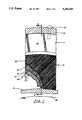
- FIG. 1is a partially cutaway view of the brush seal of the preferred embodiment of the present invention.
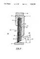
- FIG. 2is a cross-sectional view of the brush seal of the present invention taken along line 2--2 of FIG. 1.
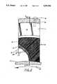
- FIG. 3is a partially cutaway view of a second embodiment of the brush seal of the present invention.
- FIG. 4is a cross-sectional view of a third embodiment of the brush seal of the present invention.
- FIG. 5is a partially cutaway view of a fifth embodiment of the brush seal of the present invention.
- FIG. 6is a partially cutaway view of a sixth embodiment of the brush seal of the present invention.
- the brush seal 10 of the present inventionincludes a shell 11 secured to a first component 12 by a bolt 13 or other suitable fastening means (such as a flange, and/or snap diametrial fit).
- the shell 11is preferably a channel having a head wall 14 and a backing plate 15.
- the brush seal 10has a layer of first bristles 16 extending toward a second component 17 which moves relative to the first component 12.
- the backing plate 15has an inner surface 18 facing the head wall 14.
- a layer of second bristles 19 made of the same material as the first bristles 16is sandwiched between the layer of first bristles 16 and the inner surface 18 of the backing plate 15.
- each of the second bristles 19is substantially larger than the cross-sectional area of the first bristles, and therefore, as those skilled in the art will readily appreciate, the second bristles 19 are substantially stiffer than the first bristles 16.
- the first and second bristles 16, 19are circular in cross-section with the diameter of each of the second bristles 19 being approximately twice the diameter of each of the first bristles 16.
- a third layer of bristles 20is included in the configuration.
- the third layer of bristles 20is sandwiched between the head wall 14 and the layer of first bristles 16.
- Each of the third bristles 20is made of the same material as the first bristles 16, but has a cross-sectional area substantially less, and preferably only about half, of the cross-sectional diameter of each of the first bristles 16.
- the first, second and third bristles 16, 19, 20are made of approximately 3 mil, 6 mil and 1.5 mil diameter wire, respectively, for the intended application, however, the specific diameter may change depending on the specific application.
- each of the first, second and third bristles 16, 19, 20is secured in fixed relation to the shell 11 preferably by welding the bristle ends 21 thereto.
- each of the first, second and third bristles 16, 19, 20extend into a gap 22 between the first component 12 and the second component 17, thereby defining the boundary between a high pressure region 23 and a low pressure region 24.
- the third bristles 20 in contact with the head wall 14thus form a portion of the high pressure face 25 of the brush seal 10
- the second bristles 19 in contact with the inner surface 18 of the backing wall 15form a portion of the low pressure face 26 of the brush seal 10.
- each of the layers of bristles 16, 19, 20is parallel to the inner surface 18 of the backing plate 15, and each of the first, second and third bristles 16, 19, 20 is canted in the direction of rotation at an angle 31 of approximately 45° to a tangent of the back plate edge 28, as shown in FIG. 1.
- the tip portion 27 of the first, second and third bristles 16, 19, 20extends beyond the edge 28 of the backing plate 15, terminating in proximate the second component 17, thereby substantially preventing fluid in the high pressure region 23 from flowing to the low pressure region 24 between the tip portion 27 and the second component 17.
- the first component 12is attached to a static structure and the second component 17 may have dynamic movement relative to component 12, thereby causing the tip of the first, second and third bristles 16, 19, 20 to become the location of movement between the first component 12 and the second component 17.
- the interstices of the closely packed bristles on the high pressure face 25 of the brush seal 10 and between the third bristles 20 and the second component 17,provide very little flow area.
- the pressure differential between the high pressure region 23 and the low pressure region 24tends to deflect the tip portion 27 of the third bristles 20 toward the first bristles 16, and under certain conditions the pressure differential between the high pressure region 23 and the low pressure region 24 may be so great that the stiffness of the tip portion 27 of the third bristles 20 alone may not be sufficient to prevent excessive deflection thereof.
- first and second bristles 16, 19which due to the greater stiffness provided by the larger cross-sectional area thereof, resist the maximum pressure differential occurring across brush seal 10.
- the first and second bristles 16, 19are, in turn, supported by the backing plate 15.
- the first and second bristles 16, 19provide some of the support to the third bristles 20 which, in the brush seals of the prior art, would have been provided by the backing plate 15, a larger gap 22 can be provided between the second component 17 and the edge 28 of the backing plate 15 in the present invention.
- the tip portion 27tapers at an angle 29 toward the first edge 28 as shown in FIG. 2, so that the third bristles 20 are in contact with the second component 17 when the gap 22 is at a nominal operating condition and so that the first bristles 16 only contact the second component 17 when the gap 22 has been typically reduced.
- the second bristles 19may contact the second component 17 as well.
- no interferenceoccurs between the backing plate 15 and the second component 17.
- FIG. 3A second embodiment of the present invention is shown in FIG. 3 which is identical to the preferred embodiment except the third layer of bristles 20 has been excluded.
- Each of the first and second bristles 16, 19extend into the gap 22 between the first component 12 and the second component 17, thereby defining the boundary between a high pressure region 23 and a low pressure region 24.
- each of the layers of bristles 16, 19is parallel to the inner surface 18 of backing plate 15, and each of the first and second bristles 16, 19 is canted in the direction of rotation at an angle 31 of approximately 45° to a tangent of the back plate edge 28, as shown in FIG. 3.
- the tip portion 27tapers at an angle 29 toward the first edge 28 such that the first bristles 16 are in contact with the second component 17 when the gap 22 is at a nominal operating condition and/or the gap 22 has been typically reduced.
- the second bristles 19may also contact the second component 17 as well.
- no interferenceoccurs between the backing plate 15 and the second component 17.
- a third embodiment of the present inventionis as shown in FIG. 4.
- the bristlesare affixed and oriented in each of the three layers 16, 19, 20 as shown in FIG. 1 and described in the preferred embodiment, except that the tip portion 27 is stepped at each individual layer as shown in FIG. 4.
- the third bristles 20are cantilevered from the first bristles 16 and are in contact with the second component 17 when the gap 22 is at a nominal operation condition.
- the first bristles 16are cantilevered from the second bristles 19 and contact the second component when the gap has been typically reduced. In those severe conditions where the gap 22 is reduced even further, the second bristles 19 may also contact the second component 17 as well. However, because of the large gap 22 provided by the present invention, no interference occurs between the backing plate 15 and the second component 17.
- a fourth embodiment of the present inventioncontains two layers of bristles 16, 19 which are stepped at the bristles tip 27 and has a configuration and function otherwise similar to the second embodiment.
- the first, second, third and fourth embodimentsmay be modified by orienting the first bristles 16 at an angle, preferably 90°, to the adjacent second bristles 19 and, if present, the third bristles 20, as shown in FIG. 5.
- the first, second, third and fourth embodimentsmay be modified such that all of the bristles 16, 19, 20 are perpendicular to the tangent of the back plate edge 28, as shown in FIG. 6.
Landscapes
- Engineering & Computer Science (AREA)
- General Engineering & Computer Science (AREA)
- Mechanical Engineering (AREA)
- Turbine Rotor Nozzle Sealing (AREA)
Abstract
Description
1. Technical Field
This invention relates to pressure seals for use between two components which move relative to each other.
2. Background Art
Brush seals, attached to a first component, are typically used to prevent the flow of a fluid from a high pressure region to a low pressure region along a second component which moves relative to the first component. Current brush seal technology typically utilizes a plurality of constant diameter wire fiber bristles and a backing plate which supports those bristles along most of the length thereof. The backing plate is required to prevent excessive deflection of the bristles and the excessive leakage around the bristle tips which would result if the bristles were unsupported against the pressure load.
Certain applications for brush seals, such as gas turbine engines and exhaust nozzles, require the bristles to span relatively large gaps between the backing plate and the second component. Using the brush seals of the prior art to span such a distance typically results in excessive leakage due to excessive bristle deflection. Extending the backing plate into near proximity of the second component to reduce the gap and the unsupported length of the bristles may result in interference between the backing plate and the second component, binding and/or damaging the second component at certain engine operating conditions.
What is needed is a brush seal that provides effective sealing of such gaps while preventing damaging interference between the backing plate and the second component.
According to the present invention, the foregoing and other objects are attained by providing a brush seal having multiple layers of bristles and a backing plate. The individual bristles within a particular layer have the same cross-sectional area or "thickness", and the layers are arranged in the order of increasing bristle thickness. The bristles of the layer that forms the high pressure face of the brush seal have a relatively small cross-sectional area allowing them to be flexible and closely packed, thereby providing a low porosity barrier to the flow of fluid therethrough. The bristles of the layer forming the low pressure face of the brush seal are mounted next to the backing plate and have a substantially larger cross-sectional area, and are therefore significantly stiffer than the bristles of the high pressure face.
One end of each of the bristles is secured in fixed relation to the backing plate thereby allowing each of the bristles to flex along the length thereof while maintaining the relative position of each bristle with respect to the other bristles. The backing plate of the present invention provides support for the larger cross-sectional area bristles, which in turn support the smaller cross-sectional area bristles against the pressure load, thereby preventing excessive deflection thereof. The result is a brush seal that provides effective sealing over a broader range of pressure loads than the brush seals of the prior art.
The foregoing and other features and advantages of the present invention will become more apparent from the following description and accompanying drawings.
FIG. 1 is a partially cutaway view of the brush seal of the preferred embodiment of the present invention.
FIG. 2 is a cross-sectional view of the brush seal of the present invention taken alongline 2--2 of FIG. 1.
FIG. 3 is a partially cutaway view of a second embodiment of the brush seal of the present invention.
FIG. 4 is a cross-sectional view of a third embodiment of the brush seal of the present invention.
FIG. 5 is a partially cutaway view of a fifth embodiment of the brush seal of the present invention.
FIG. 6 is a partially cutaway view of a sixth embodiment of the brush seal of the present invention.
As shown in FIG. 1, thebrush seal 10 of the present invention includes a shell 11 secured to afirst component 12 by abolt 13 or other suitable fastening means (such as a flange, and/or snap diametrial fit). The shell 11 is preferably a channel having ahead wall 14 and abacking plate 15. As shown in FIG. 2, thebrush seal 10 has a layer offirst bristles 16 extending toward asecond component 17 which moves relative to thefirst component 12. Thebacking plate 15 has aninner surface 18 facing thehead wall 14. A layer ofsecond bristles 19 made of the same material as thefirst bristles 16 is sandwiched between the layer offirst bristles 16 and theinner surface 18 of thebacking plate 15. The cross-sectional area of each of thesecond bristles 19 is substantially larger than the cross-sectional area of the first bristles, and therefore, as those skilled in the art will readily appreciate, thesecond bristles 19 are substantially stiffer than thefirst bristles 16. In the preferred embodiment the first andsecond bristles second bristles 19 being approximately twice the diameter of each of thefirst bristles 16.
In the preferred embodiment, a third layer ofbristles 20 is included in the configuration. The third layer ofbristles 20 is sandwiched between thehead wall 14 and the layer offirst bristles 16. Each of thethird bristles 20 is made of the same material as thefirst bristles 16, but has a cross-sectional area substantially less, and preferably only about half, of the cross-sectional diameter of each of thefirst bristles 16. Preferably, the first, second andthird bristles end 21, each of the first, second andthird bristles
Each of the first, second andthird bristles gap 22 between thefirst component 12 and thesecond component 17, thereby defining the boundary between ahigh pressure region 23 and alow pressure region 24. Thethird bristles 20 in contact with thehead wall 14 thus form a portion of thehigh pressure face 25 of thebrush seal 10, and thesecond bristles 19 in contact with theinner surface 18 of thebacking wall 15 form a portion of thelow pressure face 26 of thebrush seal 10. In the preferred embodiment, each of the layers ofbristles inner surface 18 of thebacking plate 15, and each of the first, second andthird bristles angle 31 of approximately 45° to a tangent of theback plate edge 28, as shown in FIG. 1.
Referring again to FIG. 2, thetip portion 27 of the first, second andthird bristles edge 28 of thebacking plate 15, terminating in proximate thesecond component 17, thereby substantially preventing fluid in thehigh pressure region 23 from flowing to thelow pressure region 24 between thetip portion 27 and thesecond component 17.
In operation, thefirst component 12 is attached to a static structure and thesecond component 17 may have dynamic movement relative tocomponent 12, thereby causing the tip of the first, second andthird bristles first component 12 and thesecond component 17. The interstices of the closely packed bristles on thehigh pressure face 25 of thebrush seal 10 and between thethird bristles 20 and thesecond component 17, provide very little flow area. The pressure differential between thehigh pressure region 23 and thelow pressure region 24 tends to deflect thetip portion 27 of thethird bristles 20 toward thefirst bristles 16, and under certain conditions the pressure differential between thehigh pressure region 23 and thelow pressure region 24 may be so great that the stiffness of thetip portion 27 of thethird bristles 20 alone may not be sufficient to prevent excessive deflection thereof.
Such excessive deflection is prevented by the first andsecond bristles brush seal 10. The first andsecond bristles backing plate 15. However, because the first andsecond bristles third bristles 20 which, in the brush seals of the prior art, would have been provided by thebacking plate 15, alarger gap 22 can be provided between thesecond component 17 and theedge 28 of thebacking plate 15 in the present invention.
In the preferred embodiment, thetip portion 27 tapers at anangle 29 toward thefirst edge 28 as shown in FIG. 2, so that thethird bristles 20 are in contact with thesecond component 17 when thegap 22 is at a nominal operating condition and so that thefirst bristles 16 only contact thesecond component 17 when thegap 22 has been typically reduced. In those severe conditions where thegap 22 is reduced even further, thesecond bristles 19 may contact thesecond component 17 as well. However, because of thelarger gap 22 provided by the present invention, no interference occurs between thebacking plate 15 and thesecond component 17.
A second embodiment of the present invention is shown in FIG. 3 which is identical to the preferred embodiment except the third layer ofbristles 20 has been excluded. Each of the first andsecond bristles gap 22 between thefirst component 12 and thesecond component 17, thereby defining the boundary between ahigh pressure region 23 and alow pressure region 24. In the second embodiment, each of the layers ofbristles inner surface 18 ofbacking plate 15, and each of the first andsecond bristles angle 31 of approximately 45° to a tangent of theback plate edge 28, as shown in FIG. 3.
In the second embodiment, thetip portion 27 tapers at anangle 29 toward thefirst edge 28 such that thefirst bristles 16 are in contact with thesecond component 17 when thegap 22 is at a nominal operating condition and/or thegap 22 has been typically reduced. In those severe conditions where thegap 22 is reduced even further, thesecond bristles 19 may also contact thesecond component 17 as well. However, because of thelarger gap 22 provided by the present invention, no interference occurs between thebacking plate 15 and thesecond component 17.
A third embodiment of the present invention is as shown in FIG. 4. The bristles are affixed and oriented in each of the threelayers tip portion 27 is stepped at each individual layer as shown in FIG. 4. In the third embodiment thethird bristles 20 are cantilevered from thefirst bristles 16 and are in contact with thesecond component 17 when thegap 22 is at a nominal operation condition. Thefirst bristles 16 are cantilevered from thesecond bristles 19 and contact the second component when the gap has been typically reduced. In those severe conditions where thegap 22 is reduced even further, the second bristles 19 may also contact thesecond component 17 as well. However, because of thelarge gap 22 provided by the present invention, no interference occurs between thebacking plate 15 and thesecond component 17.
Similarly, a fourth embodiment of the present invention contains two layers ofbristles bristles tip 27 and has a configuration and function otherwise similar to the second embodiment.
The first, second, third and fourth embodiments may be modified by orienting the first bristles 16 at an angle, preferably 90°, to the adjacentsecond bristles 19 and, if present, the third bristles 20, as shown in FIG. 5. Likewise, the first, second, third and fourth embodiments may be modified such that all of thebristles back plate edge 28, as shown in FIG. 6.
Although this invention has been shown and described with respect to a detailed embodiment thereof, it will be understood by those skilled in the art that various changes in form and detail thereof may be made without departing from the spirit and scope of the claimed invention.
Claims (22)
1. A brush seal comprising:
a backing plate having a first surface terminating in a first edge;
a first layer including a plurality of first bristles, each first bristle having a first cross-sectional area and aligned parallel to the first surface;
a second layer including a plurality of second bristles sandwiched between and contacting the first layer of first bristles and the first surface, each second bristle having a second cross-sectional area greater than the first cross-sectional area and aligned parallel to the first surface;
each of the first and second bristles having a tip portion which extends beyond the first edge and terminates in a second end; and,
means for securing a first end of each of the first and second bristles in fixed relation to the backing plate.
2. The brush seal of claim 1 wherein the first bristles are aligned parallel to adjacent second bristles.
3. The brush seal of claim 1 wherein the first bristles are oriented at an angle to adjacent second bristles.
4. The brush seal of claim 2 wherein the second ends are tapered toward the first edge.
5. The brush seal of claim 3 wherein the second ends are tapered toward the first edge.
6. A brush seal comprising:
a backing plate having a first surface terminating in a first edge;
a first layer including a plurality of first bristles, each first bristle having a first cross-sectional area and aligned parallel to the first surface;
a second layer including a plurality of second bristles sandwiched between and contacting the first layer of first bristles and the first surface, each second bristle having a second cross-sectional area greater than the first cross-sectional area and aligned parallel to the first surface;
a third layer including a plurality of third bristles, each third bristle having a third cross-sectional area and aligned parallel to the first surface, said third cross-sectional area being less than said first cross-sectional area, said plurality of first bristles sandwiched between said plurality of second bristles and said plurality of third bristles; and,
means for securing a first end of each of the first, second and third bristles in fixed relation to the backing plate;
wherein each of the first, second and third bristles has a tip portion which extends beyond the first edge and terminates in a second end.
7. The brush seal of claim 6 wherein the first bristles are aligned parallel to adjacent second bristles.
8. The brush seal of claim 7 wherein the second ends are tapered toward the first edge.
9. The brush seal of claim 7 wherein each of the third bristles is longer than each of the first bristles, each of the first bristles is longer than each of the second bristles, all of the third bristles are of equal length, all of the first bristles are of equal length, and all of the second bristles are of equal length.
10. The brush seal of claim 6 wherein the first bristles are oriented at an angle to adjacent second bristles.
11. The brush seal of claim 10 wherein the second ends are tapered toward the first edge.
12. The brush seal of claim 10 wherein the third bristles are oriented at an angle to adjacent first bristles.
13. The brush seal of claim 12 wherein the second ends are tapered toward the first edge.
14. A brush seal for preventing the flow of a fluid from a high pressure region to a low pressure region, said brush seal comprising:
a backing plate having a first surface terminating in a first edge, said backing plate mounted to a first component adjacent to a second component which moves relative to the first component;
a first layer including a plurality of first bristles, each first bristle having a first cross-sectional area and aligned parallel to the first surface;
a second layer including a plurality of second bristles sandwiched between and contacting the first layer of first bristles and the first surface, each second bristle having a second cross-sectional area greater than the first cross-sectional area and aligned parallel to the first surface; and
means for securing a first end of each of the bristles in fixed relation to the backing plate;
wherein each of the bristles has a tip portion which extends beyond the first edge and terminates in a second end, said tip portions defining a boundary between said high pressure region and said lower pressure region.
15. The brush seal of claim 14 wherein the first bristles are aligned parallel to adjacent second bristles.
16. The brush seal of claim 15 wherein the second ends are tapered toward the first edge.
17. The brush seal of claim 15 wherein each of the first bristles is longer than each of the second bristles, all of the first bristles are of equal length, and all of the second bristles are of equal length.
18. The brush seal of claim 14 wherein the first bristles are oriented at an angle to adjacent second bristles.
19. The brush seal of claim 18 wherein the second ends are tapered toward the first edge.
20. The brush seal of claim 18 further comprising a third layer including a plurality of third bristles, each third bristle having a third cross-sectional area and aligned parallel to the first surface, said third cross-sectional area being less than said first cross-sectional area said plurality of first bristles sandwiched between said plurality of second bristles and said plurality of third bristles, wherein each of the third bristles is oriented at an angle to adjacent first bristles.
21. The brush seal of claim 20 wherein the second ends are tapered toward the first edge.
22. The brush seal of claim 20 wherein each of the third bristles is longer than each of the first bristles, each of the first bristles is longer than each of the second bristles, all of the third bristles are of equal length, all of the first bristles are of equal length, and all of the second bristles are of equal length.
Priority Applications (1)
| Application Number | Priority Date | Filing Date | Title |
|---|---|---|---|
| US07/778,554US5201530A (en) | 1991-10-18 | 1991-10-18 | Multi-layered brush seal |
Applications Claiming Priority (1)
| Application Number | Priority Date | Filing Date | Title |
|---|---|---|---|
| US07/778,554US5201530A (en) | 1991-10-18 | 1991-10-18 | Multi-layered brush seal |
Publications (1)
| Publication Number | Publication Date |
|---|---|
| US5201530Atrue US5201530A (en) | 1993-04-13 |
Family
ID=25113751
Family Applications (1)
| Application Number | Title | Priority Date | Filing Date |
|---|---|---|---|
| US07/778,554Expired - LifetimeUS5201530A (en) | 1991-10-18 | 1991-10-18 | Multi-layered brush seal |
Country Status (1)
| Country | Link |
|---|---|
| US (1) | US5201530A (en) |
Cited By (86)
| Publication number | Priority date | Publication date | Assignee | Title |
|---|---|---|---|---|
| US5335920A (en)* | 1992-08-20 | 1994-08-09 | General Electric Company | Brush seal |
| US5401036A (en)* | 1993-03-22 | 1995-03-28 | Eg & G Sealol, Inc. | Brush seal device having a recessed back plate |
| US5400586A (en)* | 1992-07-28 | 1995-03-28 | General Electric Co. | Self-accommodating brush seal for gas turbine combustor |
| US5474305A (en)* | 1990-09-18 | 1995-12-12 | Cross Manufacturing Company (1938) Limited | Sealing device |
| US5474306A (en)* | 1992-11-19 | 1995-12-12 | General Electric Co. | Woven seal and hybrid cloth-brush seals for turbine applications |
| US5480165A (en)* | 1991-02-19 | 1996-01-02 | Cross Manufacturing Company Limited | Brush seal assembly |
| US5498139A (en)* | 1994-11-09 | 1996-03-12 | United Technologies Corporation | Brush seal |
| US5630590A (en)* | 1996-03-26 | 1997-05-20 | United Technologies Corporation | Method and apparatus for improving the airsealing effectiveness in a turbine engine |
| US5733021A (en)* | 1996-07-05 | 1998-03-31 | Tampco Fixture Group, Inc. | Theft-resistant display case |
| US5749584A (en)* | 1992-11-19 | 1998-05-12 | General Electric Company | Combined brush seal and labyrinth seal segment for rotary machines |
| US5752805A (en)* | 1995-07-28 | 1998-05-19 | Mtu Motoren- Und Turbinen-Union | Brush seal for turbo-engines |
| US5758879A (en)* | 1991-08-01 | 1998-06-02 | Cross Manufacturing Company (1938) Limited | Brush seal assembly |
| GB2330630A (en)* | 1997-10-02 | 1999-04-28 | Gen Electric | Brush seal for use on rough rotating surfaces |
| US5961280A (en)* | 1997-09-12 | 1999-10-05 | General Elecgtric Company | Anti-hysteresis brush seal |
| US5971383A (en)* | 1996-05-14 | 1999-10-26 | Minolta Co., Ltd. | Finisher with a large-capacity sheet stack section |
| US6027121A (en)* | 1997-10-23 | 2000-02-22 | General Electric Co. | Combined brush/labyrinth seal for rotary machines |
| US6045134A (en)* | 1998-02-04 | 2000-04-04 | General Electric Co. | Combined labyrinth and brush seals for rotary machines |
| US6079714A (en)* | 1997-02-18 | 2000-06-27 | European Gas Turbines Limited | Brush seal and method for the manufacture of a brush seal |
| US6116608A (en)* | 1998-11-12 | 2000-09-12 | General Electric Co. | Apparatus for guiding solid particles through a brush seal in a turbine |
| US6131910A (en)* | 1992-11-19 | 2000-10-17 | General Electric Co. | Brush seals and combined labyrinth and brush seals for rotary machines |
| US6131911A (en)* | 1992-11-19 | 2000-10-17 | General Electric Co. | Brush seals and combined labyrinth and brush seals for rotary machines |
| US6139018A (en)* | 1998-03-25 | 2000-10-31 | General Electric Co. | Positive pressure-actuated brush seal |
| US6168162B1 (en) | 1998-08-05 | 2001-01-02 | General Electric Co. | Self-centering brush seal |
| GB2355049A (en)* | 1999-10-05 | 2001-04-11 | Rolls Royce Plc | Differential lay brush seal |
| WO2001027444A1 (en) | 1999-10-12 | 2001-04-19 | Alm Development, Inc. | Bearing housing for a turbomachine |
| US6250640B1 (en) | 1998-08-17 | 2001-06-26 | General Electric Co. | Brush seals for steam turbine applications |
| US6290232B1 (en) | 1999-11-16 | 2001-09-18 | General Electric Co. | Rub-tolerant brush seal for turbine rotors and methods of installation |
| US6331006B1 (en) | 2000-01-25 | 2001-12-18 | General Electric Company | Brush seal mounting in supporting groove using flat spring with bifurcated end |
| US6357672B1 (en)* | 1995-07-06 | 2002-03-19 | United Technologies Corporation | Sealing means for a multi-axis nozzle |
| GB2367099A (en)* | 2000-09-15 | 2002-03-27 | Rolls Royce Plc | An annular brush seal |
| US6644667B2 (en) | 2001-02-23 | 2003-11-11 | Cmg Tech, Llc | Seal assembly and rotary machine containing such seal |
| US6685427B1 (en) | 2002-07-23 | 2004-02-03 | General Electric Company | Brush seal for a rotary machine and method of retrofitting |
| US20040092862A1 (en)* | 2000-02-25 | 2004-05-13 | Joseph Pasqualucci | Valve assembly |
| US20040126226A1 (en)* | 2002-12-26 | 2004-07-01 | Addis Mark E. | Seal |
| US6808179B1 (en) | 1998-07-31 | 2004-10-26 | Concepts Eti, Inc. | Turbomachinery seal |
| EP0947667B1 (en)* | 1998-04-01 | 2004-12-15 | Mitsubishi Heavy Industries, Ltd. | Seal structure for a gas turbine |
| US20050006851A1 (en)* | 2003-07-09 | 2005-01-13 | Addis Mark E. | Brush seal with windage control |
| US6910858B2 (en) | 2002-12-26 | 2005-06-28 | United Technologies Corporation | Seal |
| US6918739B2 (en) | 2002-12-26 | 2005-07-19 | United Technologies Corporation | Seal support |
| US20060192343A1 (en)* | 2005-02-25 | 2006-08-31 | Yutaka Hashiba | Liquid-sealing shaft seal apparatus and rotary electrical machine using the shaft seal apparatus |
| US7181843B1 (en)* | 1995-09-28 | 2007-02-27 | United Technologies Corporation | Method of manufacturing a brush seal |
| US20070063448A1 (en)* | 2005-09-22 | 2007-03-22 | General Electric Company | Seals for turbines and turbo machinery |
| WO2008020002A1 (en)* | 2006-08-18 | 2008-02-21 | Siemens Aktiengesellschaft | Brush seal for a turbo-machine |
| US20080174215A1 (en)* | 2007-01-22 | 2008-07-24 | Amstore Corporation | Security display case |
| US7445212B2 (en)* | 2000-04-13 | 2008-11-04 | Mtu Aero Engines Gmbh | Brush seal |
| US7578509B2 (en) | 2001-02-23 | 2009-08-25 | Cmg Tech, Llc | Seal assembly and rotary machine containing such seal |
| US20090295099A1 (en)* | 2006-05-30 | 2009-12-03 | Brian Maxwell Hassen | Sliding seal |
| US20100007093A1 (en)* | 2001-02-23 | 2010-01-14 | Grondahl Clayton M | Seal Assembly and Rotary Machine Containing Such Seal |
| US20100164177A1 (en)* | 2008-12-30 | 2010-07-01 | Eaton Corporation | Hybrid multistage brush seal |
| US20100276890A1 (en)* | 2006-01-26 | 2010-11-04 | Matthias Neef | Multistage Brush Seal |
| EP2325442A1 (en)* | 2009-11-24 | 2011-05-25 | Honeywell International Inc. | Sealing apparatus and engines |
| US20110135454A1 (en)* | 2009-12-07 | 2011-06-09 | Cmg Tech | Leaf seal assembly including polymer member and rotary machine containing such seal assembly |
| US20110135453A1 (en)* | 2008-07-28 | 2011-06-09 | Neil Howes | Leaf seal |
| US20110227289A1 (en)* | 2008-12-03 | 2011-09-22 | Mtu Aero Engines Gmbh | Brush seal |
| EP2410215A1 (en)* | 2010-07-22 | 2012-01-25 | Siemens Aktiengesellschaft | Brush seal for a flow machine |
| FR2976995A1 (en)* | 2011-06-27 | 2012-12-28 | Gen Electric | SEAL WITH BRUSH |
| US8348280B2 (en) | 2010-10-22 | 2013-01-08 | General Electric Company | Seal apparatus |
| US8459653B2 (en) | 2010-11-05 | 2013-06-11 | General Electric Company | Seal assembly segment joints |
| US8549862B2 (en) | 2009-09-13 | 2013-10-08 | Lean Flame, Inc. | Method of fuel staging in combustion apparatus |
| WO2013153868A1 (en)* | 2012-04-08 | 2013-10-17 | イーグル工業株式会社 | Brush seal |
| US20130341426A1 (en)* | 2012-02-10 | 2013-12-26 | United Technologies Corporation | Flexible leaf spring seal for sealing an air gap between moving plates |
| CN103498705A (en)* | 2013-10-18 | 2014-01-08 | 清华大学 | Low-wear brush type seal |
| WO2014014426A2 (en) | 2012-06-28 | 2014-01-23 | Sdm Siradişi Arge Ve Mühendi̇sli̇k Sanayi̇ Ti̇caret Li̇mi̇ted Şi̇rketi̇ | Brush seal for high pressure applications |
| JP2014505204A (en)* | 2011-01-31 | 2014-02-27 | ゼネラル・エレクトリック・カンパニイ | Axial brush seal |
| US8858166B2 (en) | 2011-09-07 | 2014-10-14 | General Electric Company | Rotary machine seal assembly with butt gap seal elements |
| CN104114917A (en)* | 2012-04-08 | 2014-10-22 | 伊格尔工业股份有限公司 | Brush seal |
| US8888441B2 (en) | 2011-08-03 | 2014-11-18 | General Electric Company | Segmented seal assembly |
| US20150003963A1 (en)* | 2013-02-26 | 2015-01-01 | Rolls-Royce Corporation | Gas turbine engine vane end devices |
| EP2818771A3 (en)* | 2013-06-28 | 2015-01-07 | Rolls-Royce plc | A brush seal |
| US20150197985A1 (en)* | 2013-06-27 | 2015-07-16 | Ciw Enterprises, Inc. | Overhead door with lintel seal interface assembly |
| US9206905B2 (en) | 2013-06-28 | 2015-12-08 | Rolls-Royce Plc | Leaf seal |
| US20150367947A1 (en)* | 2013-01-22 | 2015-12-24 | Airbus Operations Sas | Aircraft propulsion assembly comprising at least one brush seal resistant to high-temperature |
| US20160010751A1 (en)* | 2013-02-22 | 2016-01-14 | Mitsubishi Hitachi Power System, Ltd. | Shaft seal device and rotary machine |
| US9322287B2 (en) | 2014-06-03 | 2016-04-26 | General Electric Company | Brush seal for turbine |
| US9470101B2 (en) | 2011-12-05 | 2016-10-18 | Nuovo Pignone S.P.A. | Turbomachine |
| US20160319595A1 (en)* | 2012-01-18 | 2016-11-03 | Ensa Designs | Coil brush curtain assembly |
| US9587505B2 (en) | 2013-12-05 | 2017-03-07 | General Electric Company | L brush seal for turbomachinery application |
| US20170146130A1 (en)* | 2014-07-11 | 2017-05-25 | Eagle Industry Co., Ltd. | Mechanical seal |
| US9714711B2 (en) | 2013-06-28 | 2017-07-25 | Rolls-Royce Plc | Leaf seal |
| US9835253B2 (en)* | 2014-06-09 | 2017-12-05 | Doosan Heavy Industries & Construction Co., Ltd. | Brush seal assembly |
| US9845884B2 (en) | 2016-03-17 | 2017-12-19 | United Technologies Corporation | Brush seal with single-layer mixed-diameter bristle pack |
| US9896955B2 (en)* | 2015-04-13 | 2018-02-20 | United Technologies Corporation | Static axial brush seal with dual bristle packs |
| JP2018071723A (en)* | 2016-11-01 | 2018-05-10 | 有限会社飯田製作所 | Seal structure and manufacturing method thereof |
| US20190063248A1 (en)* | 2017-08-28 | 2019-02-28 | United Technologies Corporation | Brush seal with extended backing plate |
| US10563771B2 (en) | 2016-04-07 | 2020-02-18 | United Technologies Corporation | Wire mesh brush seal windage cover |
| EP3832177B1 (en)* | 2019-12-06 | 2024-05-01 | RTX Corporation | Brush seal with crossing bristles |
Citations (6)
| Publication number | Priority date | Publication date | Assignee | Title |
|---|---|---|---|---|
| GB492954A (en)* | 1937-02-08 | 1938-09-29 | Siemens Ag | Improvements in or relating to shaft packings for the casings of electrical machinesor apparatus |
| DE1952984A1 (en)* | 1968-10-21 | 1970-04-30 | Shipowners Refrigerated Cargo | Connection piece for use in refrigerated containers |
| DE3431990A1 (en)* | 1984-08-31 | 1986-03-13 | Kaco Gmbh + Co, 7100 Heilbronn | Sleeve for seals, preferably for radial shaft-sealing rings |
| US5031922A (en)* | 1989-12-21 | 1991-07-16 | Allied-Signal Inc. | Bidirectional finger seal |
| US5090710A (en)* | 1987-05-29 | 1992-02-25 | Cross Manufacturing Company (1938) Limited | Brush seals |
| US5106104A (en)* | 1990-10-11 | 1992-04-21 | General Electric Company | Constant pressure drop multiple stage brush seal |
- 1991
- 1991-10-18USUS07/778,554patent/US5201530A/ennot_activeExpired - Lifetime
Patent Citations (6)
| Publication number | Priority date | Publication date | Assignee | Title |
|---|---|---|---|---|
| GB492954A (en)* | 1937-02-08 | 1938-09-29 | Siemens Ag | Improvements in or relating to shaft packings for the casings of electrical machinesor apparatus |
| DE1952984A1 (en)* | 1968-10-21 | 1970-04-30 | Shipowners Refrigerated Cargo | Connection piece for use in refrigerated containers |
| DE3431990A1 (en)* | 1984-08-31 | 1986-03-13 | Kaco Gmbh + Co, 7100 Heilbronn | Sleeve for seals, preferably for radial shaft-sealing rings |
| US5090710A (en)* | 1987-05-29 | 1992-02-25 | Cross Manufacturing Company (1938) Limited | Brush seals |
| US5031922A (en)* | 1989-12-21 | 1991-07-16 | Allied-Signal Inc. | Bidirectional finger seal |
| US5106104A (en)* | 1990-10-11 | 1992-04-21 | General Electric Company | Constant pressure drop multiple stage brush seal |
Cited By (143)
| Publication number | Priority date | Publication date | Assignee | Title |
|---|---|---|---|---|
| US5474305A (en)* | 1990-09-18 | 1995-12-12 | Cross Manufacturing Company (1938) Limited | Sealing device |
| US5480165A (en)* | 1991-02-19 | 1996-01-02 | Cross Manufacturing Company Limited | Brush seal assembly |
| US5758879A (en)* | 1991-08-01 | 1998-06-02 | Cross Manufacturing Company (1938) Limited | Brush seal assembly |
| US5400586A (en)* | 1992-07-28 | 1995-03-28 | General Electric Co. | Self-accommodating brush seal for gas turbine combustor |
| US5335920A (en)* | 1992-08-20 | 1994-08-09 | General Electric Company | Brush seal |
| US5749584A (en)* | 1992-11-19 | 1998-05-12 | General Electric Company | Combined brush seal and labyrinth seal segment for rotary machines |
| US5474306A (en)* | 1992-11-19 | 1995-12-12 | General Electric Co. | Woven seal and hybrid cloth-brush seals for turbine applications |
| US6173958B1 (en) | 1992-11-19 | 2001-01-16 | General Electric Co. | Hybrid labyrinth and cloth-brush seals for turbine applications |
| US6042119A (en)* | 1992-11-19 | 2000-03-28 | General Electric Co. | Woven seals and hybrid cloth-brush seals for turbine applications |
| US6131911A (en)* | 1992-11-19 | 2000-10-17 | General Electric Co. | Brush seals and combined labyrinth and brush seals for rotary machines |
| US6435513B2 (en) | 1992-11-19 | 2002-08-20 | General Electric Company | Combined brush seal and labyrinth seal segment for rotary machines |
| US6010132A (en)* | 1992-11-19 | 2000-01-04 | General Electric Co. | Hybrid labyrinth and cloth-brush seals for turbine applications |
| US6257586B1 (en) | 1992-11-19 | 2001-07-10 | General Electric Co. | Combined brush seal and labyrinth seal segment for rotary machines |
| US6131910A (en)* | 1992-11-19 | 2000-10-17 | General Electric Co. | Brush seals and combined labyrinth and brush seals for rotary machines |
| US5401036A (en)* | 1993-03-22 | 1995-03-28 | Eg & G Sealol, Inc. | Brush seal device having a recessed back plate |
| US5498139A (en)* | 1994-11-09 | 1996-03-12 | United Technologies Corporation | Brush seal |
| US6357672B1 (en)* | 1995-07-06 | 2002-03-19 | United Technologies Corporation | Sealing means for a multi-axis nozzle |
| US6077038A (en)* | 1995-07-28 | 2000-06-20 | Mtu Motoren- Und Turbinen-Union Muenchen Gmbh | Brush seal for turbo engines |
| US5752805A (en)* | 1995-07-28 | 1998-05-19 | Mtu Motoren- Und Turbinen-Union | Brush seal for turbo-engines |
| US7181843B1 (en)* | 1995-09-28 | 2007-02-27 | United Technologies Corporation | Method of manufacturing a brush seal |
| US5630590A (en)* | 1996-03-26 | 1997-05-20 | United Technologies Corporation | Method and apparatus for improving the airsealing effectiveness in a turbine engine |
| US5704760A (en)* | 1996-03-26 | 1998-01-06 | United Technologies Corporation | Method and apparatus for improving the airsealing effectiveness in a turbine engine |
| US5971383A (en)* | 1996-05-14 | 1999-10-26 | Minolta Co., Ltd. | Finisher with a large-capacity sheet stack section |
| US5733021A (en)* | 1996-07-05 | 1998-03-31 | Tampco Fixture Group, Inc. | Theft-resistant display case |
| US6079714A (en)* | 1997-02-18 | 2000-06-27 | European Gas Turbines Limited | Brush seal and method for the manufacture of a brush seal |
| US5961280A (en)* | 1997-09-12 | 1999-10-05 | General Elecgtric Company | Anti-hysteresis brush seal |
| US5961125A (en)* | 1997-10-02 | 1999-10-05 | General Electric Company | Brush seal for use on rough rotating surfaces |
| GB2330630A (en)* | 1997-10-02 | 1999-04-28 | Gen Electric | Brush seal for use on rough rotating surfaces |
| GB2330630B (en)* | 1997-10-02 | 2001-07-04 | Gen Electric | Brush seal for use on rough rotating surfaces |
| US6027121A (en)* | 1997-10-23 | 2000-02-22 | General Electric Co. | Combined brush/labyrinth seal for rotary machines |
| US6105967A (en)* | 1998-02-04 | 2000-08-22 | General Electric Co. | Combined labyrinth and brush seals for rotary machines |
| US6045134A (en)* | 1998-02-04 | 2000-04-04 | General Electric Co. | Combined labyrinth and brush seals for rotary machines |
| US6139018A (en)* | 1998-03-25 | 2000-10-31 | General Electric Co. | Positive pressure-actuated brush seal |
| EP0947667B1 (en)* | 1998-04-01 | 2004-12-15 | Mitsubishi Heavy Industries, Ltd. | Seal structure for a gas turbine |
| US6808179B1 (en) | 1998-07-31 | 2004-10-26 | Concepts Eti, Inc. | Turbomachinery seal |
| US6168162B1 (en) | 1998-08-05 | 2001-01-02 | General Electric Co. | Self-centering brush seal |
| US6250640B1 (en) | 1998-08-17 | 2001-06-26 | General Electric Co. | Brush seals for steam turbine applications |
| US6116608A (en)* | 1998-11-12 | 2000-09-12 | General Electric Co. | Apparatus for guiding solid particles through a brush seal in a turbine |
| GB2355049A (en)* | 1999-10-05 | 2001-04-11 | Rolls Royce Plc | Differential lay brush seal |
| WO2001027444A1 (en) | 1999-10-12 | 2001-04-19 | Alm Development, Inc. | Bearing housing for a turbomachine |
| US6290232B1 (en) | 1999-11-16 | 2001-09-18 | General Electric Co. | Rub-tolerant brush seal for turbine rotors and methods of installation |
| US6331006B1 (en) | 2000-01-25 | 2001-12-18 | General Electric Company | Brush seal mounting in supporting groove using flat spring with bifurcated end |
| US20110021977A1 (en)* | 2000-02-25 | 2011-01-27 | Tyco Healthcare Group Lp | Valve assembly |
| US7850655B2 (en) | 2000-02-25 | 2010-12-14 | Tyco Healthcare Group Lp | Valve assembly |
| US20090275880A1 (en)* | 2000-02-25 | 2009-11-05 | Joseph Pasqualucci | Valve assembly |
| US20040092862A1 (en)* | 2000-02-25 | 2004-05-13 | Joseph Pasqualucci | Valve assembly |
| US8152774B2 (en) | 2000-02-25 | 2012-04-10 | Tyco Healthcare Group Lp | Valve assembly |
| US7559918B2 (en)* | 2000-02-25 | 2009-07-14 | Joseph Pasqualucci | Valve assembly |
| US20050165356A1 (en)* | 2000-02-25 | 2005-07-28 | Joseph Pasqualucci | Valve assembly |
| US6923783B2 (en)* | 2000-02-25 | 2005-08-02 | United States Surgical Corporation | Valve assembly |
| US7445212B2 (en)* | 2000-04-13 | 2008-11-04 | Mtu Aero Engines Gmbh | Brush seal |
| GB2367099A (en)* | 2000-09-15 | 2002-03-27 | Rolls Royce Plc | An annular brush seal |
| GB2367099B (en)* | 2000-09-15 | 2002-10-16 | Rolls Royce Plc | Improvements in brush seals |
| US7578509B2 (en) | 2001-02-23 | 2009-08-25 | Cmg Tech, Llc | Seal assembly and rotary machine containing such seal |
| US6644667B2 (en) | 2001-02-23 | 2003-11-11 | Cmg Tech, Llc | Seal assembly and rotary machine containing such seal |
| US20100007093A1 (en)* | 2001-02-23 | 2010-01-14 | Grondahl Clayton M | Seal Assembly and Rotary Machine Containing Such Seal |
| US6685427B1 (en) | 2002-07-23 | 2004-02-03 | General Electric Company | Brush seal for a rotary machine and method of retrofitting |
| US6910858B2 (en) | 2002-12-26 | 2005-06-28 | United Technologies Corporation | Seal |
| US6918739B2 (en) | 2002-12-26 | 2005-07-19 | United Technologies Corporation | Seal support |
| US6910857B2 (en) | 2002-12-26 | 2005-06-28 | United Technologies Corporation | Seal |
| US20040126226A1 (en)* | 2002-12-26 | 2004-07-01 | Addis Mark E. | Seal |
| US20050006851A1 (en)* | 2003-07-09 | 2005-01-13 | Addis Mark E. | Brush seal with windage control |
| US20060192343A1 (en)* | 2005-02-25 | 2006-08-31 | Yutaka Hashiba | Liquid-sealing shaft seal apparatus and rotary electrical machine using the shaft seal apparatus |
| JP2007092997A (en)* | 2005-09-22 | 2007-04-12 | General Electric Co <Ge> | Turbine and seal for turbomachine |
| US20070063448A1 (en)* | 2005-09-22 | 2007-03-22 | General Electric Company | Seals for turbines and turbo machinery |
| US7604241B2 (en)* | 2005-09-22 | 2009-10-20 | General Electric Company | Seals for turbines and turbo machinery |
| US20100276890A1 (en)* | 2006-01-26 | 2010-11-04 | Matthias Neef | Multistage Brush Seal |
| US8066286B2 (en)* | 2006-01-26 | 2011-11-29 | Siemens Aktiengesellschaft | Method of sealing a gap using multistage brush seal |
| US20090295099A1 (en)* | 2006-05-30 | 2009-12-03 | Brian Maxwell Hassen | Sliding seal |
| JP2010500916A (en)* | 2006-08-18 | 2010-01-14 | シーメンス アクチエンゲゼルシヤフト | Brush type leak-proof device in fluid machinery |
| CN101506553B (en)* | 2006-08-18 | 2012-06-20 | 西门子公司 | Brush seal for a turbomachine |
| US8459652B2 (en) | 2006-08-18 | 2013-06-11 | Siemens Aktiengesellschaft | Brush seal for a turbo-machine |
| EP1892442A1 (en)* | 2006-08-18 | 2008-02-27 | Siemens Aktiengesellschaft | Brush seal for a turbomachine |
| WO2008020002A1 (en)* | 2006-08-18 | 2008-02-21 | Siemens Aktiengesellschaft | Brush seal for a turbo-machine |
| US20100068042A1 (en)* | 2006-08-18 | 2010-03-18 | Brueck Stefan | Brush seal for a turbo-machine |
| US20080174215A1 (en)* | 2007-01-22 | 2008-07-24 | Amstore Corporation | Security display case |
| US8047619B2 (en) | 2007-01-22 | 2011-11-01 | Amstore Corporation | Security display case |
| US20110135453A1 (en)* | 2008-07-28 | 2011-06-09 | Neil Howes | Leaf seal |
| US8231340B2 (en)* | 2008-07-28 | 2012-07-31 | Alstom Technology Ltd. | Leaf seal |
| US20110227289A1 (en)* | 2008-12-03 | 2011-09-22 | Mtu Aero Engines Gmbh | Brush seal |
| US20100164177A1 (en)* | 2008-12-30 | 2010-07-01 | Eaton Corporation | Hybrid multistage brush seal |
| US8689562B2 (en) | 2009-09-13 | 2014-04-08 | Donald W. Kendrick | Combustion cavity layouts for fuel staging in trapped vortex combustors |
| US8689561B2 (en) | 2009-09-13 | 2014-04-08 | Donald W. Kendrick | Vortex premixer for combustion apparatus |
| US8549862B2 (en) | 2009-09-13 | 2013-10-08 | Lean Flame, Inc. | Method of fuel staging in combustion apparatus |
| EP2325442A1 (en)* | 2009-11-24 | 2011-05-25 | Honeywell International Inc. | Sealing apparatus and engines |
| US9512922B2 (en) | 2009-11-24 | 2016-12-06 | Honeywell International Inc. | Sealing apparatus and engines |
| EP2910738A1 (en)* | 2009-11-24 | 2015-08-26 | Honeywell International Inc. | Sealing apparatus and engines |
| US20110123329A1 (en)* | 2009-11-24 | 2011-05-26 | Honeywell International Inc. | Sealing apparatus and engines |
| US20110135454A1 (en)* | 2009-12-07 | 2011-06-09 | Cmg Tech | Leaf seal assembly including polymer member and rotary machine containing such seal assembly |
| US8596973B2 (en) | 2009-12-07 | 2013-12-03 | Cmg Tech, Llc | Leaf seal assembly including polymer member and rotary machine containing such seal assembly |
| EP2410215A1 (en)* | 2010-07-22 | 2012-01-25 | Siemens Aktiengesellschaft | Brush seal for a flow machine |
| US8348280B2 (en) | 2010-10-22 | 2013-01-08 | General Electric Company | Seal apparatus |
| US8459653B2 (en) | 2010-11-05 | 2013-06-11 | General Electric Company | Seal assembly segment joints |
| JP2014505204A (en)* | 2011-01-31 | 2014-02-27 | ゼネラル・エレクトリック・カンパニイ | Axial brush seal |
| US9528384B2 (en) | 2011-06-27 | 2016-12-27 | General Electric Company | Brush seal |
| US9926800B2 (en)* | 2011-06-27 | 2018-03-27 | General Electric Company | Brush seal |
| FR2976995A1 (en)* | 2011-06-27 | 2012-12-28 | Gen Electric | SEAL WITH BRUSH |
| US8888441B2 (en) | 2011-08-03 | 2014-11-18 | General Electric Company | Segmented seal assembly |
| US8858166B2 (en) | 2011-09-07 | 2014-10-14 | General Electric Company | Rotary machine seal assembly with butt gap seal elements |
| US9470101B2 (en) | 2011-12-05 | 2016-10-18 | Nuovo Pignone S.P.A. | Turbomachine |
| US20160319595A1 (en)* | 2012-01-18 | 2016-11-03 | Ensa Designs | Coil brush curtain assembly |
| US20220106833A1 (en)* | 2012-01-18 | 2022-04-07 | Rajiva A. Dwarka | Coil brush curtain assembly |
| US20130341426A1 (en)* | 2012-02-10 | 2013-12-26 | United Technologies Corporation | Flexible leaf spring seal for sealing an air gap between moving plates |
| JPWO2013153868A1 (en)* | 2012-04-08 | 2015-12-17 | イーグル工業株式会社 | Brush seal |
| CN104114917A (en)* | 2012-04-08 | 2014-10-22 | 伊格尔工业股份有限公司 | Brush seal |
| US9752448B2 (en)* | 2012-04-08 | 2017-09-05 | Eagle Industry Co., Ltd. | Brush seal |
| WO2013153868A1 (en)* | 2012-04-08 | 2013-10-17 | イーグル工業株式会社 | Brush seal |
| US20150167483A1 (en)* | 2012-04-08 | 2015-06-18 | Eagle Industry Co., Ltd. | Brush seal |
| EP2837858A4 (en)* | 2012-04-08 | 2016-01-06 | Eagle Ind Co Ltd | JOINT BRUSH |
| US9995395B2 (en) | 2012-04-08 | 2018-06-12 | Eagle Industry Co., Ltd. | Brush seal |
| WO2014014426A2 (en) | 2012-06-28 | 2014-01-23 | Sdm Siradişi Arge Ve Mühendi̇sli̇k Sanayi̇ Ti̇caret Li̇mi̇ted Şi̇rketi̇ | Brush seal for high pressure applications |
| WO2014014426A3 (en)* | 2012-06-28 | 2014-03-13 | Sdm Siradişi Arge Ve Mühendi̇sli̇k Sanayi̇ Ti̇caret Li̇mi̇ted Şi̇rketi̇ | Brush seal for high pressure applications |
| US20150367947A1 (en)* | 2013-01-22 | 2015-12-24 | Airbus Operations Sas | Aircraft propulsion assembly comprising at least one brush seal resistant to high-temperature |
| US9677669B2 (en)* | 2013-02-22 | 2017-06-13 | Mitsubishi Hitachi Power Systems, Ltd. | Shaft seal device and rotary machine |
| US20160010751A1 (en)* | 2013-02-22 | 2016-01-14 | Mitsubishi Hitachi Power System, Ltd. | Shaft seal device and rotary machine |
| US9938845B2 (en)* | 2013-02-26 | 2018-04-10 | Rolls-Royce Corporation | Gas turbine engine vane end devices |
| US11326464B2 (en) | 2013-02-26 | 2022-05-10 | Rolls-Royce North American Technologies Inc. | Gas turbine engine vane end devices |
| US10370995B2 (en) | 2013-02-26 | 2019-08-06 | Rolls-Royce North American Technologies Inc. | Gas turbine engine vane end devices |
| US20150003963A1 (en)* | 2013-02-26 | 2015-01-01 | Rolls-Royce Corporation | Gas turbine engine vane end devices |
| US20150197985A1 (en)* | 2013-06-27 | 2015-07-16 | Ciw Enterprises, Inc. | Overhead door with lintel seal interface assembly |
| US10006244B2 (en) | 2013-06-27 | 2018-06-26 | Ciw Enterprises, Inc. | Overhead door with lintel seal interface assembly |
| US9279287B2 (en)* | 2013-06-27 | 2016-03-08 | Ciw Enterprises, Inc | Overhead door with lintel seal interface assembly |
| US9784371B2 (en) | 2013-06-28 | 2017-10-10 | Rolls-Royce Plc | Brush seal |
| US9714711B2 (en) | 2013-06-28 | 2017-07-25 | Rolls-Royce Plc | Leaf seal |
| EP2818771A3 (en)* | 2013-06-28 | 2015-01-07 | Rolls-Royce plc | A brush seal |
| US9206905B2 (en) | 2013-06-28 | 2015-12-08 | Rolls-Royce Plc | Leaf seal |
| CN103498705A (en)* | 2013-10-18 | 2014-01-08 | 清华大学 | Low-wear brush type seal |
| US9587505B2 (en) | 2013-12-05 | 2017-03-07 | General Electric Company | L brush seal for turbomachinery application |
| US9322287B2 (en) | 2014-06-03 | 2016-04-26 | General Electric Company | Brush seal for turbine |
| US9835253B2 (en)* | 2014-06-09 | 2017-12-05 | Doosan Heavy Industries & Construction Co., Ltd. | Brush seal assembly |
| US20170146130A1 (en)* | 2014-07-11 | 2017-05-25 | Eagle Industry Co., Ltd. | Mechanical seal |
| US9896955B2 (en)* | 2015-04-13 | 2018-02-20 | United Technologies Corporation | Static axial brush seal with dual bristle packs |
| EP3081762B1 (en)* | 2015-04-13 | 2019-11-13 | United Technologies Corporation | Static axial brush seal with dual bristle packs |
| US9845884B2 (en) | 2016-03-17 | 2017-12-19 | United Technologies Corporation | Brush seal with single-layer mixed-diameter bristle pack |
| US10563771B2 (en) | 2016-04-07 | 2020-02-18 | United Technologies Corporation | Wire mesh brush seal windage cover |
| US11300209B2 (en)* | 2016-04-07 | 2022-04-12 | Raytheon Technologies Corporation | Wire mesh brush seal windage cover |
| TWI655383B (en)* | 2016-11-01 | 2019-04-01 | 日商飯田製作所有限公司 | Seal structure and manufacturing method thereof |
| WO2018083954A1 (en)* | 2016-11-01 | 2018-05-11 | 有限会社飯田製作所 | Seal structure and manufacturing method thereof |
| US10767763B2 (en) | 2016-11-01 | 2020-09-08 | Iida Co., Ltd. | Seal structure and manufacturing method thereof |
| JP2018071723A (en)* | 2016-11-01 | 2018-05-10 | 有限会社飯田製作所 | Seal structure and manufacturing method thereof |
| US20190063248A1 (en)* | 2017-08-28 | 2019-02-28 | United Technologies Corporation | Brush seal with extended backing plate |
| US10465546B2 (en)* | 2017-08-28 | 2019-11-05 | United Technologies Corporation | Brush seal with extended backing plate |
| EP3832177B1 (en)* | 2019-12-06 | 2024-05-01 | RTX Corporation | Brush seal with crossing bristles |
Similar Documents
| Publication | Publication Date | Title |
|---|---|---|
| US5201530A (en) | Multi-layered brush seal | |
| US5480165A (en) | Brush seal assembly | |
| US5474305A (en) | Sealing device | |
| US5029875A (en) | Fluid seal structure | |
| US7182345B2 (en) | Hydrodynamic brush seal | |
| US8919781B2 (en) | Self-adjusting non-contact seal | |
| US5308088A (en) | Brush seal with flexible backing plate | |
| EP2137383B1 (en) | Hydrodynamic brush seal | |
| CA2403664C (en) | A robust hydrodynamic brush seal | |
| EP0453315B1 (en) | Brush seals | |
| US6457719B1 (en) | Brush seal | |
| EP0933567B2 (en) | A seal arrangement | |
| US5496045A (en) | Brush seal with porous upstream side-plate | |
| US8172232B2 (en) | Non-contact seal for a gas turbine engine | |
| US5524905A (en) | Sealing assembly with T-shaped seal ring and anti-extrusion rings | |
| EP2320031B1 (en) | Engine with a floating brush seal assembly | |
| US5758879A (en) | Brush seal assembly | |
| US20080296846A1 (en) | Static outside diameter brush seal assembly | |
| GB2258277A (en) | Brush seals | |
| US5839663A (en) | Gas turbine exhaust nozzle flap and flap seal apparatus | |
| US20050017458A1 (en) | Brush seal for static turbine components | |
| US20020050684A1 (en) | Brush seal device | |
| JPH01193466A (en) | Packing of shaft for closing liquefied medium | |
| EP0596950B1 (en) | Brush seal assembly | |
| JPH0240352Y2 (en) |
Legal Events
| Date | Code | Title | Description |
|---|---|---|---|
| AS | Assignment | Owner name:UNITED TECHNOLOGIES CORPORATION A CORPORATION OF Free format text:ASSIGNMENT OF ASSIGNORS INTEREST.;ASSIGNORS:KELCH, GEORGE W.;SHADE, JOHN L.;REEL/FRAME:005888/0122 Effective date:19911008 | |
| STCF | Information on status: patent grant | Free format text:PATENTED CASE | |
| FEPP | Fee payment procedure | Free format text:PAYOR NUMBER ASSIGNED (ORIGINAL EVENT CODE: ASPN); ENTITY STATUS OF PATENT OWNER: LARGE ENTITY | |
| FPAY | Fee payment | Year of fee payment:4 | |
| FPAY | Fee payment | Year of fee payment:8 | |
| FEPP | Fee payment procedure | Free format text:PAYOR NUMBER ASSIGNED (ORIGINAL EVENT CODE: ASPN); ENTITY STATUS OF PATENT OWNER: LARGE ENTITY Free format text:PAYER NUMBER DE-ASSIGNED (ORIGINAL EVENT CODE: RMPN); ENTITY STATUS OF PATENT OWNER: LARGE ENTITY | |
| FPAY | Fee payment | Year of fee payment:12 | |
| FEPP | Fee payment procedure | Free format text:PAYOR NUMBER ASSIGNED (ORIGINAL EVENT CODE: ASPN); ENTITY STATUS OF PATENT OWNER: LARGE ENTITY |