US5201425A - Sheet tray with an energy absorbing backstop and scuffer mechanism - Google Patents
Sheet tray with an energy absorbing backstop and scuffer mechanismDownload PDFInfo
- Publication number
- US5201425A US5201425AUS07/840,201US84020192AUS5201425AUS 5201425 AUS5201425 AUS 5201425AUS 84020192 AUS84020192 AUS 84020192AUS 5201425 AUS5201425 AUS 5201425A
- Authority
- US
- United States
- Prior art keywords
- sheet
- tray
- roll
- edge
- sheets
- Prior art date
- Legal status (The legal status is an assumption and is not a legal conclusion. Google has not performed a legal analysis and makes no representation as to the accuracy of the status listed.)
- Expired - Lifetime
Links
Images


Classifications
- B—PERFORMING OPERATIONS; TRANSPORTING
- B65—CONVEYING; PACKING; STORING; HANDLING THIN OR FILAMENTARY MATERIAL
- B65H—HANDLING THIN OR FILAMENTARY MATERIAL, e.g. SHEETS, WEBS, CABLES
- B65H29/00—Delivering or advancing articles from machines; Advancing articles to or into piles
- B65H29/68—Reducing the speed of articles as they advance
- B—PERFORMING OPERATIONS; TRANSPORTING
- B65—CONVEYING; PACKING; STORING; HANDLING THIN OR FILAMENTARY MATERIAL
- B65H—HANDLING THIN OR FILAMENTARY MATERIAL, e.g. SHEETS, WEBS, CABLES
- B65H31/00—Pile receivers
- B65H31/34—Apparatus for squaring-up piled articles
Definitions
- This inventionrelates generally to a printing machine, and more particularly concerns a duplex tray having an energy absorbing backstop and scuffer mechanism.
- High speed electrophotographic printing machinesare capable of performing both simplex copying and duplex copying.
- simplex copyingan image is formed on only one side of the sheet.
- duplex copyingthe image is formed on both sides of the sheet.
- an electrostatic latent imageis recorded on a photoconductive member and developed with toner particles.
- the toner particlesare subsequently transferred to the sheet and fused thereto.
- the sheet having toner particles fused to one surface thereof,then advances to the duplex tray. Thereafter, the sheet is fed from the duplex tray back to the transfer station to enable another toner image to be transferred to the other side of the sheet.
- This second toner powder imageis then fused to the sheet with the sheet there being advanced from the printing machine. In this way, a duplex copy is formed.
- the duplex trayis arranged to receive sheets having a first side copied thereon.
- a scuffer assemblyis located on the duplex tray and includes rotating rollers which engage the lead edge of the sheets and drive the sheets into edge registration thereby effecting corner registration of the sheets as they become deposited into the tray.
- the scuffer assemblyis movable to adjust for different size sheets. It has been found that the edges of the sheets are dented when they contact the solid scuffer rollers in the duplex tray. These dents cause deletions on the edges of the duplexed copy in the areas where the sheet contacts the scuffer rollers.
- U.S. Pat. No. 4,778,170discloses a scuffer/backstop mechanism for a duplex copy sheet tray.
- the scuffer/backstop mechanismincludes a pair of spaced rotating rollers which serve as stops for the sheets entering the duplex tray. The rollers rotate to drive the sheets against side registration elements effecting corner registration.
- U.S. Pat. No. 4,883,265describes a tray apparatus having a sheet aligning member in the form of an endless web which contacts the top surface of the sheet which has been discharged onto a tray. The web displaces the sheet in a direction opposed to the direction of advancement until the trailing edge of the sheet abuts a stopper member located adjacent that end of the tray near the discharging outlet.
- an apparatus for collecting sheets having an image formed on one side thereof and for forwarding sheets therefromincludes a tray for collecting the sheets. At least one backstop member is positioned on the tray to engage an edge of the sheets being collected thereon and arrest movement thereof. The backstop member is adapted to deflect upon being contacted by the sheet edge absorbing energy and increasing the sheet contact area to minimize denting and deletions of the image edge of the sheet edge contacting the backstop member.
- an electrophotographic printing machineof the type having a duplex tray for collecting sheets having an image formed on one side thereof. Means advance successive sheets collected on the duplex tray therefrom for forming an image on the other side thereof.
- the improvementincludes at least one backstop member positioned on the duplex tray to engage an edge of the sheets being collected thereon and arrest movement thereof.
- the backstop memberis adapted to deflect upon being contacted by the sheet edge absorbing energy and increasing sheet contact area to minimize denting and deletions of the image edge of the sheet edge contacting the backstop member.
- FIG. 1is a schematic, elevational view depicting an illustrative electrophotographic printing machine incorporating the features of the present invention therein;
- FIG. 2is a schematic, elevational view of a duplex tray used in the FIG. 1 printing machine and having the scuffer roll mechanism of the present invention incorporated therein;
- FIG. 3is a fragmentary, perspective view of the duplex tray and scuffer rollers used in the FIG. 2 duplex tray;
- FIG. 4is a perspective view showing the scuffer rollers with their drive mechanism
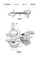
- FIG. 5is one embodiment of the scuffer roller
- FIG. 6is another embodiment of the scuffer roller.
- FIG. 1schematically depicts an electrophotographic printing machine incorporating features of the present invention therein. It will become evident from the following discussion that the features of the present invention are not specifically limited in their application to the particular printing machine depicted herein, but may be used in any suitable printing machine wherein a tray having a scuffer mechanism is employed.
- FIG. 1 of the drawingsthe printing machine and its operation will be described with reference thereto.
- the operation of the printing machinewill be described briefly hereinafter.
- the electrophotographic printing machineis shown reproducing copies of original documents advanced by a document feeder, indicated generally by the referenced numeral 20.
- Document feeder 20is shown positioned above a platen at the imaging station of printing machine 10.
- Document feeder 20provides for automatically feeding or transporting individually registered and spaced documents onto and over the platen 23 of copier 10.
- Document feeder 20has the conventional "racetrack" document loop path configuration, and preferably has generally known inverting and non-inverting return circulation paths to loading and restacking tray 21. Documents may be fed to platen 23 to be copied by the same platen transport belt 24 from either the loading side slot 22 at one side of the document feeder 20, or from the loading or stacking tray 21.
- the regular document feeding inputis from the bottom of the stacking tray 21 through an arcuate, inverting, input path 25 to the upstream end of the platen transport 24.
- This input path 25preferably includes a known stack bottom corrugating feeder-separator belt and and air knife system 26, and a first set of turn baffles and feed rollers to naturally invert the documents once before copying.
- the documentsAfter the documents are copied on platen 23, they may be ejected by the platen transport system 24 into a downstream or off-platen rollers and fed passed a gate or gates and sensors. Depending upon the position of these gates, they either guide the documents directly to a document output path to a catch tray, or more commonly, the documents are deflected into a return path 40 taking them back to tray 21 to restack on top of the documents then in tray 21. In this way, the document set can be continuously refed and recirculated.
- Return path 40includes reversible rollers to provide a choice of two different return paths to tray 21; a simplex return path 44 with one inversion, or a reversible duplex return path 46 without an inversion.
- the duplex return path 46provides a desired inversion of duplex documents in one circulation. In normal operation, a duplex document has only one inversion per circulation. In contrast, in the simplex circulation path there are two inversions per circulation, one in each of the paths.
- electrophotographic printing machine 10includes a belt 13 having a photoconductive surface deposited on a conductive substrate.
- the beltadvances successive portions of the photoconductive surface to various processing stations disposed about the path of movement thereof.
- a corona generating devicecharges the photoconductive surface of the belt to a relatively, high, substantially uniform potential.
- the charged portion of the photoconductive surfaceis advanced through the imaging station.
- a flash lampilluminates the original document on platen 23.
- the light rays reflected from the original documentare transmitted through the lens forming a light image thereof. These light rays are focused onto the charged portion of the photoconductive surface to selectively dissipate the charge thereon.
- the beltadvances it through a development station.
- a magnetic brush development systemtransports a developer material of carrier granules and toner particles into contact with the electrostatic latent image recorded on the photoconductive surface.
- the toner particlesare attracted from the carrier granules to the electrostatic latent image forming a developed image or a toner powder image on the photoconductive surface of the belt.
- the beltadvances the developed image to the transfer station.
- a copy sheetis moved into contact with the toner powder image.
- a corona generating devicesprays ions onto the backside of the copy sheet. This attracts the toner powder image from the photoconductive surface to the copy sheet.
- the copy sheetmoves to the fusing station.
- the fusing stationincludes a fuser assembly which permanently affixes the transferred toner powder image to the copy sheet.
- the fuser assemblyincludes a heated fuser roll and back-up roll. The copy sheet passes between the fuser roll and back-up roll with the toner powder image contacting the fuser roll. In this manner, the toner powder image is permanently affixed to the copy sheet.
- a conveyor beltguides the advancing sheet to a catch tray or to a finishing station wherein a plurality of sets may be formed with the copy sheets being either stapled or bound to one another.
- Blank or clean copy sheetscan be conventionally fed from trays 11 or 12, or the high capacity feeder input thereunder, to transfer station 14 to have the toner powder image transferred thereto.
- the transferred toner powder imageis fused to the copy sheet by fuser 15.
- a duplex tray 16collects and temporarily stacks documents therein which are being duplexed.
- Duplex tray 16has a backstop 50 thereon. Backstop 50 arrests the movement of the sheet being advanced onto duplexed tray 16 and provides registration therefor by moving it into a corner registration guide. Further details of duplex tray 16 and backstop 50 will be discussed hereinafter with reference to FIGS. 2 through 6, inclusive.
- a sheet feeder 52advances the stacked sheets from duplex tray 16 by a path 17 to transfer station 14. At transfer station 14, the sheet receives an image on the second side thereof in the same manner as the image was deposited on the first side thereof.
- the completed duplex copyexits to a finishing and stacking module via output path 18.
- All printing machine document feeder and finishing operationsare preferably controlled by a programmable controller 100.
- a programmable controller 100As suitable known programmable microprocessor system is described in U.S. Pat. No. 4,475,156, the relevant portion thereof being hereby incorporated into the present application.
- the controller 100controls all of the machine functions described herein including all sheet feeding.
- a known touch screen type of operator input control and displayis utilized in conjunction with controller 100.
- Duplex tray 16includes an adjustable copy sheet scuffer or backstop mechanism 50 for engaging the leading edge 54 of the copy sheets 56 to be duplexed as the copy sheets are fed into duplex tray 16 when the printing machine is programmed to produce duplex or two-sided copies.
- the backstop rollers 50are movable toward and away from the bottom feeder 52 in order to position the leading edges of copy sheets in the trays so that they may be properly fed out of the tray by feeder 52 during the duplex operation. The movement of the backstop rollers is sufficient to accommodate the various types of sheet widths that may be usable in the printing machine.
- a plurality of copy sheets 52are positioned in tray 16 with their rear edges 54 against rollers 50.
- a motor and pulley assembly 58drives rollers 50.
- rollers 50are rotated about their longitudinal axes.
- Rollers 50are positioned so that their longitudinal axes are substantially perpendicular to tray 16 and to the stack of sheets 56.
- duplex tray 16with cutouts 60 therein. These cutouts or slots permit rollers 50a and rollers 50b to extend in a direction substantially perpendicular to the planar surface of tray 16 while still being movable relative to the edge of stack 54 so as to be adjustable for different size sheets. Rollers 50a and 50b are driven by a motor 58 coupled to belt 62. Drive belt 62 is entrained about a pulley 64 which rotates a shaft 66 having rollers 50a and 50b mounted respectively thereon.
- Backstop rollers 50a and 50bare spaced from one another and driven by a belt pulley system coupled to motor 58. With this arrangement, the longitudinal axis of rollers 50a and 50b are parallel to each other and to the rear side of tray 16. Motor 58 is mounted upon the upper side of plate 68. Timing belt 62 is arranged to impart rotation to rollers 50a and 50b in the same direction counter clockwise to thereby force or scuff each sheet of paper entering the tray against side registration stops mounted on the side edge of the bottom plate of duplex tray 16.
- the scuffer mechanismis adapted to register sheets in the forward direction and also to produce side registration so that copy sheets leaving the duplex tray for the duplex operation are properly corner registered as they leave the tray.
- backstop roll 50aincludes a sleeve 70 made preferably from an elastomeric material.
- Sleeve or tubular member 70is substantially hollow.
- a drive shaft 72is mounted interiorly of sleeve 70 and spaced from the interior walls thereof.
- Sleeve 70is press fit onto drive shaft 72 at one end. There is a hole in one end of sleeve 70 to permit air to escape during the press fit assembly.
- Sleeve 70is open ended at the other end to permit drive shaft 72 to be mounted therein.
- a bottom cap 74is press fit into sleeve 70 and locates the sleeve concentrically relative to drive shaft 72 by means of a tight tolerance fit with drive shaft 72.
- Drive shaft 72extends outwardly from the bottom cap of sleeve 70 and is mounted on a pulley to be driven by timing belt 62 coupled to motor 58.
- backstop roll 50aincludes a tube 76 having both ends opened.
- a drive shaft 78is mounted interiorly of tube 76 and extends outwardly therefrom at one end.
- Top cap 80receives one end of shaft 78 and encloses and secures that end of tube 76.
- Bottom cap 82secures the other end of tube 76 while permitting shaft 78 to pass therethrough and extend outwardly therefrom.
- the outwardly extending portion of shaft 78has a pulley mounted thereon with timing belt 62 wrapped thereabout so as to be driven by motor 58.
- the backstop rollers depicted in FIGS. 5 and 6are hollow.
- the wall thicknessis designed to be relatively thin and preferably made of an elastomeric material so as to permit the roll sleeve or tube to deflect when the leading edge of the sheet engages it.
- the leading edge of the sheetengages the sleeve or tube of the backstop roller.
- the wall thereofdeflects absorbing energy. This also increases the contact area of the sheet with the roll. As the contact roll increases, the stress on the leading edge of the sheet is reduced.
- the leading edge of the sheetdoes not dent and cause deletions on the copy.
- the embodiment shown in FIG. 5has the inner diameter of sleeve 70 reduced to enable the drive shaft 72 to be press fit therein.
- This featurecan be molded into the part.
- the bottom caphas a center hole with a tight clearance fit to the drive shaft and a sharp edged outer diameter that the sleeve is press fit over.
- the embodiment depicted in FIG. 6consists of a hollow tube with a top and bottom cap.
- the top caphas a narrow diameter that the sleeve is press fit over.
- a set screwattaches the drive shaft to the tube.
- the bottom capis essentially identical to that of the FIG. 5 and has a center hold, with a tight clearance fit to the drive shaft and a sharp edged outer diameter that the tube is press fit over.
- the duplex tray of the present inventionhas a backstop roller positioned therein to engage an edge of the sheets being collected.
- the backstop rollerarrests movement of the sheets and deflects upon being contacted by the sheet edge. In this way, the backstop roller absorbs energy and increases the sheet contact area so as to minimize denting and image delation of the sheet edge during contact.
Landscapes
- Engineering & Computer Science (AREA)
- Mechanical Engineering (AREA)
- Counters In Electrophotography And Two-Sided Copying (AREA)
- Paper Feeding For Electrophotography (AREA)
- Conveyance By Endless Belt Conveyors (AREA)
Abstract
Description
Claims (8)
Priority Applications (2)
| Application Number | Priority Date | Filing Date | Title |
|---|---|---|---|
| US07/840,201US5201425A (en) | 1992-02-24 | 1992-02-24 | Sheet tray with an energy absorbing backstop and scuffer mechanism |
| JP5026872AJPH0672641A (en) | 1992-02-24 | 1993-02-16 | Sheet collecting and feeding-out device |
Applications Claiming Priority (1)
| Application Number | Priority Date | Filing Date | Title |
|---|---|---|---|
| US07/840,201US5201425A (en) | 1992-02-24 | 1992-02-24 | Sheet tray with an energy absorbing backstop and scuffer mechanism |
Publications (1)
| Publication Number | Publication Date |
|---|---|
| US5201425Atrue US5201425A (en) | 1993-04-13 |
Family
ID=25281703
Family Applications (1)
| Application Number | Title | Priority Date | Filing Date |
|---|---|---|---|
| US07/840,201Expired - LifetimeUS5201425A (en) | 1992-02-24 | 1992-02-24 | Sheet tray with an energy absorbing backstop and scuffer mechanism |
Country Status (2)
| Country | Link |
|---|---|
| US (1) | US5201425A (en) |
| JP (1) | JPH0672641A (en) |
Cited By (11)
| Publication number | Priority date | Publication date | Assignee | Title |
|---|---|---|---|---|
| US5626333A (en)* | 1995-01-12 | 1997-05-06 | Sindo Richo Co., Ltd. | Sorter, sheet jogging device, stapling device, and stapling sorter using those devices for copying machine |
| US5887411A (en)* | 1996-12-04 | 1999-03-30 | Privatizer Systems, Inc. | Apparatus and method for positioning a number of non-transparent enclosure sheets in a document security apparatus |
| US5934045A (en)* | 1996-12-04 | 1999-08-10 | Privatizer Systems, Inc. | Method for providing confidentiality to a facsimile transmission having information associated with a first page of the transmission printed on a first enclosure sheet |
| US5937619A (en)* | 1996-12-04 | 1999-08-17 | Privatizer Systems Incorporated | Apparatus and method for sealing an envelope having a first lateral side and a second lateral side in a document security apparatus |
| US5941048A (en)* | 1996-12-04 | 1999-08-24 | Privatizer Systems, Inc | Apparatus and method of sealing an envelope in a document security apparatus |
| US5946889A (en)* | 1996-12-04 | 1999-09-07 | Privatizer Systems, Inc | Apparatus and method for enclosing a confidential sheet between a first enclosure sheet and a second enclosure sheet within a document security apparatus |
| US5956930A (en)* | 1996-12-04 | 1999-09-28 | Privatizer Systems, Inc. | Apparatus and method of forming an envelope in a document security apparatus |
| US5979148A (en)* | 1996-12-04 | 1999-11-09 | Privatizer Systems, Inc. | Apparatus and method for sealing an envelope in a document security apparatus having a sealing roller with a sealing ridge attached thereto |
| US5996317A (en)* | 1996-12-04 | 1999-12-07 | Privatizer Systems, Inc. | Method for providing confidentiality to a facsimile transmission having a non-printed back enclosure sheet |
| US6076336A (en)* | 1996-12-04 | 2000-06-20 | Privatizer Systems, Inc. | Apparatus and method for advancing a confidential sheet into a pocket defined by a number of enclosure sheets |
| US20040217544A1 (en)* | 2003-04-30 | 2004-11-04 | Prim Hall Enterprises Inc. | Systems, devices, and methods for feeding sheet material to a disk separator |
Citations (11)
| Publication number | Priority date | Publication date | Assignee | Title |
|---|---|---|---|---|
| US2761682A (en)* | 1951-06-15 | 1956-09-04 | Buccicone Dario | Piler stop mechanism |
| US2821391A (en)* | 1955-12-13 | 1958-01-28 | Bucciconi Engineering Company | Bumper pad for sheet piling mechanism |
| CA648541A (en)* | 1962-09-11 | Lamb Grays Harbor Co. | Spring loaded pivoted forward stop for paper stacking mechanism | |
| US4330197A (en)* | 1979-07-16 | 1982-05-18 | Xerox Corporation | Recirculating documents duplex copier |
| US4380332A (en)* | 1981-03-13 | 1983-04-19 | Stone Container Corporation | Snubbing device for blank conveyor apparatus |
| JPS5964470A (en)* | 1982-09-29 | 1984-04-12 | Toshiba Corp | Storing apparatus for business forms |
| JPS63134465A (en)* | 1986-11-21 | 1988-06-07 | Fuji Photo Film Co Ltd | Sheet stacker |
| US4778170A (en)* | 1982-11-22 | 1988-10-18 | Xerox Corporation | Copy sheet tray with adjustable back stop and scuffer mechanism |
| US4883265A (en)* | 1985-03-15 | 1989-11-28 | Canon Kabushiki Kaisha | Tray apparatus |
| US5022640A (en)* | 1985-10-28 | 1991-06-11 | Xerox Corporation | Auto-duplex/simplex feeder module |
| US5116036A (en)* | 1991-03-11 | 1992-05-26 | Eastman Kodak Company | Device for facilitating stacking of sheets in a hopper |
- 1992
- 1992-02-24USUS07/840,201patent/US5201425A/ennot_activeExpired - Lifetime
- 1993
- 1993-02-16JPJP5026872Apatent/JPH0672641A/enactivePending
Patent Citations (11)
| Publication number | Priority date | Publication date | Assignee | Title |
|---|---|---|---|---|
| CA648541A (en)* | 1962-09-11 | Lamb Grays Harbor Co. | Spring loaded pivoted forward stop for paper stacking mechanism | |
| US2761682A (en)* | 1951-06-15 | 1956-09-04 | Buccicone Dario | Piler stop mechanism |
| US2821391A (en)* | 1955-12-13 | 1958-01-28 | Bucciconi Engineering Company | Bumper pad for sheet piling mechanism |
| US4330197A (en)* | 1979-07-16 | 1982-05-18 | Xerox Corporation | Recirculating documents duplex copier |
| US4380332A (en)* | 1981-03-13 | 1983-04-19 | Stone Container Corporation | Snubbing device for blank conveyor apparatus |
| JPS5964470A (en)* | 1982-09-29 | 1984-04-12 | Toshiba Corp | Storing apparatus for business forms |
| US4778170A (en)* | 1982-11-22 | 1988-10-18 | Xerox Corporation | Copy sheet tray with adjustable back stop and scuffer mechanism |
| US4883265A (en)* | 1985-03-15 | 1989-11-28 | Canon Kabushiki Kaisha | Tray apparatus |
| US5022640A (en)* | 1985-10-28 | 1991-06-11 | Xerox Corporation | Auto-duplex/simplex feeder module |
| JPS63134465A (en)* | 1986-11-21 | 1988-06-07 | Fuji Photo Film Co Ltd | Sheet stacker |
| US5116036A (en)* | 1991-03-11 | 1992-05-26 | Eastman Kodak Company | Device for facilitating stacking of sheets in a hopper |
Cited By (12)
| Publication number | Priority date | Publication date | Assignee | Title |
|---|---|---|---|---|
| US5626333A (en)* | 1995-01-12 | 1997-05-06 | Sindo Richo Co., Ltd. | Sorter, sheet jogging device, stapling device, and stapling sorter using those devices for copying machine |
| US5887411A (en)* | 1996-12-04 | 1999-03-30 | Privatizer Systems, Inc. | Apparatus and method for positioning a number of non-transparent enclosure sheets in a document security apparatus |
| US5934045A (en)* | 1996-12-04 | 1999-08-10 | Privatizer Systems, Inc. | Method for providing confidentiality to a facsimile transmission having information associated with a first page of the transmission printed on a first enclosure sheet |
| US5937619A (en)* | 1996-12-04 | 1999-08-17 | Privatizer Systems Incorporated | Apparatus and method for sealing an envelope having a first lateral side and a second lateral side in a document security apparatus |
| US5941048A (en)* | 1996-12-04 | 1999-08-24 | Privatizer Systems, Inc | Apparatus and method of sealing an envelope in a document security apparatus |
| US5946889A (en)* | 1996-12-04 | 1999-09-07 | Privatizer Systems, Inc | Apparatus and method for enclosing a confidential sheet between a first enclosure sheet and a second enclosure sheet within a document security apparatus |
| US5956930A (en)* | 1996-12-04 | 1999-09-28 | Privatizer Systems, Inc. | Apparatus and method of forming an envelope in a document security apparatus |
| US5979148A (en)* | 1996-12-04 | 1999-11-09 | Privatizer Systems, Inc. | Apparatus and method for sealing an envelope in a document security apparatus having a sealing roller with a sealing ridge attached thereto |
| US5996317A (en)* | 1996-12-04 | 1999-12-07 | Privatizer Systems, Inc. | Method for providing confidentiality to a facsimile transmission having a non-printed back enclosure sheet |
| US6076336A (en)* | 1996-12-04 | 2000-06-20 | Privatizer Systems, Inc. | Apparatus and method for advancing a confidential sheet into a pocket defined by a number of enclosure sheets |
| US20040217544A1 (en)* | 2003-04-30 | 2004-11-04 | Prim Hall Enterprises Inc. | Systems, devices, and methods for feeding sheet material to a disk separator |
| US7014184B2 (en)* | 2003-04-30 | 2006-03-21 | Prim Hall Enterprises Inc. | Systems, devices, and methods for feeding sheet material to a disk separator |
Also Published As
| Publication number | Publication date |
|---|---|
| JPH0672641A (en) | 1994-03-15 |
Similar Documents
| Publication | Publication Date | Title |
|---|---|---|
| US3719266A (en) | Sheet stacking apparatus | |
| US5288062A (en) | High capacity compiler with vertically adjustable sheet discharge and acquire means | |
| CA1039678A (en) | Self-actuating sheet reverser | |
| US5473419A (en) | Image forming apparatus having a duplex path with an inverter | |
| US4359217A (en) | Inverter with proportional force paper drive | |
| US4744555A (en) | Sheet transport and registration apparatus | |
| CA1076058A (en) | Sheet turn around/inverter | |
| CA1038322A (en) | Sheet reversing mechanism | |
| EP0099250B2 (en) | Improvements in sheet stackers | |
| US5720478A (en) | Gateless duplex inverter | |
| US4778170A (en) | Copy sheet tray with adjustable back stop and scuffer mechanism | |
| JPH06604B2 (en) | Sheet rotation device in copy machine | |
| US5201425A (en) | Sheet tray with an energy absorbing backstop and scuffer mechanism | |
| US4487407A (en) | Trail edge copy registration system | |
| US4364550A (en) | Corrugation venturi paper feeder | |
| US4905984A (en) | Set transport | |
| US4832330A (en) | Copy finishing apparatus | |
| USRE33843E (en) | Sheet transport and registration apparatus | |
| EP0378005B1 (en) | Copy sheet de-registration device | |
| EP0122992B1 (en) | Sheet collecting apparatus | |
| US5156392A (en) | Moving edge side registration device | |
| US4938468A (en) | Non-rotating paper path idler | |
| GB2126997A (en) | Producing registered sets of copy sheets | |
| GB2126998A (en) | Changing direction of a jet of sheets | |
| JPS6113227B2 (en) |
Legal Events
| Date | Code | Title | Description |
|---|---|---|---|
| AS | Assignment | Owner name:XEROX CORPORATION, A NY CORP., CONNECTICUT Free format text:ASSIGNMENT OF ASSIGNORS INTEREST.;ASSIGNORS:ROUX, MARY A.;RATHBUN, THOMAS W.;DEMCHOCK, STEPHEN A.;REEL/FRAME:006077/0559 Effective date:19920220 | |
| STCF | Information on status: patent grant | Free format text:PATENTED CASE | |
| FEPP | Fee payment procedure | Free format text:PAYOR NUMBER ASSIGNED (ORIGINAL EVENT CODE: ASPN); ENTITY STATUS OF PATENT OWNER: LARGE ENTITY | |
| FPAY | Fee payment | Year of fee payment:4 | |
| FPAY | Fee payment | Year of fee payment:8 | |
| AS | Assignment | Owner name:BANK ONE, NA, AS ADMINISTRATIVE AGENT, ILLINOIS Free format text:SECURITY INTEREST;ASSIGNOR:XEROX CORPORATION;REEL/FRAME:013153/0001 Effective date:20020621 | |
| AS | Assignment | Owner name:JPMORGAN CHASE BANK, AS COLLATERAL AGENT, TEXAS Free format text:SECURITY AGREEMENT;ASSIGNOR:XEROX CORPORATION;REEL/FRAME:015134/0476 Effective date:20030625 Owner name:JPMORGAN CHASE BANK, AS COLLATERAL AGENT,TEXAS Free format text:SECURITY AGREEMENT;ASSIGNOR:XEROX CORPORATION;REEL/FRAME:015134/0476 Effective date:20030625 | |
| FPAY | Fee payment | Year of fee payment:12 | |
| AS | Assignment | Owner name:XEROX CORPORATION, CONNECTICUT Free format text:RELEASE BY SECURED PARTY;ASSIGNOR:JPMORGAN CHASE BANK, N.A. AS SUCCESSOR-IN-INTEREST ADMINISTRATIVE AGENT AND COLLATERAL AGENT TO JPMORGAN CHASE BANK;REEL/FRAME:066728/0193 Effective date:20220822 |