US5201212A - Line leak detector and method - Google Patents
Line leak detector and methodDownload PDFInfo
- Publication number
- US5201212A US5201212AUS07/840,720US84072093AUS5201212AUS 5201212 AUS5201212 AUS 5201212AUS 84072093 AUS84072093 AUS 84072093AUS 5201212 AUS5201212 AUS 5201212A
- Authority
- US
- United States
- Prior art keywords
- line
- test
- reservoir
- leak rate
- pressure
- Prior art date
- Legal status (The legal status is an assumption and is not a legal conclusion. Google has not performed a legal analysis and makes no representation as to the accuracy of the status listed.)
- Expired - Fee Related
Links
Images


Classifications
- G—PHYSICS
- G01—MEASURING; TESTING
- G01M—TESTING STATIC OR DYNAMIC BALANCE OF MACHINES OR STRUCTURES; TESTING OF STRUCTURES OR APPARATUS, NOT OTHERWISE PROVIDED FOR
- G01M3/00—Investigating fluid-tightness of structures
- G01M3/02—Investigating fluid-tightness of structures by using fluid or vacuum
- G01M3/26—Investigating fluid-tightness of structures by using fluid or vacuum by measuring rate of loss or gain of fluid, e.g. by pressure-responsive devices, by flow detectors
- G01M3/28—Investigating fluid-tightness of structures by using fluid or vacuum by measuring rate of loss or gain of fluid, e.g. by pressure-responsive devices, by flow detectors for pipes, cables or tubes; for pipe joints or seals; for valves ; for welds
- G01M3/2892—Investigating fluid-tightness of structures by using fluid or vacuum by measuring rate of loss or gain of fluid, e.g. by pressure-responsive devices, by flow detectors for pipes, cables or tubes; for pipe joints or seals; for valves ; for welds for underground fuel dispensing systems
Definitions
- This inventionpertains generally to an apparatus and method for detecting leaks in underground supply lines for gasoline and other hydrocarbon fuels. More specifically, the invention pertains to detecting leaks in a supply line between a fuel pump and an underground reservoir containing gasoline at a gasoline service station.
- Each service stationis essentially a self-contained gasoline dispensing unit. While large pipeline networks are employed in petroleum production fields to connect various units of the field to a central distribution point, the same is not true in the distribution of refined petroleum to service stations.
- Each service stationtypically has one or more reservoirs buried under the ground for storing gasoline that are periodically resupplied with gasoline trucked in from various locations.
- the fuelis pumped from the storage tank to the dispenser by a submersible pump which is activated when the dispenser switch is turned on and deactivated at the end of the dispensing operation.
- a check valveis incorporated in the pump assembly so that at the end of a dispensing cycle, the product line retains the fuel that has been pumped into it, thus permitting the gasoline to be delivered immediately at the start of the next dispensing cycle.
- a pressure relief valve built into the pump assemblyis used to relieve the product line pressure to a level of 11-15 psi following the end of each dispensing cycle. Because of the positive pressure that is maintained in the product line, any leaks in the piping between the check valve and the dispenser can result in significant amounts of fuel leaking from the product line and contaminating the subsoil and groundwater.
- the lineshave therefore become a source of concern for many environmentalists.
- the primary concernarises from the potential for contamination of underground water supplies caused by leaking gasoline or other refined petroleum products.
- governmental authoritieshave imposed strict controls on the operation of such underground reservoirs to prevent contamination and to help arrest the deteriorating state of the environment.
- the test equipment and method now in useinvolves a pressurized reservoir that is graduated for volumetric measurement.
- the pressurized reservoiris connected to the line under test which is then pressurized. After the line is pressurized, the reservoir is monitored for fluid loss into the line. Vapor pockets sometimes form in the line under test but are normally removed by repeatedly pressurizing and depressurizing the line until the vapor collects at one end of the line whereupon it is bled off.
- This system and method of testingis adversely impacted by volumetric changes caused by temperature variations in the line, the difficultly in accurate determination of volumetric change in the reservoir, human error in operator measurements and calculations, and the operator's exercise of judgment at the end of the test.
- U.S. Pat. No. 4,876,530is directed to a method and apparatus for detecting leakage from underground fuel tanks and also from the pressurized lines which deliver the fuel to the dispensers.
- the specification of that patentdescribes the use of "special measures" which are said to be taken to distinguish thermal contraction from an actual leak in the line which rely upon "the physical fact that the pressure of volume decay caused by thermal contraction decreases with time, whereas the volume decay caused by a leak does not.”
- the method described thereinisolates the line(s) under test from the rest of the product storage and delivery system, introducing a number of variables into the line leak test which decrease the reliability and precision of the test.
- no accurate, reliable, and simple leak test for just the linesis available, and there is a need for such a test for both environmental reasons and in light of the above-described, exacting governmental regulations.
- the inventioncomprises an apparatus and a method for testing the leakage rate of fluid from a liquid fluid containing line such as the line between the liquid containing underground reservoir of a gasoline service station and the impact valve to which the line is connected.
- the apparatuscomprises an instrument package modified to include (a) a differential pressure transducer mounted to a reservoir for indicating volumetric change in the reservoir; (b) a temperature transducer mounted in the reservoir for monitoring temperature fluctuation in the reservoir; (c) a gauge pressure transducer mounted in the reservoir; (d) a remote temperature sensor; and (e) a data acquisition and processing system.
- the methodcomprises the steps of connecting the apparatus to the line under test, isolating the line from the impact valve and underground reservoir, and pressurizing the fluid in the isolated line having the test apparatus connected thereto.
- the test systemthen monitors volumetric change in the reservoir as well as pressure and temperature fluctuations in the system and line under test at preselected time intervals. At the end of a predetermined test period, the system calculates the leak rate during each five minute interval of the test as well as a cumulative leak rate. Fluctuations and trends in the leak rate data during the test are examined against preselected criteria of change to determine whether the calculated cumulative leak rate is an accurate measurement of the actual rate of leakage of the liquid fluid from the fluid filled line.
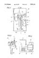
- FIG. 1is an illustration of the apparatus of the invention as set up and employed for use in testing.
- FIG. 2is a more detailed depiction of the instrument package of the apparatus in FIG. 1.
- FIG. 3is a perspective view of a portion of the submersible pump as it is depicted in FIG. 1 with an isolation plug installed.
- FIG. 4is an enlarged depiction of the computational package of the apparatus as viewed from the top and as depicted in FIG. 1.
- FIG. 5is a schematic diagram of the temperature data and acquisition circuitry housed in the instrumentation package of FIG. 2.
- FIG. 6A and 6Bare a schematic diagram of the data processing, analog-to-digital converting, and input/output circuitry of the computational package of FIG. 4.
- FIG. 7is a schematic diagram of the keypad and associated connectors of the computational package of FIG. 4.
- FIG. 8a and 8bare schematic diagrams of the power circuits of the computational package of FIG. 4.
- FIG. 9is flow chart summarizing selected steps of a presently preferred embodiment of the method of the present invention.
- FIG. 1illustrates the invention as it is employed to test an underground line.
- Line 10, reservoir 14, submersible pump 30, impact valve 17, and dispensing pump 12are all standard equipment commonly found installed at gasoline service stations as is shown.
- Isolation plug 35, instrument package 20, computational package 40, and lines 11, 13, and 16 in the preferred embodimentare transported to different service stations by truck 18 and assembled for testing.
- the apparatus of the inventionin its preferred embodiment comprises instrument package 20, line 11, line 13, computational package 40 and line 16.
- Instrument package 20is connected to line 10 when line 10 is under test via line 11 and through isolation plug 35 (see FIG. 3) installed in submersible pump 30.
- Submersible pump 30normally pumps gasoline from underground reservoir 14 to dispensing pump 12 via line 10 and impact valve 17 but instead isolates line 10 from reservoir 14 when modified using isolation plug 35.
- Instrument package 20is further connected to computational package 40 via line 13 and to a pressurized source of nitrogen aboard truck 18 through line 16.
- FIG. 2illustrates instrument package 20 of the presently preferred embodiment shown in FIG. 1 in greater detail.
- Instrument package 20is a modification of a prior art device constructed and used by Tanknology Corporation International of Houston, Tex.
- the prior art devicehas been adapted by the addition of temperature transducer 26, gauge pressure transducer 60, differential pressure transducer 62, remote temperature sensor 52, and signal processing system 100, the latter three being located beneath cover 28 and all being shown schematically in FIG. 5.
- Temperature transducer 26 in the preferred embodimentis a standard thermistor or thermocouple, as is remote temperature sensor 52, that is connected to instrument package 20 and jack 50 by plug 38 through cable 54 for a purpose to be described below.
- Gauge pressure transducer 60is used to measure the pressure exerted on the fluid by the inert gas, the pressure being measured relative to atmospheric pressure.
- Differential pressure transducer 62is used to determine the mass of fluid captured in a test reservoir, or graduated cylinder, 32 as more fully described below by measuring the differences in pressure between the top and bottom of cylinder 32.
- Differential pressure transducer 62may be any one of several commercially available transducers. For example, model SCX01D (Sensym, Inc., Sunnyvale, Calif.), 10 PC series (Microswitch Division of Honeywell, Inc., Freeport, Ill.) and P3061-20 WD (Lucas Schaevitz, Inc., Pennsauken, N.J.) transducers have all been used to varying degrees of advantage, the latter representing the presently preferred transducer.
- the Microswitch transduceris sensitive to common mode pressure, e.g., output changes over the range of the pressure differential, such that the output from pressure transducer 60 must be used to correct the output from that particular transducer 62.
- the central component of instrument package 20is the test reservoir, which in the preferred embodiment is graduated cylinder 32.
- the content of graduated cylinder 32is controlled by filling with liquid fluid contained in holding tank 22 through line 21 when filler valve 34 is opened.
- the contentis also controlled by injecting nitrogen or some other suitable gas into cylinder 32 from a pressurized source via quick-connector 27, valve 25, and line 33. In addition to nitrogen, any inert gas that is non-flammable is also suitable.
- Pressure exerted by the contents of cylinder 32is controlled by monitoring gauge 24 and by bleeding gas through relief valve 23 in line 33.
- Outlet valves 29a-bare used to drain the liquid content of cylinder 32.
- Outlet valve 29ais a one-quarter inch outlet valve with a quick disconnect and outlet valve 29b is a one-half inch outlet valve with a quick disconnect, both as are well known in the art.
- FIG. 3illustrates submersible pump 30 having the isolation plug 35 installed therein.
- Line 10is isolated from underground reservoir 14 by the installation of isolation plug 35 in submersible pump 30 and is consequently placed in fluid flow communication with line 11.
- isolation plugs and their useare commonly known among those skilled in the art.
- Instrumentation package 20 of FIGS. 1-2is connected to isolation plug 35 via line 11.
- Isolation plug 35requires either quarter-inch or half-inch connectors on line and thus the necessity for having both outlet valve 29a and b on instrumentation package 20.
- modifying submersible pump 30 with isolation plug 35isolates line 10 and places it in fluid flow communication with line 11.
- Impact valve 17 shown in FIG. 1is designed to shut off excessive fluid flow through line 10 during normal operation to prevent large gasoline spills that may occur if dispensing pump 12 is damaged or malfunctions. Valves such as impact valve 17 are required by federal regulations for each pump such as dispensing pump 12. As is well known in the art, impact valve 17 also has a manual switch that will also block fluid flow when appropriately set in order to perform routine maintenance and inspection of dispensing pump 12. Impact valve 17 is used in this manner to isolate line 10 from dispensing pump 12. Line 10 is therefore isolated from both underground reservoir 14 and dispensing pump 12 for testing purposes.
- Computational package 40 of FIG. 1is illustrated in greater detail in FIG. 4.
- Computational package 40 in its preferred embodimentis a formed aluminum case manufactured for housing instrumentation.
- the case of computational package 40includes several electrical circuits depicted schematically in FIGS. 6A-B with some interactive components mounted on the top and whose schematic is shown in FIG. 7.
- the operatorenters and receives test control data with computational package 40 using display 45, keypad 48, and printer 42.
- display 45is a liquid crystal display displaying two lines of twenty (20) characters each
- keypad 48is a 16 key, 4 ⁇ 4 matrix unit
- printer 42is a standard 40 column dot-matrix printer.
- Keypad 48communicates with micro-controller 72 of FIG. 6A via connectors 78 and 80 of FIG. 6A and connector 82 of FIG. 7.
- Keypad 48further communicates with printer 42 via connector 84 of FIG. 7.
- Computational package 40also includes power on-off switch 46 (FIGS. 4 and 8A) and reset button 44 (FIG. 6A).
- Computational package 40interfaces with and receives multiplexed analog data in parallel from the signal processing system 100 of instrument package 20 via line 13 and connector 66.
- Signal processing system 100is located under cover 28 of instrument package 20 in FIGS. 1-2 and is a data acquisition and signal transmitting system as depicted schematically in FIG. 5.
- System 100translates the output of temperature transducer 26, remote temperature transducer 52, differential pressure transducer 62, and gauge pressure transducer 60 to a voltage between 0-5 volts for transmission to computational package 40 (FIG. 4).
- Signal conditioningis accomplished with integrated circuit operational amplifiers in signal processing system 100 in any one of several common circuit designs for acquisition and transmission of data. All testing and data processing is performed in accordance with software stored in a 64 Kbit EPROM 74 and run using 8-bit micro-controller 72 which is an 8052AHBASIC processor produced by Intel Corporation (Santa Clara, Calif.).
- 8-bit micro-controller 72which is an 8052AHBASIC processor produced by Intel Corporation (Santa Clara, Calif.).
- the use of the above-described Lucas Schaevitz pressure transducer as the differential pressure transducer 62permits a resolution of ten (10) bits with minimal hardware or software changes.
- A/D convertor 70can be either an 8-bit or 10-bit converter depending upon the resolution of associated transducers.
- the differential transducer 62produced by Lucas Schaevitz, which has self-contained signal conditioning circuitry is utilized, the signal conditioning circuitry shown in FIG. 5 associated with differential transducer 62 can be omitted.
- Datais received by computational package 40 from instrument package 20 via line 13 and connector 66 is multiplexed by multiplexor 68, converted to digital form by A/D converter 70. Both are stored in 64-Kbit RAM 76 and contemporaneously printed during testing by printer 42 which also prints the results of the testing once testing is completed.
- Micro-controller 72communicates with the other integrated circuit chips in FIGS. 6A-B via three buses, each bus being dedicated for one of control, data, or address signals, respectively. For the sake of clarity, these buses are not depicted in their entirety but are simply labeled as such on the appropriate leads to the individual chips.
- Computational package 40is powered by, a 12 volt dc gell-cell battery 90 (shown in FIG. 8A) of a type produced by any of several manufacturers.
- the 12 volt signalis reduced to 5 volts by voltage limiter 92, and both 9 and 12 volt signal and a +5 volt signal are transmitted to other components via connector 94.
- the battery supply of battery 90is capable of powering all electrical components of instrument package 20 via line 13 as well as those of computational package 40 for an entire day. Further, the battery supply can be recharged from the electrical system of truck 18 via a jack in the side of computational package 40 that is also not shown.
- Separate +12 volt and +5 volt signalsare generated by the circuit depicted schematically in FIG. 8B for the purpose of producing a clean, independently generated reference signal for A/D converter 70 in FIG. 6 and transmitted by connector 96.
- test unitcomprised of instrumentation package 20 and computation package 40 is set up in the configuration illustrated in FIG. 1 and as previously described herein except that the test unit is not yet connected to line 10 or submersible pump 30. Selected steps in the subsequently described method of the invention are summarized in the flow chart of FIG. 9.
- test system parametersinclude the diameter and length of line 10, the type of product contained in line 10 (which should be the same as that in underground reservoir 14), and the period of time over which the test will be conducted. This is done using keypad 48 and display 45 of computational unit 40.
- Computational package 40then calculates the standard line volume of the line under test (line 10) and the cubic thermal expansion rate for the product contained in underground reservoir 14 in calculations during the test from the entered information (step 102).
- Holding tank 22 of instrumentation package 20 shown in FIG. 2must be filled with the same type of fluid as that stored in underground reservoir 14.
- a convenient way to obtain filling fluidis to obtain a small amount of fluid from reservoir 14 via dispensing pump 12, line 10 and submersible pump 30.
- Obtaining the fluid in this manneralso has the advantage of ensuring that the line 10 is relatively full of fluid, thereby reducing the amount of vapor in line 10; even so, line 10 is likely to contain enough vapor to affect the test such that further reductions in the amount of vapor present in the line 10 as described below is beneficial. Also, it is because of the presence of the vapor in line 10 that line 10 is referred to herein as liquid fluid containing line. If the filling fluid from holding tank 22 is obtained in this manner, it must be done before line 10 is isolated from underground reservoir 14 and dispensing pump 12.
- the temperature of the product in line 10is measured (step 104) before testing regardless of whether fluid is obtained for holding tank 22 as described above.
- the temperatureis measured before line 10 is isolated from either dispensing pump 12 or reservoir 14.
- remote temperature sensor 52is inserted into line 10 through the aperture in submersible pump 30 into which isolation plug 35 is fitted (shown in FIG. 3) when line 10 is isolated from reservoir 14 whereupon the temperature is taken and recorded. Once the temperature is taken, remote temperature sensor 52 is removed. If fluid is obtained for holding tank 22 in the manner described above, the temperature of the product in line 10 may alternatively be taken by simply inserting remote temperature sensor 52 into the product received through dispensing pump 12.
- line 10Since line 10 is the line to be tested for leaks, it must be isolated from the remainder of the pumping dispensing system (step 106). This is accomplished by manually closing impact valve 17 and modifying submersible pump 30 with isolation plug 35 as heretofore described. Line 10 must be filled with fluid to as great an extent as is practically possible during testing since air pockets or other gaseous deposits adversely impact the results of the test.
- instrumentation package 20is then placed in fluid flow communication with line 10 via line 11 and isolation plug 35. Instrumentation package 20 is then used to pressurize and depressurize the content of line 10 to cause vapor pockets to coalesce at either end of line 10 where they are bled off in order to remove any such gaseous pockets as is well known in the art.
- test reservoir 32is again filled and placed under 50 psi using nitrogen. In the event of over-pressurization, pressure is bled using relief valve 23. The system is then ready for testing.
- step 110testing is begun and is actually conducted by software stored in data processing circuitry housed in computational package 40 (step 110) as more fully described below.
- Pressure and temperature dataare collected by differential pressure transducer located under cover 28, temperature transducer 26, gauge pressure transducer located under cover 28 and remote temperature sensor 52, and transmitted by signal processing system 28 from instrumentation package 20 to computational package 40 through line 13.
- the pressure exerted by the fluid in the reservoir, the pressure at the top of the reservoir, and the temperature of the fluid in the reservoirare sampled every thirty seconds (step 112) for the duration of the test and permanently recorded with printer 42.
- This datais also stored in (step 114) random access memory 76 in computational package 40.
- Typical test runs in the preferred embodimentare of thirty or sixty minutes, but test runs may be of different durations.
- the systemreads the data at thirty second intervals and logs it to printer 42.
- step 116the temperature of the product in the line is then measured again using the remote temperature sensor 52. Once the post-test temperature is taken, the software then calculates the volumetric change in the fluid in test reservoir 32 and in line 10 due to temperature fluctuations as determined from post-test and pre-test readings. This volumetric change due to temperature is then used to correct the overall measured change in volume of the total amount of fluid found in both reservoir 32 and line 10 (step 118).
- line 10was completely fluid filled when testing began and any fluid loss is the result of leakage of liquid fluid from the sealed test system, and is reflected in the change in fluid level in test reservoir 32.
- Total volumetric changecan therefore be derived from the height of fluid in test reservoir 32.
- the current inventioncalculates the column height as measured by the differential pressure transducer of fluid in graduated cylinder/test reservoir 32 at any given time during the test procedure from the weight of the column of fluid in test reservoir 32.
- the weightis determined by the difference in pressures exerted by the fluid in test reservoir 3 at the top of the column and at the bottom as measured by differential pressure transducer 62.
- the weight of the fluidis then calculated from the differential pressure with the product's particular specific gravity in accordance with the known formula.
- the micro-controller of computational package 40calculates the algebraic sum of all the measured volumetric changes and converts that sum to a cumulative leak rate measured in gallons per hour.
- the leak rate for each five minute period of the testis also calculated (step 120) and the standard deviation of the leak rate for each such period is divided by the average leak rate of all the five minute periods to obtain an arbitrary comparison value for each five minute period.
- Each of these valuesis logged by printer 42.
- the micro-controller of computational package 40therefore outputs not only data indicating the overall or cumulative performance of the system under test, but also information broken down into five minute "trending" periods.
- the validity of the measured cumulative leak rateis determined by analyzing the trending information (step 122) to ascertain whether the trending information meets preselected criteria of change. If the trending information is erratic or shows that the leak rate has not leveled off, then the measured cumulative leak rate from that particular test is suspect and the testing should be conducted again (step 124).
- the preselected criterium in the preferred embodimentis operator selectable to accommodate the demands of the customer while complying with governmental regulatory requirements. For instance, when conducting the method for a customer in the United States who wishes to comply with minimal governmental requirements (i.e., maximum leak rate of 0.1 gallons per hour) one might specify a cumulative leak rate of not more than 0.00825 gallons over two successive five minute intervals. However, if the calculated leak rates are trending to zero or are otherwise decreasing, then it is generally appropriate to assume that no leak exists and that the calculated leak rates are the result of electronic noise in the system.
- the preferred embodiment of the inventionalso contemplates using a sound alarm although it is not necessary to the practice of the invention.
- the alarmsounds when either there is an insufficient amount of liquid fluid in test reservoir/graduated cylinder 32 to continue the test or when the test is over.
- circuitryis provided to monitor pressure data, received from instrument package 20, to insure that the liquid fluid level is above a preselected, minimum threshold level and sounds an alarm if it is not.
- the alarmis simply sounded at the end of the test.
Landscapes
- Physics & Mathematics (AREA)
- General Physics & Mathematics (AREA)
- Examining Or Testing Airtightness (AREA)
Abstract
Description
Claims (16)
Priority Applications (1)
| Application Number | Priority Date | Filing Date | Title |
|---|---|---|---|
| US07/840,720US5201212A (en) | 1991-02-13 | 1993-02-21 | Line leak detector and method |
Applications Claiming Priority (2)
| Application Number | Priority Date | Filing Date | Title |
|---|---|---|---|
| US65493991A | 1991-02-13 | 1991-02-13 | |
| US07/840,720US5201212A (en) | 1991-02-13 | 1993-02-21 | Line leak detector and method |
Related Parent Applications (1)
| Application Number | Title | Priority Date | Filing Date |
|---|---|---|---|
| US65493991AContinuation-In-Part | 1991-02-13 | 1991-02-13 |
Publications (1)
| Publication Number | Publication Date |
|---|---|
| US5201212Atrue US5201212A (en) | 1993-04-13 |
Family
ID=27096851
Family Applications (1)
| Application Number | Title | Priority Date | Filing Date |
|---|---|---|---|
| US07/840,720Expired - Fee RelatedUS5201212A (en) | 1991-02-13 | 1993-02-21 | Line leak detector and method |
Country Status (1)
| Country | Link |
|---|---|
| US (1) | US5201212A (en) |
Cited By (46)
| Publication number | Priority date | Publication date | Assignee | Title |
|---|---|---|---|---|
| US5317899A (en)* | 1992-12-11 | 1994-06-07 | Control Engineers, Inc. | Method for detecting leaks in underground product lines |
| US5372032A (en)* | 1993-04-23 | 1994-12-13 | Filippi; Ernest A. | Pressurized piping line leak detector |
| US5421105A (en)* | 1993-12-23 | 1995-06-06 | Schulte; Frank | Dredging system |
| US5440918A (en)* | 1994-04-18 | 1995-08-15 | Oster; Earl H. | Portable piping-and-pump-system testing apparatus |
| US5502435A (en)* | 1994-04-06 | 1996-03-26 | Ralston; Douglas E. | Method and system for monitoring circuit breaker gas pressure |
| US5526679A (en)* | 1995-01-05 | 1996-06-18 | Campo/Miller | Automatically calibrated pressurized piping leak detector |
| US5557965A (en)* | 1994-10-20 | 1996-09-24 | Dover Corporation | Pipeline leak detector |
| US5610323A (en)* | 1995-03-22 | 1997-03-11 | British Gas Plc | Method of testing pipes for leakage |
| US5763764A (en)* | 1995-01-06 | 1998-06-09 | Snap-On Technologies, Inc. | Evaporative emission tester |
| US5763794A (en)* | 1997-01-28 | 1998-06-09 | Texaco Inc. | Methods for optimizing sampling of a petroleum pipeline |
| US5918268A (en)* | 1995-07-07 | 1999-06-29 | Intelligent Controls, Inc. | Line leak detection |
| US5948969A (en)* | 1997-10-20 | 1999-09-07 | Vista Research, Inc. | Methods for measuring the flow rate due to a leak in a pressurized pipe system |
| US6070453A (en)* | 1998-08-12 | 2000-06-06 | Tokheim Corporation | Computerized dispenser tester |
| WO2000042408A1 (en)* | 1999-01-18 | 2000-07-20 | Net, S.A. | Method for detecting mass transfer and/or checking sealing in storage and/or fluid transport facilities |
| FR2803034A1 (en)* | 1999-12-28 | 2001-06-29 | Gerard Fontan | Verifying impermeability of underground liquefied gas storage cavern uses measurements of pressure, volume and temperature |
| US6349601B1 (en) | 1999-06-10 | 2002-02-26 | United Air Lines, Inc. | Aircraft pneumatic system test cart |
| US6389881B1 (en)* | 1999-05-27 | 2002-05-21 | Acoustic Systems, Inc. | Method and apparatus for pattern match filtering for real time acoustic pipeline leak detection and location |
| US20020120411A1 (en)* | 2000-05-02 | 2002-08-29 | Fierro Michael R. | Methods for detecting leaks in pressurized piping with a pressure measurement system |
| USD470064S1 (en) | 2002-07-08 | 2003-02-11 | James C. Yoncuski | Pressure checking apparatus for swimming pool |
| US20040173007A1 (en)* | 2003-03-06 | 2004-09-09 | Mccoy Fred Grant | Method and apparatus for detecting a gas |
| US20040221642A1 (en)* | 2003-03-06 | 2004-11-11 | Cincinnati Test Systems, Inc. | Method and apparatus for detecting leaks |
| US20050005683A1 (en)* | 2003-07-07 | 2005-01-13 | Mass Technology, Inc. | Method and apparatus for storage tank leak detection |
| US20050109082A1 (en)* | 2003-11-20 | 2005-05-26 | Stewart Jack D. | Method for testing parts for leaks |
| EP1537398A1 (en)* | 2002-09-10 | 2005-06-08 | Cegelec Anlagen- und Automatisierungstechnik GmbH & Co KG | Leakage detecting method for pipes and pipe systems |
| WO2006016931A1 (en)* | 2004-07-07 | 2006-02-16 | Mass Technology, Inc. | Method and apparatus for storage tank leak detection |
| US20060090546A1 (en)* | 2004-06-18 | 2006-05-04 | Mccoy Fred G | Method and apparatus for detecting leaks |
| US20060107731A1 (en)* | 2004-11-19 | 2006-05-25 | Thomas Matthew E | Fluid containment element leak detection apparatus and method |
| US7111580B1 (en)* | 2000-03-15 | 2006-09-26 | Masstech International Limited | Device for detecting the presence of a chemical contaminant |
| US20070113623A1 (en)* | 2004-07-07 | 2007-05-24 | Jimmy Wolford | Method and apparatus for storage tank leak detection |
| US20070186623A1 (en)* | 2004-07-07 | 2007-08-16 | Jimmy Wolford | System and method for detecting and quantifying changes in the mass content of liquid storage containers |
| KR100839615B1 (en) | 2008-03-13 | 2008-06-20 | 탑환경주식회사 | Leakage test equipment for water and sewage pipes to prevent environmental pollution |
| US20100212404A1 (en)* | 2009-02-23 | 2010-08-26 | Mass Technology Corporation | Method and apparatus for leak detection in horizontal cylindrical storage tanks |
| WO2010126645A1 (en)* | 2009-04-29 | 2010-11-04 | Petrotechnologies, Inc. | Method to determine connector leaks during testing |
| US20100280770A1 (en)* | 2009-04-29 | 2010-11-04 | Petrotechnologies, Inc. | System to determine connector leaks during testing |
| US20120186666A1 (en)* | 2011-01-25 | 2012-07-26 | Johnson Controls Technology Company | Below ground fuel dispenser system and method |
| US8316695B2 (en) | 2009-05-08 | 2012-11-27 | Delaware Capital Formation, Inc. | Line leak detector and method of using same |
| US20130073227A1 (en)* | 2007-06-21 | 2013-03-21 | Petrotechnologies, Inc. | System and method for testing fluid seals for leaks |
| US8850872B2 (en) | 2009-05-08 | 2014-10-07 | Opw Fuel Management Systems, Inc. | Line leak detector and method of using same |
| CN104595730A (en)* | 2015-01-15 | 2015-05-06 | 中国石油大学(华东) | Oil and gas pipeline leakage positioning method based on sound wave amplitude attenuation model |
| US20170184138A1 (en)* | 2014-04-02 | 2017-06-29 | Sikorsky Aircraft Corporation | System and method for health monitoring of hydraulic systems |
| US20180038765A1 (en)* | 2016-08-07 | 2018-02-08 | Kevin P. Wheeler | Containment testing devices, methods, and systems |
| US10508966B2 (en) | 2015-02-05 | 2019-12-17 | Homeserve Plc | Water flow analysis |
| CN111006935A (en)* | 2019-12-30 | 2020-04-14 | 共青城瑞钛管道科技有限公司 | A kind of pipeline loop test method |
| US10704979B2 (en) | 2015-01-07 | 2020-07-07 | Homeserve Plc | Flow detection device |
| US11473275B2 (en) | 2020-06-01 | 2022-10-18 | Saudi Arabian Oil Company | Pipeline pressure testing accounting for measurement uncertainties |
| US11681272B2 (en) | 2020-09-23 | 2023-06-20 | Saudi Arabian Oil Company | Automated rotating equipment preservation |
Citations (24)
| Publication number | Priority date | Publication date | Assignee | Title |
|---|---|---|---|---|
| US2952387A (en)* | 1958-10-08 | 1960-09-13 | Red Jacket Mfg Co | System for detecting leaks in pipe lines and the like |
| US3580055A (en)* | 1968-10-25 | 1971-05-25 | Kent Moore Corp | Tank system tightness tester |
| US3910102A (en)* | 1974-05-17 | 1975-10-07 | F Ronald Mclean | Liquid volumetric line leak testing apparatus and method |
| SU523286A1 (en)* | 1974-09-10 | 1976-07-30 | Ленинградский Ордена Ленина Политехнический Институт Имени М.И.Калинина | Hydroelectric flow sensor |
| DE2603715A1 (en)* | 1976-01-31 | 1977-08-11 | Rolf Prof Dr Ing Isermann | Pipeline leakage detection and location - by measuring pressure gradients on section ends and pressure differential using stated formula |
| US4114426A (en)* | 1977-10-25 | 1978-09-19 | Mclean F Ronald | Liquid volumetric line leak testing apparatus |
| US4285229A (en)* | 1978-09-14 | 1981-08-25 | Empresa Nacional Siderurgica, S.A. (Ensidesa) | Introduced in the detection of leakages of the cooling in blast furnace nozzles |
| US4384475A (en)* | 1979-10-18 | 1983-05-24 | The Electricity Council | Location of leaks in oil-filled cables |
| US4424716A (en)* | 1981-06-15 | 1984-01-10 | Mcdonnell Douglas Corp. | Hydraulic flowmeter |
| EP0131756A1 (en)* | 1983-06-23 | 1985-01-23 | INTERATOM Gesellschaft mit beschränkter Haftung | Process and device for controlling and/or calibrating acoustical surveillance devices |
| US4518955A (en)* | 1981-05-06 | 1985-05-21 | Knut Meyer | Method and apparatus for detecting leakage in a fluid conduit system |
| US4561291A (en)* | 1983-01-17 | 1985-12-31 | Ainlay John A | Leak detector for underground storage tanks |
| DE3606543A1 (en)* | 1986-02-28 | 1987-09-03 | Norbert Goldmann | Safety device in a liquid pipeline |
| SU1357741A1 (en)* | 1985-07-24 | 1987-12-07 | Ленинградский филиал Всесоюзного научно-исследовательского института противопожарной обороны | Method of determining leakage in pipeline |
| EP0250561A1 (en)* | 1985-12-17 | 1988-01-07 | Southwest Research Institute | Method and apparatus for detecting and locating leaks in geomembrane liners |
| FR2617285A1 (en)* | 1987-06-26 | 1988-12-30 | Electricite De France | Method and device for detecting leaks in pools, in particular pools for nuclear use |
| US4821559A (en)* | 1987-10-26 | 1989-04-18 | Purpora William J | Line test isolation plug |
| US4852054A (en)* | 1986-11-20 | 1989-07-25 | Nde Technology, Inc. | Volumetric leak detection system for underground storage tanks and the like |
| US4850223A (en)* | 1987-07-17 | 1989-07-25 | Tanktech, Inc. | Leak detector |
| US4876530A (en)* | 1987-10-13 | 1989-10-24 | The Marley Company | Method and apparatus for detecting leakage in fuel storage and delivery systems |
| WO1989012216A1 (en)* | 1988-06-10 | 1989-12-14 | Iss Electronics A/S (Automatik Division) | Apparatus for registering leakage or unintended consumption in a pipe system |
| US4896528A (en)* | 1987-11-16 | 1990-01-30 | Lewis Donald E | Tank bottom leak testing and apparatus |
| US4918968A (en)* | 1989-07-10 | 1990-04-24 | Hoffman Kenneth L | Apparatus and method of detecting leaks in pressurized piping systems |
| US5065616A (en)* | 1989-05-01 | 1991-11-19 | Peter Schuster | Hydrostatic line testing and method |
- 1993
- 1993-02-21USUS07/840,720patent/US5201212A/ennot_activeExpired - Fee Related
Patent Citations (24)
| Publication number | Priority date | Publication date | Assignee | Title |
|---|---|---|---|---|
| US2952387A (en)* | 1958-10-08 | 1960-09-13 | Red Jacket Mfg Co | System for detecting leaks in pipe lines and the like |
| US3580055A (en)* | 1968-10-25 | 1971-05-25 | Kent Moore Corp | Tank system tightness tester |
| US3910102A (en)* | 1974-05-17 | 1975-10-07 | F Ronald Mclean | Liquid volumetric line leak testing apparatus and method |
| SU523286A1 (en)* | 1974-09-10 | 1976-07-30 | Ленинградский Ордена Ленина Политехнический Институт Имени М.И.Калинина | Hydroelectric flow sensor |
| DE2603715A1 (en)* | 1976-01-31 | 1977-08-11 | Rolf Prof Dr Ing Isermann | Pipeline leakage detection and location - by measuring pressure gradients on section ends and pressure differential using stated formula |
| US4114426A (en)* | 1977-10-25 | 1978-09-19 | Mclean F Ronald | Liquid volumetric line leak testing apparatus |
| US4285229A (en)* | 1978-09-14 | 1981-08-25 | Empresa Nacional Siderurgica, S.A. (Ensidesa) | Introduced in the detection of leakages of the cooling in blast furnace nozzles |
| US4384475A (en)* | 1979-10-18 | 1983-05-24 | The Electricity Council | Location of leaks in oil-filled cables |
| US4518955A (en)* | 1981-05-06 | 1985-05-21 | Knut Meyer | Method and apparatus for detecting leakage in a fluid conduit system |
| US4424716A (en)* | 1981-06-15 | 1984-01-10 | Mcdonnell Douglas Corp. | Hydraulic flowmeter |
| US4561291A (en)* | 1983-01-17 | 1985-12-31 | Ainlay John A | Leak detector for underground storage tanks |
| EP0131756A1 (en)* | 1983-06-23 | 1985-01-23 | INTERATOM Gesellschaft mit beschränkter Haftung | Process and device for controlling and/or calibrating acoustical surveillance devices |
| SU1357741A1 (en)* | 1985-07-24 | 1987-12-07 | Ленинградский филиал Всесоюзного научно-исследовательского института противопожарной обороны | Method of determining leakage in pipeline |
| EP0250561A1 (en)* | 1985-12-17 | 1988-01-07 | Southwest Research Institute | Method and apparatus for detecting and locating leaks in geomembrane liners |
| DE3606543A1 (en)* | 1986-02-28 | 1987-09-03 | Norbert Goldmann | Safety device in a liquid pipeline |
| US4852054A (en)* | 1986-11-20 | 1989-07-25 | Nde Technology, Inc. | Volumetric leak detection system for underground storage tanks and the like |
| FR2617285A1 (en)* | 1987-06-26 | 1988-12-30 | Electricite De France | Method and device for detecting leaks in pools, in particular pools for nuclear use |
| US4850223A (en)* | 1987-07-17 | 1989-07-25 | Tanktech, Inc. | Leak detector |
| US4876530A (en)* | 1987-10-13 | 1989-10-24 | The Marley Company | Method and apparatus for detecting leakage in fuel storage and delivery systems |
| US4821559A (en)* | 1987-10-26 | 1989-04-18 | Purpora William J | Line test isolation plug |
| US4896528A (en)* | 1987-11-16 | 1990-01-30 | Lewis Donald E | Tank bottom leak testing and apparatus |
| WO1989012216A1 (en)* | 1988-06-10 | 1989-12-14 | Iss Electronics A/S (Automatik Division) | Apparatus for registering leakage or unintended consumption in a pipe system |
| US5065616A (en)* | 1989-05-01 | 1991-11-19 | Peter Schuster | Hydrostatic line testing and method |
| US4918968A (en)* | 1989-07-10 | 1990-04-24 | Hoffman Kenneth L | Apparatus and method of detecting leaks in pressurized piping systems |
Non-Patent Citations (6)
| Title |
|---|
| Brochure, "LDT-880 Leak Detector Testing System", distributed by Purpora Engineering, Inc. in Glendale, Wis. |
| Brochure, "Operating Instructions for LDT880", Revised Apr. 24, 1989, 4 pages, Vaporless Manufacturing, Inc. and Purpora Engineering, Inc. |
| Brochure, LDT 880 Leak Detector Testing System , distributed by Purpora Engineering, Inc. in Glendale, Wis.* |
| Brochure, Operating Instructions for LDT880 , Revised Apr. 24, 1989, 4 pages, Vaporless Manufacturing, Inc. and Purpora Engineering, Inc.* |
| William J. Purpora, "How Technology Has Changed in Precision Volumetric Line Testing", vol. 5 No. 1 Tank Talk 2 (Jan. 1990). |
| William J. Purpora, How Technology Has Changed in Precision Volumetric Line Testing , vol. 5 No. 1 Tank Talk 2 (Jan. 1990).* |
Cited By (72)
| Publication number | Priority date | Publication date | Assignee | Title |
|---|---|---|---|---|
| US5317899A (en)* | 1992-12-11 | 1994-06-07 | Control Engineers, Inc. | Method for detecting leaks in underground product lines |
| US5372032A (en)* | 1993-04-23 | 1994-12-13 | Filippi; Ernest A. | Pressurized piping line leak detector |
| US5421105A (en)* | 1993-12-23 | 1995-06-06 | Schulte; Frank | Dredging system |
| US5502435A (en)* | 1994-04-06 | 1996-03-26 | Ralston; Douglas E. | Method and system for monitoring circuit breaker gas pressure |
| US5440918A (en)* | 1994-04-18 | 1995-08-15 | Oster; Earl H. | Portable piping-and-pump-system testing apparatus |
| US5557965A (en)* | 1994-10-20 | 1996-09-24 | Dover Corporation | Pipeline leak detector |
| US5526679A (en)* | 1995-01-05 | 1996-06-18 | Campo/Miller | Automatically calibrated pressurized piping leak detector |
| US5763764A (en)* | 1995-01-06 | 1998-06-09 | Snap-On Technologies, Inc. | Evaporative emission tester |
| US5898108A (en)* | 1995-01-06 | 1999-04-27 | Snap-On Technologies, Inc. | Evaporative emission tester |
| EP0733892A3 (en)* | 1995-03-22 | 1997-11-12 | BG Public Limited Company | Method of testing pipes for leakage |
| US5610323A (en)* | 1995-03-22 | 1997-03-11 | British Gas Plc | Method of testing pipes for leakage |
| US5918268A (en)* | 1995-07-07 | 1999-06-29 | Intelligent Controls, Inc. | Line leak detection |
| US5763794A (en)* | 1997-01-28 | 1998-06-09 | Texaco Inc. | Methods for optimizing sampling of a petroleum pipeline |
| US5948969A (en)* | 1997-10-20 | 1999-09-07 | Vista Research, Inc. | Methods for measuring the flow rate due to a leak in a pressurized pipe system |
| US6070453A (en)* | 1998-08-12 | 2000-06-06 | Tokheim Corporation | Computerized dispenser tester |
| WO2000042408A1 (en)* | 1999-01-18 | 2000-07-20 | Net, S.A. | Method for detecting mass transfer and/or checking sealing in storage and/or fluid transport facilities |
| ES2151444A1 (en)* | 1999-01-18 | 2000-12-16 | Net S A | Method for detecting mass transfer and/or checking sealing in storage and/or fluid transport facilities |
| US6389881B1 (en)* | 1999-05-27 | 2002-05-21 | Acoustic Systems, Inc. | Method and apparatus for pattern match filtering for real time acoustic pipeline leak detection and location |
| US6668619B2 (en) | 1999-05-27 | 2003-12-30 | Acoustic Systems, Inc. | Pattern matching for real time leak detection and location in pipelines |
| US6349601B1 (en) | 1999-06-10 | 2002-02-26 | United Air Lines, Inc. | Aircraft pneumatic system test cart |
| FR2803034A1 (en)* | 1999-12-28 | 2001-06-29 | Gerard Fontan | Verifying impermeability of underground liquefied gas storage cavern uses measurements of pressure, volume and temperature |
| US7111580B1 (en)* | 2000-03-15 | 2006-09-26 | Masstech International Limited | Device for detecting the presence of a chemical contaminant |
| US20020120411A1 (en)* | 2000-05-02 | 2002-08-29 | Fierro Michael R. | Methods for detecting leaks in pressurized piping with a pressure measurement system |
| US6549857B2 (en)* | 2000-05-02 | 2003-04-15 | Vista Research, Inc. | Methods for detecting leaks in pressurized piping with a pressure measurement system |
| USD470064S1 (en) | 2002-07-08 | 2003-02-11 | James C. Yoncuski | Pressure checking apparatus for swimming pool |
| EP1537398A1 (en)* | 2002-09-10 | 2005-06-08 | Cegelec Anlagen- und Automatisierungstechnik GmbH & Co KG | Leakage detecting method for pipes and pipe systems |
| US7051578B2 (en) | 2003-03-06 | 2006-05-30 | Cincinnati Test Systems, Inc. | Method and apparatus for detecting a gas |
| US6840086B2 (en) | 2003-03-06 | 2005-01-11 | Cincinnati Test Systems, Inc. | Method and apparatus for detecting leaks |
| US20040226345A1 (en)* | 2003-03-06 | 2004-11-18 | Cincinnati Test Systems, Inc. | Method and apparatus for detecting leaks |
| US20040221642A1 (en)* | 2003-03-06 | 2004-11-11 | Cincinnati Test Systems, Inc. | Method and apparatus for detecting leaks |
| US6860140B2 (en) | 2003-03-06 | 2005-03-01 | Cincinnati Test Systems, Inc. | Method and apparatus for detecting leaks |
| US6860141B2 (en) | 2003-03-06 | 2005-03-01 | Cincinnati Test Systems, Inc. | Method and apparatus for detecting leaks |
| US20040173007A1 (en)* | 2003-03-06 | 2004-09-09 | Mccoy Fred Grant | Method and apparatus for detecting a gas |
| US20050005683A1 (en)* | 2003-07-07 | 2005-01-13 | Mass Technology, Inc. | Method and apparatus for storage tank leak detection |
| WO2005008206A3 (en)* | 2003-07-07 | 2005-03-31 | Mass Technology Inc | Method and apparatus for storage tank leak detection |
| US6854320B2 (en)* | 2003-07-07 | 2005-02-15 | Jimmy Wolford | Method and apparatus for storage tank leak detection |
| US20050109082A1 (en)* | 2003-11-20 | 2005-05-26 | Stewart Jack D. | Method for testing parts for leaks |
| US6935163B2 (en) | 2003-11-20 | 2005-08-30 | Stewart Ergonomics, Inc. | Method for testing parts for leaks |
| US20060090546A1 (en)* | 2004-06-18 | 2006-05-04 | Mccoy Fred G | Method and apparatus for detecting leaks |
| US7178385B2 (en)* | 2004-06-18 | 2007-02-20 | Cincinnati Test Systems, Inc. | Method and apparatus for detecting leaks |
| US20100256930A1 (en)* | 2004-07-07 | 2010-10-07 | Mass Technology Corporation | System and method for detecting and quantifying changes in the mass content of liquid storage containers |
| US20070113623A1 (en)* | 2004-07-07 | 2007-05-24 | Jimmy Wolford | Method and apparatus for storage tank leak detection |
| US20070186623A1 (en)* | 2004-07-07 | 2007-08-16 | Jimmy Wolford | System and method for detecting and quantifying changes in the mass content of liquid storage containers |
| US7712352B2 (en)* | 2004-07-07 | 2010-05-11 | Mass Technology Corporation | Method and apparatus for storage tank leak detection |
| US7739901B2 (en) | 2004-07-07 | 2010-06-22 | Mass Technology Corporation | System and method for detecting and quantifying changes in the mass content of liquid storage containers |
| WO2006016931A1 (en)* | 2004-07-07 | 2006-02-16 | Mass Technology, Inc. | Method and apparatus for storage tank leak detection |
| US20060107731A1 (en)* | 2004-11-19 | 2006-05-25 | Thomas Matthew E | Fluid containment element leak detection apparatus and method |
| US7216530B2 (en)* | 2004-11-19 | 2007-05-15 | Thomas Matthew E | Fluid containment element leak detection apparatus and method |
| US20130073227A1 (en)* | 2007-06-21 | 2013-03-21 | Petrotechnologies, Inc. | System and method for testing fluid seals for leaks |
| US9031789B2 (en)* | 2007-06-21 | 2015-05-12 | Petrotechnologies, Inc. | System and method for testing fluid seals for leaks |
| KR100839615B1 (en) | 2008-03-13 | 2008-06-20 | 탑환경주식회사 | Leakage test equipment for water and sewage pipes to prevent environmental pollution |
| US20100212404A1 (en)* | 2009-02-23 | 2010-08-26 | Mass Technology Corporation | Method and apparatus for leak detection in horizontal cylindrical storage tanks |
| US8468876B2 (en) | 2009-02-23 | 2013-06-25 | Mass Technology Corporation | Method and apparatus for leak detection in horizontal cylindrical storage tanks |
| US20100280769A1 (en)* | 2009-04-29 | 2010-11-04 | Petrotechnologies, Inc. | Method to determine connector leaks during testing |
| WO2010126645A1 (en)* | 2009-04-29 | 2010-11-04 | Petrotechnologies, Inc. | Method to determine connector leaks during testing |
| US8078413B2 (en) | 2009-04-29 | 2011-12-13 | Petrotechnologies, Inc. | System to determine connector leaks during testing |
| US8078412B2 (en) | 2009-04-29 | 2011-12-13 | Petrotechnologies, Inc. | Method to determine connector leaks during testing |
| US20100280770A1 (en)* | 2009-04-29 | 2010-11-04 | Petrotechnologies, Inc. | System to determine connector leaks during testing |
| US8316695B2 (en) | 2009-05-08 | 2012-11-27 | Delaware Capital Formation, Inc. | Line leak detector and method of using same |
| US8850872B2 (en) | 2009-05-08 | 2014-10-07 | Opw Fuel Management Systems, Inc. | Line leak detector and method of using same |
| US20120186666A1 (en)* | 2011-01-25 | 2012-07-26 | Johnson Controls Technology Company | Below ground fuel dispenser system and method |
| US20170184138A1 (en)* | 2014-04-02 | 2017-06-29 | Sikorsky Aircraft Corporation | System and method for health monitoring of hydraulic systems |
| US10704979B2 (en) | 2015-01-07 | 2020-07-07 | Homeserve Plc | Flow detection device |
| US10942080B2 (en) | 2015-01-07 | 2021-03-09 | Homeserve Plc | Fluid flow detection apparatus |
| US11209333B2 (en) | 2015-01-07 | 2021-12-28 | Homeserve Plc | Flow detection device |
| CN104595730A (en)* | 2015-01-15 | 2015-05-06 | 中国石油大学(华东) | Oil and gas pipeline leakage positioning method based on sound wave amplitude attenuation model |
| CN104595730B (en)* | 2015-01-15 | 2015-08-12 | 中国石油大学(华东) | A kind of oil and gas pipeline leakage localization method based on magnitudes of acoustic waves attenuation model |
| US10508966B2 (en) | 2015-02-05 | 2019-12-17 | Homeserve Plc | Water flow analysis |
| US20180038765A1 (en)* | 2016-08-07 | 2018-02-08 | Kevin P. Wheeler | Containment testing devices, methods, and systems |
| CN111006935A (en)* | 2019-12-30 | 2020-04-14 | 共青城瑞钛管道科技有限公司 | A kind of pipeline loop test method |
| US11473275B2 (en) | 2020-06-01 | 2022-10-18 | Saudi Arabian Oil Company | Pipeline pressure testing accounting for measurement uncertainties |
| US11681272B2 (en) | 2020-09-23 | 2023-06-20 | Saudi Arabian Oil Company | Automated rotating equipment preservation |
Similar Documents
| Publication | Publication Date | Title |
|---|---|---|
| US5201212A (en) | Line leak detector and method | |
| CA1305795C (en) | Volumetric leak detection system for underground storage tanks and the like | |
| US5295391A (en) | Method and apparatus for detecting leaks in the ullage of a liquid storage tank | |
| US4850223A (en) | Leak detector | |
| US5156042A (en) | Leak detector | |
| EP0315356B1 (en) | Tank inventory and leak detection system | |
| US5415033A (en) | Simplified apparatus for detection of leaks in pressurized pipelines | |
| US5072621A (en) | Pipeline leak detector apparatus and method | |
| US5132923A (en) | System for monitoring storage tanks | |
| US5850037A (en) | Apparatus and method for leakage testing of pressurized/suction piping systems | |
| US4827762A (en) | System and method for automatically monitoring liquid volume changes in storage tanks | |
| US5316057A (en) | Vapor recovery system tester | |
| US4649739A (en) | Method of detecting leaks in liquid storage tanks | |
| US4611294A (en) | Method of and apparatus for monitoring odorizer performance | |
| US5369984A (en) | Method and apparatus for testing of tank integrity of vehicle fuel systems | |
| US4862734A (en) | Leak detection system for storage tanks | |
| US5471867A (en) | Inventory reconciliation for above ground storage tanks | |
| US9664585B2 (en) | Method and device for verification and/or calibration of a pressure sensor | |
| US4590793A (en) | Pressure pump with volumetric leak rate detector | |
| US4186591A (en) | Device for and method of detecting leaks in a liquid storage reservoir | |
| WO1995003535A1 (en) | Methods for measuring flow rates to detect leaks | |
| EP0334876A4 (en) | Volumetric leak detection system for underground storage tanks and the like | |
| US4561291A (en) | Leak detector for underground storage tanks | |
| US5668308A (en) | Leakage detection | |
| US4972710A (en) | Liquid level multiplier and leak detection system for storage tanks |
Legal Events
| Date | Code | Title | Description |
|---|---|---|---|
| AS | Assignment | Owner name:TANKNOLOGY CORPORATION INTERNATIONAL, TEXAS Free format text:ASSIGNMENT OF ASSIGNORS INTEREST.;ASSIGNOR:WILLIAMS, BARRY N.;REEL/FRAME:006028/0801 Effective date:19920211 | |
| FEPP | Fee payment procedure | Free format text:PAYOR NUMBER ASSIGNED (ORIGINAL EVENT CODE: ASPN); ENTITY STATUS OF PATENT OWNER: SMALL ENTITY | |
| FPAY | Fee payment | Year of fee payment:4 | |
| AS | Assignment | Owner name:BANK ONE, TEXAS N.A., TEXAS Free format text:ASSIGNMENT OF ASSIGNORS INTEREST;ASSIGNOR:TANKNOLOGY/NDE CORPORATION;REEL/FRAME:008334/0021 Effective date:19961024 | |
| AS | Assignment | Owner name:TANKNOLOGY/NDE CORPORATION, TEXAS Free format text:MERGER AND CHANGE OF NAME;ASSIGNOR:TANKNOLOGY CORPORATION INTERNATIONAL;REEL/FRAME:009052/0490 Effective date:19961025 | |
| FPAY | Fee payment | Year of fee payment:8 | |
| REMI | Maintenance fee reminder mailed | ||
| AS | Assignment | Owner name:TANKNOLOGY/NDE CORPORATION, TEXAS Free format text:RELEASE OF SECURITY INTEREST;ASSIGNORS:BANK ONE, NA;BANK ONE, TEXAS, N.A.;REEL/FRAME:011783/0561 Effective date:20010406 | |
| AS | Assignment | Owner name:CIT GROUP/BUSINESS CREDIT, INC., THE, TEXAS Free format text:SECURITY AGREEMENT;ASSIGNORS:TANKNOLOGY-NDE INTERNATIONAL, INC.;TANKNOLOGY NDE CORPORATION;TANKNOLOGY NDE CONSTRUCTION SERVICES, INC.;REEL/FRAME:011796/0177 Effective date:20010406 | |
| AS | Assignment | Owner name:DH HOLDINGS CORP., DISTRICT OF COLUMBIA Free format text:SECURITY INTEREST;ASSIGNOR:TANKNOLOGY INC.;REEL/FRAME:014692/0362 Effective date:20040531 | |
| AS | Assignment | Owner name:CIT GROUP/BUSINESS CREDIT, INC., TEXAS Free format text:SECURITY INTEREST;ASSIGNOR:TANKNOLOGY INC.;REEL/FRAME:015418/0841 Effective date:20040331 | |
| REMI | Maintenance fee reminder mailed | ||
| LAPS | Lapse for failure to pay maintenance fees | ||
| STCH | Information on status: patent discontinuation | Free format text:PATENT EXPIRED DUE TO NONPAYMENT OF MAINTENANCE FEES UNDER 37 CFR 1.362 | |
| FP | Lapsed due to failure to pay maintenance fee | Effective date:20050413 | |
| AS | Assignment | Owner name:WACHOVIA BANK, NATIONAL ASSOCIATION, TEXAS Free format text:SECURITY AGREEMENT;ASSIGNOR:TANKNOLOGY INC.;REEL/FRAME:017537/0239 Effective date:20060426 | |
| AS | Assignment | Owner name:TANKNOLOGY INC., TEXAS Free format text:RELEASE BY SECURED PARTY;ASSIGNOR:CIT GROUP/BUSINESS CREDIT, INC.;REEL/FRAME:018075/0979 Effective date:20040331 Owner name:DH HOLDINGS CORP., DISTRICT OF COLUMBIA Free format text:RELEASE BY SECURED PARTY;ASSIGNOR:TANKNOLOGY INC.;REEL/FRAME:018075/0959 Effective date:20040331 | |
| AS | Assignment | Owner name:TANKNOLOGY INC., TEXAS Free format text:CORRECTIVE ASSIGNMENT TO CORRECT THE CONVEYING PARTY DATA RECEIVING PARTY DATA PREVIOUSLY RECORDED ON REEL 018075 FRAME 0959;ASSIGNOR:DH HOLDINGS CORP.;REEL/FRAME:018087/0187 Effective date:20040331 | |
| AS | Assignment | Owner name:TANKNOLOGY INC, TEXAS Free format text:RELEASE BY SECURED PARTY;ASSIGNOR:WACHOVIA BANK, NATIONAL ASSOCIATION;REEL/FRAME:050319/0238 Effective date:20111027 |