US5200827A - Head mounted video display and remote camera system - Google Patents
Head mounted video display and remote camera systemDownload PDFInfo
- Publication number
- US5200827A US5200827AUS07/630,367US63036790AUS5200827AUS 5200827 AUS5200827 AUS 5200827AUS 63036790 AUS63036790 AUS 63036790AUS 5200827 AUS5200827 AUS 5200827A
- Authority
- US
- United States
- Prior art keywords
- video
- display
- video display
- wavelength
- image
- Prior art date
- Legal status (The legal status is an assumption and is not a legal conclusion. Google has not performed a legal analysis and makes no representation as to the accuracy of the status listed.)
- Expired - Lifetime
Links
Images


Classifications
- H—ELECTRICITY
- H04—ELECTRIC COMMUNICATION TECHNIQUE
- H04N—PICTORIAL COMMUNICATION, e.g. TELEVISION
- H04N7/00—Television systems
- H04N7/18—Closed-circuit television [CCTV] systems, i.e. systems in which the video signal is not broadcast
- H04N7/183—Closed-circuit television [CCTV] systems, i.e. systems in which the video signal is not broadcast for receiving images from a single remote source
- H04N7/185—Closed-circuit television [CCTV] systems, i.e. systems in which the video signal is not broadcast for receiving images from a single remote source from a mobile camera, e.g. for remote control
- F—MECHANICAL ENGINEERING; LIGHTING; HEATING; WEAPONS; BLASTING
- F41—WEAPONS
- F41G—WEAPON SIGHTS; AIMING
- F41G3/00—Aiming or laying means
- F41G3/14—Indirect aiming means
- F41G3/16—Sighting devices adapted for indirect laying of fire
- F41G3/165—Sighting devices adapted for indirect laying of fire using a TV-monitor
- F—MECHANICAL ENGINEERING; LIGHTING; HEATING; WEAPONS; BLASTING
- F41—WEAPONS
- F41G—WEAPON SIGHTS; AIMING
- F41G3/00—Aiming or laying means
- F41G3/26—Teaching or practice apparatus for gun-aiming or gun-laying
- F41G3/2605—Teaching or practice apparatus for gun-aiming or gun-laying using a view recording device cosighted with the gun
- F41G3/2611—Teaching or practice apparatus for gun-aiming or gun-laying using a view recording device cosighted with the gun coacting with a TV-monitor
- G—PHYSICS
- G02—OPTICS
- G02B—OPTICAL ELEMENTS, SYSTEMS OR APPARATUS
- G02B27/00—Optical systems or apparatus not provided for by any of the groups G02B1/00 - G02B26/00, G02B30/00
- G02B27/01—Head-up displays
- G02B27/017—Head mounted
- G—PHYSICS
- G02—OPTICS
- G02B—OPTICAL ELEMENTS, SYSTEMS OR APPARATUS
- G02B27/00—Optical systems or apparatus not provided for by any of the groups G02B1/00 - G02B26/00, G02B30/00
- G02B27/01—Head-up displays
- G02B27/017—Head mounted
- G02B27/0172—Head mounted characterised by optical features
- G—PHYSICS
- G02—OPTICS
- G02B—OPTICAL ELEMENTS, SYSTEMS OR APPARATUS
- G02B27/00—Optical systems or apparatus not provided for by any of the groups G02B1/00 - G02B26/00, G02B30/00
- G02B27/01—Head-up displays
- G02B27/017—Head mounted
- G02B27/0176—Head mounted characterised by mechanical features
- G—PHYSICS
- G02—OPTICS
- G02B—OPTICAL ELEMENTS, SYSTEMS OR APPARATUS
- G02B27/00—Optical systems or apparatus not provided for by any of the groups G02B1/00 - G02B26/00, G02B30/00
- G02B27/02—Viewing or reading apparatus
- G02B27/022—Viewing apparatus
- G02B27/023—Viewing apparatus for viewing X-ray images using image converters, e.g. radioscopes
- G—PHYSICS
- G09—EDUCATION; CRYPTOGRAPHY; DISPLAY; ADVERTISING; SEALS
- G09B—EDUCATIONAL OR DEMONSTRATION APPLIANCES; APPLIANCES FOR TEACHING, OR COMMUNICATING WITH, THE BLIND, DEAF OR MUTE; MODELS; PLANETARIA; GLOBES; MAPS; DIAGRAMS
- G09B9/00—Simulators for teaching or training purposes
- G09B9/006—Simulators for teaching or training purposes for locating or ranging of objects
- G—PHYSICS
- G02—OPTICS
- G02B—OPTICAL ELEMENTS, SYSTEMS OR APPARATUS
- G02B27/00—Optical systems or apparatus not provided for by any of the groups G02B1/00 - G02B26/00, G02B30/00
- G02B27/01—Head-up displays
- G02B27/0101—Head-up displays characterised by optical features
- G02B2027/0132—Head-up displays characterised by optical features comprising binocular systems
- G—PHYSICS
- G02—OPTICS
- G02B—OPTICAL ELEMENTS, SYSTEMS OR APPARATUS
- G02B27/00—Optical systems or apparatus not provided for by any of the groups G02B1/00 - G02B26/00, G02B30/00
- G02B27/01—Head-up displays
- G02B27/0101—Head-up displays characterised by optical features
- G02B2027/0138—Head-up displays characterised by optical features comprising image capture systems, e.g. camera
- G—PHYSICS
- G02—OPTICS
- G02B—OPTICAL ELEMENTS, SYSTEMS OR APPARATUS
- G02B27/00—Optical systems or apparatus not provided for by any of the groups G02B1/00 - G02B26/00, G02B30/00
- G02B27/01—Head-up displays
- G02B27/0149—Head-up displays characterised by mechanical features
- G02B2027/0154—Head-up displays characterised by mechanical features with movable elements
- G02B2027/0156—Head-up displays characterised by mechanical features with movable elements with optionally usable elements
- G—PHYSICS
- G02—OPTICS
- G02B—OPTICAL ELEMENTS, SYSTEMS OR APPARATUS
- G02B27/00—Optical systems or apparatus not provided for by any of the groups G02B1/00 - G02B26/00, G02B30/00
- G02B27/01—Head-up displays
- G02B27/0149—Head-up displays characterised by mechanical features
- G02B2027/0154—Head-up displays characterised by mechanical features with movable elements
- G02B2027/0159—Head-up displays characterised by mechanical features with movable elements with mechanical means other than scaning means for positioning the whole image
- G—PHYSICS
- G02—OPTICS
- G02B—OPTICAL ELEMENTS, SYSTEMS OR APPARATUS
- G02B27/00—Optical systems or apparatus not provided for by any of the groups G02B1/00 - G02B26/00, G02B30/00
- G02B27/01—Head-up displays
- G02B27/017—Head mounted
- G02B2027/0178—Eyeglass type
- G—PHYSICS
- G02—OPTICS
- G02B—OPTICAL ELEMENTS, SYSTEMS OR APPARATUS
- G02B27/00—Optical systems or apparatus not provided for by any of the groups G02B1/00 - G02B26/00, G02B30/00
- G02B27/01—Head-up displays
- G02B27/0179—Display position adjusting means not related to the information to be displayed
- G02B2027/0187—Display position adjusting means not related to the information to be displayed slaved to motion of at least a part of the body of the user, e.g. head, eye
- G—PHYSICS
- G02—OPTICS
- G02B—OPTICAL ELEMENTS, SYSTEMS OR APPARATUS
- G02B27/00—Optical systems or apparatus not provided for by any of the groups G02B1/00 - G02B26/00, G02B30/00
- G02B27/01—Head-up displays
- G02B2027/0192—Supplementary details
- G02B2027/0198—System for aligning or maintaining alignment of an image in a predetermined direction
- Y—GENERAL TAGGING OF NEW TECHNOLOGICAL DEVELOPMENTS; GENERAL TAGGING OF CROSS-SECTIONAL TECHNOLOGIES SPANNING OVER SEVERAL SECTIONS OF THE IPC; TECHNICAL SUBJECTS COVERED BY FORMER USPC CROSS-REFERENCE ART COLLECTIONS [XRACs] AND DIGESTS
- Y10—TECHNICAL SUBJECTS COVERED BY FORMER USPC
- Y10S—TECHNICAL SUBJECTS COVERED BY FORMER USPC CROSS-REFERENCE ART COLLECTIONS [XRACs] AND DIGESTS
- Y10S224/00—Package and article carriers
- Y10S224/929—Article carrier for electrical device
- Y10S224/93—Attached to animate bearer
Definitions
- the present inventionrelates in general to video systems, and more particularly relates to video cameras, displays and transmission apparatus for transmitting video signals under covert conditions.
- the aiming and firing of a gun emplacement situated in the combat zonemay be controlled remotely by personnel not located at the combat zone.
- a video cameracan be located at the gun site to obtain a closeup view of defensive positions, and at the same time transmit video signals of the combat zone scene to remotely located troops who can control the aiming of the gun.
- the infantrymancould even remain in a hidden position and aim the gun through the use of the video display, all without exposing his body to the enemy.
- Helmet-mounted video display systemshave been employed for assisting combat pilots in maneuvering aircraft and for weapons deployment.
- control cablesare generally connected between the helmet and the aircraft cockpit so that any movement of the pilot's head results in the corresponding movement of the weaponry.
- the video display and helmetare fixed to the aircraft and thus are useless for ground operations where mobility is important.
- a video system with remotely locatable equipmentis disclosed which substantially eliminates or reduces the problems associated with the prior art techniques.
- a weapon-mounted video cameraoperates in conjunction with a head-mounted video display, thereby enabling military personnel to aim the weapon without assuming a line of sight position with respect to the aiming apparatus of the weapon.
- the video cameramay be responsive to visible light, infrared radiation, thermal radiation or other particular radiation properties of the environment which enable an accentuated view of the scene or situation.
- the video displaymay operate in conjunction with an image splitter disposed in the person's line of sight, thereby enabling the person to observe a superimposed scene of the object within his line of sight, as well as the object appearing on the video display.
- the head-mounted video displaycan be operated in conjunction with night vision apparatus to provide additional viewing capabilities, as well as used in conjunction with helmet apparatus which allows the display to be easily removed out of the person's line of sight vision.
- the video transmission between the camera and display equipmentcan be transmitted through a physical medium, such as a metallic conductor or a fiber optic bundle, or by free space radiation.
- a free space radiation frequency of about 1.39 micrometers (um)permits the transmission of a video signal for only a short distance before the signal becomes significantly attenuated, due to atmospheric absorption. In this manner, the transmission of a video signal is maintained secret or has a low probability of intercept within the immediate area of activity.
- Still another important feature of the inventioninvolves the network distribution of the transmitted video signals such that an image from a single video camera can be observed by plural persons having appropriate display equipment. Also, video signal networking is disclosed for enabling a single person to selectively view the image generated by plural remotely located video cameras.
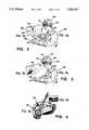
- FIG. 1is a block diagram of the video camera and display system according to the invention.
- FIG. 2illustrates a typical application of a rifle-mounted video camera operating with a free space transmission of video signals to a helmet-mounted video display;
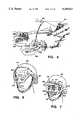
- FIG. 3illustrates an alternative embodiment of the invention in which both the video camera and display are helmet mounted
- FIG. 4illustrates a vehicle guidance system including an outside mounted video camera transmitting a video image to the driver concealed within the vehicle;
- FIG. 5illustrates an application of the invention utilizing an air-to-ground free space transmission of an image, and a ground-to-ground physical transmission medium
- FIG. 6is an isometric view of one embodiment of a helmet-mounted image display system employing holographic display techniques
- FIG. 7is an isometric view of a headgear-mounted image display system employing a beam splitter which can swing out of the user's line of sight;
- FIG. 8illustrates helmet-mounted video display apparatus for allowing split image viewing of the video image as well as the object in the person's line of sight
- FIG. 9illustrates head gear incorporating both a video display and night vision equipment
- FIG. 10is an oblique view of a video display, hingeably mounted to a headgear
- FIG. 11is a side view of the headgear mounted video display of FIG. 10;
- FIG. 12illustrates night vision equipment mounted to a helmet, and coupled by a physical transmission medium to a display
- FIG. 13is a cross-sectional view of an armored military vehicle having omnidirectional image transmitting capabilities within the vehicle;
- FIG. 14depicts in block diagram form the major components of the video display equipment
- FIG. 15illustrates alternative switchable transmission paths between a video camera and a remotely located video display according to the invention
- FIG. 16graphically depicts the atmospheric absorption characteristics with respect to transmission carrier wavelength
- FIG. 17shows a networking scheme used between a single video camera and a plurality of remotely located display units
- FIG. 18shows another networking scheme used in selectively viewing one of a plurality of images generated by plural remotely located video cameras
- FIG. 19illustrates a helmet-mounted switching arrangement for selective presentation of an image from one of the plural cameras shown in FIG. 18;
- FIG. 20illustrates a vehicle guidance system for use in connection with low probability of intercept of nocturnal activities
- FIG. 21illustrates a nonvisible light transmitter for use in conjunction with the system of FIG. 20.
- FIG. 1 of the drawingsThe video system according to the invention is shown generally as reference character 10, and includes an imager shown as a video camera section 12 employed separate and apart from an imager shown as a video display 14.
- a video camera section 12employed separate and apart from an imager shown as a video display 14.
- the object to be viewedis shown as an armored vehicle 16, and the image thereof provided by the video display equipment 14 is shown as reference character 18.
- the video camera 12includes optical imaging system 20 coupled to a video processing sensor system 22 which, in turn, is coupled to a video transmitter system 24.
- a video display unit 26optionally provided integral with the camera is a video display unit 26.
- the optical imaging system 20comprises a lens and filter assembly for providing a clear and accurate image of the vehicle 16 to the processing system 22.
- the optical imaging system 20may be of the conventional type which provides optical correction and adjustment of objects characterized by visible light radiation.
- the system 20may also be of the type which processes an infrared characterizations of the object. A resultant image of the particular type of characterization is coupled to the video processing system 22.
- the optical imaging system 20may also be of the type which is responsive to thermal radiation which is characteristic of the object, or include night vision capabilities.
- the noted types of imaging systemsare readily available, and adaptable to the video camera 12 according to the invention.
- the video processing system 22produces an electrical signal representation of the optical image and couples the electrical signals to the video transmitter 24.
- the electrical video signalis also coupled to the optional video display 26 which is integral to the camera 12.
- the optional video display system 26converts the electrical signals of the object 16 back into an optical characterization thereof so as to be observable by a person.
- the integral video display unit 26a viewer can initially set up the camera 12 and use such display 26 for aligning the camera 12 with respect to a particular scene. This can be done without operating the video transmitter 24, and thus no signal is radiated in the immediate area of the camera 12.
- the video transmitter system 24provides the transmitting equipment to produce a video signal appropriate for transmitting over a desired medium.
- the transmitted signal 27is shown transmitted in a free-space medium. That is, the video signal is transmitted through the atmosphere without a physical or hardware connection between the camera 12 and the remote video display 14.
- the video transmitter system 24can be of the type adapted for modulating the video signal onto an electrical carrier of a desired frequency, or onto a carrier in a frequency band which is in the visible light range, or above such range.
- the video transmitter system 24may be dispensed with entirely, whereupon the electrical video signal is coupled directly to the video display 14 by a coaxial cable, or other suitable conductor.
- the transmission mediummay include a fiber optic bundle. In this event, the video transmitter system 24 would include an electrical to optical converter.
- the remotely located video display 14is provided with a video receiver system 28 for receiving the video signal transmitted by the camera 12.
- the video receiver system 28is coupled to a video monitor system and display 30 which regenerates an optical image of the object 16 from the electrical characterization of such image.
- An optical viewer 32comprises a lens arrangement for providing optical correction, magnification or other adjustment for presentment of the image to the viewer 34.
- the image 18can be observed either from the remotely located display 14 or the optional integral video display 26, if provided.
- FIG. 2there is shown an application of the invention which is envisioned to be advantageous for combat personnel.
- a soldier 36is equipped with a rifle 38 to which a video camera 12 is mounted.
- the video camera 12is fastened to the rear portion of the rifle barrel and above the sight mechanism so as to provide an unobscured aim of the rifle, should the soldier use the weapon in a conventional manner.
- the video camera 12is shown equipped with an infrared or thermal detector, comprising the optical imaging system 20.
- the soldier 36is provided with a helmet 40.
- the video display equipment 14which receives free space video transmissions from the camera 12 to thereby provide the solder 36 with an infrared (IR) generated image without having to continuously look through a rifle-mounted IR equipment.
- the video display 14is shown fastened to the helmet by a strap 42, which strap is fixed to the helmet by rivets (not shown) or other suitable means.
- the video display 14is also depicted receiving free-space transmissions of the camera-generated video image.
- the solder 36is outfitted with a screen 44, goggles or other similar eyewear on which the image of the object can be holographically presented.
- the image 46is shown removed and disposed in a frame 48 in the manner presented by the display 14 to the soldier 36.
- the image 46can also be superimposed on a reticle 50 which provides the soldier 36 information such as range, size, elevation, etc.
- Holographic projection systemsare well-known in the art and are readily adaptable for use in the noted example.
- FIG. 2provides many advantages to the combat solder.
- a gunner in an armored vehicle equipped with the camera 12 and the helmet-mounted display 14 of the inventioncan reload or carry on other operations while watching a target through the head-mounted display.
- the inventionmay significantly reduce the time to thus aim and fire the weapon.
- a foot soldier equipped with a camera-mounted rifle 38 and a helmet-mounted video display 14the soldier can aim the weapon from a full defilade position and shoot from the hip.
- a soldercan also wear a gas mask without impairing or making more difficult the aiming of the weapon 38.
- the head-mounted feature of the video display systemsecures the display, and thus the video image of the object with respect to the observer's eyes.
- FIG. 3illustrates another embodiment of the invention wherein both the video camera 12 and the display 14 are helmet-mounted.
- the video camera 12 shown in FIG. 3is provided with a thermal or infrared detector 52. Again, a video image of the thermal representation of the object is transmitted by free space 54 to the video display 14.
- the video camera 12can be mounted to the helmet 40 by any suitable securing means.
- the image 56 displayed to the soldier 36is shown as a motorized gun emplacement, thereby yielding an indication of the thermal characteristics of the motor and the personnel around the target.
- FIG. 4illustrates an additional application of the invention.
- a video camera 57is mounted exterior to an armored vehicle 58 for providing a view of the terrain in front of the vehicle 58.
- the video image of the objectis again transmitted by free space techniques to a receiver 59.
- the receiver 59may be coupled by a coax or fiber optic line to a video display (not shown) mounted to the helmet of the tank driver.
- the driver(not shown) can then assume other duties within the vehicle without having to constantly look through a periscope, peephole or at a dash-mounted CRT display.
- FIG. 5depicts another application of the invention.
- An aircraft 60can fly into a position of surveillance of a target 61 and relay an image thereof to ground personnel 62. Based upon the image displayed on the helmet apparatus 63 of the ground personnel 62, appropriate gun control parameters can be keyed into a remote fire control unit 64 to aim the vehicle mounted weapon 65 at the target 61.
- the remote control 64is connected to the vehicle-mounted weapon 65 by a secure fiber optic fire control link 66.
- FIGS. 6 and 7illustrate other helmet-mounted video display arrangements where the corresponding parts thereof are identified by the same reference characters as shown in FIGS. 2 and 3.
- the display screen 44is formed integral with the video display 14, and the combination is pivotally mounted to the helmet 40 by a screw 67.
- the display screen 44 and the display unit 14can be rotated upwardly out of the line of sight of the soldier.
- Display screen 44is transparent so the soldier may see through the screen when he is not focussing on images on the screen.
- the display unit 14houses the projection and display optics as well as the video link receiver and power supply.
- a video receiver fish eye objective lens and detector assembly 68receive the free space optical radiation of an image transmitted from a remote location.
- the remote image transmittermay be gun-, vehicle- or aircraft-mounted, or mounted to a tripod.
- FIG. 7illustrates a headgear 69 equipped with the video display 14.
- the headgear 69is mounted to the user's head by a strap 70.
- the helmet 40fits over the headgear strap 70 and provides conventional protection.
- a beamsplitter video screen 71provides the medium upon which the image is protected by the display unit 14.
- the beamsplitter screen 71is hinged 72 so that it can be removed from the soldier's line of sight.
- a focus and lateral adjustment 73provides three axis adjustments to properly focus the projected image in front of the user's eye.
- An off-on switch 74is manually operated to render the electrical circuits of the display unit 14 operational.
- FIGS. 8-11illustrate various other embodiments of the invention secured to the head of a soldier.
- a video receiver 75is mounted to a face frame 76 which is fastened to the person's head by an adjustable headdress strap 77.
- the face frame 76is molded in the general shape of the facial features surrounding a person's eyes and nose.
- a helmet 40may be worn over the display headdress, and thus the cranial protection of the person need not be compromised.
- the helmet 40is secured to the head of a person by a combined chin strap 78 and a depending side strap 79.
- the video receiver 75is secured to the face frame 76 and is thus made integral therewith so that the video receiver 75 ideally follows the motions of the observer's head.
- the video receiver 75is connected by a cable 80 to an electrical or optical antenna for receiving transmissions from a remotely located camera.
- an image viewer or screen 81such as a vacuum fluorescent display, a cathode ray tube, an electroluminescent display, or a liquid crystal display. All such types of displays can be obtained in miniature form suitable for use as described herein.
- One type of miniature display particularly suitable for useis the vacuum fluorescent display described in U.S. Pat. No. 4,081,716, and may be obtainable from ISE Electronic's Corp., ISE, Japan. This display is approximately 7 mm by 10 mm, operates on only 15 volts and thus is ideally suited both as to size and weight for use with the invention.
- the optical viewer 81is optically coupled to the receiver 75 so as to present an image to the person corrected with respect to focus, magnification and other appropriate parameters. As noted in FIG. 8, the optical viewer 81 redirects the image from a horizontally directed image plane to a vertical image plane adjacent one of the observer's eyes.
- a partially reflecting mirror 82is mounted to the optical viewer 81 at an angle of about 45 degrees, and is disposed directly under the exit lens 83 of the optical viewer 81. The redirected image of the object is thus reflected from the mirror 82 and presented for viewing to the observer.
- the reflecting mirror 82is mounted within a frame which is pivotally mounted 84 to the optical display 81. The person can thus swing the reflecting mirror 82 upwardly and out of the line of sight vision of the eye with which it is aligned. Hence, the person can observe the surroundings in the event a video display is not desired.
- a switch 86is mounted to the face frame 76 for providing electrical power control of the video receiver 75.
- the switch 66is wired to the video receiver 75 to provide on-off operation.
- the switch 86is mounted at the foremost part of the face frame 76 so as to be readily accessible for operation by the wearer of the headdress.
- FIG. 9illustrates an adaptation of a video display 88 with night vision equipment 90 to provide the viewer 92 with alternative image characterizations of an object.
- the video display 88 and the night vision equipment 90are disposed in the line of sight division of the respective left and right eye of the observer 92.
- the face frame 94 of this embodimentfits flush against the face of the wearer 92, and includes an outwardly extending shell 96 which houses the video display 88 and night vision equipment 90.
- the video display 88 and night vision equipment 90are secured within the face frame shell 96 and are thereby protected.
- the face frame 94is secured to the head of the wearer 92 by an adjustable strap 98. With this arrangement, the vision equipment 88 and 90 can only be removed by removing the face frame 94 from the head of the wearer 92.
- the night vision equipment 90includes a conventional image intensifier tube 100 which presents an electronic light amplified presentation of the object, with only very small amounts of light illuminating the object.
- starlightis sufficient to illuminate a distant object for easy viewing on the backside of the image intensifier tube 100.
- the video display 88has an inherent narrow field of vision. Thus, objects peripheral to the line of sight vision, as viewed through the video system, are generally not displayed. This creates a disorienting affect when it is necessary for a person to freely move about. The tendency is, for the wearer who depends entirely on the video system, to constantly look from side to side to effectively increase the field of view.
- the wearer 92can look through both the video display 88 and the night vision equipment 90 and gain advantage of both types of optical equipment.
- the night vision equipment 90can be used to view the general environment disposed in front of the person 92, while the video display 88 permits the wearer 92 to then focus on objects which would not otherwise be in the line of sight vision.
- a headgear-mounted video displayis shown in FIG. 10.
- a helmetmay or may not be needed with this alternative.
- the headgear 102provides a headdress to which a flat panel video monitor or display 104 is hingeably mounted.
- a helmet 40is shown worn over the video display headgear 102.
- the headgear 102is shown for mounting the video display 104 adjacent the eyes of a wearer 106.
- the details of the headgear 102are disclosed in more detail in U.S. Pat. No. 4,703,879, and entitled Night Vision Goggle Headgear.
- the video display 104is mounted by a pivotal connection 108 to an overhanging frame structure 110 so that the video display 104 is cantilevered in front of the viewer's eye.
- the frame structure 110is formed integral with a headband 112 of the headgear 102. Straps 114, 116, 118 and 120 secure the headgear 102 to the wearer's head. With this arrangement, a helmet 40 can be easily worn, if desired, over the headgear 102 and thus facilitate full vision capability as well as protection.
- a video display systemis shown in FIG. 12 receiving an image from helmet-mounted night vision equipment 121.
- the night vision equipment 121is fixed to the helmet 40 so that whenever the user turns his head, the corresponding view is displayed by the display unit 14.
- the night vision equipmentprovides an image of the object through a physical conductor 122 to the display unit 14.
- the physical conductor 122may comprise a coaxial cable or fiber optic cable. This embodiment is tailored to the exclusive use of the display in low light conditions. However, the night vision equipment can be replaced with a thermal or infrared sensitive unit.
- FIG. 13is illustrative of yet another application of the invention, wherein an armored vehicle receives video transmissions 123 from a remotely located imager (not shown).
- a receiver unit 124 mounted within the vehicleretransmitts the video image omnidirectionally. In this manner, each person within the vehicle who is equipped with a head mounted display 125 can observe the image. There is a low probability of intercept of the video signals retransmitted within the vehicle due to the enclosed nature thereof.
- FIG. 14illustrates a detailed block diagram of a video display receiver system 126 of the invention.
- an optical to electrical transducer 127receives free space radiation 128 from a video transmitter (not shown) encoded with information relating to the object.
- the radiation 128may be characterized by a wavelength either in the visible light range, or shorter.
- the optical to electrical transducer 127may comprise, for example, a material disposed in the path of the radiation 128 and responsive to the particular wavelength of the radiation 128. The material thus produces an electrical output representative of the modulated free space video signal.
- a video demodulator 129is coupled to the transducer 127 for demodulating a video signal into constituent electrical components suitable for driving a video display.
- a video display driver 130receives the coded signal from the video demodulator 129 and drives a display 132 so that an image of the object is displayed thereon.
- the video display driver 130is of conventional design and adapted to drive a raster/scan type of display, if such type of display is employed. If a matrix type of display is used, the driver 130 would be adapted for individually addressing each element of the matrix with a signal having characteristics of the brightness with which that element should be illuminated.
- the display 132is of the miniature, lightweight, low power type suitable for mounting to the helmet or headgear of a wearer.
- a vacuum fluorescent display of the type disclosed in the noted patenthas these qualities.
- An eyepiece assembly 134is disposed in the output optical path of the display 132 and comprises plural lenses, such as 136, for interfacing the image on the display 132 to the human eye 138.
- the eyepiece assembly 134may include the various combinations of lens types to suit individual needs.
- the eyepiece assembly 134may be used in conjunction with the partial reflecting mirror 82 of FIG. 8.
- FIG. 15there are shown the details of an arrangement for coupling a video camera transmitter 140 to the video display receiver 126.
- the imager or camera 140is shown mounted on a tripod 141.
- the video camera transmitter 140can be located remotely from the head-mounted video display receiver 126, such as on a weapon, a vehicle or also on a tripod.
- These suggested mounting locationsare only exemplary, and are not to be interpreted as limiting the applicability of the invention to particular situations.
- the arrangement of FIG. 15provides dual modes of video transmission between the video camera transmitter 140 and the video display receiver 126. In one mode of operation, the video information is transmitted in a free space medium 128 from the transmitter 140 to the receiver 126.
- the modulated video signalis transmitted from the transmitter 140 to the receiver 126 by a physical medium, such as a fiber optic or a coaxial cable 144.
- the physical medium 144can be advantageously used in those situations where the utmost security of the video signal is desired, or where the atmospheric conditions do not permit an acceptable medium for a free space transmission.
- the video camera transmitter 140includes a video transmitter 146 for transmitting a modulated video signal of the image on a pair of output conductors 148 and 150.
- Transmitter line 148drives an electrical to free space transducer 152 for transmitting the free space video signal 128.
- Transmitter conductor 150drives the physical conductor 144 with appropriate video signals.
- Physical conductor 144can be of the coaxial type, in which event the signals on video transmission line 150 are electrical in nature. However, the physical conductor 144 can also be a fiber optic bundle, wherein the signals in transmission line 150 would be converted to modulated light signals.
- the electrical to light transducer 152 of the video camera transmitter 140includes a reflector 154 for providing a desired directional radiation characteristic.
- the reflector 154can be shaped in a parabolic form to focus the transmitted video signal in a beam collimated in a desired direction.
- the video signalmay be transmitted omnidirectionally, wherein any video display receiver in the area would be capable of receiving the video signal.
- the electrical transducer 152further includes a light transmitting element 156 which converts the video signal on transmission conductor 148 into modulated light signals.
- the nature of the materials comprising the element 156determines primarily the wavelength of the transmitted energy in free space 128. Materials are presently available to provide free space transmissions from the short ultraviolet spectrum to the far infrared spectrum.
- the video display receiver 126is provided with an optical to electrical transducer 159 for converting the free space 128 transmission of the video signal into corresponding electrical representations. Further details of the transmitter transducer 156 and the receiver transducer 159 will be disclosed below.
- a focusing lens 160is disposed in the path of the free space video signal 128 for focusing the light radiation on the electrical transducer 159.
- the lens 160is preferably constructed of a material which has a low degree of attenuation to the particular wavelength of the free space transmission.
- the material with which the optical to electrical transducer 159 is constructedis also highly responsive to the particular frequency or wavelength of the free space radiation.
- the video display receiver 126is provided with a feature in which the image chosen to be displayed on the video display 132 is automatically switchable from the free space transmission medium 128 to the physical medium 144.
- An automatic selection means 160is provided for automatically selecting the physical medium 144 when the cable is connected to the video display receiver 126, and for selecting the free space transmission 128 when the physical medium 144 is disconnected.
- the video display receiver 126includes a switch 162 switchable between a first position 164 and a second position 166 in response to the electrical energization of an associated relay coil 168. When the switch 162 is in the first position 164, the video signal transmitted on the physical medium 144 is coupled to the video demodulator 129. On the other hand, when the switch 162 is switched to the second position 166, the free space transmission 128 of the video signal is coupled to the video demodulator 129.
- the automatic switching mechanism 160further includes a physical medium connection arrangement 170 for ohmically connecting the physical medium 144 to the video display receiver 126. Also included is a ground detector 172 coupled between the ohmic connection arrangement 170 and the switching relay 168.
- a physical medium connection arrangement 170for ohmically connecting the physical medium 144 to the video display receiver 126.
- a ground detector 172coupled between the ohmic connection arrangement 170 and the switching relay 168.
- the physical medium 144is a coaxial cable carrying electrical video signals, such cable is commonly terminated with a BNC type metallic connector 174.
- the BNC connection 174is attachable to a corresponding coaxial cable 176 fastened to a frame part 178 of the video display receiver 126.
- a spring-loaded probe assembly 180insulated from the frame 178.
- the spring-loaded end 182Disposed on the other side of the frame 178 is the spring-loaded end 182 which is conductive and engagable with the metallic connector 174.
- the metallic connector 174makes electrical contact with the spring-loaded end 182.
- the metallic connector 174is connected internally to a shield or ground conductor of the cables 144 and 176.
- the coaxial cable 176includes a signal conductor 184 for carrying the video signals, and a shield conductor 186 for providing electromagnetic shielding to the signal conductor 184.
- the ground detector 172detects this as a connection of the physical medium 144 to the video receiver 126, whereupon relay 168 is operated.
- the ground detector 172can be, for example a logic NOR gate for providing a logic output high in response to input logic low levels representative of the ground potential on the shield conductor 186 and the conductor 184.
- the relay contacts 162are shown in FIG. 15 in the operated position, illustrating that when the physical medium 144 is connected to the video display receiver 126, the signal carried on conductor 184 is coupled to the video demodulator 129.
- the connector 174 of the physical medium 144is disconnected from the video display receiver 126, the ground potential will be removed from conductor 180, whereupon the output 188 of the ground detector 172 will be driven to a logic low, thereby releasing relay 168.
- the switch 162will then make contact with the second contact 166 and thereby automatically couple the free space transmission 128 of the video signal to the video demodulator 129.
- Those skilled in the artmay devise other physical conductor switching arrangements 170 or detectors 160 which will operate with equal effectiveness.
- the wavelength for transmitting the video signalis selected so as to provide transmissions having a low probability of intercept, thereby preventing the reception of the signals by the enemy or other unauthorized persons.
- One technique for accomplishing the transmission having a low probability of interceptis to assure that the transmission of the video signal is restricted to a narrowly defined area.
- the transmission medium for the video signalis a physical conductor
- the reception of the signalis limited only to the receiver connected therewith. The secrecy problem is exacerbated when it is desired to transmit the video information through the atmosphere.
- the area of receptionis less defined, and is determined by many atmospheric conditions which are susceptible to change at unpredictable times.
- one wavelength selected for transmitting the video signal in free spaceis chosen such that a predictable signal absorption occurs, notwithstanding day, night or weather conditions. This assures that the video signal will not be received beyond a maximum peripheral area surrounding the transmitter. While many parameters of the atmosphere exist which affect the absorption of a radiated wave, the water vapor content of the atmosphere has been chosen as the parameter to which absorption of a particular transmission wavelength is correlated. Reference is made to FIG. 16 where there is graphically depicted the transmittance of a radiated wave as a function of water vapor normally occurring in the atmosphere. The transmittance is represented by the vertical axis of the graph, while the wavelength of the radiated signal is shown on the horizontal axis.
- the atmospheric transmission of a signal transmitted at a wavelength of 1.39 umis about 0.001 percent. It can be seen that by selecting a wavelength in this range, the atmospheric absorption thereof does not permit the signal to reach distant areas. As a result, it is assured that the video signal modulated on such a wavelength will not extend beyond the area of its intended reception.
- the transmission of the video signal at a wavelength of about 1.39 umprovides certain advantages over the other frequencies associated with the other maximum absorption peaks. Transmitters and receivers operating in this wavelength range are not unduly complicated and do not require the attention to additional considerations, as does the transmission or reception at the other noted wavelengths.
- the atmospheric attenuationis somewhat less than at 1.39 um.
- the absorption of the signal at a wavelength of 1.9 umis substantially identical to that associated with the 1.39 um wavelength, but additional cooling may be required for the transmitter and receiver.
- the foregoing analysiscan also be made to select a transmitting wavelength having desired absorbtion characteristics based on other atmospheric elements. For instance, particular wavelengths can be selected to achieve desired absorbtion characteristics in carbon dioxide or ozone.
- a transmitting element 156such as shown in FIG. 15, fabricated of either a gallium indium arsenide (GaIAs) material or a gallium arsenide antimonide material emits frequencies in the 1.39 um range when driven or excited by an electrical signal When so driven, the transmitting element 156 will radiate a carrier frequency in the 1.39 um range and communicate the video information modulated thereon.
- the lens 160 in the video display receiver 126can be constructed of glass, arsenic trisulphide sapphire, cadmium sulphide or magnesium oxide.
- the optical to electrical transducer 159may be constructed of a material similar to that of the transmitting element 156 and thereby convert the free space radiated video signal into a corresponding electrical signal.
- the optical to electrical transducer 159is perferably constructed of the same material as the transmitting element 156.
- FIGS. 17 and 18Shown in FIGS. 17 and 18 are additional features of the invention.
- the utility of the inventionis enhanced when using plural remote video display receivers, even though only a single video camera is operational, or is available.
- FIG. 17illustrates a single rifle-mounted video camera transmitter 196 and a plurality of helmet-mounted video display receivers 198-204.
- the video transmitter 196is provided with a transmitter element (not shown) fabricated of a material which transmits the video image in free space at a desired wavelength.
- the video display receivers 198-204are each provided with a material which is responsive to the same wavelength radiation to thereby receive and decode the video signal as modulated by the transmitter 196.
- each video display receiver 198-204is contructed to allow each of the corresponding persons wearing the helmet-mounted device to view the same object toward which the rifle 206 is aimed. This is especially advantageous in training maneuvers where plural soldiers can view a target sighted from a single weapon. Indeed, with the arrangement set forth above, military trainees need not even be disturbed from classroom instructions on weapons targeting in order to witness the actual sighting and targeting of the remotely located weapon and target.
- FIG. 18The details of another networking technique according to the invention are shown in FIG. 18.
- a single video display receiver 208is helmet-mounted to a soldier 210 who can selectively receive free space transmissions of different video signals from rifle-mounted cameras 212, 214 and 216.
- Each soldier 218-222 carrying a respective rifle 224-228is equipped with a helmet-mounted video display receiver 230-234 so that the particular objects captured by the respective video cameras 212-216 can be seen by the respective soldiers 218-222.
- the transmitting wavelength of the video equipment provided the soldier 218will preferably be different from the wavelength used by the equipment of soldiers 220 and 222. The latter two soldiers 220 and 222 may also be using different wavelength equipment.
- the transmitting and receiving elements with which each soldier 218-222 is equippedwill be constructed of different materials, and thus will be nonresponsive to the transmission or reception of the other soldiers' equipment.
- the modulation frequencies of the various transmittersmay be different, and the soldier can select which scene he will view by tuning a filter in his receiver.
- the video display receiver 208is selectively responsive to the transmission of each of the video camera transmitters 212-216.
- a switch 236which allows the helmet wearer 210 to selectively receive the video signal of one of ten transmitters 212-216.
- Conventional switchesare available for switching or controlling different video channels.
- FIG. 19an exemplary switching arrangement 236 is shown, adaptable for use in the example of FIG. 18.
- Micrometer wavelength radiationdenoted again by reference character 128, emitted from any of the video camera transmitters 212-216 is focused by an object lens 158 onto a plurality of micrometer wavelength sensitive elements 238, 240 and 242.
- Each element 238-242is responsive to a different narrow band of wavelengths which correspond to the different wavelengths transmitted by the respective video camera transmitters 212-216.
- element 238is responsive to a free space wavelength transmitted only by video camera transmitter 212.
- Elements 240 and 242receive only transmissions from respective camera transmitters 214 and 216.
- the manually operated switch 236is switchable by the soldier 210 to position 244, 246 and 248 corresponding to the free space video camera transmitters 212-216.
- the single video signal selected by the soldier 210is then switched through the manually operated switch 236 to the video demodulator 129 of FIG. 14.
- the switch 236may also be ganged to a similar switch in the demodulator 129 to change an oscillator frequency such that one given video, IF (intermediate frequency) frequency is produced, notwithstanding which video transmission frequency or wavelength is selected. It is of course possible to switch or multiplex more than the number of free space transmissions shown in FIG. 18, as well as make the switchable connection within the video display receiver at points other than in the video demodulator 12.
- FIG. 20is illustrative of a vehicle 250 equipped with apparatus incorporating the principles and concepts of the invention.
- a driver 252 of the vehicle 250is provided with a video display receiver 254 which can receive micrometer wavelength video transmissions either through free space, or through a physical medium as described above.
- the vehicle 250is equipped with standard incandescent lamps 256 and 258, as well as a pair of transmitters 260 and 262 for transmitting radiation in the nonvisible light spectrum.
- the nonvisible light spectrumcan comprise radiation wavelengths between short ultraviolet and far infrared. In this application, it is desirable to select a wavelength which is highly susceptible to atmospheric absorption. In this manner, the lamps 256 and 258 may be turned off and transmitters 260 and 262 turned on.
- the driver 252can detect the light from lamps 256 and 258 with his receiver 54 while a remote observer is not able to detect the light.
- a receiver/transmitter unit 264which has a receiver input 266 responsive to the nonvisible light reflected from objects in the path of the vehicle 250.
- the unit 264further includes a transmitter 268 for transmitting free space radiation to a video display receiver 254. Characterizations of the terrain or objects in the path of the vehicle 250 are thus transmitted by transmitter 268.
- the wavelength of radiation transmitted by transmitters 260 and 262need not be the same as that transmitted by the transmitter 268.
- the receiver element (not shown) in the input 266 of the unit 264must be responsive to radiation wavelengths in the range emitted by transmitters 260 and 262.
- an appropriately equipped soldier 252, or other similarly equipped foot soldiercan look straight into the main transmitters 260 and 262 without saturating or otherwise affecting the quality of the image displayed on the helmet-mounted display 254.
- each transmitter unit 260 and 262A vehicular micrometer wavelength transmitter is shown in exemplary form in FIG. 21.
- Each element (which may for example be an LED) of an array of transmitting elements 272is mounted in a small parabolic reflector 270 (see exploded view in FIG. 21).
- An electrical cable 274provides the driving energy for exciting the elements 272 so that radiation of the desired wavelength can be emitted.
- the reflectors 270have reflective interior surfaces 276 so that a majority of the energy radiated from each of the elements 272 is directed in a forwardly direction in the path of the vehicle 250.
- Each radiating element 272need not be driven by a separate signal, but rather all radiating elements may be driven together by a common driving electrical signal on cable 274.
- a video transmitter and display receiver arrangementwhich provides a significant advantages when used either in military or civilian applications.
- the inventionmay find a variety of applications in the civilian environment, such as in news reporting, fire fighting or law enforcement.
- the inventionprovides additional measures of security in that the reception of the video signal is limited to a relatively predefined area.
Landscapes
- Physics & Mathematics (AREA)
- Engineering & Computer Science (AREA)
- General Physics & Mathematics (AREA)
- Optics & Photonics (AREA)
- General Engineering & Computer Science (AREA)
- Theoretical Computer Science (AREA)
- Signal Processing (AREA)
- Multimedia (AREA)
- Radar, Positioning & Navigation (AREA)
- Business, Economics & Management (AREA)
- Educational Administration (AREA)
- Educational Technology (AREA)
- Closed-Circuit Television Systems (AREA)
Abstract
Description
Claims (6)
Priority Applications (1)
| Application Number | Priority Date | Filing Date | Title |
|---|---|---|---|
| US07/630,367US5200827A (en) | 1986-07-10 | 1990-12-18 | Head mounted video display and remote camera system |
Applications Claiming Priority (2)
| Application Number | Priority Date | Filing Date | Title |
|---|---|---|---|
| US06/883,994US4786966A (en) | 1986-07-10 | 1986-07-10 | Head mounted video display and remote camera system |
| US07/630,367US5200827A (en) | 1986-07-10 | 1990-12-18 | Head mounted video display and remote camera system |
Related Parent Applications (1)
| Application Number | Title | Priority Date | Filing Date |
|---|---|---|---|
| US07/507,978ContinuationUS5005213A (en) | 1986-07-10 | 1990-04-11 | Head mounted video display and remote camera system |
Publications (1)
| Publication Number | Publication Date |
|---|---|
| US5200827Atrue US5200827A (en) | 1993-04-06 |
Family
ID=27091134
Family Applications (1)
| Application Number | Title | Priority Date | Filing Date |
|---|---|---|---|
| US07/630,367Expired - LifetimeUS5200827A (en) | 1986-07-10 | 1990-12-18 | Head mounted video display and remote camera system |
Country Status (1)
| Country | Link |
|---|---|
| US (1) | US5200827A (en) |
Cited By (107)
| Publication number | Priority date | Publication date | Assignee | Title |
|---|---|---|---|---|
| US5365057A (en)* | 1993-07-02 | 1994-11-15 | Litton Systems, Inc. | Light-weight night vision device |
| WO1996009614A1 (en)* | 1994-09-12 | 1996-03-28 | Ziegra Richard C | Video audio data remote system |
| WO1996036898A3 (en)* | 1995-05-15 | 1997-02-06 | Hughes Aircraft Co | Low-cost light-weight head-mounted virtual-image projection display with low moments of inertia and low center of gravity |
| US5677795A (en)* | 1995-01-10 | 1997-10-14 | Hughes Aircraft Company | Modular helmet-mounted display |
| US5711104A (en)* | 1996-12-19 | 1998-01-27 | Schmitz; Geoffrey W. | Small arms visual aiming system, a method for aiming a firearm, and headgear for use therewith |
| US5748264A (en)* | 1995-01-10 | 1998-05-05 | Hughes Electronics | Distortion Corrected display |
| FR2756939A1 (en)* | 1996-12-05 | 1998-06-12 | Deroudille Gilles | Head mounted camcorder viewing system |
| US5801866A (en)* | 1992-08-27 | 1998-09-01 | Trex Communications Corporation | Laser communication device |
| US5834676A (en)* | 1996-08-12 | 1998-11-10 | Sight Unseen | Weapon-mounted location-monitoring apparatus |
| US5914661A (en)* | 1996-01-22 | 1999-06-22 | Raytheon Company | Helmet mounted, laser detection system |
| US5926318A (en)* | 1998-04-06 | 1999-07-20 | Optimize Incorporated | Biocular viewing system with intermediate image planes for an electronic display device |
| US6028627A (en)* | 1997-06-04 | 2000-02-22 | Helmsderfer; John A. | Camera system for capturing a sporting activity from the perspective of the participant |
| WO2000003192A3 (en)* | 1998-07-13 | 2000-03-30 | Recon Optical Inc | Vision module for weapon system optical sight |
| EP0983477A4 (en)* | 1997-05-16 | 2000-07-12 | Yair David | Aiming apparatus |
| WO2001001706A1 (en)* | 1999-06-30 | 2001-01-04 | Phatrat Technology, Inc. | Event and sport performance methods and systems |
| US6215461B1 (en)* | 1996-08-30 | 2001-04-10 | Minolta Co., Ltd. | Image viewing system and image display device |
| US6219186B1 (en) | 1998-04-06 | 2001-04-17 | Optimize Incorporated | Compact biocular viewing system for an electronic display |
| WO2001033283A1 (en)* | 1999-10-29 | 2001-05-10 | Microvision, Inc. | Linked scanner imaging system and method |
| US6230327B1 (en)* | 1998-03-12 | 2001-05-15 | La Soudure Autogene Francaise | Protective mask for welding with viewing in the infrared and use of such a mask |
| US6237462B1 (en)* | 1998-05-21 | 2001-05-29 | Tactical Telepresent Technolgies, Inc. | Portable telepresent aiming system |
| US6255650B1 (en) | 1998-12-11 | 2001-07-03 | Flir Systems, Inc. | Extreme temperature radiometry and imaging apparatus |
| US20020071050A1 (en)* | 1999-03-08 | 2002-06-13 | Larry Holmberg | Game hunting video camera |
| US20020088925A1 (en)* | 1998-08-05 | 2002-07-11 | Microvision, Inc. | Low light viewer with image simulation |
| US6449419B1 (en) | 2000-09-05 | 2002-09-10 | Richard Brough | Optical viewing system and clamping device therefor |
| WO2003007612A1 (en)* | 2001-07-11 | 2003-01-23 | Cch Sa | Observation device |
| US6560029B1 (en)* | 2001-12-21 | 2003-05-06 | Itt Manufacturing Enterprises, Inc. | Video enhanced night vision goggle |
| US6583772B1 (en) | 1998-08-05 | 2003-06-24 | Microvision, Inc. | Linked scanner imaging system and method |
| US20030115661A1 (en)* | 2001-12-21 | 2003-06-26 | Dobbie Blair R. | Headmount apparatus for attaching and supporting devices |
| US20030122958A1 (en)* | 2001-12-27 | 2003-07-03 | Jules Olita | Helmet-mounted thermal imaging system |
| US20030153506A1 (en)* | 2000-06-10 | 2003-08-14 | Ruth Bylund | Combination product comprising melagatran and factor VIIa inhibitor |
| WO2003074982A1 (en)* | 2002-03-01 | 2003-09-12 | Flir Systems Ab | Infrared camera with slave monitor |
| US20040125047A1 (en)* | 2002-08-23 | 2004-07-01 | Kopin Corporation | Headgear system with display |
| US6899539B1 (en) | 2000-02-17 | 2005-05-31 | Exponent, Inc. | Infantry wearable information and weapon system |
| US20050179799A1 (en)* | 2004-02-14 | 2005-08-18 | Umanskiy Yuriy K. | Firearm mounted video camera |
| US20050190550A1 (en)* | 1999-11-15 | 2005-09-01 | Kennedy Jeffrey P. | Portable long range searchlight with telescopic viewing and imaging systems |
| AU2002359759B2 (en)* | 2001-12-21 | 2006-03-02 | Exelis Inc. | Video enhanced night vision goggle |
| US20060055786A1 (en)* | 2004-03-09 | 2006-03-16 | Viosport | Portable camera and wiring harness |
| EP1691163A1 (en)* | 2005-02-11 | 2006-08-16 | Saab Ab | Arrangement for management of a soldier in networkbased warfare |
| WO2006113369A1 (en)* | 2005-04-13 | 2006-10-26 | Kopin Corporation | Auxiliary targeting viewer |
| US20070067894A1 (en)* | 2005-03-30 | 2007-03-29 | Litton Systems, Inc. | Mount for digitally enhanced night vision device |
| US20070069977A1 (en)* | 2005-09-26 | 2007-03-29 | Adderton Dennis M | Video training system |
| US20070090277A1 (en)* | 2004-10-22 | 2007-04-26 | Gary Palmer | Ruggedized digital low-light viewing device |
| US20070111753A1 (en)* | 2000-12-15 | 2007-05-17 | Vock Curtis A | Personal items network, and associated methods |
| WO2006128648A3 (en)* | 2005-05-30 | 2007-06-14 | Andreas Durner | Electronic day and night vision spectacles |
| US20070165016A1 (en)* | 2003-06-20 | 2007-07-19 | Microvision, Inc. | Apparatus, system, and method for capturing an image with a scanned beam of light |
| USD547346S1 (en) | 2004-03-09 | 2007-07-24 | V.I.O., Inc. | Camera |
| US20070208530A1 (en)* | 1994-11-21 | 2007-09-06 | Vock Curtis A | Activity monitoring systems & methods |
| US20070236384A1 (en)* | 2006-02-12 | 2007-10-11 | Gennadii Ivtsenkov | Cost-effective friend-or-foe (IFF) combat infrared alert and identification system (CID) |
| US20070246641A1 (en)* | 2004-02-27 | 2007-10-25 | Baun Kenneth W | Night vision system with video screen |
| US20070270721A1 (en)* | 2006-05-22 | 2007-11-22 | Apple Computer, Inc. | Calibration techniques for activity sensing devices |
| US20070270663A1 (en)* | 2006-05-22 | 2007-11-22 | Apple Computer, Inc. | System including portable media player and physiologic data gathering device |
| US20080000463A1 (en)* | 2006-06-30 | 2008-01-03 | Larry Holmberg | Crossbow device mount |
| US20080087784A1 (en)* | 2006-10-17 | 2008-04-17 | Larry Holmberg | Device mount with stabilizing function |
| US20080164392A1 (en)* | 2007-01-05 | 2008-07-10 | Larry Holmberg | Device mount system for a weapon |
| US20080306707A1 (en)* | 1994-11-21 | 2008-12-11 | Vock Curtis A | Impact Reporting Head Gear System And Method |
| US20090019176A1 (en)* | 2007-07-13 | 2009-01-15 | Jeff Debrosse | Live Video Collection And Distribution System and Method |
| US20090033736A1 (en)* | 2007-08-01 | 2009-02-05 | John Thomason | Wireless Video Audio Data Remote System |
| US20090045996A1 (en)* | 2007-03-13 | 2009-02-19 | Gennadii Ivtsenkov | Combined IR-RF combat identification friend-or-foe (IFF) system for the dismounted soldier |
| US20090086015A1 (en)* | 2007-07-31 | 2009-04-02 | Kongsberg Defence & Aerospace As | Situational awareness observation apparatus |
| US20090091634A1 (en)* | 2004-02-23 | 2009-04-09 | Xenonics Holdings, Inc. | Digital low-light viewing device |
| US20090255163A1 (en)* | 2002-03-04 | 2009-10-15 | Larry Holmberg | Device mounting system for a weapon |
| US20090267783A1 (en)* | 2005-10-18 | 2009-10-29 | Apple Inc. | Shoe Wear-Out Sensor, Body-Bar Sensing System, Unitless Activity Assessment and Associated Methods |
| US20090322654A1 (en)* | 2003-12-03 | 2009-12-31 | Nikon Corporation | Information display device and wireless remote controller |
| US7643895B2 (en) | 2006-05-22 | 2010-01-05 | Apple Inc. | Portable media device with workout support |
| US7643132B2 (en) | 2002-03-04 | 2010-01-05 | Larry Holmberg | Range finder |
| US7698101B2 (en) | 2007-03-07 | 2010-04-13 | Apple Inc. | Smart garment |
| US7739822B1 (en) | 2007-01-09 | 2010-06-22 | Larry Holmberg | Method and device for mounting an accessory to a firearm |
| US7780363B1 (en) | 2008-01-17 | 2010-08-24 | Larry Holmberg | Device for mounting imaging equipment to a bow and method of recording a hunt |
| US7813715B2 (en) | 2006-08-30 | 2010-10-12 | Apple Inc. | Automated pairing of wireless accessories with host devices |
| US20100258000A1 (en)* | 2005-05-05 | 2010-10-14 | Matthew Charles Hagerty | Wireless, waterproof remote video weapon mounted sighting system, SmartSight |
| DE10048563B4 (en)* | 2000-09-30 | 2010-11-25 | Meissner, Werner | Device for the remote maintenance of technical equipment |
| US20100313461A1 (en)* | 2009-06-16 | 2010-12-16 | Larry Holmberg | Electronic device mount system with strap |
| US7913297B2 (en) | 2006-08-30 | 2011-03-22 | Apple Inc. | Pairing of wireless devices using a wired medium |
| US20110113672A1 (en)* | 2009-11-19 | 2011-05-19 | Larry Holmberg | Remote controlled decoy |
| US20110185479A1 (en)* | 2008-10-29 | 2011-08-04 | Eutemio Rayel Ohno | Preamble |
| US8024884B2 (en) | 2009-06-16 | 2011-09-27 | Larry Holmberg | Electronic device mount system for weapons |
| WO2011129740A1 (en) | 2010-04-16 | 2011-10-20 | Bae Systems Bofors Ab | Method and device for target designation |
| US8046950B2 (en) | 2006-01-06 | 2011-11-01 | Larry Holmberg | Method of attaching device to weapon |
| US8073984B2 (en) | 2006-05-22 | 2011-12-06 | Apple Inc. | Communication protocol for use with portable electronic devices |
| US8240077B2 (en) | 2002-03-04 | 2012-08-14 | Larry Holmberg | Range finder for weapons |
| US8656624B2 (en) | 2010-12-29 | 2014-02-25 | Larry Holmberg | Universal device mount |
| US8656625B2 (en) | 2010-12-29 | 2014-02-25 | Larry Holmberg | Accessory mount |
| USD700962S1 (en) | 2013-03-15 | 2014-03-11 | Bae Systems Information And Electronic Systems Integration Inc. | Gas mask with thermal sensor |
| USD700928S1 (en)* | 2013-03-15 | 2014-03-11 | Bae Systems Information And Electronic Systems Integration Inc. | Goggles and thermal sensor |
| USD702831S1 (en) | 2013-03-15 | 2014-04-15 | Bae Systems Information And Electronic Systems Integration Inc. | Gas mask with thermal sensor |
| USD704328S1 (en) | 2013-03-15 | 2014-05-06 | Bae Systems Information And Electronic Systems Integration Inc. | Gas mask with thermal sensor |
| USD704327S1 (en) | 2013-03-15 | 2014-05-06 | Bae Systems Information And Electronic Systems Integration Inc. | Gas mask with thermal sensor |
| US20140145079A1 (en)* | 2011-07-11 | 2014-05-29 | Nec Corporation | Work assistance system, terminal, method and program |
| USD706414S1 (en) | 2013-03-15 | 2014-06-03 | Bae Systems Information And Electronic Systems Integration Inc. | Gas mask with thermal sensor |
| USD720632S1 (en) | 2013-03-15 | 2015-01-06 | Bae Systems Information And Electronic Systems Integration Inc. | Thermal sensor |
| US9038870B2 (en) | 2012-05-15 | 2015-05-26 | August A. JOHNSON | Head mount apparatus for hands-free video recording with an electronic device |
| US9113061B1 (en) | 2009-08-21 | 2015-08-18 | Nivisys, Llc | System and method for zoom alignment of clip-on digital electro-optic sight |
| USD737955S1 (en) | 2013-03-15 | 2015-09-01 | Bae Systems Information And Electronic Systems Integration Inc. | Gas mask with thermal sensor |
| US9288468B2 (en) | 2011-06-29 | 2016-03-15 | Microsoft Technology Licensing, Llc | Viewing windows for video streams |
| TWI564537B (en)* | 2013-12-02 | 2017-01-01 | 南臺科技大學 | Method and device for enemy gunfire alert |
| US9674409B2 (en) | 2012-09-19 | 2017-06-06 | Michael J. Jones | Image capturing system and method of use |
| US9868041B2 (en) | 2006-05-22 | 2018-01-16 | Apple, Inc. | Integrated media jukebox and physiologic data handling application |
| US9998687B2 (en) | 2012-09-12 | 2018-06-12 | Bae Systems Information And Electronic Systems Integration Inc. | Face mounted extreme environment thermal sensor system |
| EP3376152A1 (en)* | 2017-03-13 | 2018-09-19 | MBDA Deutschland GmbH | Information processing system and information processing method |
| US10182606B2 (en) | 2015-02-05 | 2019-01-22 | Amit TAL | Helmut with monocular optical display |
| CN109922282A (en)* | 2017-12-13 | 2019-06-21 | 德尔格安全股份两合公司 | Thermal imaging camera and thermal imaging camera system |
| US10359256B2 (en) | 2017-01-31 | 2019-07-23 | Hookshottactical, Llc | Camara sight with smart phone mount |
| US10591249B2 (en) | 2015-11-16 | 2020-03-17 | Hookshottactical, Llc | Camera sight device for a weapon |
| US10876816B2 (en) | 2015-11-16 | 2020-12-29 | Hookshottactical, Llc | Camera sight devices and rear viewing camera smart phone mount for a firearm |
| WO2021133317A1 (en)* | 2019-12-23 | 2021-07-01 | Yonar Taner | Camera aided and monitor controlled sight system allowing simultaneous use of two weapons for portable firearms |
| US20230049417A1 (en)* | 2021-08-15 | 2023-02-16 | Colin Richard Buckingham | Portable Optic Stabilizing Carry Device |
| US11965714B2 (en) | 2007-02-28 | 2024-04-23 | Science Applications International Corporation | System and method for video image registration and/or providing supplemental data in a heads up display |
Citations (13)
| Publication number | Priority date | Publication date | Assignee | Title |
|---|---|---|---|---|
| US3674925A (en)* | 1970-12-03 | 1972-07-04 | Us Navy | Cable-less television system |
| US3798796A (en)* | 1972-06-28 | 1974-03-26 | Aerospatiale | Method and equipment for training personnel in the optical tracking of a moving target |
| US4028725A (en)* | 1976-04-21 | 1977-06-07 | Grumman Aerospace Corporation | High-resolution vision system |
| US4081716A (en)* | 1976-03-01 | 1978-03-28 | Ise Electronics Corporation | Fluorescent display elements |
| US4091412A (en)* | 1967-12-01 | 1978-05-23 | The United States Of America As Represented By The Secretary Of The Army | Target designation system |
| US4222880A (en)* | 1977-09-23 | 1980-09-16 | Siemens Aktiengesellschaft | Arrangement for optical transmission of communications |
| US4280125A (en)* | 1979-07-27 | 1981-07-21 | Xerox Corporation | Thin vacuum panel display device |
| US4516157A (en)* | 1982-11-23 | 1985-05-07 | Campbell Malcolm G | Portable electronic camera |
| US4605959A (en)* | 1984-08-23 | 1986-08-12 | Westinghouse Electric Corp. | Portable communications terminal |
| US4703879A (en)* | 1985-12-12 | 1987-11-03 | Varo, Inc. | Night vision goggle headgear |
| US4786966A (en)* | 1986-07-10 | 1988-11-22 | Varo, Inc. | Head mounted video display and remote camera system |
| US4884137A (en)* | 1986-07-10 | 1989-11-28 | Varo, Inc. | Head mounted video display and remote camera system |
| US5005213A (en)* | 1986-07-10 | 1991-04-02 | Varo, Inc. | Head mounted video display and remote camera system |
- 1990
- 1990-12-18USUS07/630,367patent/US5200827A/ennot_activeExpired - Lifetime
Patent Citations (13)
| Publication number | Priority date | Publication date | Assignee | Title |
|---|---|---|---|---|
| US4091412A (en)* | 1967-12-01 | 1978-05-23 | The United States Of America As Represented By The Secretary Of The Army | Target designation system |
| US3674925A (en)* | 1970-12-03 | 1972-07-04 | Us Navy | Cable-less television system |
| US3798796A (en)* | 1972-06-28 | 1974-03-26 | Aerospatiale | Method and equipment for training personnel in the optical tracking of a moving target |
| US4081716A (en)* | 1976-03-01 | 1978-03-28 | Ise Electronics Corporation | Fluorescent display elements |
| US4028725A (en)* | 1976-04-21 | 1977-06-07 | Grumman Aerospace Corporation | High-resolution vision system |
| US4222880A (en)* | 1977-09-23 | 1980-09-16 | Siemens Aktiengesellschaft | Arrangement for optical transmission of communications |
| US4280125A (en)* | 1979-07-27 | 1981-07-21 | Xerox Corporation | Thin vacuum panel display device |
| US4516157A (en)* | 1982-11-23 | 1985-05-07 | Campbell Malcolm G | Portable electronic camera |
| US4605959A (en)* | 1984-08-23 | 1986-08-12 | Westinghouse Electric Corp. | Portable communications terminal |
| US4703879A (en)* | 1985-12-12 | 1987-11-03 | Varo, Inc. | Night vision goggle headgear |
| US4786966A (en)* | 1986-07-10 | 1988-11-22 | Varo, Inc. | Head mounted video display and remote camera system |
| US4884137A (en)* | 1986-07-10 | 1989-11-28 | Varo, Inc. | Head mounted video display and remote camera system |
| US5005213A (en)* | 1986-07-10 | 1991-04-02 | Varo, Inc. | Head mounted video display and remote camera system |
Cited By (213)
| Publication number | Priority date | Publication date | Assignee | Title |
|---|---|---|---|---|
| US5801866A (en)* | 1992-08-27 | 1998-09-01 | Trex Communications Corporation | Laser communication device |
| US5999299A (en)* | 1992-08-27 | 1999-12-07 | Thermotrex Corporation | Laser communication device |
| US5365057A (en)* | 1993-07-02 | 1994-11-15 | Litton Systems, Inc. | Light-weight night vision device |
| WO1996009614A1 (en)* | 1994-09-12 | 1996-03-28 | Ziegra Richard C | Video audio data remote system |
| US5619183A (en)* | 1994-09-12 | 1997-04-08 | Richard C. Ziegra | Video audio data remote system |
| US7693668B2 (en) | 1994-11-21 | 2010-04-06 | Phatrat Technology, Llc | Impact reporting head gear system and method |
| US7512515B2 (en) | 1994-11-21 | 2009-03-31 | Apple Inc. | Activity monitoring systems and methods |
| US8352211B2 (en) | 1994-11-21 | 2013-01-08 | Apple Inc. | Activity monitoring systems and methods |
| US8239146B2 (en) | 1994-11-21 | 2012-08-07 | PhatRat Technology, LLP | Board sports sensing devices, and associated methods |
| US8036851B2 (en) | 1994-11-21 | 2011-10-11 | Apple Inc. | Activity monitoring systems and methods |
| US7991565B2 (en) | 1994-11-21 | 2011-08-02 | Phatrat Technology, Llc | System and method for non-wirelessly determining free-fall of a moving sportsman |
| US20110060550A1 (en)* | 1994-11-21 | 2011-03-10 | Vock Curtis A | System And Method For Non-Wirelessly Determining Free-Fall Of A Moving Sportsman |
| US7860666B2 (en) | 1994-11-21 | 2010-12-28 | Phatrat Technology, Llc | Systems and methods for determining drop distance and speed of moving sportsmen involved in board sports |
| US8620600B2 (en) | 1994-11-21 | 2013-12-31 | Phatrat Technology, Llc | System for assessing and displaying activity of a sportsman |
| US7640135B2 (en) | 1994-11-21 | 2009-12-29 | Phatrat Technology, Llc | System and method for determining airtime using free fall |
| US20070208530A1 (en)* | 1994-11-21 | 2007-09-06 | Vock Curtis A | Activity monitoring systems & methods |
| US7451056B2 (en) | 1994-11-21 | 2008-11-11 | Phatrat Technology, Llc | Activity monitoring systems and methods |
| US20090150114A1 (en)* | 1994-11-21 | 2009-06-11 | Apple Inc. | Activity monitoring systems and methods |
| US20080306707A1 (en)* | 1994-11-21 | 2008-12-11 | Vock Curtis A | Impact Reporting Head Gear System And Method |
| US5677795A (en)* | 1995-01-10 | 1997-10-14 | Hughes Aircraft Company | Modular helmet-mounted display |
| US5748264A (en)* | 1995-01-10 | 1998-05-05 | Hughes Electronics | Distortion Corrected display |
| US5822127A (en)* | 1995-05-15 | 1998-10-13 | Hughes Electronics | Low-cost light-weight head-mounted virtual-image projection display with low moments of inertia and low center of gravity |
| WO1996036898A3 (en)* | 1995-05-15 | 1997-02-06 | Hughes Aircraft Co | Low-cost light-weight head-mounted virtual-image projection display with low moments of inertia and low center of gravity |
| US5914661A (en)* | 1996-01-22 | 1999-06-22 | Raytheon Company | Helmet mounted, laser detection system |
| US5834676A (en)* | 1996-08-12 | 1998-11-10 | Sight Unseen | Weapon-mounted location-monitoring apparatus |
| US6215461B1 (en)* | 1996-08-30 | 2001-04-10 | Minolta Co., Ltd. | Image viewing system and image display device |
| FR2756939A1 (en)* | 1996-12-05 | 1998-06-12 | Deroudille Gilles | Head mounted camcorder viewing system |
| US5711104A (en)* | 1996-12-19 | 1998-01-27 | Schmitz; Geoffrey W. | Small arms visual aiming system, a method for aiming a firearm, and headgear for use therewith |
| EP0983477A4 (en)* | 1997-05-16 | 2000-07-12 | Yair David | Aiming apparatus |
| US6028627A (en)* | 1997-06-04 | 2000-02-22 | Helmsderfer; John A. | Camera system for capturing a sporting activity from the perspective of the participant |
| US6230327B1 (en)* | 1998-03-12 | 2001-05-15 | La Soudure Autogene Francaise | Protective mask for welding with viewing in the infrared and use of such a mask |
| US5926318A (en)* | 1998-04-06 | 1999-07-20 | Optimize Incorporated | Biocular viewing system with intermediate image planes for an electronic display device |
| US6008939A (en)* | 1998-04-06 | 1999-12-28 | Optimize Incorporated | Method of color correction in a color video display system |
| US6219186B1 (en) | 1998-04-06 | 2001-04-17 | Optimize Incorporated | Compact biocular viewing system for an electronic display |
| US6237462B1 (en)* | 1998-05-21 | 2001-05-29 | Tactical Telepresent Technolgies, Inc. | Portable telepresent aiming system |
| US6679158B1 (en)* | 1998-05-21 | 2004-01-20 | Precision Remotes, Inc. | Remote aiming system with video display |
| US6123006A (en)* | 1998-07-13 | 2000-09-26 | Recon/Optical, Inc. | Retrofit extended vision module for weapon system optical sight |
| WO2000003192A3 (en)* | 1998-07-13 | 2000-03-30 | Recon Optical Inc | Vision module for weapon system optical sight |
| US20040085261A1 (en)* | 1998-08-05 | 2004-05-06 | Microvision, Inc. | Linked scanner imaging system and method |
| US6583772B1 (en) | 1998-08-05 | 2003-06-24 | Microvision, Inc. | Linked scanner imaging system and method |
| US20020088925A1 (en)* | 1998-08-05 | 2002-07-11 | Microvision, Inc. | Low light viewer with image simulation |
| US7190329B2 (en) | 1998-08-05 | 2007-03-13 | Microvision, Inc. | Apparatus for remotely imaging a region |
| US20060081778A1 (en)* | 1998-12-11 | 2006-04-20 | Warner Charles C | Portable radiometry and imaging apparatus |
| US7411193B2 (en) | 1998-12-11 | 2008-08-12 | Flir Systems, Inc. | Portable radiometry and imaging apparatus |
| US20090121135A1 (en)* | 1998-12-11 | 2009-05-14 | Flir Systems, Inc. | Portable radiometry and imaging apparatus |
| US6849849B1 (en) | 1998-12-11 | 2005-02-01 | Flir Systems, Inc. | Portable radiometry and imaging apparatus |
| US6255650B1 (en) | 1998-12-11 | 2001-07-03 | Flir Systems, Inc. | Extreme temperature radiometry and imaging apparatus |
| US7965337B2 (en) | 1999-03-08 | 2011-06-21 | Larry Holmberg | System for mounting camera on bow |
| US6556245B1 (en) | 1999-03-08 | 2003-04-29 | Larry Allan Holmberg | Game hunting video camera |
| US8717496B2 (en) | 1999-03-08 | 2014-05-06 | Larry Holmberg | Rail mount |
| US7006144B2 (en) | 1999-03-08 | 2006-02-28 | Larry Allan Holmberg | Video camera recorder |
| US8035735B2 (en) | 1999-03-08 | 2011-10-11 | Larry Holmberg | Camera with weather cover |
| US9521300B2 (en) | 1999-03-08 | 2016-12-13 | Larry Holmberg | Camera for mounting |
| US8059196B2 (en) | 1999-03-08 | 2011-11-15 | Larry Holmberg | Camera for mounting |
| US20020167606A1 (en)* | 1999-03-08 | 2002-11-14 | Holmberg Larry Allan | Video camera recorder |
| US7327394B2 (en) | 1999-03-08 | 2008-02-05 | Larry Allan Holmberg | Attachment system for a video camera housing |
| US20020163588A1 (en)* | 1999-03-08 | 2002-11-07 | Holmberg Larry Allan | Attachment system for a video camera housing |
| US7880793B2 (en) | 1999-03-08 | 2011-02-01 | Larry Holmberg | Camera with mounting rail |
| US9143663B2 (en) | 1999-03-08 | 2015-09-22 | Larry Holmberg | Camera for mounting |
| US8717497B2 (en) | 1999-03-08 | 2014-05-06 | Larry Holmberg | Camera for mounting |
| US8045038B2 (en) | 1999-03-08 | 2011-10-25 | Larry Holmberg | Video camera with mount |
| US20100128166A1 (en)* | 1999-03-08 | 2010-05-27 | Larry Holmberg | Camera for mounting |
| US20040183942A1 (en)* | 1999-03-08 | 2004-09-23 | Larry Holmberg | Camera lens and display |
| US7619676B2 (en) | 1999-03-08 | 2009-11-17 | Larry Holmberg | Camera lens and display |
| US20100066899A1 (en)* | 1999-03-08 | 2010-03-18 | Larry Holmberg | Video camera with mount |
| US20020071050A1 (en)* | 1999-03-08 | 2002-06-13 | Larry Holmberg | Game hunting video camera |
| WO2001001706A1 (en)* | 1999-06-30 | 2001-01-04 | Phatrat Technology, Inc. | Event and sport performance methods and systems |
| WO2001033283A1 (en)* | 1999-10-29 | 2001-05-10 | Microvision, Inc. | Linked scanner imaging system and method |
| US20090175032A9 (en)* | 1999-11-15 | 2009-07-09 | Kennedy Jeffrey P | Portable device for viewing and imaging |
| US7581852B2 (en) | 1999-11-15 | 2009-09-01 | Xenonics, Inc. | Portable device for viewing and imaging |
| US20100085432A1 (en)* | 1999-11-15 | 2010-04-08 | Xenonics, Inc. | Portable device for viewing and imaging |
| US20050190550A1 (en)* | 1999-11-15 | 2005-09-01 | Kennedy Jeffrey P. | Portable long range searchlight with telescopic viewing and imaging systems |
| US6899539B1 (en) | 2000-02-17 | 2005-05-31 | Exponent, Inc. | Infantry wearable information and weapon system |
| US20030153506A1 (en)* | 2000-06-10 | 2003-08-14 | Ruth Bylund | Combination product comprising melagatran and factor VIIa inhibitor |
| US6449419B1 (en) | 2000-09-05 | 2002-09-10 | Richard Brough | Optical viewing system and clamping device therefor |
| DE10048563B4 (en)* | 2000-09-30 | 2010-11-25 | Meissner, Werner | Device for the remote maintenance of technical equipment |
| US8396687B2 (en) | 2000-12-15 | 2013-03-12 | Phatrat Technology, Llc | Machine logic airtime sensor for board sports |
| US20100076692A1 (en)* | 2000-12-15 | 2010-03-25 | Vock Curtis A | Movement And Event Systems And Associated Methods |
| US8688406B2 (en) | 2000-12-15 | 2014-04-01 | Apple Inc. | Personal items network, and associated methods |
| US20070111753A1 (en)* | 2000-12-15 | 2007-05-17 | Vock Curtis A | Personal items network, and associated methods |
| US9643091B2 (en) | 2000-12-15 | 2017-05-09 | Apple Inc. | Personal items network, and associated methods |
| US7627451B2 (en) | 2000-12-15 | 2009-12-01 | Apple Inc. | Movement and event systems and associated methods |
| US8374825B2 (en) | 2000-12-15 | 2013-02-12 | Apple Inc. | Personal items network, and associated methods |
| US8280681B2 (en) | 2000-12-15 | 2012-10-02 | Phatrat Technology, Llc | Pressure-based weight monitoring system for determining improper walking or running |
| US20070208542A1 (en)* | 2000-12-15 | 2007-09-06 | Vock Curtis A | Movement and event systems and associated methods |
| US10639552B2 (en) | 2000-12-15 | 2020-05-05 | Apple Inc. | Personal items network, and associated methods |
| US10427050B2 (en) | 2000-12-15 | 2019-10-01 | Apple Inc. | Personal items network, and associated methods |
| US10406445B2 (en) | 2000-12-15 | 2019-09-10 | Apple Inc. | Personal items network, and associated methods |
| US20090212941A1 (en)* | 2000-12-15 | 2009-08-27 | Apple Inc. | Personal items network, and associated methods |
| US8280682B2 (en) | 2000-12-15 | 2012-10-02 | Tvipr, Llc | Device for monitoring movement of shipped goods |
| US10080971B2 (en) | 2000-12-15 | 2018-09-25 | Apple Inc. | Personal items network, and associated methods |
| US7552031B2 (en) | 2000-12-15 | 2009-06-23 | Apple Inc. | Personal items network, and associated methods |
| WO2003007612A1 (en)* | 2001-07-11 | 2003-01-23 | Cch Sa | Observation device |
| US20030115661A1 (en)* | 2001-12-21 | 2003-06-26 | Dobbie Blair R. | Headmount apparatus for attaching and supporting devices |
| AU2002359759B2 (en)* | 2001-12-21 | 2006-03-02 | Exelis Inc. | Video enhanced night vision goggle |
| US20050183189A1 (en)* | 2001-12-21 | 2005-08-25 | Dobbie Blair R. | Headmount apparatus for attaching and supporting devices |
| US6560029B1 (en)* | 2001-12-21 | 2003-05-06 | Itt Manufacturing Enterprises, Inc. | Video enhanced night vision goggle |
| US6931668B2 (en)* | 2001-12-21 | 2005-08-23 | Itt Manufacturing Enterprises, Inc. | Headmount apparatus for attaching and supporting devices |
| US7107624B2 (en) | 2001-12-21 | 2006-09-19 | Itt Manufacturing Enterprises, Inc. | Headmount apparatus for attaching and supporting devices |
| US20030122958A1 (en)* | 2001-12-27 | 2003-07-03 | Jules Olita | Helmet-mounted thermal imaging system |
| US7369174B2 (en)* | 2001-12-27 | 2008-05-06 | Sage Technologies Ltd. | Helmet-mounted thermal imaging system |
| US20050024495A1 (en)* | 2002-03-01 | 2005-02-03 | Torbjorn Hamrelius | Infrared camera with slave monitor |
| WO2003074982A1 (en)* | 2002-03-01 | 2003-09-12 | Flir Systems Ab | Infrared camera with slave monitor |
| US7982858B2 (en) | 2002-03-04 | 2011-07-19 | Larry Holmberg | Range finder |
| US7643132B2 (en) | 2002-03-04 | 2010-01-05 | Larry Holmberg | Range finder |
| US8656629B2 (en) | 2002-03-04 | 2014-02-25 | Larry Holmberg | Range finder for weapons |
| US20090255163A1 (en)* | 2002-03-04 | 2009-10-15 | Larry Holmberg | Device mounting system for a weapon |
| US8240077B2 (en) | 2002-03-04 | 2012-08-14 | Larry Holmberg | Range finder for weapons |
| US20100071247A1 (en)* | 2002-03-04 | 2010-03-25 | Larry Holmberg | Range finder |
| US8156680B2 (en) | 2002-03-04 | 2012-04-17 | Larry Holmberg | Device mounting system for a weapon |
| US20040125047A1 (en)* | 2002-08-23 | 2004-07-01 | Kopin Corporation | Headgear system with display |
| US20070165016A1 (en)* | 2003-06-20 | 2007-07-19 | Microvision, Inc. | Apparatus, system, and method for capturing an image with a scanned beam of light |
| US7982765B2 (en) | 2003-06-20 | 2011-07-19 | Microvision, Inc. | Apparatus, system, and method for capturing an image with a scanned beam of light |
| US20090322654A1 (en)* | 2003-12-03 | 2009-12-31 | Nikon Corporation | Information display device and wireless remote controller |
| US20050179799A1 (en)* | 2004-02-14 | 2005-08-18 | Umanskiy Yuriy K. | Firearm mounted video camera |
| US7795574B2 (en) | 2004-02-23 | 2010-09-14 | Xenonics, Inc. | Low-light viewing device for displaying image based on visible and near infrared light |
| US20090091634A1 (en)* | 2004-02-23 | 2009-04-09 | Xenonics Holdings, Inc. | Digital low-light viewing device |
| US20070246641A1 (en)* | 2004-02-27 | 2007-10-25 | Baun Kenneth W | Night vision system with video screen |
| USD547346S1 (en) | 2004-03-09 | 2007-07-24 | V.I.O., Inc. | Camera |
| US20060055786A1 (en)* | 2004-03-09 | 2006-03-16 | Viosport | Portable camera and wiring harness |
| US20070090277A1 (en)* | 2004-10-22 | 2007-04-26 | Gary Palmer | Ruggedized digital low-light viewing device |
| US7420153B2 (en) | 2004-10-22 | 2008-09-02 | Xenonics, Inc. | Low-light viewing device having camera assembly with image signal containing visible light and infrared energy components and method for controlling same |
| EP1691163A1 (en)* | 2005-02-11 | 2006-08-16 | Saab Ab | Arrangement for management of a soldier in networkbased warfare |
| US20060250499A1 (en)* | 2005-02-11 | 2006-11-09 | Saab Ab | Arrangement for management of a soldier in network-based warfare |
| US20070067894A1 (en)* | 2005-03-30 | 2007-03-29 | Litton Systems, Inc. | Mount for digitally enhanced night vision device |
| WO2006113369A1 (en)* | 2005-04-13 | 2006-10-26 | Kopin Corporation | Auxiliary targeting viewer |
| US7898503B2 (en) | 2005-04-13 | 2011-03-01 | Kopin Corporation | Auxiliary targeting viewer |
| US20070075918A1 (en)* | 2005-04-13 | 2007-04-05 | Cuprys Lawrence M | Auxiliary targeting viewer |
| US20100258000A1 (en)* | 2005-05-05 | 2010-10-14 | Matthew Charles Hagerty | Wireless, waterproof remote video weapon mounted sighting system, SmartSight |
| US7786424B2 (en) | 2005-05-30 | 2010-08-31 | Andreas Durner | Electronic day and night vision goggles having dual camera |
| US20080266669A1 (en)* | 2005-05-30 | 2008-10-30 | Andreas Durner | Electronic Day and Night Vision Spectacles |
| WO2006128648A3 (en)* | 2005-05-30 | 2007-06-14 | Andreas Durner | Electronic day and night vision spectacles |
| US7920165B2 (en)* | 2005-09-26 | 2011-04-05 | Adderton Dennis M | Video training system |
| US20070069977A1 (en)* | 2005-09-26 | 2007-03-29 | Adderton Dennis M | Video training system |
| US7911339B2 (en) | 2005-10-18 | 2011-03-22 | Apple Inc. | Shoe wear-out sensor, body-bar sensing system, unitless activity assessment and associated methods |
| US12419380B2 (en) | 2005-10-18 | 2025-09-23 | Apple Inc. | Unitless activity assessment and associated methods |
| US20090267783A1 (en)* | 2005-10-18 | 2009-10-29 | Apple Inc. | Shoe Wear-Out Sensor, Body-Bar Sensing System, Unitless Activity Assessment and Associated Methods |
| US9968158B2 (en) | 2005-10-18 | 2018-05-15 | Apple Inc. | Shoe wear-out sensor, body-bar sensing system, unitless activity assessment and associated methods |
| US8217788B2 (en) | 2005-10-18 | 2012-07-10 | Vock Curtis A | Shoe wear-out sensor, body-bar sensing system, unitless activity assessment and associated methods |
| US10376015B2 (en) | 2005-10-18 | 2019-08-13 | Apple Inc. | Shoe wear-out sensor, body-bar sensing system, unitless activity assessment and associated methods |
| US10645991B2 (en) | 2005-10-18 | 2020-05-12 | Apple Inc. | Unitless activity assessment and associated methods |
| US11140943B2 (en) | 2005-10-18 | 2021-10-12 | Apple Inc. | Unitless activity assessment and associated methods |
| US11786006B2 (en) | 2005-10-18 | 2023-10-17 | Apple Inc. | Unitless activity assessment and associated methods |
| US8749380B2 (en) | 2005-10-18 | 2014-06-10 | Apple Inc. | Shoe wear-out sensor, body-bar sensing system, unitless activity assessment and associated methods |
| US9578927B2 (en) | 2005-10-18 | 2017-02-28 | Apple Inc. | Shoe wear-out sensor, body-bar sensing system, unitless activity assessment and associated methods |
| US20110140890A1 (en)* | 2005-10-18 | 2011-06-16 | Apple Inc. | Shoe wear-out sensor, body-bar sensing system, unitless activity assessment and associated methods |
| US8046950B2 (en) | 2006-01-06 | 2011-11-01 | Larry Holmberg | Method of attaching device to weapon |
| US20070236384A1 (en)* | 2006-02-12 | 2007-10-11 | Gennadii Ivtsenkov | Cost-effective friend-or-foe (IFF) combat infrared alert and identification system (CID) |
| US8060229B2 (en) | 2006-05-22 | 2011-11-15 | Apple Inc. | Portable media device with workout support |
| US9137309B2 (en) | 2006-05-22 | 2015-09-15 | Apple Inc. | Calibration techniques for activity sensing devices |
| US9154554B2 (en) | 2006-05-22 | 2015-10-06 | Apple Inc. | Calibration techniques for activity sensing devices |
| US7643895B2 (en) | 2006-05-22 | 2010-01-05 | Apple Inc. | Portable media device with workout support |
| US8073984B2 (en) | 2006-05-22 | 2011-12-06 | Apple Inc. | Communication protocol for use with portable electronic devices |
| US9868041B2 (en) | 2006-05-22 | 2018-01-16 | Apple, Inc. | Integrated media jukebox and physiologic data handling application |
| US20070270721A1 (en)* | 2006-05-22 | 2007-11-22 | Apple Computer, Inc. | Calibration techniques for activity sensing devices |
| US20070270663A1 (en)* | 2006-05-22 | 2007-11-22 | Apple Computer, Inc. | System including portable media player and physiologic data gathering device |
| US7506643B2 (en) | 2006-06-30 | 2009-03-24 | Larry Holmberg | Crossbow device mount |
| US20080000463A1 (en)* | 2006-06-30 | 2008-01-03 | Larry Holmberg | Crossbow device mount |
| US7913297B2 (en) | 2006-08-30 | 2011-03-22 | Apple Inc. | Pairing of wireless devices using a wired medium |
| US8181233B2 (en) | 2006-08-30 | 2012-05-15 | Apple Inc. | Pairing of wireless devices using a wired medium |
| US7813715B2 (en) | 2006-08-30 | 2010-10-12 | Apple Inc. | Automated pairing of wireless accessories with host devices |
| US20110214168A1 (en)* | 2006-08-30 | 2011-09-01 | Jeremy Wyld | Pairing of wireless devices using a wired medium |
| US20100011649A1 (en)* | 2006-10-17 | 2010-01-21 | Larry Holmberg | Stabilizing device mount and method |
| US20080087784A1 (en)* | 2006-10-17 | 2008-04-17 | Larry Holmberg | Device mount with stabilizing function |
| US7594352B2 (en) | 2006-10-17 | 2009-09-29 | Larry Holmberg | Device mount with stabilizing function |
| US7926220B2 (en)* | 2006-10-17 | 2011-04-19 | Larry Holmberg | Stabilizing device mount and method |
| US7891131B2 (en) | 2007-01-05 | 2011-02-22 | Larry Holmberg | Device mount system for a weapon |
| US20080164392A1 (en)* | 2007-01-05 | 2008-07-10 | Larry Holmberg | Device mount system for a weapon |
| US7739822B1 (en) | 2007-01-09 | 2010-06-22 | Larry Holmberg | Method and device for mounting an accessory to a firearm |
| US11965714B2 (en) | 2007-02-28 | 2024-04-23 | Science Applications International Corporation | System and method for video image registration and/or providing supplemental data in a heads up display |
| US8099258B2 (en) | 2007-03-07 | 2012-01-17 | Apple Inc. | Smart garment |
| US7698101B2 (en) | 2007-03-07 | 2010-04-13 | Apple Inc. | Smart garment |
| US20090045996A1 (en)* | 2007-03-13 | 2009-02-19 | Gennadii Ivtsenkov | Combined IR-RF combat identification friend-or-foe (IFF) system for the dismounted soldier |
| US20090019176A1 (en)* | 2007-07-13 | 2009-01-15 | Jeff Debrosse | Live Video Collection And Distribution System and Method |
| US20090086015A1 (en)* | 2007-07-31 | 2009-04-02 | Kongsberg Defence & Aerospace As | Situational awareness observation apparatus |
| US20090033736A1 (en)* | 2007-08-01 | 2009-02-05 | John Thomason | Wireless Video Audio Data Remote System |
| US7780363B1 (en) | 2008-01-17 | 2010-08-24 | Larry Holmberg | Device for mounting imaging equipment to a bow and method of recording a hunt |
| US20110185479A1 (en)* | 2008-10-29 | 2011-08-04 | Eutemio Rayel Ohno | Preamble |
| US8024884B2 (en) | 2009-06-16 | 2011-09-27 | Larry Holmberg | Electronic device mount system for weapons |
| US20100313461A1 (en)* | 2009-06-16 | 2010-12-16 | Larry Holmberg | Electronic device mount system with strap |
| US8161674B2 (en) | 2009-06-16 | 2012-04-24 | Larry Holmberg | Electronic device mount system with strap |
| US9113061B1 (en) | 2009-08-21 | 2015-08-18 | Nivisys, Llc | System and method for zoom alignment of clip-on digital electro-optic sight |
| US20110113672A1 (en)* | 2009-11-19 | 2011-05-19 | Larry Holmberg | Remote controlled decoy |
| WO2011129740A1 (en) | 2010-04-16 | 2011-10-20 | Bae Systems Bofors Ab | Method and device for target designation |
| US8656624B2 (en) | 2010-12-29 | 2014-02-25 | Larry Holmberg | Universal device mount |
| US8656625B2 (en) | 2010-12-29 | 2014-02-25 | Larry Holmberg | Accessory mount |
| US9288468B2 (en) | 2011-06-29 | 2016-03-15 | Microsoft Technology Licensing, Llc | Viewing windows for video streams |
| US9024257B2 (en)* | 2011-07-11 | 2015-05-05 | Nec Corporation | Work assistance system, terminal, method and program |
| US20140145079A1 (en)* | 2011-07-11 | 2014-05-29 | Nec Corporation | Work assistance system, terminal, method and program |
| US9038870B2 (en) | 2012-05-15 | 2015-05-26 | August A. JOHNSON | Head mount apparatus for hands-free video recording with an electronic device |
| US9998687B2 (en) | 2012-09-12 | 2018-06-12 | Bae Systems Information And Electronic Systems Integration Inc. | Face mounted extreme environment thermal sensor system |
| US9674409B2 (en) | 2012-09-19 | 2017-06-06 | Michael J. Jones | Image capturing system and method of use |
| USD700928S1 (en)* | 2013-03-15 | 2014-03-11 | Bae Systems Information And Electronic Systems Integration Inc. | Goggles and thermal sensor |
| USD702831S1 (en) | 2013-03-15 | 2014-04-15 | Bae Systems Information And Electronic Systems Integration Inc. | Gas mask with thermal sensor |
| USD704328S1 (en) | 2013-03-15 | 2014-05-06 | Bae Systems Information And Electronic Systems Integration Inc. | Gas mask with thermal sensor |
| USD704327S1 (en) | 2013-03-15 | 2014-05-06 | Bae Systems Information And Electronic Systems Integration Inc. | Gas mask with thermal sensor |
| USD706414S1 (en) | 2013-03-15 | 2014-06-03 | Bae Systems Information And Electronic Systems Integration Inc. | Gas mask with thermal sensor |
| USD720632S1 (en) | 2013-03-15 | 2015-01-06 | Bae Systems Information And Electronic Systems Integration Inc. | Thermal sensor |
| USD700962S1 (en) | 2013-03-15 | 2014-03-11 | Bae Systems Information And Electronic Systems Integration Inc. | Gas mask with thermal sensor |
| USD737955S1 (en) | 2013-03-15 | 2015-09-01 | Bae Systems Information And Electronic Systems Integration Inc. | Gas mask with thermal sensor |
| TWI564537B (en)* | 2013-12-02 | 2017-01-01 | 南臺科技大學 | Method and device for enemy gunfire alert |
| US10182606B2 (en) | 2015-02-05 | 2019-01-22 | Amit TAL | Helmut with monocular optical display |
| US10591249B2 (en) | 2015-11-16 | 2020-03-17 | Hookshottactical, Llc | Camera sight device for a weapon |
| US10876816B2 (en) | 2015-11-16 | 2020-12-29 | Hookshottactical, Llc | Camera sight devices and rear viewing camera smart phone mount for a firearm |
| US10359256B2 (en) | 2017-01-31 | 2019-07-23 | Hookshottactical, Llc | Camara sight with smart phone mount |
| EP3376152A1 (en)* | 2017-03-13 | 2018-09-19 | MBDA Deutschland GmbH | Information processing system and information processing method |
| GB2570777A (en)* | 2017-12-13 | 2019-08-07 | Draeger Safety Ag & Co Kgaa | Thermal imaging camera and thermal imaging camera systems |
| US10827136B2 (en) | 2017-12-13 | 2020-11-03 | Dräger Safety Ag & Co.Kgaa | Thermal imaging camera and thermal imaging camera systems |
| GB2570777B (en)* | 2017-12-13 | 2021-08-11 | Draeger Safety Ag & Co Kgaa | Thermal imaging camera and thermal imaging camera systems |
| CN109922282B (en)* | 2017-12-13 | 2021-11-23 | 德尔格安全股份两合公司 | Thermal imaging camera and thermal imaging camera system |
| CN109922282A (en)* | 2017-12-13 | 2019-06-21 | 德尔格安全股份两合公司 | Thermal imaging camera and thermal imaging camera system |
| WO2021133317A1 (en)* | 2019-12-23 | 2021-07-01 | Yonar Taner | Camera aided and monitor controlled sight system allowing simultaneous use of two weapons for portable firearms |
| US20230049417A1 (en)* | 2021-08-15 | 2023-02-16 | Colin Richard Buckingham | Portable Optic Stabilizing Carry Device |
Similar Documents
| Publication | Publication Date | Title |
|---|---|---|
| US5200827A (en) | Head mounted video display and remote camera system | |
| US4884137A (en) | Head mounted video display and remote camera system | |
| US5005213A (en) | Head mounted video display and remote camera system | |
| US4786966A (en) | Head mounted video display and remote camera system | |
| US4970589A (en) | Head mounted video display and remote camera system | |
| US5834676A (en) | Weapon-mounted location-monitoring apparatus | |
| US6456261B1 (en) | Head/helmet mounted passive and active infrared imaging system with/without parallax | |
| US9323061B2 (en) | Viewer with display overlay | |
| JP2535293B2 (en) | Day and night weapon aiming device | |
| US6301050B1 (en) | Image enhancement system for scaled viewing at night or under other vision impaired conditions | |
| US7325318B2 (en) | Compact multifunction sight | |
| US9389425B2 (en) | Viewer with display overlay | |
| US4605959A (en) | Portable communications terminal | |
| US7170057B2 (en) | Image enhancement system and method for night goggles | |
| JPH02274249A (en) | Scotopic goggle | |
| US7746551B2 (en) | Vision system with eye dominance forced to fusion channel | |
| US5054225A (en) | Gunsight flexibility and variable distance aiming apparatus | |
| US4804843A (en) | Aiming systems | |
| US6123006A (en) | Retrofit extended vision module for weapon system optical sight | |
| GB2141810A (en) | Apparatus for training a gunner | |
| JP2000512088A (en) | Real-time multiple pass video imaging system | |
| US9426389B1 (en) | Second imaging device adaptable for use with first imaging device and method for using same | |
| US10976136B2 (en) | Wireless vision equipment for weapons | |
| RU2838006C1 (en) | Split-field video sight | |
| US20250277645A1 (en) | Remotely operable surveilling and service providing device, employable on military vehicles and equipment |
Legal Events
| Date | Code | Title | Description |
|---|---|---|---|
| STCF | Information on status: patent grant | Free format text:PATENTED CASE | |
| AS | Assignment | Owner name:BANKERS TRUST COMPANY, NEW YORK Free format text:SECURITY INTEREST;ASSIGNOR:VARO, INC.;REEL/FRAME:006839/0224 Effective date:19931201 | |
| AS | Assignment | Owner name:CITIBANK, N.A., NEW YORK Free format text:SECURITY INTEREST;ASSIGNOR:VARO INC.;REEL/FRAME:007119/0920 Effective date:19940819 | |
| CC | Certificate of correction | ||
| FEPP | Fee payment procedure | Free format text:PAYOR NUMBER ASSIGNED (ORIGINAL EVENT CODE: ASPN); ENTITY STATUS OF PATENT OWNER: LARGE ENTITY | |
| AS | Assignment | Owner name:LITTON SYSTEMS, INC., CALIFORNIA Free format text:ASSIGNMENT OF ASSIGNORS INTEREST;ASSIGNOR:VARO INC.;REEL/FRAME:008013/0781 Effective date:19950602 | |
| AS | Assignment | Owner name:VARO INC., NEW JERSEY Free format text:ASSIGNMENT OF ASSIGNORS INTEREST;ASSIGNOR:CITIBANK, N.A.;REEL/FRAME:008146/0219 Effective date:19960429 | |
| FPAY | Fee payment | Year of fee payment:4 | |
| FPAY | Fee payment | Year of fee payment:8 | |
| FPAY | Fee payment | Year of fee payment:12 | |
| AS | Assignment | Owner name:NORTHROP GRUMMAN GUIDANCE AND ELECTRONICS COMPANY, Free format text:CHANGE OF NAME;ASSIGNOR:LITTON SYSTEMS, INC.;REEL/FRAME:023180/0884 Effective date:20070917 Owner name:L-3 COMMUNICATIONS CORPORATION, NEW YORK Free format text:ASSIGNMENT OF ASSIGNORS INTEREST;ASSIGNOR:NORTHROP GRUMMAN GUIDANCE AND ELECTRONICS COMPANY, INC.;REEL/FRAME:023180/0962 Effective date:20080418 | |
| AS | Assignment | Owner name:L-3 COMUNICATIONS CORPORATION, NEW YORK Free format text:CORRECTIVE ASSIGNMENT TO CORRECT THE REPLACE SCHEDULE IN ORIGINAL ASSIGNMENT PREVIOUSLY RECORDED ON REEL 023180 FRAME 0962. ASSIGNOR(S) HEREBY CONFIRMS THE ASSIGNMENT;ASSIGNOR:NORTHROP GRUMMAN GUIDANCE AND ELECTRONICS COMPANY, INC.;REEL/FRAME:025897/0345 Effective date:20080418 | |
| AS | Assignment | Owner name:L-3 COMMUNICATIONS CORPORATION, NEW YORK Free format text:CORRECTIVE ASSIGNMENT TO ADD OMITTED NUMBERS FROM THE ORIGINAL DOCUMENT, PREVIOUSLY RECORDED ON REEL 023180, FRAME 0884;ASSIGNOR:NORTHROP GRUMMAN GUIDANCE AND ELECTRONICS COMPANY, INC.;REEL/FRAME:026423/0191 Effective date:20080603 |