US5200574A - Universal squib connector - Google Patents
Universal squib connectorDownload PDFInfo
- Publication number
- US5200574A US5200574AUS07/837,080US83708092AUS5200574AUS 5200574 AUS5200574 AUS 5200574AUS 83708092 AUS83708092 AUS 83708092AUS 5200574 AUS5200574 AUS 5200574A
- Authority
- US
- United States
- Prior art keywords
- squib
- connector
- universal
- socket
- holes
- Prior art date
- Legal status (The legal status is an assumption and is not a legal conclusion. Google has not performed a legal analysis and makes no representation as to the accuracy of the status listed.)
- Expired - Lifetime
Links
Images


Classifications
- B—PERFORMING OPERATIONS; TRANSPORTING
- B60—VEHICLES IN GENERAL
- B60R—VEHICLES, VEHICLE FITTINGS, OR VEHICLE PARTS, NOT OTHERWISE PROVIDED FOR
- B60R21/00—Arrangements or fittings on vehicles for protecting or preventing injuries to occupants or pedestrians in case of accidents or other traffic risks
- B60R21/02—Occupant safety arrangements or fittings, e.g. crash pads
- B60R21/16—Inflatable occupant restraints or confinements designed to inflate upon impact or impending impact, e.g. air bags
- B60R21/26—Inflatable occupant restraints or confinements designed to inflate upon impact or impending impact, e.g. air bags characterised by the inflation fluid source or means to control inflation fluid flow
- B60R21/264—Inflatable occupant restraints or confinements designed to inflate upon impact or impending impact, e.g. air bags characterised by the inflation fluid source or means to control inflation fluid flow using instantaneous generation of gas, e.g. pyrotechnic
- B60R21/2644—Inflatable occupant restraints or confinements designed to inflate upon impact or impending impact, e.g. air bags characterised by the inflation fluid source or means to control inflation fluid flow using instantaneous generation of gas, e.g. pyrotechnic using only solid reacting substances, e.g. pellets, powder
- F—MECHANICAL ENGINEERING; LIGHTING; HEATING; WEAPONS; BLASTING
- F42—AMMUNITION; BLASTING
- F42B—EXPLOSIVE CHARGES, e.g. FOR BLASTING, FIREWORKS, AMMUNITION
- F42B3/00—Blasting cartridges, i.e. case and explosive
- F42B3/04—Blasting cartridges, i.e. case and explosive for producing gas under pressure
- F—MECHANICAL ENGINEERING; LIGHTING; HEATING; WEAPONS; BLASTING
- F42—AMMUNITION; BLASTING
- F42B—EXPLOSIVE CHARGES, e.g. FOR BLASTING, FIREWORKS, AMMUNITION
- F42B3/00—Blasting cartridges, i.e. case and explosive
- F42B3/10—Initiators therefor
- F42B3/103—Mounting initiator heads in initiators; Sealing-plugs
- F—MECHANICAL ENGINEERING; LIGHTING; HEATING; WEAPONS; BLASTING
- F42—AMMUNITION; BLASTING
- F42B—EXPLOSIVE CHARGES, e.g. FOR BLASTING, FIREWORKS, AMMUNITION
- F42B3/00—Blasting cartridges, i.e. case and explosive
- F42B3/10—Initiators therefor
- F42B3/18—Safety initiators resistant to premature firing by static electricity or stray currents
- F42B3/188—Safety initiators resistant to premature firing by static electricity or stray currents having radio-frequency filters, e.g. containing ferrite cores or inductances
- B—PERFORMING OPERATIONS; TRANSPORTING
- B60—VEHICLES IN GENERAL
- B60R—VEHICLES, VEHICLE FITTINGS, OR VEHICLE PARTS, NOT OTHERWISE PROVIDED FOR
- B60R21/00—Arrangements or fittings on vehicles for protecting or preventing injuries to occupants or pedestrians in case of accidents or other traffic risks
- B60R21/02—Occupant safety arrangements or fittings, e.g. crash pads
- B60R21/16—Inflatable occupant restraints or confinements designed to inflate upon impact or impending impact, e.g. air bags
- B60R21/26—Inflatable occupant restraints or confinements designed to inflate upon impact or impending impact, e.g. air bags characterised by the inflation fluid source or means to control inflation fluid flow
- B60R2021/26029—Ignitors
Definitions
- the present inventionrelates to an electrical connector for electroexplosive ignition devices commonly known as electric initiators or squibs. Such devices may be of the bridge wire type and have particular utility in igniter devices for the actuation of collision protection systems for motor vehicle drivers and passengers.
- Collision protection systems for motor vehiclesinvolve the use of folded bags that typically are mounted on and fastened to the steering wheel and also to the dashboard of the vehicle and are inflated substantially instantaneously by a gas generator or inflator responsively to the onset of a collision, as sensed by a collision sensor.
- the sensoractivates the igniter device of the gas generator by closing an electrical circuit to the bridge wire of the squib through an insulating plug provided at one end of the igniter device from a source of electrical energizing current.
- the plugis inserted in one end of a cylindrical steel casing that forms the outer casing for the igniter device.
- An explosive mixture contained in the casingsurrounds the bridge wire of the squib.
- the electrical energizing current to the squibis derived from the electrical system of the motor vehicle and is conducted by input conductors or lead wires, referred to hereinafter as "sensor input conductors,” that are connected to the sensor and which pass through the insulating plug of the igniter device to the bridge wire and causes the bridge wire to heat to the point of disintegration.
- sensor input conductorsinput conductors or lead wires
- the explosive mixture in proximity to the bridge wireis thus heated and caused to be ignited.
- Such ignitionis effective to initiate the ignition of a gas generating charge which is positioned in surrounding relation to the igniter device, resulting in the generation of a volume of gas sufficient to inflate an associated folded air bag.
- a characteristic of electric squibsis that the bridge wire is susceptible of being heated and fired by extraneous radiant energy that tends to be induced in or picked up by the sensor input conductors to the squib from nearby radiation sources.
- radiant energywhich may be of electromagnetic or radio frequency origin creates a hazard. Protection against such radiant energy interference is referred to hereinafter, for convenience, as "EMI/RFI protection.”
- a solution for overcoming this hazard proposed in the prior artinvolves the use of an assembly of ferrite bodies or beads internally of the squib to absorb or attenuate the extraneous energy which is induced in or picked up by the sensor input conductors to the squib, thereby preventing such energy from reaching the bridge wire, as disclosed, for example, in U.S. Pat. No. 3,572,247 to Theodore Warshall and in U.S. Pat. No. 4,306,499 to Wayne W. Holmes.
- the sensor input conductorsextend from the plug of the squib as "pig tails," as also disclosed in FIG. 2 of the drawings hereof.
- Another solution for overcoming the radiant energy hazardcomprises an assembly including a wire coil wrapped around a cylindrical ferrite body that is connected in a series circuit with one of the input conductors or lead wires to one of the connector terminals.
- Such assembly in the connector for EMI/RFI protectionreplaces that provided internally of the igniter device in the Warshall and Holmes patents and that shown in FIG. 2 of the drawings hereof, thus simplifying the manufacture of the igniter device as well as allowing a substantial reduction in the length thereof.
- the pin type connectoris a female connector that is assembled in cooperative mating relation with the protruding pins of the squib.
- the Amphenol connectoris difficult to permanently attach to the base of the gas generator. It includes an extended portion arranged at a right angle to the terminal portion thereof for enabling the sensor input conductors to run parallel and in close proximity to the base of the gas generator.
- the pig tail connector preferred by other vehicle manufacturers, as previously mentioned,has the input conductor assembled inside the squib in cooperative relation with the elements that provide EMI/RFI protection.
- the sensor input conductors or lead wiresextend out of the plug at the end of the squib as pig tails.
- a disadvantage with such a pig tail connector arrangement, from the standpoint of the manufacturer of the collision protection system,is that with the sensor input conductors assembled inside the squib to provide EMI/RFI protection, undesirable extension of the length of the squib results.
- the extensionis sufficient to necessitate substantial modification in the structure of the gas generator, particularly in the structural arrangement of the base thereof, for the elongated squib to be employed therewith, as is readily apparent from a comparison of the gas generator of FIG. 2 hereof with that of FIG. 1.
- the manufacturer of the collision protection systemhas found it necessary to provide two different configurations of squibs, two different configurations of bases for the gas generator, and two different squib assembly processes. This not only introduces undesirable complexity into the manufacture and assembly of the collision protection system but adds substantially to the cost thereof.
- An object of the inventionis to provide a universal squib connector for vehicle driver and passenger air bag collision protection systems that enables the use of a single configuration of gas generator and a single configuration of squib for the igniter system thereof while providing the necessary and desirable EMI/RFI protection and the advantages realizable from both pin type and pig tail type connection of the collision sensor input conductors to the squib and also to the electrical system of the vehicle according to the preferences of individual vehicle manufacturers.
- a universal squib connectorcomprising an integral connector and connector lock containing EMI/RFI protection in a region surrounding two electrical terminals that are configured and positioned to mate with the two protruding pins of a pin type electric initiator or squib.
- Automotive lead wiresmay be attached to each of the terminals by soldering or welding for transmitting electric current, which is supplied to fire the squib, with the terminals being protected from corrosion tending to result from the potential environment to which the connector may be exposed over long periods of time that may be as long as ten years or more.
- the two terminalsare physically and electrically isolated from each other.
- the EMI/RFI protection that is providedis characterized in that it does not provide an electrical path between the two terminals or the two terminals and insulating material that is provided.
- the EMI/RFI protectionis so located as to provide protection against electromagnetic interference and radio frequency interference that is extraneously induced in the terminals.
- the connectormay be permanently secured in the proper location to the gas generator with which it is associated by suitable means which may comprise a crimp, a locking ring or a mechanical lock which spans between the connector and the socket or cavity of the generator in which the connector is mounted.
- a gas generatorwhich may be of the type disclosed in recently issued U.S. Pat. No. 4,943,086 to Donald J. Cunningham which is assigned to the assignee of the present invention and the disclosure of which by reference is incorporated herein.
- Incorporated in the gas generatoris a squib of the pin type wherein the pins are sealed against the environment by a glass to metal seal, and with the base of the generator having a socket or cavity into which the pins protrude and which is adapted to snugly receive and to securely retain the universal squib connector according to the invention for connecting the pins and thereby the bridge wire of the squib to sensor input conductors or automotive lead wires and thereby to a collision sensor and to an electrical energizing source such as the electrical system of the vehicle in which the collision protective system is installed.
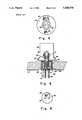
- FIG. 1is an elevation view, in cross section, illustrating a gas generator such as that disclosed in U.S. Pat. No. 4,943,086 and incorporating a squib of the pin type;
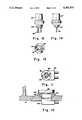
- FIG. 2is an elevation view, in cross section, illustrating a gas generator such as that disclosed in Adams et al. U.S. Pat. No. 4,561,675 and incorporating a squib of the pig tail type;
- FIG. 3is an elevation view, in cross section, of an igniter system containing a squib of the pin type that may be employed in the gas generator of FIG. 1, which igniter system is commercially available from Daavey Bickford Siege Social, 37, Rue Saint-Maur, 76000 Rouen, France;
- FIG. 4shows a bottom view of the igniter system of FIG. 3
- FIG. 5is an elevation view, partly in section, showing the squib of FIG. 3 and an enlarged fragment of the base of the generator of FIG. 1 with the universal squib connector positioned in and securely retained in a socket in the generator base, and with fig tail conductors or lead wires extending downwardly from the connector;
- FIG. 6is a top view of the universal squib connector showing the openings for receiving the mating pins of the squib of FIG. 5;
- FIG. 7is an elevation view, partly in section, illustrating a modification of the universal squib connector of FIG. 5 for enabling the pig tail conductors or lead wires to extend at a right angle to the connector parallel to the bottom surface of the generator base, and incorporating locking and anti-rotation features;
- FIG. 8is a top view of the connector of FIG. 7 showing an anti-rotation rib and also the openings into which the pins of the squib are received;
- FIG. 9is a cross sectional elevational view of the universal squib connector modification taken along the lines 9--9 of FIG. 7;
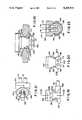
- FIG. 10is an elevation view, partly in section illustrating a modification of the universal squib connector of FIG. 7;
- FIG. 11is a top view of the universal squib connector of FIG. 10;
- FIGS. 12, 13 and 14are elevation, side and bottom views, respectively , illustrating a modification of the base of the squib used with the universal squib connector of FIGS. 10 and 11;
- FIG. 15is a fragmented elevation view, partly in section, illustrating another modification of the universal squib connector incorporating locking and anti-rotation features, positioned in and securely retained in a socket of the gas generator base, with pig tail connectors extending parallel to the bottom surface of the generator base;
- FIGS. 17 and 18are elevation, side and bottom views, respectively, illustrating a modification of the base of the squib used with the universal squib connector of FIG. 15;
- FIGS. 19, 20 and 21are elevation, side and top views, respectively, of the universal squib connector of FIG. 15;
- FIG. 22is a cross sectional view taken on the lines 22--22 of FIG. 19;
- FIG. 23is a cross sectional view taken on the lines 23--23 of FIG. 20.
- FIG. 24is an enlarged fragemented cross sectional view of one of a plurality of axially extending elongated sharp edged projections or ribs that are provided on the exterior surface of the universal squib connector of FIG. 15 for taking up slack or tolerance in making the connector fit tightly in the socket of the gas generator.
- FIG. 1 of the drawingsthere is shown at 10 a gas generator which is operable when initiated to provide gas for rapidly inflating a vehicle inflatable air bag.
- the generator 10has a generally cylindrical outline and includes a housing structure 12 comprising two components. These structural components comprise a lower or base component 14 and an upper component 16. Each of the component 14 and 16 may be composed of aluminum to minimize the weight of the generator. Components 14 and 16 are joined by two concentric inertia welds indicated at 18 amd 20 to form te housing structure 12. Welds 18 and 20 are performed simultaneously in a single inertia welding operation.
- the base 14may be formed by forging or impact extruding and includes a cylindrical wall 22 which is mated with and is inertia welded to a circular surface 24 on the upper structural component 16 at the weld 18 to define a combustion chamber 26.
- the upper component 16may be formed by forming or impact extruding and includes a cylindrical wall 28 which is concentric with wall 22 and is mated with a mating surface 30 of the base 14 and is welded by weld 20 to define an annular diffuser chamber 32 between the inner and outer walls 22 and 28, respectively, in which the gas generated by generator 10 is cooled and filtered.
- the base component 14includes, centrally thereof, an inwardly protruding post 34 on which an electric igniter system 36, including a squib 37 therein, is mounted, being retained thereon by a portion 38 of the post 34 which is crimped over a flange 40 on the lower end 42 of igniter system 36. Protruding downwardly through a central aperture 44 of the post 34 are spaced parallel pins 46 comprising electric input terminals of the squib 37 of the igniter system 36.
- an ignition bead 48 of the squib 37comprising a priming charge that is positioned in firing relation to a bridge wire (not shown).
- pyrotechnic material 50Surrounding the ignition bead 48 is pyrotechnic material 50 which may comprise QVB powder (quick velocity burn).
- Igniter system 36includes an outer shell 52 that may be made of steel.
- An insert 54which also may be made of steel is assembled in closing and sealing relation to the lower end of shell 52, being laser welded to the flared lower end 56 thereof, as illustrated at 58.
- a rubber inner seal 60is provided on the inner wall of shell 52.
- a plastic member 62having a centrally located aperture 64 therein, and which is molded to the insert 54, extends between the upper end of insert 54 and the ignition bead 48.
- An aperture 66is provided in the insert 54. Inwardly thereof aperture 66 is closed in sealing relation by a member 70 in the form of a glass plug that forms a glass to metal seal with the insert 54 and also with pins 46 that extend through member 70 to the bridge wire provided in the aperture 64 of plastic member 62.
- the ignition bead 48Upon an initiating flow of electric current through the bridge wire of the squib 37, the ignition bead 48 is ignited and fires directly into the pyrotechnic material 50.
- Outer shell 52is serrated, as illustraded at 72, for explosive separation thereby allowing the resulting hot ignition gases to expand and flow into the combustion chamber 26.
- pellets 74 of the gas generant compositionContained within the combustion chamber 26, as shown in FIG. 1, are uniformly distributed pellets 74 of the gas generant composition, which pellets are held in place by retainer disk 75 and are ignited for the production of inflation gas by the flow therein of ignition gases from the igniter system 36.
- a plurality of aperture 76are provided in the inner cylinder 22 around the circumference thereof for distributing the flow of gas generated in the combustion chamber 26 into the diffuser chamber 32.
- An aluminum foil or other suitable materialmay be provided on the inner surface of cylinder 22 for hermetically sealing the combustion chamber 26 against moisture and other constituents of the environment to which the generator 10 is exposed that could tend to be deleterious to the desired operability thereof.
- a generally cylindrical cooling and filtering screen 78is positioned in the combustion chamber 26.
- the screen 78may be positioned adjacent the aforementioned aluminum foil that is provided for forming a hermetical seal for the combustion chamber 26, and provides cooling and filtering of the generated gas prior to entry thereof into the diffuser chamber 32.
- a plurality of apertures or ports 80that are spaced around the circumference thereof and through which the generated gas is directed into an air bag (not shown) that is to be inflated.
- An auto ignition device 82is disposed in a cavity 84 that is provided in the inner wall of the upper component 16, centrally thereof.
- the purpose of the auto ignition deviceis to ignite the gas generating pellets 74 and the pyrotechnic material 50, in the event of a fire while the gas generator 10 is being shipped, in storage, or installed in a vehicle, at a temperature which is lower than the ignition temperatures of pellets 72 and material 50 but which is substantially higher than the ambient temperature range to which the generator 10 normally is subjected. This prevents ignition of the pyrotechnic material 50 and 72 when, due to a fire, the generator housing is at a temperature at which the aluminum of the housing has degraded and may tend to rupture or burst.
- the auto ignition device 82includes a suitable pyrotechnic material 86, a suitable gun powder, for example, enclosed in a pouch 88 shaped to fit the cavity 84 and covered by a suitable foil (not shown) such as aluminum foil.
- the structural component or base 14includes an attachment flange 90 having a plurality of apertures 92 therein spaced circumferentially thereabout for the attachment of the generator 10 to a vehicle the occupants of which are to be protected.
- the attachment flange 90may be of any suitable configuration depending upon the interface requirements with the vehicle.
- Functioning of the gas generator 10begins with an electrical signal from a collision sensor (not shown) to the igniter system 36.
- the resulting heating of the bridge wire (not shown) to the point of disintegrationfires the ignition bead 48 igniting the pyrotechnic material 50.
- the material 50burns and the hot gases produced thereby tend to expand, building up pressure until the outer shell 52 of the igniter system 36 explosively separates to allow the hot gases to flow into combustion chamber 26 to ignite the gas generant pellets 74 therein.
- the gas produced by ignition of the pellets 74flow through the cooling and filtering screen 76 where they are initially cooled and filtered after which they burst through the combustion chamber aluminum foil seal and pass through the apertures 76 into the diffuser chamber 32.
- the generated gasesare cooled and filtered after which they flow out of the apertures or ports 80 into an air bag for the inflation thereof.
- the gas generator 94 illustrated in FIG. 2differs in a number of respects from that shown in FIG. 1 including the addition of a third internal cylinder 96 which separates the combustion chamber 98 from an ignition chamber 100 in which an electric igniter or squib 102 is contained. Additionally, as shown, the squib 102 is of the pig tail type. A wire connector shown at 99 connects input conductors 101 and 103 from the squib 102 to the electrical system of the vehicle.
- FIGS. 5 and 6One embodiment of a universal squib connector incorporating EMI/RFI protection, according to the invention for providing a permanent pig tail connection to a pin type electric initiator or squib, is illustrated in FIGS. 5 and 6.
- a universal squib connector 104includes two or four contacts or terminals 106 and 108 that mate with a respectively associated one of the protruding pins 46 of the squib 37 of the igniter system 36 of FIG. 1.
- Automotive lead wires 110 and 112are attached to the terminals 106 and 108, respectively. Such attachment may be by soldering, crimping and/or welding, as indicated at 114 and 116.
- Each terminal and associated lead wire attachment 106, 114 and 108, 116is positioned and retained in a separate aperture or hole 118 and 120, respectively, in a ferrite bead 122, with the spacing between the holes being such as to allow mating engagement of the pins 46 with the terminals 106 and 108, as shown.
- the terminals 106 and 108, the lead wire attachments 114 and 116, and the ferrite bead 122(which provides EMI/RFI protection) are encapsulated in electrical insulating material 124 which may comprise a suitable plastic with the terminals 106 and 108 physically and electrically isolated from each other.
- the ferrite bead 122does not provide an electrically conductive path between the two terminals 106 and 108 or the two terminals 106 and 108 and the insulating material 124.
- the ferrite bead 122provides protection from electromagnetic and radio frequency interference that may tend to be extraneously induced in the terminals 106 and 108.
- the universal squib connector 104may be firmly secured in a socket or cavity 126 that is provided in the base component 14 of the generator 10 by any suitable means which, as shown in FIG. 5, may comprise a crimp 128.
- FIGS. 7, 8 and 9Another embodiment of the universal squib connector according to the invention, indicated by the reference numeral 130, is illustrated in FIGS. 7, 8 and 9.
- the universal squib connector 130differs from that shown in FIGS. 5 and 6 in several respects. Specifically, as shown, the length of the connector 130 is extended sufficiently to allow the automotive lead wires 110 and 112 to be bent through an angle of 90° to run parallel and in close proximity to the base component 14 of the gas generator 10. To this end, the connector 130 includes a portion 132 at the outer end that extends at a right angle thereto for determining the direction in which the lead wires emerge therefrom. In addition, the portion 132 is provided with an anti-rotation rib 134.
- the rib 134in cooperation with a cutout 136 in the outer end of socket 126 of base component 14, permits insertion of the connector 130 into the socket 126 in cooperative engagement with the pins 46 of the squib 37 in one angular position only, thereby determining the orientation of the universal squib connector 130 with respect to the base component 14 and squib 37 of the gas generator 10. To that end the cutout 136 matches the geometrical configuration of the rib 134. Additionally, the rib 134 prevents rotation of the squib 37 and of connector 104 in socket 126 relatively to the base component 14.
- an expansible locking means or ring 138that may be made of steel or other suitable material and is positioned in a groove 140 in the outer surface of the universal squib connector 130.
- the locking ring 138expands out of the groove 140 into locking relation with a groove 142 provided on the interior wall of the socket 126 thereby to retain the connector 130 in the socket 126 with each of the terminals 106 and 108 in engagement with a respectively associated pin 46 of the squib 37.
- a rubber sealing ring 144 positioned in a groove 146 on the outer surface of the connector 130may be provided for sealing the terminals 106 and 108 from the external environment.
- FIGS. 10 and 11A further embodiment of the universal squib connector according to the invention, indicated by the reference numeral 148, is illustrated in FIGS. 10 and 11.
- the connector 148differs from the connector 130 shown in FIGS. 7 and 8 in that the anti-rotation rib 136 has been eliminated and a generally rectangular cavity or groove 150 has been provided instead. Elimination of the anti-rotation rib 136 on the universal squib connector makes unnecessary the formation of the cutout 136 in the wall of the socket 126 in the base component 14 of the gas generator 10.
- Cavity 150adjoins in a symmetrical manner the apertures or holes 118 and 120 that receive the mating pins 46 of the squib of the gas generator 10.
- the squib provided for use with the universal squib connector 148includes a projection or projecting part 152 on the base thereof.
- the projection 152extends in the direction of the pins 46, being positioned symmetrically with respect thereto, and is disposed to fit into the groove 150.
- the contour or configuration of the projection 152matches that of the cavity 150, being slightly smaller, however, to allow easy insertion of the projection 152 into the cavity 150 as the universal squib connector 148 is positioned in the socket 126 of the base component 14 of the gas generator 10.
- the projection 152permits such positioning of the connector 148 in socket 126 in two angular positions that are spaced 180° apart.
- the contours of the cavity 150 and the projection 152may be such that there is only one angular position in which the projection 152 will fit in the cavity 150, and hence, only one angular position in which the universal squib connector 148 properly may be fully inserted into the socket 126. Whether arranged to permit one or two angular positions, and hence, predetermined oriented positions of the universal squib connector squib 148 with respect to the squib 37' and gas generator 10, it will be apparent that the cavity 150 and projection 152 preclude any relative angular movement between the squib 37' and the universal squib connector 148.
- a first circumferential groove 154on the outer cylindrical surface of the connector 148 and an expansible locking ring 156 that may be made of steel or other suitable material, which locking ring may be positioned in the groove 154.
- the locking ring 156expands out of the groove 154 into locking relation with a second circumferential groove 158 that may be provided on the interior wall of the socket 126 thereby to retain the connector 148 in the socket 126 with each of the terminals 106 and 108 in engagement with a respectively associated pin 46 of the squib 37'.
- Such cooperative relation of locking ring 156 and groove 158 on the interior wall of the socket 126may be substantially identical to that of the locking ring 138 and groove 140 as shown in FIG. 7.
- a rubber sealing ring similar to the sealing ring 144 of FIG. 7may be positioned in a groove on the outer cylindrical surface of the universal squib connector 148 for sealing the terminals 106 and 108 from the external environment.
- the cavity 150 provided in the universal squib connector 148may be disposed non-symmetrically, if desired, with respect to the holes 118 and 120 that receive the protruding pins of the squib 37'.
- the projection 152 on the base of the squib 37'would be similarly positioned non-symmetrically with respect to the protruding pins 46, with the contour of the projection 152 matching that of the cavity 150 in the universal squib connector 148.
- the cavity 150may be positioned in either contact or non-contact relation with the holes 118 and 120 of the universal squib connector, and similarly, that the projection 152 on the squib may be positioned in either contact with or non-contact with the protruding pins 46.
- the terms “adjoin” and “adjoining”are used in a broad sense to mean either “lying next to and in contact” or “lying next to and not in contact.”
- FIGS. 15-24Another and preferred embodiment of a universal squib connector incorporating EMI/RFI protection, according to the invention, indicated by the reference numeral 160, is illustrated in FIGS. 15-24.
- the length of the universal squib connector 160is sufficient to allow the automotive lead wires 110 and 112 to be bent through an angle of 90° to run parallel to and in close proximity to the base 14 of the gas generator 10.
- the universal squib connector 160differs, however, from the connectors 130 and 148 in several important respects, foremost of which is that the connector 160 is a single piece universal squib connector.
- a separate expansible locking meanssuch as the ring 138 and the ring 156 which are associated with the connectors 130 and 148, respectively, is not required for firmly securing the universal squib connector 160 in the generator socket 126.
- the connector 160differs, additionally, from the other universal squib connectors disclosed herein, including the connector 104 of FIG. 5, in that there is only one angular position in which the connector 160 properly may be fully inserted into the socket 126.
- a further difference in the connector 160 over the connectors 104, 130 and 148is the provision of a structural configuration, as hereinafter described, that facilitates the execution of a "pull test" for providing assurance that, when inserted in the generator socket 126, the connector 160 is firmly secured therein.
- the means provided in the preferred embodiment of the invention for securely retaining the universal squib connector 160 in the socket 126 of the gas generatorcomprises a locking means 162 including a first latch member 164 provided on one side of the connector 160 and a second latch member 166 provided on the other side thereof.
- Each of the latch members 165 and 166may be molded in electrical insulating material 168 in which the terminals 118 and 120 of the connector 160 are encapsulated, and comprises an integrally formed outwardly and downwardly extending flexible member.
- the electrical insulating material 168may comprise a plastic material that is identical to the material 124 in which the universal squib connectors 104, 130 and 148 are encapsulated.
- each of the latch members 164 and 166shapes into a circumferential groove of the cylindrical wall 127 of the generator socket 126.
- each of the flexible members 164 and 166is compressed against an associated recessed wall portion 170 and 172, respectively, of the connector 160.
- the compressive forceis released and each of the latch members 164 and 166 moves outwardly into a respectively circumferential groove 174 that is provided in the wall 127 of the socket 126, as indicated in FIG. 15.
- Groove 174may have a rectangular cross section, or if desired, a cross section of triangular shape to match the outwardly flared configuration that the latch members 164 and 166 normally tend to assume.
- the locking means 162comprising latch members 164 and 166 formed in the encapsulating material 168 of the connector 160 and the respectively associated groove 174, the connector 160 is fixedly secured in the generator socket 126 simply by the insertion of connector 160 therein, in the proper angular position as described hereinafter.
- a T-shaped cavity 178in the top portion of connector 160, as best seen in FIG. 21.
- Cavity 178adjoins in a symmetrical manner the apertures or holes 118 and 120 that receive the mating pins 46 of the squib of the gas generator 10.
- the squib provided for use with the universal squib connector 160includes a T-shaped projection or boss 180 on the base thereof.
- the projection 180extends in the direction of the pins 46 of the squib 37", being positioned symmetrically with respect thereto, and fits into the cavity 178 in the connector 160.
- the T-shape of the projection 180matches that of the cavity 178, being slightly smaller, however, to allow easy insertion and snug fit of the projection 180 into the cavity 178 as the universal squib connector is inserted in the generator socket 126.
- ribs 182, 184, 186 and 188are provided around the cylindrical surface of the connector 160 at the lower portion thereof, being molded therein.
- the ribs 182, 184, 186 and 188are uniformly spaced around the connector 160.
- Two of the ribs 182 and 184are shorter in length than the other two, 186 and 188, with the axial positions of all of the ribs being such, however, that they all engage the wall 127 of the generator socket 126 at substantially the same time and allow the connector 160 to be inserted therein in concentric relation therewith.
- the electrically insulating plastic material 168 in which the connector 160 is encapsulatedis so configured, as best seen in FIGS. 15, 19 and 20, to facilitate gripping thereof by automated equipment performing the test.
- the connector 160includes a connector portion 190 that abuts against the bottom surface of the generator base member 14 when the connector 160 is fully and properly inserted in the socket 126, which connector portion 190 extends at a right angle to the connector 160 and in the direction of the electrical input connectors 110 and 112.
- Triangularly shaped edges 192 and 194 on the connector portion 190makes gripping of the connector 160 more convenient in the performance of the pull test, as does also a connector portion 196 provided on the other side of the connector 160 which portion 190 extends away from the electrical input connectors 110 and 112, as shown in FIGS. 19 and 21.
- the connector portion 196is spaced somewhat from the base 14 of the generator 10 when the connector 160 is fully properly inserted in the generator socket 126. This spacing contributes also to facilitating the pull test.
- a universal squib connector 104, 130, 148 or 160may be provided separately from the gas generator 10 with which it is to be associated and which incorporates a squib 37, 37' or 37" having protruding pins 46.
- Such vehicle manufacturermay then assemble the appropriate universal squib connector to the generator 10, inserting it in the socket 126 with the terminals 106 and 108 thereof in proper engagement with the pins 46 of the squib 37 and providing a crimp 128 to firmly secure the connector in place if of the first embodiment illustrated and designated by reference numeral 104; and if of an alternative embodiment designated 130 or 148, simply inserting the connector in the socket 126 and locking it in place by means of the locking ring 138 or 156 and the associated groove in the wall of socket 126 in the case of the embodiments designated 130 and 148.
- the alternative and preferred embodiment designated 160is a single piece universal squib connector and requires no locking means separate from the connector 160 to retain it in place once the connector has been fully and properly inserted in the generator socket 126.
- the universal squib connectormay be assembled with an associated gas generator 10 incorporating an appropriate squib of the pin type by the manufacturer of the collision protection system, with the universal squib connector 104, 130, 148 or 160 firmly secured in place in the socket 126 of the generator 10 and with the terminals 106 and 108 of the associated squib 37, 37' or 37".
- a universal squid connector for vehicle driver and passenger air bag collision protection systemsthat enables the use of a single configuration of gas generator and a single configuration of squib for the igniter system of the gas generator while providing the necessary and desirable EMI/RFI protection and the advantages realizable from both pin type and pig tail type connection of the collision sensor input conductors or lead wires to the squib and also the electrical system for the vehicle according to the preferences of individual vehicle manufacturers.
- the universal squib connectoris characterized in comprising an integral connector and connector lock containing, that is, incorporating EMI/RFI protection in a region surrounding two electrical terminals that are configured to mate with and make electrical engagement with the protruding pins of a pin type electric initiator of squib.
- a feature of the connectoris that the terminals are protected from corrosion tending to result from exposure to the environment in which the connector is expected to be operative over long periods of time, with the terminals physically and electrically isolated from each other.
Landscapes
- Engineering & Computer Science (AREA)
- General Engineering & Computer Science (AREA)
- Physics & Mathematics (AREA)
- Fluid Mechanics (AREA)
- Mechanical Engineering (AREA)
- Air Bags (AREA)
Abstract
Description
Claims (4)
Priority Applications (5)
| Application Number | Priority Date | Filing Date | Title |
|---|---|---|---|
| US07/837,080US5200574A (en) | 1991-04-05 | 1992-02-24 | Universal squib connector |
| JP4082287AJP2896262B2 (en) | 1991-04-05 | 1992-04-03 | Flexible ignition device connecting device and gas generating device using the same |
| DE69222802TDE69222802T2 (en) | 1991-04-05 | 1992-04-03 | Universal connector for detonator |
| EP92302968AEP0512682B1 (en) | 1991-04-05 | 1992-04-03 | Universal squib connector |
| ES92302968TES2109980T3 (en) | 1991-04-05 | 1992-04-03 | UNIVERSAL CONNECTION FOR DETONATOR CAPSULE. |
Applications Claiming Priority (2)
| Application Number | Priority Date | Filing Date | Title |
|---|---|---|---|
| US07/680,979US5241910A (en) | 1991-04-05 | 1991-04-05 | Universal squib connector for a gas generator |
| US07/837,080US5200574A (en) | 1991-04-05 | 1992-02-24 | Universal squib connector |
Related Parent Applications (1)
| Application Number | Title | Priority Date | Filing Date |
|---|---|---|---|
| US07/680,979Continuation-In-PartUS5241910A (en) | 1991-04-05 | 1991-04-05 | Universal squib connector for a gas generator |
Publications (1)
| Publication Number | Publication Date |
|---|---|
| US5200574Atrue US5200574A (en) | 1993-04-06 |
Family
ID=27102562
Family Applications (1)
| Application Number | Title | Priority Date | Filing Date |
|---|---|---|---|
| US07/837,080Expired - LifetimeUS5200574A (en) | 1991-04-05 | 1992-02-24 | Universal squib connector |
Country Status (5)
| Country | Link |
|---|---|
| US (1) | US5200574A (en) |
| EP (1) | EP0512682B1 (en) |
| JP (1) | JP2896262B2 (en) |
| DE (1) | DE69222802T2 (en) |
| ES (1) | ES2109980T3 (en) |
Cited By (47)
| Publication number | Priority date | Publication date | Assignee | Title |
|---|---|---|---|---|
| US5404263A (en)* | 1992-08-27 | 1995-04-04 | Oea, Inc. | All-glass header assembly used in an inflator system |
| US5489220A (en)* | 1992-10-30 | 1996-02-06 | Berg Technology, Inc. | Filter connector arrangement having a ferrite barrel with a rectangular bore |
| US5529338A (en)* | 1994-07-20 | 1996-06-25 | Methode Electronics, Inc. | One piece automotive airbag squib connector |
| US5616881A (en)* | 1995-05-30 | 1997-04-01 | Morton International, Inc. | Inflator socket pin collar for integrated circuit initaitor with integral metal oxide varistor for electro-static discharge protections |
| US5648634A (en)* | 1993-10-20 | 1997-07-15 | Quantic Industries, Inc. | Electrical initiator |
| US5672841A (en)* | 1995-12-15 | 1997-09-30 | Morton International, Inc. | Inflator initiator with zener diode electrostatic discharge protection |
| US5709724A (en)* | 1994-08-04 | 1998-01-20 | Coors Ceramics Company | Process for fabricating a hermetic glass-to-metal seal |
| US5728964A (en)* | 1993-10-20 | 1998-03-17 | Quantic Industries, Inc. | Electrical initiator |
| US5746618A (en)* | 1995-07-14 | 1998-05-05 | Augat Inc. | Squib connector for automotive air bag assembly |
| US5882224A (en)* | 1996-08-28 | 1999-03-16 | Thomas & Betts International, Inc. | Squib connector socker assembly having shorting clip for automotive air bags |
| US5932832A (en)* | 1996-04-15 | 1999-08-03 | Autoliv Asp, Inc. | High pressure resistant initiator with integral metal oxide varistor for electro-static discharge protection |
| US5944545A (en)* | 1997-08-29 | 1999-08-31 | Talley Defense Systems, Inc. | Single pin coaxial initiator, retainer and connector and method of operation |
| US5993230A (en)* | 1996-08-12 | 1999-11-30 | Thomas & Betts International, Inc. | Orientationless squib connector assembly for automotive air bag assemblies |
| US6152775A (en)* | 1998-12-07 | 2000-11-28 | Framatome Connectors Interlock, Inc. | Filtered electrical connector with multiple ferrite members |
| US6227115B1 (en)* | 1996-03-19 | 2001-05-08 | Siemens Aktiengesellschaft | Ignition device for tripping a passenger restraint device in a motor vehicle |
| US6234843B1 (en) | 1998-12-07 | 2001-05-22 | Framatome Connectors Interlock Inc. | Low profile filter connector with ferrite |
| US6250952B1 (en) | 1997-08-08 | 2001-06-26 | The Whitaker Corporation | Air bag connector |
| US6274252B1 (en) | 1994-08-04 | 2001-08-14 | Coors Ceramics Company | Hermetic glass-to-metal seal useful in headers for airbags |
| US6276953B1 (en) | 1997-12-04 | 2001-08-21 | Thoma & Betts International, Inc. | Orientationless squib connector assembly for automotive air bag assemblies |
| US6328337B1 (en) | 1997-08-12 | 2001-12-11 | Daicel Chemical Industries, Ltd. | Air bag gas generator and air bag system |
| US6398590B2 (en) | 2000-07-11 | 2002-06-04 | Tyco Electronics Corporation | Nonpolarized electrical connector assembly especially for use as automotive squib connector |
| US6422146B1 (en)* | 1999-08-27 | 2002-07-23 | Trw Airbag Systems Gmbh & Co. Kg | Igniter unit for an inflator |
| US6454306B1 (en)* | 2000-08-01 | 2002-09-24 | Trw Inc. | Gas generator for seat belt pretensioner |
| US6460883B1 (en)* | 1998-09-28 | 2002-10-08 | Daicel Chemical Industries, Ltd. | Air bag gas generator and air bag apparatus |
| US6477957B2 (en)* | 2000-06-02 | 2002-11-12 | Hirschmann Austria Gmbh | Ignition device for a safety system |
| US20030005843A1 (en)* | 2001-07-05 | 2003-01-09 | Special Devices, Inc. | Pyrotechnic initiator with on-board control circuitry |
| US6591754B1 (en)* | 1999-08-25 | 2003-07-15 | Daimlerchrysler Ag | Pyrotechnical ignition system with integrated ignition circuit |
| US6609931B2 (en) | 2001-10-25 | 2003-08-26 | Tyco Electronics Corp. | Orientationless squib connector assembly |
| US6695345B2 (en) | 1996-04-08 | 2004-02-24 | Daicel Chemical Industries, Ltd. | Airbag inflator and an airbag apparatus |
| US6718884B1 (en)* | 1999-09-27 | 2004-04-13 | Daicel Chemical Industries, Ltd. | Initiator assembly |
| US20040097116A1 (en)* | 2002-11-18 | 2004-05-20 | J. S. T. Mfg. Co., Ltd. | Shunt for squib |
| US20040207188A1 (en)* | 2002-12-09 | 2004-10-21 | Naoki Matsuda | Gas generator for air bag |
| US6904846B2 (en)* | 2001-01-13 | 2005-06-14 | Hirschmann Austria Gmbh | Ignition device for a safety system |
| US20050126416A1 (en)* | 2003-12-11 | 2005-06-16 | Marcus Clark | Snap-locking initiator assemblies for inflator devices |
| US6936303B1 (en)* | 1999-10-28 | 2005-08-30 | Daicel Chemical Industries, Ltd. | Electric type initiator and gas generator |
| US20050250350A1 (en)* | 2000-06-08 | 2005-11-10 | Yoshihiro Nakashima | Gas generator for air bag and air bag apparatus |
| US6997750B2 (en) | 2003-07-23 | 2006-02-14 | Fci Americas Technology, Inc. | Electrical connector contact |
| US20060084314A1 (en)* | 2004-10-15 | 2006-04-20 | Eiichiro Takizawa | Connector housing and electrical connector |
| US20060207469A1 (en)* | 2005-03-03 | 2006-09-21 | Schott Ag | Ignition device for a passenger protection device of a motor vehicle |
| US20070266880A1 (en)* | 2006-05-16 | 2007-11-22 | Takata Corporation | Initiator, inflator, and airbag apparatus |
| US20080026610A1 (en)* | 2006-06-22 | 2008-01-31 | Watlow Electric Manufacturing Co. | Sensor adaptor circuit housing assembly and method of manufacturing thereof |
| US20080042893A1 (en)* | 2006-08-15 | 2008-02-21 | General Dynamics Advanced Information Systems, Inc. | Methods for two-dimensional autofocus in high resolution radar systems |
| US20080063993A1 (en)* | 2006-08-28 | 2008-03-13 | Nobuyuki Katsuda | Gas generator |
| US7665890B2 (en) | 2006-06-22 | 2010-02-23 | Watlow Electric Manufacturing Company | Temperature sensor assembly and method of manufacturing thereof |
| US8100043B1 (en)* | 2008-03-28 | 2012-01-24 | Reynolds Systems, Inc. | Detonator cartridge and methods of use |
| US8661985B2 (en) | 2012-04-18 | 2014-03-04 | Autoliv Asp, Inc. | Low-profile igniter assemblies adapted for use with inflatable airbag systems |
| US20190024893A1 (en)* | 2017-05-16 | 2019-01-24 | Malcolm Gorst | Universal housing for a hot surface igniter |
Families Citing this family (17)
| Publication number | Priority date | Publication date | Assignee | Title |
|---|---|---|---|---|
| US5733135A (en)* | 1995-12-06 | 1998-03-31 | Trw Inc. | Air bag inflator assembly with shorting clip |
| FR2747772B1 (en)* | 1996-04-22 | 1999-08-06 | Livbag Snc | SELF-LOCKING TWO-WIRE INITIATOR FOR PYROTECHNIC GAS GENERATORS |
| DE19627635C1 (en)* | 1996-07-09 | 1997-12-04 | Siemens Ag | Primer plug connector |
| DE29612781U1 (en)* | 1996-07-23 | 1996-11-21 | Trw Occupant Restraint Systems Gmbh, 73551 Alfdorf | Pyrotechnic linear drive device for a belt tensioner |
| FR2753014B1 (en)* | 1996-09-02 | 1998-11-20 | Axon Cable Sa | TERMINATION OF ELECTRIC CABLE PROVIDED WITH A FILTER |
| DE19654314A1 (en)* | 1996-12-24 | 1998-06-25 | Dynamit Nobel Ag | Ignition element, in particular for pyrotechnic mixtures |
| FR2760525B1 (en) | 1997-03-07 | 1999-04-16 | Livbag Snc | ELECTRO-PYROTECHNIC INITIATOR BUILT AROUND A FULL PRINTED CIRCUIT |
| DE20112834U1 (en)* | 2001-08-02 | 2001-12-13 | TRW Occupant Restraint Systems GmbH & Co. KG, 73553 Alfdorf | Igniter for a gas generator |
| US6820556B1 (en) | 2001-11-21 | 2004-11-23 | Daicel Chemical Industries, Ltd. | Initiator assembly |
| JP4021178B2 (en)† | 2001-11-21 | 2007-12-12 | ダイセル化学工業株式会社 | Initiator assembly |
| JP4005385B2 (en)* | 2002-02-25 | 2007-11-07 | タイコエレクトロニクスアンプ株式会社 | Ignition device connector assembly and short-circuit assembly |
| CN101365921A (en)* | 2006-01-06 | 2009-02-11 | 日本化药株式会社 | Ignition device, air bag, and gas generator for seat belt pretensioner |
| DE102008025218B3 (en)* | 2008-05-27 | 2009-11-12 | Bayern-Chemie Gesellschaft Für Flugchemische Antriebe Mbh | initiator |
| EP3300960B1 (en) | 2008-09-30 | 2019-11-06 | TRW Airbag Systems GmbH | Gas generator and module having a gas generator |
| JP5162646B2 (en)* | 2010-11-18 | 2013-03-13 | 助川電気工業株式会社 | Induction electromagnetic pump for molten metal |
| DE102019132459A1 (en)* | 2019-11-29 | 2021-06-02 | Zf Airbag Germany Gmbh | GAS GENERATOR FOR A VEHICLE SAFETY SYSTEM, METHOD FOR ELECTRICALLY CONTACTING A GAS GENERATOR |
| CZ2023490A3 (en)* | 2023-12-15 | 2025-03-05 | Kayaku Safety Systems Europe a.s. | Squib-based heat generator |
Citations (15)
| Publication number | Priority date | Publication date | Assignee | Title |
|---|---|---|---|---|
| US3093433A (en)* | 1960-12-27 | 1963-06-11 | Underwriters Safety Device Co | Wire terminals and lead connector devices |
| US3370140A (en)* | 1966-11-16 | 1968-02-20 | Robert E. Betts | Electro-magnetic radiation proof plug and receptacle |
| US4319800A (en)* | 1980-03-07 | 1982-03-16 | Triangle Pwc, Inc. | Barrier for molded female power cord connector bodies |
| US4374605A (en)* | 1979-09-03 | 1983-02-22 | Aktiebolaget Bofors | An assembly of an electrical connector and pyrotechnic igniter |
| US4378738A (en)* | 1979-12-19 | 1983-04-05 | Proctor Paul W | Electromagnetic and electrostatic insensitive blasting caps, squibs and detonators |
| US4386818A (en)* | 1981-04-27 | 1983-06-07 | Amp Incorporated | Polarity indicating connector for battery jumper cables |
| US4519664A (en)* | 1983-02-16 | 1985-05-28 | Elco Corporation | Multipin connector and method of reducing EMI by use thereof |
| US4764129A (en)* | 1984-09-27 | 1988-08-16 | British Telecommunications Plc | Electrical connector assemblies |
| US4881463A (en)* | 1988-02-24 | 1989-11-21 | The State Of Israel, Ministry Of Defence, Israel Military Industries | Electric igniter assembly |
| EP0363724A2 (en)* | 1988-10-11 | 1990-04-18 | Mitsubishi Denki Kabushiki Kaisha | Connector for connecting an electrical circuit |
| US4936788A (en)* | 1989-06-06 | 1990-06-26 | New Chien Lung Ent. Co., Ltd. | Electrical connector |
| US5036768A (en)* | 1990-02-13 | 1991-08-06 | Dow Robert L | Attenuator for dissipating electromagnetic and electrostatic energy |
| US5044981A (en)* | 1990-04-18 | 1991-09-03 | Reliance Comm/Tec Corporation | Snap-on stacking telephone jack |
| US5062367A (en)* | 1988-12-05 | 1991-11-05 | Nippon Koki, Co., Ltd. | Air bag inflation gas generator |
| US5092794A (en)* | 1990-12-24 | 1992-03-03 | Molex Incorporated | Shielded electrical connector |
Family Cites Families (7)
| Publication number | Priority date | Publication date | Assignee | Title |
|---|---|---|---|---|
| US3572247A (en)* | 1968-08-29 | 1971-03-23 | Theodore Warshall | Protective rf attenuator plug for wire-bridge detonators |
| US3735705A (en)* | 1971-07-15 | 1973-05-29 | Amp Inc | Filtered electro-explosive device |
| US4306499A (en)* | 1978-04-03 | 1981-12-22 | Thiokol Corporation | Electric safety squib |
| JPS559301A (en)* | 1978-07-01 | 1980-01-23 | Nissan Motor | Connector for igniter |
| JPH0170291U (en)* | 1987-10-29 | 1989-05-10 | ||
| GB2218698A (en)* | 1988-01-19 | 1989-11-22 | Talley Automotive Prod | Inflator device for deployment of a motor vehicle passenger passive restraint system |
| JPH01148678U (en)* | 1988-04-05 | 1989-10-16 |
- 1992
- 1992-02-24USUS07/837,080patent/US5200574A/ennot_activeExpired - Lifetime
- 1992-04-03ESES92302968Tpatent/ES2109980T3/ennot_activeExpired - Lifetime
- 1992-04-03EPEP92302968Apatent/EP0512682B1/ennot_activeExpired - Lifetime
- 1992-04-03DEDE69222802Tpatent/DE69222802T2/ennot_activeExpired - Fee Related
- 1992-04-03JPJP4082287Apatent/JP2896262B2/ennot_activeExpired - Fee Related
Patent Citations (15)
| Publication number | Priority date | Publication date | Assignee | Title |
|---|---|---|---|---|
| US3093433A (en)* | 1960-12-27 | 1963-06-11 | Underwriters Safety Device Co | Wire terminals and lead connector devices |
| US3370140A (en)* | 1966-11-16 | 1968-02-20 | Robert E. Betts | Electro-magnetic radiation proof plug and receptacle |
| US4374605A (en)* | 1979-09-03 | 1983-02-22 | Aktiebolaget Bofors | An assembly of an electrical connector and pyrotechnic igniter |
| US4378738A (en)* | 1979-12-19 | 1983-04-05 | Proctor Paul W | Electromagnetic and electrostatic insensitive blasting caps, squibs and detonators |
| US4319800A (en)* | 1980-03-07 | 1982-03-16 | Triangle Pwc, Inc. | Barrier for molded female power cord connector bodies |
| US4386818A (en)* | 1981-04-27 | 1983-06-07 | Amp Incorporated | Polarity indicating connector for battery jumper cables |
| US4519664A (en)* | 1983-02-16 | 1985-05-28 | Elco Corporation | Multipin connector and method of reducing EMI by use thereof |
| US4764129A (en)* | 1984-09-27 | 1988-08-16 | British Telecommunications Plc | Electrical connector assemblies |
| US4881463A (en)* | 1988-02-24 | 1989-11-21 | The State Of Israel, Ministry Of Defence, Israel Military Industries | Electric igniter assembly |
| EP0363724A2 (en)* | 1988-10-11 | 1990-04-18 | Mitsubishi Denki Kabushiki Kaisha | Connector for connecting an electrical circuit |
| US5062367A (en)* | 1988-12-05 | 1991-11-05 | Nippon Koki, Co., Ltd. | Air bag inflation gas generator |
| US4936788A (en)* | 1989-06-06 | 1990-06-26 | New Chien Lung Ent. Co., Ltd. | Electrical connector |
| US5036768A (en)* | 1990-02-13 | 1991-08-06 | Dow Robert L | Attenuator for dissipating electromagnetic and electrostatic energy |
| US5044981A (en)* | 1990-04-18 | 1991-09-03 | Reliance Comm/Tec Corporation | Snap-on stacking telephone jack |
| US5092794A (en)* | 1990-12-24 | 1992-03-03 | Molex Incorporated | Shielded electrical connector |
Cited By (72)
| Publication number | Priority date | Publication date | Assignee | Title |
|---|---|---|---|---|
| US5404263A (en)* | 1992-08-27 | 1995-04-04 | Oea, Inc. | All-glass header assembly used in an inflator system |
| US5489220A (en)* | 1992-10-30 | 1996-02-06 | Berg Technology, Inc. | Filter connector arrangement having a ferrite barrel with a rectangular bore |
| US5763814A (en)* | 1993-10-20 | 1998-06-09 | Quanti Industries, Inc. | Electrical initiator |
| US5648634A (en)* | 1993-10-20 | 1997-07-15 | Quantic Industries, Inc. | Electrical initiator |
| US5728964A (en)* | 1993-10-20 | 1998-03-17 | Quantic Industries, Inc. | Electrical initiator |
| US5529338A (en)* | 1994-07-20 | 1996-06-25 | Methode Electronics, Inc. | One piece automotive airbag squib connector |
| US6274252B1 (en) | 1994-08-04 | 2001-08-14 | Coors Ceramics Company | Hermetic glass-to-metal seal useful in headers for airbags |
| US5709724A (en)* | 1994-08-04 | 1998-01-20 | Coors Ceramics Company | Process for fabricating a hermetic glass-to-metal seal |
| US5616881A (en)* | 1995-05-30 | 1997-04-01 | Morton International, Inc. | Inflator socket pin collar for integrated circuit initaitor with integral metal oxide varistor for electro-static discharge protections |
| US5746618A (en)* | 1995-07-14 | 1998-05-05 | Augat Inc. | Squib connector for automotive air bag assembly |
| US5672841A (en)* | 1995-12-15 | 1997-09-30 | Morton International, Inc. | Inflator initiator with zener diode electrostatic discharge protection |
| US6227115B1 (en)* | 1996-03-19 | 2001-05-08 | Siemens Aktiengesellschaft | Ignition device for tripping a passenger restraint device in a motor vehicle |
| US6695345B2 (en) | 1996-04-08 | 2004-02-24 | Daicel Chemical Industries, Ltd. | Airbag inflator and an airbag apparatus |
| US5932832A (en)* | 1996-04-15 | 1999-08-03 | Autoliv Asp, Inc. | High pressure resistant initiator with integral metal oxide varistor for electro-static discharge protection |
| US6203342B1 (en) | 1996-08-12 | 2001-03-20 | Thomas & Betts International, Inc. | Grounding plate for orientationless squib connector assembly for automotive air bag assemblies |
| US5993230A (en)* | 1996-08-12 | 1999-11-30 | Thomas & Betts International, Inc. | Orientationless squib connector assembly for automotive air bag assemblies |
| US5882224A (en)* | 1996-08-28 | 1999-03-16 | Thomas & Betts International, Inc. | Squib connector socker assembly having shorting clip for automotive air bags |
| US6145193A (en)* | 1996-08-28 | 2000-11-14 | Thomas & Betts International, Inc. | Method of forming a squib connector socket assembly having shorting clip for automotive air bags |
| US6250952B1 (en) | 1997-08-08 | 2001-06-26 | The Whitaker Corporation | Air bag connector |
| US6520538B2 (en) | 1997-08-12 | 2003-02-18 | Daicel Chemical Industries, Ltd. | Air bag gas generator and air bag system |
| US6328337B1 (en) | 1997-08-12 | 2001-12-11 | Daicel Chemical Industries, Ltd. | Air bag gas generator and air bag system |
| US5944545A (en)* | 1997-08-29 | 1999-08-31 | Talley Defense Systems, Inc. | Single pin coaxial initiator, retainer and connector and method of operation |
| US6276953B1 (en) | 1997-12-04 | 2001-08-21 | Thoma & Betts International, Inc. | Orientationless squib connector assembly for automotive air bag assemblies |
| US6460883B1 (en)* | 1998-09-28 | 2002-10-08 | Daicel Chemical Industries, Ltd. | Air bag gas generator and air bag apparatus |
| US6152775A (en)* | 1998-12-07 | 2000-11-28 | Framatome Connectors Interlock, Inc. | Filtered electrical connector with multiple ferrite members |
| US6234843B1 (en) | 1998-12-07 | 2001-05-22 | Framatome Connectors Interlock Inc. | Low profile filter connector with ferrite |
| US6591754B1 (en)* | 1999-08-25 | 2003-07-15 | Daimlerchrysler Ag | Pyrotechnical ignition system with integrated ignition circuit |
| US6422146B1 (en)* | 1999-08-27 | 2002-07-23 | Trw Airbag Systems Gmbh & Co. Kg | Igniter unit for an inflator |
| US6718884B1 (en)* | 1999-09-27 | 2004-04-13 | Daicel Chemical Industries, Ltd. | Initiator assembly |
| US6936303B1 (en)* | 1999-10-28 | 2005-08-30 | Daicel Chemical Industries, Ltd. | Electric type initiator and gas generator |
| US6477957B2 (en)* | 2000-06-02 | 2002-11-12 | Hirschmann Austria Gmbh | Ignition device for a safety system |
| US7152874B2 (en)* | 2000-06-08 | 2006-12-26 | Daicel Chemical Industries, Ltd. | Gas generator for air bag and air bag apparatus |
| US20050250350A1 (en)* | 2000-06-08 | 2005-11-10 | Yoshihiro Nakashima | Gas generator for air bag and air bag apparatus |
| US6398590B2 (en) | 2000-07-11 | 2002-06-04 | Tyco Electronics Corporation | Nonpolarized electrical connector assembly especially for use as automotive squib connector |
| US6454306B1 (en)* | 2000-08-01 | 2002-09-24 | Trw Inc. | Gas generator for seat belt pretensioner |
| US6904846B2 (en)* | 2001-01-13 | 2005-06-14 | Hirschmann Austria Gmbh | Ignition device for a safety system |
| WO2003004959A3 (en)* | 2001-07-05 | 2003-10-09 | Special Devices Inc | Pyrotechnic initiator with on-board control circuitry |
| US20030005843A1 (en)* | 2001-07-05 | 2003-01-09 | Special Devices, Inc. | Pyrotechnic initiator with on-board control circuitry |
| US6915744B2 (en)* | 2001-07-05 | 2005-07-12 | Special Devices, Inc. | Pyrotechnic initiator with on-board control circuitry |
| US6609931B2 (en) | 2001-10-25 | 2003-08-26 | Tyco Electronics Corp. | Orientationless squib connector assembly |
| US20040097116A1 (en)* | 2002-11-18 | 2004-05-20 | J. S. T. Mfg. Co., Ltd. | Shunt for squib |
| US6910902B2 (en)* | 2002-11-18 | 2005-06-28 | J. S. T. Mfg. Co., Ltd. | Shunt for squib having an improved securing mechanism |
| US20040207188A1 (en)* | 2002-12-09 | 2004-10-21 | Naoki Matsuda | Gas generator for air bag |
| US7172214B2 (en) | 2002-12-09 | 2007-02-06 | Daicel Chemical Industries, Ltd. | Gas generator for air bag |
| US20080057790A1 (en)* | 2003-07-23 | 2008-03-06 | Fci Americas Technology, Inc. | Electrical connector contact |
| US7303441B2 (en) | 2003-07-23 | 2007-12-04 | Fci Americas Technology, Inc. | Electrical connector contact |
| US7547232B2 (en) | 2003-07-23 | 2009-06-16 | Fci Americas Technology, Inc. | Electrical connector contact |
| US7121892B2 (en) | 2003-07-23 | 2006-10-17 | Fci Americas Technology, Inc. | Electrical connector contact |
| US20060035524A1 (en)* | 2003-07-23 | 2006-02-16 | Fci Americas Technology, Inc. | Electrical connector contact |
| US20070015397A1 (en)* | 2003-07-23 | 2007-01-18 | Fci Americas Technology, Inc. | Electrical connector contact |
| US6997750B2 (en) | 2003-07-23 | 2006-02-14 | Fci Americas Technology, Inc. | Electrical connector contact |
| US7241175B2 (en) | 2003-07-23 | 2007-07-10 | Fci Americas Technology, Inc. | Electrical connector contact |
| US7491100B2 (en) | 2003-07-23 | 2009-02-17 | Fci Americas Technology, Inc. | Electrical connector contact |
| US20080171471A1 (en)* | 2003-07-23 | 2008-07-17 | Fci Americas Technology, Inc. | Electrical connector contact |
| US20050126416A1 (en)* | 2003-12-11 | 2005-06-16 | Marcus Clark | Snap-locking initiator assemblies for inflator devices |
| US7510211B2 (en)* | 2003-12-11 | 2009-03-31 | Autoliv Asp, Inc. | Snap-locking initiator assemblies for inflator devices |
| US20060084314A1 (en)* | 2004-10-15 | 2006-04-20 | Eiichiro Takizawa | Connector housing and electrical connector |
| US7770520B2 (en)* | 2005-03-03 | 2010-08-10 | Schott Ag | Initiation device |
| US20060207469A1 (en)* | 2005-03-03 | 2006-09-21 | Schott Ag | Ignition device for a passenger protection device of a motor vehicle |
| US20070266880A1 (en)* | 2006-05-16 | 2007-11-22 | Takata Corporation | Initiator, inflator, and airbag apparatus |
| US20080026610A1 (en)* | 2006-06-22 | 2008-01-31 | Watlow Electric Manufacturing Co. | Sensor adaptor circuit housing assembly and method of manufacturing thereof |
| US7665890B2 (en) | 2006-06-22 | 2010-02-23 | Watlow Electric Manufacturing Company | Temperature sensor assembly and method of manufacturing thereof |
| US7722362B2 (en) | 2006-06-22 | 2010-05-25 | Watlow Electric Manufacturing Company | Sensor adaptor circuit housing incapsulating connection of an input connector with a wire |
| US20080042893A1 (en)* | 2006-08-15 | 2008-02-21 | General Dynamics Advanced Information Systems, Inc. | Methods for two-dimensional autofocus in high resolution radar systems |
| US7663529B2 (en)* | 2006-08-15 | 2010-02-16 | General Dynamics Advanced Information Systems, Inc. | Methods for two-dimensional autofocus in high resolution radar systems |
| US7614875B2 (en)* | 2006-08-28 | 2009-11-10 | Daicel Chemical Industries, Ltd. | Gas generator |
| US20080063993A1 (en)* | 2006-08-28 | 2008-03-13 | Nobuyuki Katsuda | Gas generator |
| US8100043B1 (en)* | 2008-03-28 | 2012-01-24 | Reynolds Systems, Inc. | Detonator cartridge and methods of use |
| US8210083B1 (en) | 2008-03-28 | 2012-07-03 | Reynolds Systems, Inc. | Detonator cartridge |
| US8661985B2 (en) | 2012-04-18 | 2014-03-04 | Autoliv Asp, Inc. | Low-profile igniter assemblies adapted for use with inflatable airbag systems |
| US20190024893A1 (en)* | 2017-05-16 | 2019-01-24 | Malcolm Gorst | Universal housing for a hot surface igniter |
| US10969110B2 (en)* | 2017-05-16 | 2021-04-06 | Malcolm Gorst | Universal housing for a hot surface igniter |
Also Published As
| Publication number | Publication date |
|---|---|
| DE69222802D1 (en) | 1997-11-27 |
| EP0512682A2 (en) | 1992-11-11 |
| ES2109980T3 (en) | 1998-02-01 |
| JP2896262B2 (en) | 1999-05-31 |
| DE69222802T2 (en) | 1998-02-19 |
| EP0512682A3 (en) | 1994-03-16 |
| EP0512682B1 (en) | 1997-10-22 |
| JPH05105027A (en) | 1993-04-27 |
Similar Documents
| Publication | Publication Date | Title |
|---|---|---|
| US5200574A (en) | Universal squib connector | |
| US5241910A (en) | Universal squib connector for a gas generator | |
| US6009809A (en) | Bridgewire initiator | |
| US5345872A (en) | Igniter | |
| JP2535125B2 (en) | Device for connecting electrical connectors | |
| US6848713B2 (en) | Airbag gas producer | |
| US4358135A (en) | Connector for igniting circuit of priming device | |
| US5616881A (en) | Inflator socket pin collar for integrated circuit initaitor with integral metal oxide varistor for electro-static discharge protections | |
| EP1424249A1 (en) | Gas generator | |
| EP0802092A1 (en) | High pressure resistant initiator with integral metal oxide varistor for electro-static discharge protection | |
| EP1227294A1 (en) | Electric type initiator and pretensioner | |
| US20040166715A1 (en) | Squib connector assembly with CPA | |
| JP2007521181A5 (en) | ||
| EP1591159A1 (en) | Gas producer | |
| JP2007521181A (en) | Electrical connection apparatus and method for airbag inflator | |
| US7125041B2 (en) | Gas generator | |
| US11084454B2 (en) | Igniter support, subassembly, gas generator, and method for manufacturing a gas generator | |
| JP2905758B2 (en) | Ignition device with self-locking two-wire connector for pyrotechnic gas generators | |
| US20050189754A1 (en) | Inflator for an air bag | |
| JP2004513013A (en) | Pyrotechnic starter for high pressure environment | |
| US20200189516A1 (en) | Igniter support, subassembly, gas generator, and process for manufacturing a gas generator | |
| WO2022239790A1 (en) | Igniter assembly and gas generation device | |
| JP2536356Y2 (en) | Igniter for gas generator for airbag deployment | |
| JP2536357Y2 (en) | Ignition structure of igniter in gas generator for airbag deployment | |
| JP2512473Y2 (en) | Igniter |
Legal Events
| Date | Code | Title | Description |
|---|---|---|---|
| AS | Assignment | Owner name:MORTON INTERNATIONAL, INC., A CORP. OF INDIANA, IL Free format text:ASSIGNMENT OF ASSIGNORS INTEREST.;ASSIGNORS:CUNNINGHAM, DONALD J.;ALLARD, JOHN E.;REEL/FRAME:006025/0181;SIGNING DATES FROM 19920213 TO 19920217 Owner name:MORTON INTERNATIONAL, INC., A CORP. OF INDIANA, IL Free format text:ASSIGNMENT OF ASSIGNORS INTEREST.;ASSIGNORS:CHANDLER, VIRGINIA E.;SMITH, BRADLEY W.;MONK, DAVID B.;REEL/FRAME:006025/0187;SIGNING DATES FROM 19920214 TO 19920220 | |
| STCF | Information on status: patent grant | Free format text:PATENTED CASE | |
| CC | Certificate of correction | ||
| FEPP | Fee payment procedure | Free format text:PAYOR NUMBER ASSIGNED (ORIGINAL EVENT CODE: ASPN); ENTITY STATUS OF PATENT OWNER: LARGE ENTITY | |
| FPAY | Fee payment | Year of fee payment:4 | |
| AS | Assignment | Owner name:AUTOLIV ASP, INC, UTAH Free format text:MERGER AND CHANGE OF NAME;ASSIGNOR:MORTON INTERNATIONAL, INC;REEL/FRAME:009866/0350 Effective date:19970429 | |
| FEPP | Fee payment procedure | Free format text:PAYOR NUMBER ASSIGNED (ORIGINAL EVENT CODE: ASPN); ENTITY STATUS OF PATENT OWNER: LARGE ENTITY Free format text:PAYER NUMBER DE-ASSIGNED (ORIGINAL EVENT CODE: RMPN); ENTITY STATUS OF PATENT OWNER: LARGE ENTITY | |
| FEPP | Fee payment procedure | Free format text:PAYER NUMBER DE-ASSIGNED (ORIGINAL EVENT CODE: RMPN); ENTITY STATUS OF PATENT OWNER: LARGE ENTITY Free format text:PAYOR NUMBER ASSIGNED (ORIGINAL EVENT CODE: ASPN); ENTITY STATUS OF PATENT OWNER: LARGE ENTITY | |
| FEPP | Fee payment procedure | Free format text:PAYER NUMBER DE-ASSIGNED (ORIGINAL EVENT CODE: RMPN); ENTITY STATUS OF PATENT OWNER: LARGE ENTITY | |
| FPAY | Fee payment | Year of fee payment:8 | |
| FPAY | Fee payment | Year of fee payment:12 |