US5199436A - Radiation detector having improved accuracy - Google Patents
Radiation detector having improved accuracyDownload PDFInfo
- Publication number
- US5199436A US5199436AUS07/646,855US64685591AUS5199436AUS 5199436 AUS5199436 AUS 5199436AUS 64685591 AUS64685591 AUS 64685591AUS 5199436 AUS5199436 AUS 5199436A
- Authority
- US
- United States
- Prior art keywords
- temperature
- radiation
- thermopile
- detector
- sensor
- Prior art date
- Legal status (The legal status is an assumption and is not a legal conclusion. Google has not performed a legal analysis and makes no representation as to the accuracy of the status listed.)
- Expired - Lifetime
Links
Images


Classifications
- G—PHYSICS
- G01—MEASURING; TESTING
- G01J—MEASUREMENT OF INTENSITY, VELOCITY, SPECTRAL CONTENT, POLARISATION, PHASE OR PULSE CHARACTERISTICS OF INFRARED, VISIBLE OR ULTRAVIOLET LIGHT; COLORIMETRY; RADIATION PYROMETRY
- G01J5/00—Radiation pyrometry, e.g. infrared or optical thermometry
- G01J5/02—Constructional details
- G01J5/07—Arrangements for adjusting the solid angle of collected radiation, e.g. adjusting or orienting field of view, tracking position or encoding angular position
- G—PHYSICS
- G01—MEASURING; TESTING
- G01J—MEASUREMENT OF INTENSITY, VELOCITY, SPECTRAL CONTENT, POLARISATION, PHASE OR PULSE CHARACTERISTICS OF INFRARED, VISIBLE OR ULTRAVIOLET LIGHT; COLORIMETRY; RADIATION PYROMETRY
- G01J5/00—Radiation pyrometry, e.g. infrared or optical thermometry
- G01J5/02—Constructional details
- G01J5/021—Probe covers for thermometers, e.g. tympanic thermometers; Containers for probe covers; Disposable probes
- G—PHYSICS
- G01—MEASURING; TESTING
- G01J—MEASUREMENT OF INTENSITY, VELOCITY, SPECTRAL CONTENT, POLARISATION, PHASE OR PULSE CHARACTERISTICS OF INFRARED, VISIBLE OR ULTRAVIOLET LIGHT; COLORIMETRY; RADIATION PYROMETRY
- G01J5/00—Radiation pyrometry, e.g. infrared or optical thermometry
- G01J5/02—Constructional details
- G01J5/026—Control of working procedures of a pyrometer, other than calibration; Bandwidth calculation; Gain control
- G—PHYSICS
- G01—MEASURING; TESTING
- G01J—MEASUREMENT OF INTENSITY, VELOCITY, SPECTRAL CONTENT, POLARISATION, PHASE OR PULSE CHARACTERISTICS OF INFRARED, VISIBLE OR ULTRAVIOLET LIGHT; COLORIMETRY; RADIATION PYROMETRY
- G01J5/00—Radiation pyrometry, e.g. infrared or optical thermometry
- G01J5/02—Constructional details
- G01J5/03—Arrangements for indicating or recording specially adapted for radiation pyrometers
- G—PHYSICS
- G01—MEASURING; TESTING
- G01J—MEASUREMENT OF INTENSITY, VELOCITY, SPECTRAL CONTENT, POLARISATION, PHASE OR PULSE CHARACTERISTICS OF INFRARED, VISIBLE OR ULTRAVIOLET LIGHT; COLORIMETRY; RADIATION PYROMETRY
- G01J5/00—Radiation pyrometry, e.g. infrared or optical thermometry
- G01J5/02—Constructional details
- G01J5/04—Casings
- G01J5/046—Materials; Selection of thermal materials
- G—PHYSICS
- G01—MEASURING; TESTING
- G01J—MEASUREMENT OF INTENSITY, VELOCITY, SPECTRAL CONTENT, POLARISATION, PHASE OR PULSE CHARACTERISTICS OF INFRARED, VISIBLE OR ULTRAVIOLET LIGHT; COLORIMETRY; RADIATION PYROMETRY
- G01J5/00—Radiation pyrometry, e.g. infrared or optical thermometry
- G01J5/02—Constructional details
- G01J5/04—Casings
- G01J5/047—Mobile mounting; Scanning arrangements
- G—PHYSICS
- G01—MEASURING; TESTING
- G01J—MEASUREMENT OF INTENSITY, VELOCITY, SPECTRAL CONTENT, POLARISATION, PHASE OR PULSE CHARACTERISTICS OF INFRARED, VISIBLE OR ULTRAVIOLET LIGHT; COLORIMETRY; RADIATION PYROMETRY
- G01J5/00—Radiation pyrometry, e.g. infrared or optical thermometry
- G01J5/02—Constructional details
- G01J5/04—Casings
- G01J5/048—Protective parts
- G—PHYSICS
- G01—MEASURING; TESTING
- G01J—MEASUREMENT OF INTENSITY, VELOCITY, SPECTRAL CONTENT, POLARISATION, PHASE OR PULSE CHARACTERISTICS OF INFRARED, VISIBLE OR ULTRAVIOLET LIGHT; COLORIMETRY; RADIATION PYROMETRY
- G01J5/00—Radiation pyrometry, e.g. infrared or optical thermometry
- G01J5/02—Constructional details
- G01J5/04—Casings
- G01J5/049—Casings for tympanic thermometers
- G—PHYSICS
- G01—MEASURING; TESTING
- G01J—MEASUREMENT OF INTENSITY, VELOCITY, SPECTRAL CONTENT, POLARISATION, PHASE OR PULSE CHARACTERISTICS OF INFRARED, VISIBLE OR ULTRAVIOLET LIGHT; COLORIMETRY; RADIATION PYROMETRY
- G01J5/00—Radiation pyrometry, e.g. infrared or optical thermometry
- G01J5/02—Constructional details
- G01J5/06—Arrangements for eliminating effects of disturbing radiation; Arrangements for compensating changes in sensitivity
- G—PHYSICS
- G01—MEASURING; TESTING
- G01J—MEASUREMENT OF INTENSITY, VELOCITY, SPECTRAL CONTENT, POLARISATION, PHASE OR PULSE CHARACTERISTICS OF INFRARED, VISIBLE OR ULTRAVIOLET LIGHT; COLORIMETRY; RADIATION PYROMETRY
- G01J5/00—Radiation pyrometry, e.g. infrared or optical thermometry
- G01J5/02—Constructional details
- G01J5/08—Optical arrangements
- G01J5/0875—Windows; Arrangements for fastening thereof
- G—PHYSICS
- G01—MEASURING; TESTING
- G01J—MEASUREMENT OF INTENSITY, VELOCITY, SPECTRAL CONTENT, POLARISATION, PHASE OR PULSE CHARACTERISTICS OF INFRARED, VISIBLE OR ULTRAVIOLET LIGHT; COLORIMETRY; RADIATION PYROMETRY
- G01J5/00—Radiation pyrometry, e.g. infrared or optical thermometry
- G01J5/10—Radiation pyrometry, e.g. infrared or optical thermometry using electric radiation detectors
- G01J5/12—Radiation pyrometry, e.g. infrared or optical thermometry using electric radiation detectors using thermoelectric elements, e.g. thermocouples
- G01J5/14—Electrical features thereof
- G01J5/16—Arrangements with respect to the cold junction; Compensating influence of ambient temperature or other variables
- G—PHYSICS
- G01—MEASURING; TESTING
- G01J—MEASUREMENT OF INTENSITY, VELOCITY, SPECTRAL CONTENT, POLARISATION, PHASE OR PULSE CHARACTERISTICS OF INFRARED, VISIBLE OR ULTRAVIOLET LIGHT; COLORIMETRY; RADIATION PYROMETRY
- G01J5/00—Radiation pyrometry, e.g. infrared or optical thermometry
- G01J5/70—Passive compensation of pyrometer measurements, e.g. using ambient temperature sensing or sensing of temperature within housing
Definitions
- thermopileswhich utilize thermopiles to detect the heat flux from target surfaces have been used in various applications.
- An indication of the temperature of a target surfacemay be provided as a function of the measured heat flux.
- One such applicationis the testing of electrical equipment.
- Another applicationhas been in the scanning of cutaneous tissue to locate injured subcutaneous regions. An injury results in increased blood flow which in turn results in a higher surface temperature.
- Yet another applicationis that of tympanic temperature measurement.
- a tympanic devicerelies on a measurement of the temperature of the tympanic membrane area in the ear of an animal or human by detection of infrared radiation as an alternative to traditional sublinqual thermometers.
- An improved tympanic temperature measurement deviceis presented in parent U.S. patent application No. 07/280,546 That device provides for accuracy within one-tenth of a degree over limited ranges of ambient temperature and accuracy to within one degree over a wide range of ambient temperatures.
- An object of the present inventionis to provide a tympanic temperature measurement device which would provide accuracy to within one-tenth degree over a wide range of ambient temperatures. In obtaining that accuracy, an object of the invention was to continue to avoid any requirement for a reference target or for control of the temperature of the thermopile as such requirements had resulted in complexity and difficulties in prior tympanic temperature measurement devices.
- a radiation detectorcomprises a thermopile and a can enclosing the thermopile.
- the can structureincludes an elongated radiation guide of a first internal diameter.
- the radiation guideextends from a viewing window to a rear volume of larger internal diameter in which the thermopile is mounted.
- the guidemay be gold plated.
- the portions of the can forming the radiation guide and rear volumeare formed in a unitary structure of high thermal conductivity material.
- the can structurehas an outer surface with an outer diameter at its end adjacent to the window which is less than an outer diameter about the rear volume.
- the outer surfaceis tapered about the radiation guide such that a unitary thermal mass of increasing outer diameter is provided about the end of the radiation guide adajacent to the rear volume.
- the unitary can structuremaximizes conductance and thermal mass within a limited diameter.
- the unitary can of limited diametermay be supplemented with an additional thermal mass which surrounds the rear volume and a portion of the unitary thermal mass and which is in close thermal contact with the can structure.
- a narrow field of view radiation detectorprovides a more accurate reading of tympanic temperature.
- that field of viewis obtained by controlling the reflectance of the surface of the radiation guide, the length of the guide and the position of the thermopile behind the guide.
- a field of view of less than about sixty degreesallows for viewing of only a portion of the ear canal within about 1.5 centimeters of the tympanic membrane.
- an electronic circuitis coupled to a thermopile, having a cold junction and a hot junction mounted to view a target, and to a temperature sensor for sensing the temperature of the cold junction.
- the electronic circuitis responsive to the voltage across the thermopile and a temperature sensed by the temperature sensor to determine the temperature of the target.
- the electronic circuitdetermines the temperature of the target as a function of the temperature of the hot junction of the thermopile determined from the cold junction temperature and a known thermopile coefficient.
- a displayprovides an indication of the target temperature determined by the electronic circuit.
- the junction temperatureis the temperature of the hot junction.
- the hot junction temperature T His determined from the sensed thermopile voltage and cold junction temperature and a thermopile coefficient.
- the thermopile coefficientis specified at a predetermined temperature and is temperature compensated by the electronic circuit as a function of a temperature between the hot and cold junctions, specifically the average temperature.
- the electronic circuitdetermines the gain factor K as a function of the difference between a calibration temperature and a temperature between the hot and cold junction temperatures.
- the radiation detectorWhen used to measure a biological temperature, the radiation detector is further improved by providing an indication of an internal temperature within biological tissue.
- the electronic circuitdetermines the internal temperature by adjusting a measured temperature of surface tissue for ambient temperature.
- the biological surface tissuemay be tympanic membrane or the ear canal adjacent to the membrane, and the display may provide an indication of core temperature.
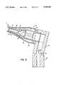
- FIG. 1illustrates a radiation detector for tympanic temperature measurements in accordance with the present invention.
- FIG. 2is a cross-sectional view of the extension of the detector of FIG. 1 in which the thermopile radiation sensor is positioned.
- FIG. 3is a block diagram of the electronic circuit of the detector of FIG. 1.
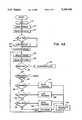
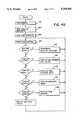
- FIGS. 4A-4Dare flow charts of the system firmware.
- the radiation detector 12 of FIG. 1includes a flat housing 14 with a digital display 16 for displaying a tympanic temperature measurement.
- the displaymay be located anywhere on the housing, it is preferred that it be positioned on the end so the user is not inclined to watch it during a measurement.
- the instrumentmakes an accurate measurement when rotated to scan the ear canal, and the user should concentrate on only the scanning motion. Then the display can be read
- a thermopile radiation sensoris supported within a probe 18 at the opposite end of the housing 14.
- the extension 18extends orthogonally from an intermediate extension 20 which extends at an angle of about 15 degrees from the housing 14.
- the head of the detector including the extension 18 and 20has the appearance of a conventional otoscope.
- An on/off switch 22is positioned on the housing.
- FIG. 2A cross-sectional view of the extension of the detector is illustrated in FIG. 2.
- a base portion 22is positioned within the housing 14, and the housing clamps about a groove 24.
- the portion 20extends at about a 15 degree angle from the housing and thus from the base portion 22.
- the extension 18is tapered toward its distal end at 26 so that it may be comfortably positoned in the ear to view the tympanic membrane and/or ear canal.
- the edge at the end of the probeis rounded so that when the probe is inserted into the ear it can be rotated somewhat without discomfort to the patient.
- the probeis also curved like an otoscope to avoid interference with the ear. By thus rotating the probe, the ear canal is scanned and, at some orientation of the probe during that scan, one can be assured that the maximum temperature is viewed. Since the ear canal cavity leading to the tympanic area is the area of highest temperature, the instrument is set in a peak detection mode, and the peak detected during the scan is taken as the tympanic temperature.
- thermopile 28is positioned within a can 30 of high conductivity material such as copper.
- the conductivityshould be greater than two watts per centimeter per degree Kelvin.
- the canis filled with a gas of low thermal conductivity such as Xenon.
- the thermopile 28is positioned within a rear volume. 31 It is mounted to an assembly which includes a flange 33.
- the volumeis sealed by cold welding of the flange 33 to a flange 41 extending from the can. Cold welding is the preferred approach to making the seal and, to utilize past welding fixtures, the outer diameter of the can is limited.
- the thermopileviews the tympanic membrane area through a radiation guide 32.
- the radiation guide 32is gold plated to minimize oxidation. It is closed at its forward end by a germanium window 35. To minimize expense, the window is square with each side slightly longer than the diameter of the radiation guide 32.
- the windowis cemented with epoxy within a counterbore in a flange 37 at the end of the radiation guide. The epoxy serves as a gas seal and mechanical support for the somewhat brittle germanium window.
- the flangeserves to protect the germanium window should the detector be dropped.
- the diagonal of the windowis less than the diameter of the counterbore, and its thickness is less than the depth of the counterbore. Therefore, if the detector is dropped, any force which presses the plastic housing toward the window is absorbed by the flange.
- the germaniumneed only withstand the forces due to its own inertia.
- thermopile flakewhen directly viewing the tympanic membrane, also views no more than about 1.5 centimeters along the ear canal and preferably less than one centimeter.
- a better view of the tympanic membranealso results from the cylindrical extension 43 beyond the conical portion of the extension 18. With the ear canal straightened by the probe, the extension 43 can extend well into the ear canal beyond any hair at the canal opening.
- the tympanic membraneis about 2.5 centimeters from the opening of the ear canal.
- the conical portion of the extension 18prevents the tip of the extension from extending more than about eight millimeters into the ear canal. Beyond that depth, the patient suffers noticeable discomfort.
- the ear canalwhich is about eight millimeters wide is viewed about eight millimeters from the tip of the extension 18.
- the radiation guideis directed toward the membrane. The result is a more accurate reading of the tympanic temperature which is closer to core temperature.
- the narrow field of viewis obtained by two changes to the prior radiation guide.
- the reflectivity within the guideis reduced. Radiation entering the tube at greater angles must be reflected a greater number of times from the radiation guide before reaching the thermopile flake. With the higher emissivity, such radiation is less likely to reach the flake to be detected.
- the field of viewis further decreased by extending the enlarged rear volume between the flake and the radiation guide. Radiation which enters the radiation guide at greater angles, yet travels through the radiation guide, leaves the guide at greater angles and is thus unlikely to be viewed by the flake.
- the length of the radiation guideis another parameter which affects the field of view. By using a planoconvex lens as the window 35, the field of view can be further limited.
- thermopileBoth of the above approaches to decreasing the field of view increase the amount of heat which is absorbed by the can in which the thermopile is mounted.
- the added heat loadadds to the importance that the can, including the radiation guide, have a large thermal mass and high thermal conductivity as discussed below.
- the volume 31 surrounding the thermopile and the radiation guideare formed of a single piece of high conductivity copper.
- This unitary constructioneliminates any thermal barriers between the foremost end of the radiation guide and the portion of the can surrounding the thermopile which serves as the cold junction of the thermopile.
- at least a portion of added thermal mass which surrounds the radiation guideis unitary with the can as well.
- a taper 39results in an enlarged region 41 which serves as a thermal mass in accordance with the principals of the parent application.
- the taper 39continues along a conductive thermal mass 34 which surrounds the can and a conductive plug 36. Both the mass 34 and plug 36 are of copper and are in close thermal contact with the can 30.
- the outer sleeve 38 of the extension 18 and the intermediate extension 20are of plastic material of low thermal conductivity.
- the sleeve 38is separated from the can 30 and thermal mass 34 by an insulating air space 40.
- the taper of the can 30 and thermal mass 34permits the insulating space to the end of the extension while minimizing the thermal resistance from the end of the tube 32 to the thermopile, a parameter discussed in detail below.
- the inner surface of the plastic sleeve 38may be coated with a good thermal conductor to distribute across the entire sleeve any heat received from contact with the ear. Twenty mils of copper coating would be suitable.
- the portion of the sleeve 38 at the foremost end of extension 18has a region 43 of constant outer diameter before a tapered region 45.
- the region of constant outer diameterreduces the outer diameter at the distal end and minimizes interference when rotating the extension in the ear to view the tympanic membrane area.
- the tapered regionis spaced six millimeters from the end of the extension to allow penetration of the extension into the ear canal by no more than about eight millimeters.
- thermopileOne of the design goals of the device was that it always be in proper calibration without requiring a warm-up time. This precluded the use a heated target in a chopper unit or heating of the cold junction of the thermopile as was suggested in the O'Hara et al. U.S. Pat. No. 4,602,642. To accomplish this design goal, it is necessary that the system be able to operate with the thermopile at any of a wide range of ambient temperatures and that the thermopile output have very low sensitivity to any thermal perturbations.
- thermopileThe output of the thermopile is a function of the difference in temperature between its warm junction, heated by radiation, and its cold junction which is in close thermal contact with the can 30.
- the hot junctionrespond only to radiation viewed through the window 35, it is important that the radiation guide 32 be, throughout a measurement, at the same temperature as the cold junction.
- changes in temperature in the guide 32must be held to a minimum, and any such changes should be distributed rapidly to the cold junction to avoid any thermal gradients.
- the tube 32 and the can 30are, of course, well insulated by means of the volume of air 40. Further, a high conductance thermal path is provided to the cold junction. This conductance is enhanced by the unitary construction.
- the can 30is in close thermal communication with the thermal masses 34 and 36, and the high conductivity and thickness of the thermal masses increase the thermal conductance.
- a high thermal conductivity epoxy, solder or the likejoins the can and thermal masses.
- the solder or epoxyprovides a significant reduction in thermal resistance. Where solder is used, to avoid damage to the thermopile which is rated to temperatures of 125° C. a low temperature solder of indium-tin alloy which flows at 100° C. is allowed to flow into the annular mass 34 to provide good thermal coupling between all elements.
- the thermal resistance from the outer surface of the plastic sleeve 38 to the conductive thermal massis high to minimize thermal perturbations to the inner thermal mass.
- the thermal mass of the can 30, annular mass 34 and plug 36should be large.
- the thermal resistance between any two points of the thermal massshould be low.
- any external thermal disturbancessuch as when the extension contacts skin, only reach the conductive thermal mass at extremely low levels during a measurement period of a few seconds; due to the large thermal mass of the material in contact with the cold junction, any such heat transfer only causes small changes in temperature; and due to the good thermal conductance throughout the thermal mass, any changes in temperature are distributed quickly and are reflected in the cold junction temperature quickly so that they do not affect temperature readings.
- the thermal RC time constant for thermal conduction through the thermal barrier to the thermal mass and tubeshould be at least two orders of magnitude greater than the thermal RC time constant for the temperature response of the cold junction to heat transferred to the tube and thermal mass.
- the RC time constant for conduction through the thermal barrieris made large by the large thermal resistance through the thermal barrier and by the large thermal capacitance of the thermal mass.
- the RC time constant for response of the cold junctionis made low by the low resistance path to the cold junction through the highly conductive copper can and thermal mass, and the low thermal capacitance of the stack of beryllium oxide rings and pin conductors to the thermopile.
- the thermal resistance through the thermal barrier and the internal thermal resistancecan be increased by increased radial dimensions
- the capacitance of the thermal masscan be increased by increasing its size
- the thermal resistance through the longitudinal thermal path through the tubecan be decreased by increasing its size.
- the sizemust be limited to permit the extension to be readily positioned and manipulated within the ear.
- leads to the systemare kept to small diameters. Further, they are embedded in the plug 36 through bores 70; thus, any heat brought into the system through those leads is quickly distributed throughout the thermal mass, and only small changes in temperature and small gradients result.
- thermopile 28Because the temperature of the thermal mass is not controlled, and the response of the thermopile 28 is a function of its cold junction temperature, the cold junction temperature must be monitored. To that end, a thermistor is positioned at the end of a central bore 72 in the plug 36.
- FIG. 3A schematic illustration of the electronics in the housing 14, for providing a temperature readout on display 16 in response to the signal from the thermopile, is presented in FIG. 3.
- the systemis based on a microprocessor 73 which processes software routines included in read only memory within the processor chip
- the processormay be a 6805 processor sold by Motorola.
- the voltage generated across the thermopile 28 due to a temperature differential between the hot and cold junctionsis amplified in an operational amplifier 74.
- the analog output from the amplifier 74is applied as one input to a multiplexer 76.
- Another input to the multiplexer 76is a voltage taken from a voltage divider R1, R2 which is indicative of the potential V+ from the power supply 78.
- a third input to the multiplexer 76is the potential across a thermistor RT1 mounted in the bore 72 of block 36.
- the thermistor RT1is coupled in a voltage divider circuit with R3 across a reference potential VRef.
- the final input to the multiplexeris a potential taken from a potentiometer R4 which may be adjusted by a user.
- the systemmay be programmed to respond to that input in any of a number of ways.
- the potentiometermay be used as a gain control or as a DC offset control.
- one of the four inputsmay be selected by the select lines 78.
- the selected analog signalis applied to a multiple slope analog system 80 used by the microprocessor in an integrating analog-to-digital conversion 80.
- the subsystem 80may be a TSC500A sold by Teledyne. It utilizes the reference voltage VRef from a reference source 82.
- the microprocessor 73responds to the output from the convertor 80 to generate a count indicative of the analog input to the convertor.
- the microprocessordrives four 7-segment LED displays 82 in a multiplexed fashion Individual displays are selected sequentially through a column driver 84, and within each selected display the seven segments are controlled through segment drivers 86.
- the switch 22 on the housingWhen the switch 22 on the housing is pressed, it closes the circuit from the battery 78 through resistors R5 and R6 and diode D1 to ground.
- the capacitor C1is quickly charged and field effect transistor T1 is turned on.
- the regulator 86provides the regulated +5 volts to the system. It also provides a reset signal to the microprocessor. The reset signal is low until the +5 volt reference is available and thus holds the microprocessor in a reset state. When the +5 volts is available, the reset signal goes high, and the microprocessor begins its programmed routine.
- the switch 22When the switch 22 is released, it opens its circuit, but a charge is maintained on capacitor C1 to keep transistor T1 on. Thus, the system continues to operate. However, the capacitor C1 and transistor T1 provide a very simple watchdog circuit. Periodically, the microprocessor applies a signal through driver 84 to the capacitor C1 to recharge the capacitor and thus keep the transistor T1 on. If the microprocessor should fail to continue its programmed routine, it fails to charge the capacitor C1 within a predetermined time during which the charge on C1 leaks to a level at which transistor T1 turns off. Thus, the microprocessor must continue in its programmed routine or the system shuts down. This prevents spurious readings when the processor is not operating properly.
- the switch 22can be used as an input through diode D2 to the microprocessor to initiate any programmed action of the processor.
- the systemhas a sound output 90 which is driven through the driver 84 by the microprocessor.
- a digital-to-analog convertor 92is provided. When selected by line 94, the convertor converts serial data on line 96 to an analog output made available to a user.
- Both calibration and characterization data required for processing by the microprocessormay be stored in an electrically erasable programmable read only memory (EEPROM) 100.
- the EEPROMmay, for example, be a 93c46 sold by International CMOS Technologies. Inc.
- the datamay be stored in the EEPROM by the microprocessor when the EEPROM is selected by line 102. Once stored in the EEPROM. the data is retained even after power down.
- electrically programmableonce programmed the EEPROM serves as a virtually nonvolatile memory.
- the EEPROMmay be programmed through the microprocessor to store calibration data for calibrating the thermistor and thermopile. Further, characterization data which defines the personality of the infrared detector may be stored. For example, the same electronics hardware, including the microprocessor 73 and its internal program, may be used for a tympanic temperature detector in which the output is accurate in the target temperature range of about 60° F. to a 110° F. or it may be used as an industrial detector in which the target temperature range would be from about 0° F. to 100° F. Further, different modes of operation may be programmed into the system. For example, several different uses of the sound source 90 are available.
- the EEPROMis readily programmed by means of an optical communication link which includes a transistor T2 associated with the display.
- a communication bootmay be placed over the end of the detector during a calibration/characterization procedure.
- a photodiode in the bootgenerates a digitally encoded optical signal which is filtered and applied to the detector T2 to provide an input to the microprocessor 73.
- the microprocessormay communicate optically to a detector in the boot by flashing specific segments of the digital display 82. Through that communication link, an outside computer 106 can monitor the outputs from the thermistor and thermopile and perform a calibration of the devices.
- a unit to be calibratedis pointed at each of two black body radiation sources while the microprocessor 73 converts the signals and sends the values to the external computer.
- the computeris provided with the actual black body temperatures and ambient temperature in the controlled environment of the detector, computes calibration variables and returns those variable to be stored in the detector EEPROM. Similarly, data which characterizes a particular radiation detector may be communicated to the microprocessor for storage in the EEPROM.
- a switch 108is positioned behind a hole 110 (FIG. 1) in the radiation detector so that it may be actuated by a rigid metal wire or pin. Through that switch, the user may control some specific mode of operation such as converting the detector from degrees Fahrenheit to degrees centigrade. That mode of operation may be stored by the microprocessor 73 in the EEPROM so that the detector continues to operate in a specific mode until a change is indicated by closing the switch 108.
- a switch 106may be provided either internally or through the housing to the user to set a mode of operation of the detector. By positioning the switch at either the lock position, the scan position or a neutral position, any of three modes may be selected.
- the first modeis the normal scan mode where the display is updated continuously.
- a second modeis a lock mode where the display locks after a selectable delay and then remains frozen until power is cycled or, optionally, the power-on button is pushed.
- the sound sourcemay be caused to sound at the time of lock.
- the third modeis the peak mode where the display reads the maximum value found since power-on until power is cycled or, optionally, the power-on button is pushed.
- the processordetermines when the voltage from the divider R1, R2 drops below each of two thresholds. Below the higher threshold, the processor periodically enables the sound source to indicate that the battery is low and should be replaced but allows continued readout from the display. Below the lower threshold, the processor determines that any output would be unreliable and no longer displays temperature readings. The unit would then shut down upon release of the power button.
- the target temperatureis computed from the relationship
- T Tis the target temperature
- Khis a gain calibration factor
- T His the hot junction temperature.
- the gain calibration factor Khis temperature compensated by the relationship, ##EQU1## where G is an empirically determined gain in the system. Tco is the temperature coefficient of the Seebeck coefficient of the thermopile and Tz is the temperature at which the instrument was calibrated. The use of the average temperature of the thermopile rather than the cold junction temperature provides for a much more accurate response where a target temperature is significantly different from the ambient temperature.
- the relationship by which the target temperature is determinedincludes the hot junction temperature as the second term rather than the cold junction temperature.
- Hot junction temperatureis computed from the relationship
- thermopilethe number of junctions in the thermopile and ⁇ tav is the Seebeck coefficient at the average temperature of the thermopile.
- the Seebeck coefficientcan be determined from the relationship ##EQU2## where ⁇ ts is the specified Seebeck coefficient at a particular specification temperature and T S is that specification temperature. Again, it can be seen that temperature compensation is based on the average thermopile temperature rather than just the cold junction temperature.
- V Scan be determined from the digital value available to the processor from the equation: ##EQU3## where K AD is the analog-to-digital conversion factor in volts/bit and G FE is the gain of the front end amplifier.
- the microprocessormakes the following computations: First the signal from thermistor RT1 is converted to temperature using a linear approximation. Temperature is defined by a set of linear equations
- xis an input and xo is an input end point of a straight line approximation.
- the values of M, xo and bare stored in the EEPROM after calibration.
- the microprocessordetermines from the values of xo the line segment in which the temperature falls and then performs the computation for y based on the variables M and b stored in the EEPROM.
- the hot junction temperatureis computed A fourth power representation of the hot junction temperature is then obtained by a lookup table in the processor ROM.
- the sensed radiationmay be corrected using the gain calibration factor Kh, the sensor gain temperature coefficient Tco, the average of the hot and cold junction temperatures and a calibration temperature Tz stored in the EEPROM.
- the corrected radiation signal and the fourth power of the hot junction temperatureare summed, and the fourth root is taken.
- the fourth root calculationis also based on a linear approximation which is selected according to the temperature range of interest for a particular unit. Again, the break points and coefficients for each linear approximation are stored in the EEPROM and are selected as required.
- An additional factor based on ambient temperaturemay also be included as an adjustment.
- the temperature of the ear T e which is sensed by the thermopileis not actually the core temperature T cr .
- T cr and T eThere is thermal resistance between T cr and T e .
- T ewhich is a function of the core temperature of interest and the ambient temperature.
- K Cwhich is a measure of the thermal resistances between T cr , T e and T a
- core temperaturecan be computed as ##EQU4## This computation can account for a difference of from one-half to one degree between core temperature and sensed ear temperature, depending on ambient temperature.
- differential cutaneous temperature scanningthe significance of a given differential reading may be ambient temperature dependent.
- His the digital value of radiation signal presented to the processor
- H ois the electronic offset
- Hcis corrected H (deg K 4 )
- Tcambient and cold junction temperature (deg F)
- Tafis 4th power of Tamb (deg K 4 )
- Ttis target temperature (deg F)
- Tzis ambient temp during cal (deg F)
- Tdis the displayed temperature
- Rtis the thermistor signal
- Khis a radiation sensor gain cal factor
- Ztis a thermistor zero cal factor
- This the hot junction temperature
- ⁇ tsis the Seebeck coefficient of the thermopile at a specified temperature
- Jis the number of junctions in the thermopile
- Tcois a temperature coefficient for the Seebeck coefficient
- Tsis the temperature at which ⁇ ts is specified
- Tcris core temperature
- kcis a constant for computing core temperature
- V Sis the sensor output voltage
- G FEis the gain of the front end amplifier
- K ADis the analog-to-digital conversion factor
- V S(H-H o ) K AD/GFE
- Tc(deg F)Thermistor lookup table (Rt)-Zt
- T H[(Tco*T S +1) ⁇ [(Tco*Ts+1) 2 -(2*Tco)* [(Tco((Tc*Ts)-(Tc 2 /2))+Tc+(V S /J* ⁇ ts )]] 1/2 ]/Tco
- Hc(deg K 4 )Kh*(H-H o )*(1+Tco*((Th-Tc)/2-Tz))
- Thf(deg K 4 )4th power lookup table (Tc)
- FIGS. 4A-4Dprovide a flowchart of the firmware stored in the microprocessor 73. From reset when the instrument is turned on, the system is initialized at 110 and the contents of the EEPROM are read into memory in the microprocessor at 112. At 114 the processor reads the state of power and mode switches in the system. At 116, the system determines whether a mode switch 113 has placed the system in a self-test mode. If not all eights are displayed on the four-digit display 82 for a brief time At 120 the system performs all A-to-D conversions to obtain digital representations of the thermopile output and the potentiometer settings through multiplexor 76.
- the systemthen enters a loop in which outputs dictated by the mode switch are maintained. First the timers are updated at 122 and the switches are again read at 124. When the power is switched off, from 126 the system enters a power down loop at 128 until the system is fully down. At 130, the mode switch is checked and if changed the system is reset. Although not in the tympanic temperature detector, some detectors have a mode switch available to the user so that the mode of operation can be changed within a loop.
- the systemdetermines its mode of operation and enters the appropriate scan process 134, lock process 138 or peak process 142.
- a scan processthe system updates the output to the current reading in each loop.
- a lock processthe system updates the output but locks onto an output after some period of time.
- the peak processthe system output is the highest indication noted during a scan.
- the systemmay respond to the programming from the EEPROM to perform any number of functions as discussed above.
- the peak processwhich is selected for the tympanic temperature measurement, the system locks onto a peak measurement after a preset period of time.
- the systemmay be set at a test mode 144 which will be described with respect to FIG. 4D.
- the raw sensor datais obtained from memory.
- the sensor offset taken from the EEPROMis subtracted at 150 and the ambient temperature previously obtained from the potentiometer RT1 is accessed at 152.
- the temperature coefficient adjustmentis calculated at 154.
- the sensed signalis multiplied by the gain from EEPROM and by the temperature coefficient.
- the fourth power of the ambient temperatureis obtained, and at 160 it is added to the sensor signal.
- the fourth root of the sumis obtained through a lookup table. Whether the display is in degrees centigrade or degrees Fahrenheit is determined at 164. If in degrees centrigrade, a conversion is performed at 166.
- adjustment valuesincluding that from the potentiometer R4, are added.
- Analog-to-Digital conversionis performed periodically during an interrupt to the loop of FIG. 4A which occurs every two milliseconds.
- the interrupt routineis illustrated in FIG. 4C.
- Timer countersare updated at 170.
- A-to-D conversionsare made from 172 only every 100 milliseconds when a flag has been set in the prior interrupt cycle. During most interrupts, an A/D conversion does not occur.
- the 100-millisecond counteris checked at 174, and if the count has expired, a flag is set at 176 for the next interrupt. The flag is checked at 178 and, if found, the display is updated at 180. The system then returns to the main loop of FIG. 4A.
- thermopile sensor conversionis performed nine out of ten cycles through the conversion loop.
- the systemchecks to determine whether a conversion is made from the potentiometer R4 or from the battery voltage divider R1, R2 at 192. These conversions are made alternately.
- FIG. 4Dillustrates the self-test sequence which is called by the mode switch 113 only during assembly.
- the beeper sounds at 182 and all display segmentsare displayed at 184.
- the systemsteps each character of the display from zero through nine at 186.
- the systemthen enters a test loop.
- the systemsenses whether the button 108 has been pressed. If so, a display counter is incremented at 190.
- the display for the unitthen depends on the count of the display counter. With the zero count, the adjustment potentiometer value is displayed at 192.
- the display counteris incremented by pressing the button 108, the raw sensor data is displayed. With the next increment, ambient temperature is displayed at 196, and with the next increment, the raw output from the ambient temperature sensor RT1 is displayed. With the next increment, the battery voltage is displayed.
- the assemblersets the mode switch to the proper operating mode.
Landscapes
- Physics & Mathematics (AREA)
- General Physics & Mathematics (AREA)
- Spectroscopy & Molecular Physics (AREA)
- Measuring And Recording Apparatus For Diagnosis (AREA)
- Radiation Pyrometers (AREA)
Abstract
Description
T.sub.T.sup.4 =Kh(H-H.sub.o)+T.sub.H.sup.4 (1)
V.sub.s =J α.sub.tav (T.sub.H -T.sub.C) (3)
T.sub.H =[(Tco*T.sub.S +1)±[(Tco*Ts+1).sup.2 -(2*Tco)8 [(Tco((Tc*Ts)-(Tc.sup.2 /2))+Tc+(V.sub.S /J*α.sub.ts)] .sup.1/2 ]/Tco(5)
y=M(x-xo)+b
Claims (5)
Priority Applications (9)
| Application Number | Priority Date | Filing Date | Title |
|---|---|---|---|
| US07/646,855US5199436A (en) | 1988-12-06 | 1991-01-28 | Radiation detector having improved accuracy |
| US07/760,006US5445158A (en) | 1988-12-06 | 1991-09-13 | Radiation detector probe |
| US07/832,109US5325863A (en) | 1988-12-06 | 1992-02-06 | Radiation detector with high thermal stability |
| US08/333,205US5653238A (en) | 1988-12-06 | 1994-11-02 | Radiation detector probe |
| US08/682,260US6047205A (en) | 1988-12-06 | 1996-07-17 | Radiation detector probe |
| US09/293,477US6219573B1 (en) | 1989-04-14 | 1999-04-16 | Radiation detector probe |
| US09/808,619US20010027274A1 (en) | 1988-12-06 | 2001-03-14 | Radiation detector probe |
| US10/667,135US20040122338A1 (en) | 1988-12-06 | 2003-09-19 | Radiation detector probe |
| US11/169,272US20060062274A1 (en) | 1988-12-06 | 2005-06-28 | Radiation detector probe |
Applications Claiming Priority (3)
| Application Number | Priority Date | Filing Date | Title |
|---|---|---|---|
| US07/280,546US4993419A (en) | 1988-12-06 | 1988-12-06 | Radiation detector suitable for tympanic temperature measurement |
| US07/338,968US5012813A (en) | 1988-12-06 | 1989-04-14 | Radiation detector having improved accuracy |
| US07/646,855US5199436A (en) | 1988-12-06 | 1991-01-28 | Radiation detector having improved accuracy |
Related Parent Applications (1)
| Application Number | Title | Priority Date | Filing Date |
|---|---|---|---|
| US07/338,968DivisionUS5012813A (en) | 1988-12-06 | 1989-04-14 | Radiation detector having improved accuracy |
Related Child Applications (2)
| Application Number | Title | Priority Date | Filing Date |
|---|---|---|---|
| US07/760,006Continuation-In-PartUS5445158A (en) | 1988-12-06 | 1991-09-13 | Radiation detector probe |
| US07/760,006ContinuationUS5445158A (en) | 1988-12-06 | 1991-09-13 | Radiation detector probe |
Publications (1)
| Publication Number | Publication Date |
|---|---|
| US5199436Atrue US5199436A (en) | 1993-04-06 |
Family
ID=27403156
Family Applications (1)
| Application Number | Title | Priority Date | Filing Date |
|---|---|---|---|
| US07/646,855Expired - LifetimeUS5199436A (en) | 1988-12-06 | 1991-01-28 | Radiation detector having improved accuracy |
Country Status (1)
| Country | Link |
|---|---|
| US (1) | US5199436A (en) |
Cited By (47)
| Publication number | Priority date | Publication date | Assignee | Title |
|---|---|---|---|---|
| US5653238A (en)* | 1988-12-06 | 1997-08-05 | Exergen Corporation | Radiation detector probe |
| US5725308A (en)* | 1994-12-23 | 1998-03-10 | Rtd Technology, Inc. | Quick registering thermometer |
| US5740809A (en)* | 1994-10-26 | 1998-04-21 | Baratta; Francis I. | Noninvasive infrared blood flow detector |
| AU696919B2 (en)* | 1995-06-23 | 1998-09-24 | Thermoscan, Inc. | Durable tympanic probe and thermometer |
| US5813982A (en)* | 1994-02-22 | 1998-09-29 | Baratta; Francis I. | Noncontacting portable infrared intra-ocular pressure sensor |
| US5833367A (en) | 1996-11-12 | 1998-11-10 | Trutek, Inc. | Tympanic thermometer probe cover |
| US5919143A (en)* | 1998-01-12 | 1999-07-06 | Mdi Instruments, Inc. | Apparatus and method for analysis of acoustic reflectance and thermal radiation of an ear |
| WO1999034729A1 (en) | 1998-01-12 | 1999-07-15 | Mdi Instruments, Inc. | Ear examining device with temperature sensor |
| US5967992A (en) | 1998-06-03 | 1999-10-19 | Trutex, Inc. | Radiometric temperature measurement based on empirical measurements and linear functions |
| US6001066A (en) | 1997-06-03 | 1999-12-14 | Trutek, Inc. | Tympanic thermometer with modular sensing probe |
| US6030117A (en) | 1996-11-12 | 2000-02-29 | Trutek, Inc. | Tympanic thermometer probe cover |
| WO2000016051A1 (en) | 1998-09-11 | 2000-03-23 | Exergen Corporation | Temporal artery temperature detector |
| WO2000024312A1 (en) | 1998-10-23 | 2000-05-04 | Becton, Dickinson And Company | Sensing ear temperature, acoustic reflectance and chemical components in the ear |
| US6090050A (en)* | 1998-07-16 | 2000-07-18 | Salix Medical, Inc. | Thermometric apparatus and method |
| US6123454A (en) | 1999-06-11 | 2000-09-26 | Trutek, Inc. | Tympanic thermometer disposable probe cover with further stretching prevention structure |
| US6219573B1 (en) | 1989-04-14 | 2001-04-17 | Exergen Corporation | Radiation detector probe |
| US20020098593A1 (en)* | 2000-11-17 | 2002-07-25 | Flir Systems Boston, Inc. | Apparatus and methods for infrared calorimetric measurements |
| US6435711B1 (en) | 1998-09-15 | 2002-08-20 | Jonathan Gerlitz | Infrared ear thermometer |
| US20020146345A1 (en)* | 2000-11-17 | 2002-10-10 | Neilson Andy C. | Apparatus and methods for infrared calorimetric measurements |
| US6522912B1 (en)* | 1998-05-06 | 2003-02-18 | Matsushita Electric Industrial Co., Ltd. | Ear type thermometer |
| US6641301B2 (en) | 2001-04-09 | 2003-11-04 | Exergen Corporation | Radiation detector with passive air purge and reduced noise |
| US20040110301A1 (en)* | 2000-11-17 | 2004-06-10 | Neilson Andy C | Apparatus and methods for measuring reaction byproducts |
| US20040165646A1 (en)* | 2003-02-20 | 2004-08-26 | Shidemantle Jack P. | Digitally modified resistive output for a temperature sensor |
| US20040240516A1 (en)* | 2002-12-12 | 2004-12-02 | James Harr | Thermal tympanic thermometer tip |
| US20040254497A1 (en)* | 2000-09-15 | 2004-12-16 | Jacob Fraden | Ear temperature monitor and method of temperature measurement |
| US20050043631A1 (en)* | 2003-08-19 | 2005-02-24 | Jacob Fraden | Medical body core thermometer |
| US20050094705A1 (en)* | 2003-11-05 | 2005-05-05 | Microlife Intellectual Property Gmbh | Infrared thermometer and method for determining temperature |
| US20060222048A1 (en)* | 1997-06-24 | 2006-10-05 | Francesco Pompei | Ambient and perfusion normalized temperature detector |
| US20060239332A1 (en)* | 2002-12-12 | 2006-10-26 | Sherwood Services Ag | Thermal tympanic thermometer |
| US20070116314A1 (en)* | 2005-10-11 | 2007-05-24 | Morning Pride Manufacturing, L.L.C. | Facemask-earpiece combination |
| US20090204008A1 (en)* | 2008-02-08 | 2009-08-13 | Daniel Beilin | Whole body infrared thermography systems and methods |
| US20100087726A1 (en)* | 2008-10-02 | 2010-04-08 | Jan Ruff | Magnetic resonance method and apparatus for determining a kidney function parameter |
| US7785266B2 (en) | 2003-08-19 | 2010-08-31 | Advanced Monitors Corporation | Medical thermometer for determining body core temperature |
| US20100268114A1 (en)* | 2009-04-15 | 2010-10-21 | Arizant Healthcare Inc. | Deep tissue temperature probe constructions |
| US20100268113A1 (en)* | 2009-04-15 | 2010-10-21 | Arizant Healthcare Inc. | Deep tissue temperature probe constructions |
| US20110051776A1 (en)* | 2009-08-31 | 2011-03-03 | Arizant Healthcare Inc. | Flexible deep tissue temperature measurement devices |
| US20110194585A1 (en)* | 2010-02-09 | 2011-08-11 | Abhishek Shrivastava | Multiple object non-contact thermometer |
| US20110228810A1 (en)* | 2010-02-09 | 2011-09-22 | O'hara Gary | Multiple object talking non-contact thermometer |
| US8128280B2 (en) | 2005-04-29 | 2012-03-06 | Tecnimed S.R.L. | Temperature measuring device particularly of a patient |
| EP2437039A2 (en) | 2010-09-30 | 2012-04-04 | Medisim Ltd. | Ergonomic hand held thermometer |
| US20120257649A1 (en)* | 2007-06-12 | 2012-10-11 | Bio Echo Net Inc | Ear thermometer and measuring apparatus used with it |
| US8292495B2 (en) | 2010-04-07 | 2012-10-23 | Arizant Healthcare Inc. | Zero-heat-flux, deep tissue temperature measurement devices with thermal sensor calibration |
| US8292502B2 (en) | 2010-04-07 | 2012-10-23 | Arizant Healthcare Inc. | Constructions for zero-heat-flux, deep tissue temperature measurement devices |
| CN104155008A (en)* | 2014-07-28 | 2014-11-19 | 上海电力学院 | Method for correcting measuring errors of infrared temperature monitoring system |
| US9354122B2 (en) | 2011-05-10 | 2016-05-31 | 3M Innovative Properties Company | Zero-heat-flux, deep tissue temperature measurement system |
| US9872812B2 (en) | 2012-09-28 | 2018-01-23 | Kpr U.S., Llc | Residual pressure control in a compression device |
| US11022496B2 (en) | 2018-06-29 | 2021-06-01 | Tecnimed S.R.L. | Infrared thermometer |
Citations (30)
| Publication number | Priority date | Publication date | Assignee | Title |
|---|---|---|---|---|
| US2658390A (en)* | 1948-02-06 | 1953-11-10 | Leeds & Northrup Co | Radiation pyrometry |
| US3273395A (en)* | 1963-08-05 | 1966-09-20 | Barnes Eng Co | Automatic ambient temperature compensation for a medical thermometer |
| US3282106A (en)* | 1963-01-28 | 1966-11-01 | Barnes Eng Co | Method of measuring body temperature |
| US3491596A (en)* | 1967-10-02 | 1970-01-27 | Vito Charles P De | Temperature sensing device |
| DE1914468A1 (en)* | 1969-03-21 | 1970-11-12 | Siemens Ag | Method and device for non-contact temperature measurement |
| GB1226540A (en)* | 1967-12-12 | 1971-03-31 | ||
| US3581570A (en)* | 1967-09-05 | 1971-06-01 | Garrett Corp | Thermal radiation sensor |
| US3777568A (en)* | 1971-12-21 | 1973-12-11 | Sensors Inc | D. c. electronic apparatus for ir radiation temperature measurement |
| US3878836A (en)* | 1973-08-23 | 1975-04-22 | Products Int Marketing | Disposable speculum for tympanic thermometer |
| US3933045A (en)* | 1970-05-01 | 1976-01-20 | National Research Development Corporation | Temperature measurement |
| GB1425765A (en)* | 1972-05-06 | 1976-02-18 | Schiller A | Replaceable cap for the sensing probe of an electronic device for measuring body temperature and a method of producing such a cap |
| US3949740A (en)* | 1973-08-23 | 1976-04-13 | Products International Marketing | Disposable speculum for tympanic thermometer |
| US4005605A (en)* | 1974-07-22 | 1977-02-01 | Mikron Instrument Company, Inc. | Remote reading infrared thermometer |
| US4062239A (en)* | 1974-07-15 | 1977-12-13 | Fowler Charles F | Method and apparatus for temperature probe cover with provision for sanitary disposal |
| US4456390A (en)* | 1981-10-26 | 1984-06-26 | Wahl Instruments, Inc. | Noncontact temperature measuring device |
| US4566808A (en)* | 1983-02-16 | 1986-01-28 | Exergen Corporation | Scanning radiation detector |
| US4602642A (en)* | 1984-10-23 | 1986-07-29 | Intelligent Medical Systems, Inc. | Method and apparatus for measuring internal body temperature utilizing infrared emissions |
| US4614442A (en)* | 1985-01-18 | 1986-09-30 | Poncy George W | Thermometer sheath package for electronic thermometers |
| EP0201790A2 (en)* | 1985-05-08 | 1986-11-20 | Intelligent Medical Systems, Inc. | Disposable Speculum |
| US4626686A (en)* | 1984-04-09 | 1986-12-02 | Exergen Corporation | Variable field of view heat scanner |
| US4634294A (en)* | 1979-09-12 | 1987-01-06 | Raytek, Inc. | Hand-held digital temperature measuring instrument |
| US4636091A (en)* | 1985-06-27 | 1987-01-13 | Exergen Corporation | Radiation detector having temperature readout |
| US4684018A (en)* | 1983-04-15 | 1987-08-04 | Devello Ab | Thermometer sheath |
| US4722612A (en)* | 1985-09-04 | 1988-02-02 | Wahl Instruments, Inc. | Infrared thermometers for minimizing errors associated with ambient temperature transients |
| US4784149A (en)* | 1986-01-13 | 1988-11-15 | Optical Sensors, Inc. | Infrared thermometer with automatic calibration |
| US4790324A (en)* | 1984-10-23 | 1988-12-13 | Intelligent Medical Systems, Inc. | Method and apparatus for measuring internal body temperature utilizing infrared emissions |
| US4797840A (en)* | 1985-04-17 | 1989-01-10 | Thermoscan Inc. | Infrared electronic thermometer and method for measuring temperature |
| US4831258A (en)* | 1988-03-04 | 1989-05-16 | Exergen Corporation | Dual sensor radiation detector |
| US4895164A (en)* | 1988-09-15 | 1990-01-23 | Telatemp Corp. | Infrared clinical thermometer |
| US5018872A (en)* | 1988-11-01 | 1991-05-28 | Diatek, Inc. | Probe assembly for infrared thermometer |
- 1991
- 1991-01-28USUS07/646,855patent/US5199436A/ennot_activeExpired - Lifetime
Patent Citations (31)
| Publication number | Priority date | Publication date | Assignee | Title |
|---|---|---|---|---|
| US2658390A (en)* | 1948-02-06 | 1953-11-10 | Leeds & Northrup Co | Radiation pyrometry |
| US3282106A (en)* | 1963-01-28 | 1966-11-01 | Barnes Eng Co | Method of measuring body temperature |
| US3273395A (en)* | 1963-08-05 | 1966-09-20 | Barnes Eng Co | Automatic ambient temperature compensation for a medical thermometer |
| US3581570A (en)* | 1967-09-05 | 1971-06-01 | Garrett Corp | Thermal radiation sensor |
| US3491596A (en)* | 1967-10-02 | 1970-01-27 | Vito Charles P De | Temperature sensing device |
| GB1226540A (en)* | 1967-12-12 | 1971-03-31 | ||
| DE1914468A1 (en)* | 1969-03-21 | 1970-11-12 | Siemens Ag | Method and device for non-contact temperature measurement |
| US3933045A (en)* | 1970-05-01 | 1976-01-20 | National Research Development Corporation | Temperature measurement |
| US3777568A (en)* | 1971-12-21 | 1973-12-11 | Sensors Inc | D. c. electronic apparatus for ir radiation temperature measurement |
| GB1425765A (en)* | 1972-05-06 | 1976-02-18 | Schiller A | Replaceable cap for the sensing probe of an electronic device for measuring body temperature and a method of producing such a cap |
| US3878836A (en)* | 1973-08-23 | 1975-04-22 | Products Int Marketing | Disposable speculum for tympanic thermometer |
| US3949740A (en)* | 1973-08-23 | 1976-04-13 | Products International Marketing | Disposable speculum for tympanic thermometer |
| US4062239A (en)* | 1974-07-15 | 1977-12-13 | Fowler Charles F | Method and apparatus for temperature probe cover with provision for sanitary disposal |
| US4005605A (en)* | 1974-07-22 | 1977-02-01 | Mikron Instrument Company, Inc. | Remote reading infrared thermometer |
| US4634294A (en)* | 1979-09-12 | 1987-01-06 | Raytek, Inc. | Hand-held digital temperature measuring instrument |
| US4456390A (en)* | 1981-10-26 | 1984-06-26 | Wahl Instruments, Inc. | Noncontact temperature measuring device |
| US4566808A (en)* | 1983-02-16 | 1986-01-28 | Exergen Corporation | Scanning radiation detector |
| US4684018A (en)* | 1983-04-15 | 1987-08-04 | Devello Ab | Thermometer sheath |
| US4626686A (en)* | 1984-04-09 | 1986-12-02 | Exergen Corporation | Variable field of view heat scanner |
| US4662360A (en)* | 1984-10-23 | 1987-05-05 | Intelligent Medical Systems, Inc. | Disposable speculum |
| US4602642A (en)* | 1984-10-23 | 1986-07-29 | Intelligent Medical Systems, Inc. | Method and apparatus for measuring internal body temperature utilizing infrared emissions |
| US4790324A (en)* | 1984-10-23 | 1988-12-13 | Intelligent Medical Systems, Inc. | Method and apparatus for measuring internal body temperature utilizing infrared emissions |
| US4614442A (en)* | 1985-01-18 | 1986-09-30 | Poncy George W | Thermometer sheath package for electronic thermometers |
| US4797840A (en)* | 1985-04-17 | 1989-01-10 | Thermoscan Inc. | Infrared electronic thermometer and method for measuring temperature |
| EP0201790A2 (en)* | 1985-05-08 | 1986-11-20 | Intelligent Medical Systems, Inc. | Disposable Speculum |
| US4636091A (en)* | 1985-06-27 | 1987-01-13 | Exergen Corporation | Radiation detector having temperature readout |
| US4722612A (en)* | 1985-09-04 | 1988-02-02 | Wahl Instruments, Inc. | Infrared thermometers for minimizing errors associated with ambient temperature transients |
| US4784149A (en)* | 1986-01-13 | 1988-11-15 | Optical Sensors, Inc. | Infrared thermometer with automatic calibration |
| US4831258A (en)* | 1988-03-04 | 1989-05-16 | Exergen Corporation | Dual sensor radiation detector |
| US4895164A (en)* | 1988-09-15 | 1990-01-23 | Telatemp Corp. | Infrared clinical thermometer |
| US5018872A (en)* | 1988-11-01 | 1991-05-28 | Diatek, Inc. | Probe assembly for infrared thermometer |
Non-Patent Citations (8)
| Title |
|---|
| Det Tronics advertisement, InTech, Oct. 1987, p. 48.* |
| Dexter Research Center product description for the Model 1M Thermopile Detector, Oct. 1980.* |
| Fraden, Jacob, "Application of Piezo/Pyroelectric Films in Medical Transducer" Journal of Clinical Engineering, Mar./Apr. 1988, pp. 133-138. |
| Fraden, Jacob, Application of Piezo/Pyroelectric Films in Medical Transducer Journal of Clinical Engineering, Mar./Apr. 1988, pp. 133 138.* |
| Houdas et al., Human Body Temperature (Plenum Press: NY), 83.* |
| Looney, Joseph M. Jr. and Pompei, Francisco, Ear Thermometry, Reprinted from Medical Electronics, Jun. 1989.* |
| Proceedings of the Eighth Annual Conference of the IEEE/ Engineering in Medicine and Biology Society, Nov. 7 10, 1986, vol. 3 of 3, pp. 1606 1608.* |
| Proceedings of the Eighth Annual Conference of the IEEE/ Engineering in Medicine and Biology Society, Nov. 7-10, 1986, vol. 3 of 3, pp. 1606-1608. |
Cited By (88)
| Publication number | Priority date | Publication date | Assignee | Title |
|---|---|---|---|---|
| US20060062274A1 (en)* | 1988-12-06 | 2006-03-23 | Exergen Corporation | Radiation detector probe |
| US6047205A (en)* | 1988-12-06 | 2000-04-04 | Exergen Corporation | Radiation detector probe |
| US5653238A (en)* | 1988-12-06 | 1997-08-05 | Exergen Corporation | Radiation detector probe |
| US20040122338A1 (en)* | 1988-12-06 | 2004-06-24 | Exergen Corporation | Radiation detector probe |
| US6219573B1 (en) | 1989-04-14 | 2001-04-17 | Exergen Corporation | Radiation detector probe |
| US5813982A (en)* | 1994-02-22 | 1998-09-29 | Baratta; Francis I. | Noncontacting portable infrared intra-ocular pressure sensor |
| US5740809A (en)* | 1994-10-26 | 1998-04-21 | Baratta; Francis I. | Noninvasive infrared blood flow detector |
| US5725308A (en)* | 1994-12-23 | 1998-03-10 | Rtd Technology, Inc. | Quick registering thermometer |
| US6059452A (en)* | 1994-12-23 | 2000-05-09 | Rtd Technology, Inc. | Quick registering thermometer |
| AU696919B2 (en)* | 1995-06-23 | 1998-09-24 | Thermoscan, Inc. | Durable tympanic probe and thermometer |
| US5833367A (en) | 1996-11-12 | 1998-11-10 | Trutek, Inc. | Tympanic thermometer probe cover |
| US6030117A (en) | 1996-11-12 | 2000-02-29 | Trutek, Inc. | Tympanic thermometer probe cover |
| US6042266A (en) | 1996-11-12 | 2000-03-28 | Trutek, Inc. | Tympanic thermometer probe cover |
| US6186959B1 (en) | 1997-06-03 | 2001-02-13 | Trutek, Inc. | Tympanic thermometer with modular sensing probe |
| US6001066A (en) | 1997-06-03 | 1999-12-14 | Trutek, Inc. | Tympanic thermometer with modular sensing probe |
| US20060222048A1 (en)* | 1997-06-24 | 2006-10-05 | Francesco Pompei | Ambient and perfusion normalized temperature detector |
| US7314309B2 (en) | 1997-06-24 | 2008-01-01 | Exergen Corporation | Ambient and perfusion normalized temperature detector |
| US5919143A (en)* | 1998-01-12 | 1999-07-06 | Mdi Instruments, Inc. | Apparatus and method for analysis of acoustic reflectance and thermal radiation of an ear |
| WO1999034729A1 (en) | 1998-01-12 | 1999-07-15 | Mdi Instruments, Inc. | Ear examining device with temperature sensor |
| US6522912B1 (en)* | 1998-05-06 | 2003-02-18 | Matsushita Electric Industrial Co., Ltd. | Ear type thermometer |
| US5967992A (en) | 1998-06-03 | 1999-10-19 | Trutex, Inc. | Radiometric temperature measurement based on empirical measurements and linear functions |
| US6090050A (en)* | 1998-07-16 | 2000-07-18 | Salix Medical, Inc. | Thermometric apparatus and method |
| US6292685B1 (en) | 1998-09-11 | 2001-09-18 | Exergen Corporation | Temporal artery temperature detector |
| US20040152991A1 (en)* | 1998-09-11 | 2004-08-05 | Exergen Corporation | Temporal artery temperature detector |
| EP2317292A2 (en) | 1998-09-11 | 2011-05-04 | Exergen Corporation | Temporal artery temperature detector |
| WO2000016051A1 (en) | 1998-09-11 | 2000-03-23 | Exergen Corporation | Temporal artery temperature detector |
| US7346386B2 (en) | 1998-09-11 | 2008-03-18 | Exergen Corporation | Temporal artery temperature detector |
| US20110092822A1 (en)* | 1998-09-11 | 2011-04-21 | Francesco Pompei | Temporal Artery Temperature Detector |
| US7787938B2 (en) | 1998-09-11 | 2010-08-31 | Exergen Corporation | Temporal artery temperature detector |
| US20080200830A1 (en)* | 1998-09-11 | 2008-08-21 | Exergen Corporation | Temporal artery temperature detector |
| US9194749B2 (en) | 1998-09-11 | 2015-11-24 | Exergen Corporation | Temporal artery temperature detector |
| US6435711B1 (en) | 1998-09-15 | 2002-08-20 | Jonathan Gerlitz | Infrared ear thermometer |
| US6811306B2 (en) | 1998-09-15 | 2004-11-02 | Jonathan Gerlitz | Infrared ear thermometer |
| US6991368B2 (en) | 1998-09-15 | 2006-01-31 | Jonathan Gerlitz | Infrared thermometer |
| US20030016728A1 (en)* | 1998-09-15 | 2003-01-23 | Jonathan Gerlitz | Infrared thermometer |
| WO2000024312A1 (en) | 1998-10-23 | 2000-05-04 | Becton, Dickinson And Company | Sensing ear temperature, acoustic reflectance and chemical components in the ear |
| US6123454A (en) | 1999-06-11 | 2000-09-26 | Trutek, Inc. | Tympanic thermometer disposable probe cover with further stretching prevention structure |
| US7306565B2 (en) | 2000-09-15 | 2007-12-11 | Advanced Monitors Corporation | Ear temperature monitor and method of temperature measurement |
| US20040254497A1 (en)* | 2000-09-15 | 2004-12-16 | Jacob Fraden | Ear temperature monitor and method of temperature measurement |
| US20020098593A1 (en)* | 2000-11-17 | 2002-07-25 | Flir Systems Boston, Inc. | Apparatus and methods for infrared calorimetric measurements |
| US20020146345A1 (en)* | 2000-11-17 | 2002-10-10 | Neilson Andy C. | Apparatus and methods for infrared calorimetric measurements |
| US6991765B2 (en) | 2000-11-17 | 2006-01-31 | Flir Systems Boston, Inc. | Apparatus and methods for infrared calorimetric measurements |
| US20020146836A1 (en)* | 2000-11-17 | 2002-10-10 | Flir Systems Boston, Inc. | Apparatus and methods for infrared calorimetric measurements |
| US20040110301A1 (en)* | 2000-11-17 | 2004-06-10 | Neilson Andy C | Apparatus and methods for measuring reaction byproducts |
| US6835574B2 (en) | 2000-11-17 | 2004-12-28 | Flir Systems Boston, Inc. | Apparatus and methods for infrared calorimetric measurements |
| US6821787B2 (en) | 2000-11-17 | 2004-11-23 | Thermogenic Imaging, Inc. | Apparatus and methods for infrared calorimetric measurements |
| US6641301B2 (en) | 2001-04-09 | 2003-11-04 | Exergen Corporation | Radiation detector with passive air purge and reduced noise |
| US20040114661A1 (en)* | 2001-04-09 | 2004-06-17 | Exergen Corporation | Radiation detector with passive air purge and reduced noise |
| US20040240516A1 (en)* | 2002-12-12 | 2004-12-02 | James Harr | Thermal tympanic thermometer tip |
| US20060239332A1 (en)* | 2002-12-12 | 2006-10-26 | Sherwood Services Ag | Thermal tympanic thermometer |
| US7108419B2 (en) | 2002-12-12 | 2006-09-19 | Sherwood Services Ag | Thermal tympanic thermometer tip |
| US7841767B2 (en) | 2002-12-12 | 2010-11-30 | Covidien Ag | Thermal tympanic thermometer |
| US7434991B2 (en) | 2002-12-12 | 2008-10-14 | Covidien Ag | Thermal tympanic thermometer |
| US20080298429A1 (en)* | 2002-12-12 | 2008-12-04 | Sherwood Services Ag | Thermal tympanic thermometer |
| US7641390B2 (en) | 2003-02-20 | 2010-01-05 | Ysis Incorporated | Digitally modified resistive output for a temperature sensor |
| US7484887B2 (en) | 2003-02-20 | 2009-02-03 | Ysis Incorporated | Digitally modified resistive output for a temperature sensor |
| US20040165646A1 (en)* | 2003-02-20 | 2004-08-26 | Shidemantle Jack P. | Digitally modified resistive output for a temperature sensor |
| US20080195348A1 (en)* | 2003-02-20 | 2008-08-14 | Ysi Incorporated | Digitally modified resistive output for a temperature sensor |
| US7785266B2 (en) | 2003-08-19 | 2010-08-31 | Advanced Monitors Corporation | Medical thermometer for determining body core temperature |
| US20050043631A1 (en)* | 2003-08-19 | 2005-02-24 | Jacob Fraden | Medical body core thermometer |
| US7828743B2 (en) | 2003-08-19 | 2010-11-09 | Advanced Monitors Corporation | Medical body core thermometer |
| US7938783B2 (en) | 2003-08-19 | 2011-05-10 | Advanced Monitors Corporation | Medical body core thermometer |
| US20050094705A1 (en)* | 2003-11-05 | 2005-05-05 | Microlife Intellectual Property Gmbh | Infrared thermometer and method for determining temperature |
| US8128280B2 (en) | 2005-04-29 | 2012-03-06 | Tecnimed S.R.L. | Temperature measuring device particularly of a patient |
| US20070116314A1 (en)* | 2005-10-11 | 2007-05-24 | Morning Pride Manufacturing, L.L.C. | Facemask-earpiece combination |
| US20120257649A1 (en)* | 2007-06-12 | 2012-10-11 | Bio Echo Net Inc | Ear thermometer and measuring apparatus used with it |
| US8568023B2 (en)* | 2007-06-12 | 2013-10-29 | Bio Echo Net Inc | Ear thermometer and measuring apparatus used with it |
| US20090204008A1 (en)* | 2008-02-08 | 2009-08-13 | Daniel Beilin | Whole body infrared thermography systems and methods |
| US20100087726A1 (en)* | 2008-10-02 | 2010-04-08 | Jan Ruff | Magnetic resonance method and apparatus for determining a kidney function parameter |
| US8260397B2 (en)* | 2008-10-02 | 2012-09-04 | Siemens Aktiengesellschaft | Magnetic resonance method and apparatus for determining a kidney function parameter |
| US9310257B2 (en) | 2009-04-15 | 2016-04-12 | 3M Innovative Properties Company | Deep tissue temperature probe constructions |
| US20100268113A1 (en)* | 2009-04-15 | 2010-10-21 | Arizant Healthcare Inc. | Deep tissue temperature probe constructions |
| US20100268114A1 (en)* | 2009-04-15 | 2010-10-21 | Arizant Healthcare Inc. | Deep tissue temperature probe constructions |
| US9068895B2 (en) | 2009-04-15 | 2015-06-30 | 3M Innovative Properties Company | Deep tissue temperature probe constructions |
| US20110051776A1 (en)* | 2009-08-31 | 2011-03-03 | Arizant Healthcare Inc. | Flexible deep tissue temperature measurement devices |
| US8226294B2 (en) | 2009-08-31 | 2012-07-24 | Arizant Healthcare Inc. | Flexible deep tissue temperature measurement devices |
| US20110228810A1 (en)* | 2010-02-09 | 2011-09-22 | O'hara Gary | Multiple object talking non-contact thermometer |
| US20110194585A1 (en)* | 2010-02-09 | 2011-08-11 | Abhishek Shrivastava | Multiple object non-contact thermometer |
| US8292502B2 (en) | 2010-04-07 | 2012-10-23 | Arizant Healthcare Inc. | Constructions for zero-heat-flux, deep tissue temperature measurement devices |
| US8801272B2 (en) | 2010-04-07 | 2014-08-12 | 3M Innovative Properties Company | Zero-heat-flux, deep tissue temperature measurement devices with thermal sensor calibration |
| US8801282B2 (en) | 2010-04-07 | 2014-08-12 | 3M Innovative Properties Company | Constructions for zero-heat-flux, deep tissue temperature measurement devices |
| US8292495B2 (en) | 2010-04-07 | 2012-10-23 | Arizant Healthcare Inc. | Zero-heat-flux, deep tissue temperature measurement devices with thermal sensor calibration |
| EP2437039A2 (en) | 2010-09-30 | 2012-04-04 | Medisim Ltd. | Ergonomic hand held thermometer |
| US9354122B2 (en) | 2011-05-10 | 2016-05-31 | 3M Innovative Properties Company | Zero-heat-flux, deep tissue temperature measurement system |
| US10274383B2 (en) | 2011-05-10 | 2019-04-30 | 3M Innovative Properties Company | Zero-heat-flux, deep tissue temperature measurement system |
| US9872812B2 (en) | 2012-09-28 | 2018-01-23 | Kpr U.S., Llc | Residual pressure control in a compression device |
| CN104155008A (en)* | 2014-07-28 | 2014-11-19 | 上海电力学院 | Method for correcting measuring errors of infrared temperature monitoring system |
| US11022496B2 (en) | 2018-06-29 | 2021-06-01 | Tecnimed S.R.L. | Infrared thermometer |
Similar Documents
| Publication | Publication Date | Title |
|---|---|---|
| US5199436A (en) | Radiation detector having improved accuracy | |
| US5012813A (en) | Radiation detector having improved accuracy | |
| US5445158A (en) | Radiation detector probe | |
| US6047205A (en) | Radiation detector probe | |
| US6219573B1 (en) | Radiation detector probe | |
| EP0763349B1 (en) | Radiation detector for tymphanic temperature measurement | |
| US5271407A (en) | Radiation detector suitable for tympanic temperature measurement | |
| US5653239A (en) | Continuous temperature monitor | |
| CA2098313C (en) | Infrared thermometer utilizing calibration mapping | |
| US6241384B1 (en) | Axillary infrared thermometer and method of use | |
| US7787938B2 (en) | Temporal artery temperature detector | |
| US5017018A (en) | Clinical thermometer | |
| US6056435A (en) | Ambient and perfusion normalized temperature detector | |
| US20020186745A1 (en) | Axillary infrared thermometer and method of use | |
| HK1001268B (en) | Infrared thermometer utilizing calibration mapping | |
| HK1001268A (en) | Infrared thermometer utilizing calibration mapping |
Legal Events
| Date | Code | Title | Description |
|---|---|---|---|
| STCF | Information on status: patent grant | Free format text:PATENTED CASE | |
| FPAY | Fee payment | Year of fee payment:4 | |
| AS | Assignment | Owner name:NATIONAL BANK OF CANADA, MASSACHUSETTS Free format text:SECURITY INTEREST;ASSIGNOR:EXERGEN CORPORATION;REEL/FRAME:008119/0133 Effective date:19961015 | |
| FEPP | Fee payment procedure | Free format text:PAT HLDR NO LONGER CLAIMS SMALL ENT STAT AS SMALL BUSINESS (ORIGINAL EVENT CODE: LSM2); ENTITY STATUS OF PATENT OWNER: LARGE ENTITY | |
| FEPP | Fee payment procedure | Free format text:PAYOR NUMBER ASSIGNED (ORIGINAL EVENT CODE: ASPN); ENTITY STATUS OF PATENT OWNER: LARGE ENTITY | |
| FPAY | Fee payment | Year of fee payment:8 | |
| AS | Assignment | Owner name:PNC BANK, NATIONAL ASSOCIATION, PENNSYLVANIA Free format text:ASSIGNMENT OF ASSIGNORS INTEREST;ASSIGNOR:NATIONAL BANK OF CANADA;REEL/FRAME:012813/0319 Effective date:20020115 | |
| AS | Assignment | Owner name:MASSACHUSETTS CAPITAL RESOURCE COMPANY, MASSACHUSE Free format text:SECURITY INTEREST;ASSIGNOR:EXERGEN CORPORATION;REEL/FRAME:012875/0738 Effective date:20011231 | |
| FPAY | Fee payment | Year of fee payment:12 | |
| B1 | Reexamination certificate first reexamination | Free format text:THE PATENTABILITY OF CLAIMS 1-5 IS CONFIRMED. |