US5198928A - Light weight binocular helmet visor display - Google Patents
Light weight binocular helmet visor displayDownload PDFInfo
- Publication number
- US5198928A US5198928AUS07/721,724US72172491AUS5198928AUS 5198928 AUS5198928 AUS 5198928AUS 72172491 AUS72172491 AUS 72172491AUS 5198928 AUS5198928 AUS 5198928A
- Authority
- US
- United States
- Prior art keywords
- light
- image
- polarized
- polarization
- prism
- Prior art date
- Legal status (The legal status is an assumption and is not a legal conclusion. Google has not performed a legal analysis and makes no representation as to the accuracy of the status listed.)
- Expired - Fee Related
Links
Images

Classifications
- G—PHYSICS
- G02—OPTICS
- G02B—OPTICAL ELEMENTS, SYSTEMS OR APPARATUS
- G02B27/00—Optical systems or apparatus not provided for by any of the groups G02B1/00 - G02B26/00, G02B30/00
- G02B27/01—Head-up displays
- G02B27/017—Head mounted
- G02B27/0172—Head mounted characterised by optical features
- H—ELECTRICITY
- H04—ELECTRIC COMMUNICATION TECHNIQUE
- H04N—PICTORIAL COMMUNICATION, e.g. TELEVISION
- H04N13/00—Stereoscopic video systems; Multi-view video systems; Details thereof
- H04N13/30—Image reproducers
- H04N13/332—Displays for viewing with the aid of special glasses or head-mounted displays [HMD]
- H04N13/344—Displays for viewing with the aid of special glasses or head-mounted displays [HMD] with head-mounted left-right displays
- G—PHYSICS
- G02—OPTICS
- G02B—OPTICAL ELEMENTS, SYSTEMS OR APPARATUS
- G02B27/00—Optical systems or apparatus not provided for by any of the groups G02B1/00 - G02B26/00, G02B30/00
- G02B27/01—Head-up displays
- G02B27/0101—Head-up displays characterised by optical features
- G02B2027/0132—Head-up displays characterised by optical features comprising binocular systems
- G02B2027/0136—Head-up displays characterised by optical features comprising binocular systems with a single image source for both eyes
- G—PHYSICS
- G02—OPTICS
- G02B—OPTICAL ELEMENTS, SYSTEMS OR APPARATUS
- G02B27/00—Optical systems or apparatus not provided for by any of the groups G02B1/00 - G02B26/00, G02B30/00
- G02B27/01—Head-up displays
- G02B27/017—Head mounted
- G—PHYSICS
- G02—OPTICS
- G02B—OPTICAL ELEMENTS, SYSTEMS OR APPARATUS
- G02B5/00—Optical elements other than lenses
- G02B5/30—Polarising elements
- H—ELECTRICITY
- H04—ELECTRIC COMMUNICATION TECHNIQUE
- H04N—PICTORIAL COMMUNICATION, e.g. TELEVISION
- H04N13/00—Stereoscopic video systems; Multi-view video systems; Details thereof
- H04N13/30—Image reproducers
- H04N13/332—Displays for viewing with the aid of special glasses or head-mounted displays [HMD]
- H04N13/337—Displays for viewing with the aid of special glasses or head-mounted displays [HMD] using polarisation multiplexing
- H—ELECTRICITY
- H04—ELECTRIC COMMUNICATION TECHNIQUE
- H04N—PICTORIAL COMMUNICATION, e.g. TELEVISION
- H04N13/00—Stereoscopic video systems; Multi-view video systems; Details thereof
- H04N13/30—Image reproducers
- H04N13/332—Displays for viewing with the aid of special glasses or head-mounted displays [HMD]
- H04N13/339—Displays for viewing with the aid of special glasses or head-mounted displays [HMD] using spatial multiplexing
Definitions
- the present inventionrelates to helmet visor displays ("HVDs").
- Helmet mounted visor displayscan find application in helicopter as well as for fixed-wing applications as well as in the simulation and training field. This market is constantly expanding and has a high interest in true stereoscopic displays, which present independent images to each eye. A true binocular display must provide the observer with a different image for each eye. Stereoscopic cues are derived by the viewer by the prospective, point of view, differences between the images.
- All current stereoscopic HVDsuse two separate channels with severe weight penalties.
- Conventional binocular HVDshave used two separate optical relay assemblies to provide the independent images. These units require two sets of relay optics which increases unit weight and costs.
- Other techniquesinclude the use of synchronized shutters. A shutter is placed over each eye. The imagery on the CRT is alternated between a left and right viewed scene. The shutters are then synchronized to the respective alternating scene. This approach limits the frame rate, apparent brightness while increasing complexity, weight and costs.
- helmet visor display equipped with this polarization x-prismare 50% lighter than with a conventional biocular HVD.
- a binocular HVD in accordance with the inventionprovides the observer with a different image for each eye, and comprises a first image source means for producing image light which is "p" polarized, and a second image source for producing image light which is "s" polarized.
- Meansare provided for directing the "p” polarized and “s” polarized light onto an input face of a polarization x-prism.
- the x-prismfunctions as a channel separator to separate the incident "p” and “s” polarized image light into respective right and left eye channels, wherein either the “p” or “s” polarized image light is directed to the observer's left eye, and the other of the "p” or “s” polarized image light is directed to the observer's right eye.
- the polarization x-prismcomprises four triangular prism elements, characterized in that each prism element has formed on one leg a polarization sensitive coating which predominately reflects the "s" polarization incident light and transmits the "p" polarization light, and on another leg a half wave plate is formed which converts the polarization of the light incident thereon.
- the four triangular elementsare bonded together with their respective legs joined such that a coating is next to a half-wave plate.
- FIG. 1is a schematic diagram of an HVD employing the invention.
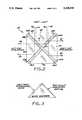
- FIGS. 2 and 3illustrate the polarization x-prism employed in the HVD of FIG. 1.
- FIG. 1A light weight binocular HVD 20 in accordance with the invention is shown in FIG. 1.
- the HVD 20uses a unique property of the "High Efficiency Low Glare X-Prism," described in the co-pending patent application of the same title, U.S. Ser No. 07/721,725, filed Jun. 21, 1991, 1991, by Ronald G. Hegg and assigned to a common assignee as the present application, to separate the left and right images from a common relay assembly.
- two CRTs 22 and 24 or other image sourcesare used to provide the scene to the observer.
- the light from one image sourceis polarized "p" and the light from the other source is polarized "s" by passing through a 1/4 wave plate or polarizing beamsplitter.
- the left eyeis "p" polarized while the right channel is “s” polarized.
- the image light from CRT 22is passed through a 1/4 wave plate 26 constructed to transmit the "s” polarized light component and to reflect the "p” polarized light component.
- the image light from CRT 24is passed through a 1/4 wave plate 28 constructed to transmit the "p” polarized light and to reflect the "s” polarized light.
- the resulting polarized left and right imagesare then projected through a common relay optical assembly comprising right angle beamsplitter 30 and lens 32 to a polarization x-prism 34 of the type described in the above-referenced pending patent application.
- the x-prism 34has the unique ability to separate the polarized light sending nearly all "p” light out one channel and nearly all "s” light out the other, as described more fully in connection with FIG. 2.
- the prism 34works like a channel separator.
- Lens 32is a graphical representation of the common relay assembly.
- the term “common”refers to the fact that both the left eye and right eye are sharing the same optical relay assembly.
- "Relay”describes a type of optical assembly to transfer an image to the observer while correcting for optical aberration. If the designer were to make the system a direct view apparatus, the relay assembly could be omitted entirely.
- the relay assemblymay be one lens or any number of lenses. In theory, any group of lenses can mathematically be represented by one single lens even though physical manufacturing constraints prohibit this in practice.
- the function of the relay assembly 32, in this application,is to transfer the image of the CRTs 22 and 24 to the observer.
- the relayis the assembly which adds the optical power, makes the image appear larger or smaller, and makes the image appear to be close to or far from the observer.
- the relay optics in the HVD assembly as shownis what "focuses" the image to the observer.
- Typical HVD unitshave a relay system which make the CRTs appear to be " focused” at or near infinity.
- the relay assembly 32can take various forms to provide the designer with a variety of displays.
- the respective imagesare then projected via the mirrors or optical combiners 36 and 38 to the observer's eyes.
- Another polarizing platemay be placed after the beamsplitter assembly to filter out any undesired crosstalk.
- Crosstalkis the appearance of the opposite channel's signal in the primary channel. For example, an inefficient coating may allow a ghost image of the left channel to appear in certain regions of the right channel. The amount of crosstalk is dependent on the FOV and coating quality. This crosstalk would be unacceptable to most viewers.
- the filtercould even be a coating applied directly to the exiting faces of the beamsplitter elements 44 and 48 (FIG. 2).
- the polarized filterwould allow light of only one polarization to pass through while attenuating all the other polarization.
- a "P" polarized filterwould be placed in the light path of rays 78 and 75 (FIG. 2). This would guarantee that only "S" polarized light would be transmitted to the left eye.
- the opposite arrangementwould be made for the right eye, (rays 72 and 82 in FIG. 2). These filters would be used to extinguish the opposing channel from appearing in the wrong eye.
- the polarization x-prism 34is shown in more detail in FIGS. 2 and 3.
- the x-prism 34comprises four similar right-angle triangles 42, 44, 46, 48, each having a "MacNeille" type dielectric coating formed on one leg and a half-wave plate bonded to the other leg.
- the respective legs carrying the coating and half-wave platemeet to define a right angle.
- a “half-wave plate”is a specific type of optical retarder.
- an optical retardercauses one of the polarizations of a beam of light to lag in phase behind the other.
- the relative phase of the two componentsUpon emerging from the retarder, the relative phase of the two components is different than it was initially and, thus, the polarization is different as well.
- a half-wave retarderintroduces a relative phase difference of ⁇ radians or 180° between the two waves. This has the effect of changing one polarization into another (i.e., "p" into “s” and “s” into “p”). See Optics, by Hecht and Zajac, 1976, pp. 246-248.
- the materialIn order to make one state lag behind the other, the material must have two different optical indices in the two directions. Such a material is called birefringent.
- a specific thickness of materialwill be a half-wave plate for a specific wavelength.
- the lightis typically centered around 543 nm which is the main peak of the CRT phosphor (P43), and hence the half-wave plate is tuned to about this wavelength.
- a half-wave plateis usually made from a thin slice of mica which is cleaved from the crystal. It can have a minimum thickness of about 60 microns. Therefore, in order to make a half-wave plate, the thickness of the material must conform to the following equation:
- n0, nethe two indices of the material
- ⁇the wavelength of light
- Micahas an index of 1.599 and 1.594. Therefore, if the 0th order is chosen along with the wavelength of 0.543 microns, the thickness works out to be 108.60 microns. Now since the material is actually situated 45° relative to the nominal input beam, the thickness of the plate would be only 76.79 microns.
- the "MacNeille” type coatingis a polarization-sensitive coating characterized in that incident "s" polarization light is predominately reflected and the incident "p” polarization light is transmitted. MacNeille type coatings are described, for example, in the "Handbook of Optics,” Walter G. Driscoll, Ed., 1978, at pages 8-74 and 8-75.
- the four triangular elements 42, 44, 46 and 48are typically made of glass, although other lens materials such as plastics may also be used.
- Schott SF6 or SFL6is the type of glass typically used since it has a high index ( ⁇ 1.8). High index glass works best for a wide FOV visor display. For a narrower FOV display, other glasses such as Schott BK7 (index ⁇ 1.52) can be used.
- the prism 34need not include four triangular pieces, since the triangular piece 46 may be omitted to save weight.
- the coatings 46A and 46Bcould then be applied to the outer surfaces of coatings 44A and 44B, respectively.
- the proper "MacNeille" coatingcan be designed with the following exemplary quarter-wave stack information.
- the quarter-wave stack of any interference dielectric coatingis a preferred thickness and structure whether two materials (designated by H and L referring to the high and low index material), are layered alternately so their effective optical thickness is a quarter of the wavelength of the nominal light radiation.
- a certain set of HL quarter-wave layerscan be so configured to give a "MacNeille" coating.
- the coatingsboth the 44 wave plates and the dielectric coatings applied to the prism elements are angularly dependent.
- the coatingis very efficient for near normal angles of incidence while nearly non-existent at 1° angle of incidence. This phenomenon is due to the fact the coatings are designed as 1/4 wave stacks of varying indexes of refraction. Since the stacks have a finite thickness, any ray of light entering the stack at an angle greater or lesser than the design angle, the coating will not reflect as efficiently.
- the actual lossdepends on many different variables, the wavelength and bandwidth of light, the purity of the coating materials, the 1/4 wave thickness accuracy and uniformity, as well as the quality of the prism surface and index of refraction. Based upon current technology and practice, Fields of View of 60° appear to be theoretically possible. With better controls and coating practices, even greater FOVs may be possible in the future. Varying the optical relay system, for instance adding a second relay system after the prism, could greatly increase the FOV achievable. Coating techniques are continuously expanding the angular bandwidth which is achievable.
- the beamsplitter 30 as shownmerely reflects 50% of the light at 90° while transmitting 50% of all light straight through regardless of polarization.
- the polarizers 26 and 28may be omitted if the beamsplitter 30 is replaced with a right angle polarized beamsplitter. This polarized prism would make use of the "MacNeille" coating so that only the appropriate polarization is passed.
- the "P” light of CRT 24 and the “S” light of the CRT 22would both be visible out the left side of prism 30.
- the "S” light from CRT 24would be reflected down through the bottom of the prism to the lens assembly 32.
- the use of the upper prism as a "MacNeille" right-angle, polarizing prismwould save the weight of the two polarizers 26 and 28.
Landscapes
- Physics & Mathematics (AREA)
- General Physics & Mathematics (AREA)
- Optics & Photonics (AREA)
- Engineering & Computer Science (AREA)
- Multimedia (AREA)
- Signal Processing (AREA)
Abstract
Description
d(nO-ne)=(2m+)λ/2
eff=(R.sub.s T.sub.p +R.sub.p T.sub.s)/2
Claims (11)
Priority Applications (1)
| Application Number | Priority Date | Filing Date | Title |
|---|---|---|---|
| US07/721,724US5198928A (en) | 1991-06-26 | 1991-06-26 | Light weight binocular helmet visor display |
Applications Claiming Priority (1)
| Application Number | Priority Date | Filing Date | Title |
|---|---|---|---|
| US07/721,724US5198928A (en) | 1991-06-26 | 1991-06-26 | Light weight binocular helmet visor display |
Publications (1)
| Publication Number | Publication Date |
|---|---|
| US5198928Atrue US5198928A (en) | 1993-03-30 |
Family
ID=24899043
Family Applications (1)
| Application Number | Title | Priority Date | Filing Date |
|---|---|---|---|
| US07/721,724Expired - Fee RelatedUS5198928A (en) | 1991-06-26 | 1991-06-26 | Light weight binocular helmet visor display |
Country Status (1)
| Country | Link |
|---|---|
| US (1) | US5198928A (en) |
Cited By (37)
| Publication number | Priority date | Publication date | Assignee | Title |
|---|---|---|---|---|
| WO1995021391A1 (en)* | 1994-02-07 | 1995-08-10 | Virtual I/O, Inc. | Intensified visual display |
| WO1996012207A1 (en)* | 1994-10-17 | 1996-04-25 | The University Of North Carolina At Chapel Hill | Optical path extender for compact imaging display systems |
| US5526022A (en) | 1993-01-06 | 1996-06-11 | Virtual I/O, Inc. | Sourceless orientation sensor |
| US5546200A (en)* | 1992-05-22 | 1996-08-13 | Thomson-Csf | Chromatic light separator and picture projector using a chromatic light separator |
| US5619377A (en) | 1992-02-07 | 1997-04-08 | Virtual I/O, Inc. | Optically corrected helmet mounted display |
| US5673146A (en)* | 1994-08-09 | 1997-09-30 | Kelly; Shawn L. | Binocular imaging system |
| US5748369A (en)* | 1992-10-29 | 1998-05-05 | Canon Kabushiki Kaisha | Polarizing beam splitter and an illuminating device provided with the same |
| US5751493A (en)* | 1996-11-15 | 1998-05-12 | Daewoo Electronics Co., Ltd. | Head-mounted display apparatus with a single image display device |
| US5751494A (en)* | 1995-12-18 | 1998-05-12 | Olympus Optical., Ltd. | Image display apparatus |
| US5808589A (en)* | 1994-08-24 | 1998-09-15 | Fergason; James L. | Optical system for a head mounted display combining high and low resolution images |
| US5864326A (en) | 1992-02-07 | 1999-01-26 | I-O Display Systems Llc | Depixelated visual display |
| US5903396A (en) | 1997-10-17 | 1999-05-11 | I/O Display Systems, Llc | Intensified visual display |
| US5903395A (en) | 1994-08-31 | 1999-05-11 | I-O Display Systems Llc | Personal visual display system |
| US5982343A (en)* | 1903-11-29 | 1999-11-09 | Olympus Optical Co., Ltd. | Visual display apparatus |
| US5991085A (en) | 1995-04-21 | 1999-11-23 | I-O Display Systems Llc | Head-mounted personal visual display apparatus with image generator and holder |
| US5991087A (en) | 1993-11-12 | 1999-11-23 | I-O Display System Llc | Non-orthogonal plate in a virtual reality or heads up display |
| US6008778A (en)* | 1997-03-04 | 1999-12-28 | Olympus Optical Co., Ltd. | Visual display apparatus |
| US6097544A (en)* | 1998-03-25 | 2000-08-01 | Balzers Hochvakuum Ag | Optical element with two optical systems having identical optical paths |
| US6097543A (en) | 1992-02-07 | 2000-08-01 | I-O Display Systems Llc | Personal visual display |
| US6115177A (en)* | 1999-04-06 | 2000-09-05 | Gateway, Inc. | Interactive 3-D viewing glasses |
| WO2000063738A1 (en)* | 1999-04-21 | 2000-10-26 | U.S. Precision Lens Incorporated | Optical systems for reflective lcd's |
| US6160666A (en) | 1994-02-07 | 2000-12-12 | I-O Display Systems Llc | Personal visual display system |
| US6239908B1 (en) | 1998-11-12 | 2001-05-29 | Shawn L. Kelly | Compact binocular imaging system using a single display |
| US20020051299A1 (en)* | 2000-08-08 | 2002-05-02 | Takayoshi Togino | Image display apparatus having three-dimensionally decentered opitical path |
| US6765727B1 (en)* | 2003-01-27 | 2004-07-20 | Delta Electronics, Inc. | Beam combiner |
| EP1175107A3 (en)* | 2000-07-18 | 2004-12-01 | Scalar Corporation | Stereoscopic display apparatus |
| US20080002859A1 (en)* | 2006-06-29 | 2008-01-03 | Himax Display, Inc. | Image inspecting device and method for a head-mounted display |
| US20090027772A1 (en)* | 2007-07-26 | 2009-01-29 | Real D | Head-Mounted Single Panel Stereoscopic Display |
| GB2451494A (en)* | 2007-08-01 | 2009-02-04 | Qinetiq Ltd | Polarimetric imaging apparatus |
| CN100468126C (en)* | 2006-04-21 | 2009-03-11 | 台达电子工业股份有限公司 | Light-combining components of projection systems |
| US20090290222A1 (en)* | 2007-06-20 | 2009-11-26 | Canon Kabushiki Kaisha | Image observation apparatus and image observation system |
| US8213064B2 (en)* | 2000-03-28 | 2012-07-03 | Elbit Systems Ltd. | Personal display system with extended field of view |
| US20160041387A1 (en)* | 2013-03-28 | 2016-02-11 | Bae Systems Plc | Improvements in and relating to displays |
| CN108267859A (en)* | 2017-01-12 | 2018-07-10 | 胡大文 | One kind is used to show the multimedia display equipment of 3D |
| US10353213B2 (en)* | 2016-12-08 | 2019-07-16 | Darwin Hu | See-through display glasses for viewing 3D multimedia |
| EP3588167A1 (en)* | 2018-06-28 | 2020-01-01 | Samsung Electronics Co., Ltd. | Display apparatus |
| US11163177B2 (en)* | 2016-12-08 | 2021-11-02 | Darwin Hu | See-through display glasses with single imaging source |
Citations (7)
| Publication number | Priority date | Publication date | Assignee | Title |
|---|---|---|---|---|
| US2182142A (en)* | 1937-02-12 | 1939-12-05 | Technicolor Motion Picture | Dividing polarized light beams |
| US2449287A (en)* | 1946-09-23 | 1948-09-14 | Merrill M Flood | Polarizing beam-splitting prism |
| US2811077A (en)* | 1951-08-21 | 1957-10-29 | Pola Lux Ges Fur Blendschutz U | Stereo projection apparatus |
| WO1985004961A1 (en)* | 1984-04-16 | 1985-11-07 | Hughes Aircraft Company | Biocular holographic helmet mounted display |
| US4559556A (en)* | 1983-11-09 | 1985-12-17 | Wilkins Vaughn D | System for viewing three dimensional images |
| US4623219A (en)* | 1985-04-15 | 1986-11-18 | The United States Of America As Represented By The Secretary Of The Navy | Real-time high-resolution 3-D large-screen display using laser-activated liquid crystal light valves |
| US4670744A (en)* | 1985-03-14 | 1987-06-02 | Tektronix, Inc. | Light reflecting three-dimensional display system |
- 1991
- 1991-06-26USUS07/721,724patent/US5198928A/ennot_activeExpired - Fee Related
Patent Citations (7)
| Publication number | Priority date | Publication date | Assignee | Title |
|---|---|---|---|---|
| US2182142A (en)* | 1937-02-12 | 1939-12-05 | Technicolor Motion Picture | Dividing polarized light beams |
| US2449287A (en)* | 1946-09-23 | 1948-09-14 | Merrill M Flood | Polarizing beam-splitting prism |
| US2811077A (en)* | 1951-08-21 | 1957-10-29 | Pola Lux Ges Fur Blendschutz U | Stereo projection apparatus |
| US4559556A (en)* | 1983-11-09 | 1985-12-17 | Wilkins Vaughn D | System for viewing three dimensional images |
| WO1985004961A1 (en)* | 1984-04-16 | 1985-11-07 | Hughes Aircraft Company | Biocular holographic helmet mounted display |
| US4670744A (en)* | 1985-03-14 | 1987-06-02 | Tektronix, Inc. | Light reflecting three-dimensional display system |
| US4623219A (en)* | 1985-04-15 | 1986-11-18 | The United States Of America As Represented By The Secretary Of The Navy | Real-time high-resolution 3-D large-screen display using laser-activated liquid crystal light valves |
Cited By (53)
| Publication number | Priority date | Publication date | Assignee | Title |
|---|---|---|---|---|
| US5982343A (en)* | 1903-11-29 | 1999-11-09 | Olympus Optical Co., Ltd. | Visual display apparatus |
| US5642227A (en) | 1992-02-07 | 1997-06-24 | Virtual I/O, Inc. | Optical correction for virtual reality and heads up displays |
| US5864326A (en) | 1992-02-07 | 1999-01-26 | I-O Display Systems Llc | Depixelated visual display |
| US5619377A (en) | 1992-02-07 | 1997-04-08 | Virtual I/O, Inc. | Optically corrected helmet mounted display |
| US6097543A (en) | 1992-02-07 | 2000-08-01 | I-O Display Systems Llc | Personal visual display |
| US5673151A (en)* | 1992-02-07 | 1997-09-30 | Virtual I/O | Image correction in virtual reality and heads up displays |
| US5949583A (en) | 1992-02-07 | 1999-09-07 | I-O Display Systems Llc | Head-mounted display with image generator, fold mirror and mirror for transmission to the eye position of the user |
| US5546200A (en)* | 1992-05-22 | 1996-08-13 | Thomson-Csf | Chromatic light separator and picture projector using a chromatic light separator |
| US5748369A (en)* | 1992-10-29 | 1998-05-05 | Canon Kabushiki Kaisha | Polarizing beam splitter and an illuminating device provided with the same |
| US5526022A (en) | 1993-01-06 | 1996-06-11 | Virtual I/O, Inc. | Sourceless orientation sensor |
| US5991087A (en) | 1993-11-12 | 1999-11-23 | I-O Display System Llc | Non-orthogonal plate in a virtual reality or heads up display |
| WO1995021391A1 (en)* | 1994-02-07 | 1995-08-10 | Virtual I/O, Inc. | Intensified visual display |
| US6160666A (en) | 1994-02-07 | 2000-12-12 | I-O Display Systems Llc | Personal visual display system |
| US5673146A (en)* | 1994-08-09 | 1997-09-30 | Kelly; Shawn L. | Binocular imaging system |
| US5808589A (en)* | 1994-08-24 | 1998-09-15 | Fergason; James L. | Optical system for a head mounted display combining high and low resolution images |
| US5903395A (en) | 1994-08-31 | 1999-05-11 | I-O Display Systems Llc | Personal visual display system |
| WO1996012207A1 (en)* | 1994-10-17 | 1996-04-25 | The University Of North Carolina At Chapel Hill | Optical path extender for compact imaging display systems |
| US5777795A (en)* | 1994-10-17 | 1998-07-07 | University Of North Carolina | Optical path extender for compact imaging display systems |
| US5610765A (en)* | 1994-10-17 | 1997-03-11 | The University Of North Carolina At Chapel Hill | Optical path extender for compact imaging display systems |
| US5991085A (en) | 1995-04-21 | 1999-11-23 | I-O Display Systems Llc | Head-mounted personal visual display apparatus with image generator and holder |
| US5751494A (en)* | 1995-12-18 | 1998-05-12 | Olympus Optical., Ltd. | Image display apparatus |
| US5751493A (en)* | 1996-11-15 | 1998-05-12 | Daewoo Electronics Co., Ltd. | Head-mounted display apparatus with a single image display device |
| US6008778A (en)* | 1997-03-04 | 1999-12-28 | Olympus Optical Co., Ltd. | Visual display apparatus |
| US5903396A (en) | 1997-10-17 | 1999-05-11 | I/O Display Systems, Llc | Intensified visual display |
| US6097544A (en)* | 1998-03-25 | 2000-08-01 | Balzers Hochvakuum Ag | Optical element with two optical systems having identical optical paths |
| US6239908B1 (en) | 1998-11-12 | 2001-05-29 | Shawn L. Kelly | Compact binocular imaging system using a single display |
| US6115177A (en)* | 1999-04-06 | 2000-09-05 | Gateway, Inc. | Interactive 3-D viewing glasses |
| US6490087B1 (en) | 1999-04-21 | 2002-12-03 | U.S. Precision Lens Incorporated | Optical systems for reflective LCD's |
| WO2000063738A1 (en)* | 1999-04-21 | 2000-10-26 | U.S. Precision Lens Incorporated | Optical systems for reflective lcd's |
| US8213064B2 (en)* | 2000-03-28 | 2012-07-03 | Elbit Systems Ltd. | Personal display system with extended field of view |
| KR100843429B1 (en)* | 2000-07-18 | 2008-07-03 | 스카라 가부시키가이샤 | A Head-mount Type Display Device for Three Dimensional View, Endoscope and Microscope Using Thereof |
| EP1175107A3 (en)* | 2000-07-18 | 2004-12-01 | Scalar Corporation | Stereoscopic display apparatus |
| US6833952B2 (en)* | 2000-07-18 | 2004-12-21 | Scalar Corporation | Stereoscopic display apparatus, endscope and microscope both using the apparatus |
| US20020051299A1 (en)* | 2000-08-08 | 2002-05-02 | Takayoshi Togino | Image display apparatus having three-dimensionally decentered opitical path |
| US6501602B2 (en)* | 2000-08-08 | 2002-12-31 | Olympus Optical Co., Ltd. | Image display apparatus having three-dimensionally decentered optical path |
| US20040145812A1 (en)* | 2003-01-27 | 2004-07-29 | Sean Chang | Beam combiner |
| US6765727B1 (en)* | 2003-01-27 | 2004-07-20 | Delta Electronics, Inc. | Beam combiner |
| CN100468126C (en)* | 2006-04-21 | 2009-03-11 | 台达电子工业股份有限公司 | Light-combining components of projection systems |
| US20080002859A1 (en)* | 2006-06-29 | 2008-01-03 | Himax Display, Inc. | Image inspecting device and method for a head-mounted display |
| US8170325B2 (en)* | 2006-06-29 | 2012-05-01 | Himax Display, Inc. | Image inspecting device and method for a head-mounted display |
| US20090290222A1 (en)* | 2007-06-20 | 2009-11-26 | Canon Kabushiki Kaisha | Image observation apparatus and image observation system |
| US7982972B2 (en)* | 2007-06-20 | 2011-07-19 | Canon Kabushiki Kaisha | Image observation apparatus and image observation system |
| US20090027772A1 (en)* | 2007-07-26 | 2009-01-29 | Real D | Head-Mounted Single Panel Stereoscopic Display |
| GB2451494B (en)* | 2007-08-01 | 2011-06-08 | Qinetiq Ltd | Polarimetric imaging apparatus |
| GB2451494A (en)* | 2007-08-01 | 2009-02-04 | Qinetiq Ltd | Polarimetric imaging apparatus |
| US20160041387A1 (en)* | 2013-03-28 | 2016-02-11 | Bae Systems Plc | Improvements in and relating to displays |
| US9946069B2 (en)* | 2013-03-28 | 2018-04-17 | Bae Systems Plc | Displays |
| US10353213B2 (en)* | 2016-12-08 | 2019-07-16 | Darwin Hu | See-through display glasses for viewing 3D multimedia |
| US11163177B2 (en)* | 2016-12-08 | 2021-11-02 | Darwin Hu | See-through display glasses with single imaging source |
| CN108267859A (en)* | 2017-01-12 | 2018-07-10 | 胡大文 | One kind is used to show the multimedia display equipment of 3D |
| CN108267859B (en)* | 2017-01-12 | 2021-08-20 | 胡大文 | Display equipment for displaying 3D multimedia |
| EP3588167A1 (en)* | 2018-06-28 | 2020-01-01 | Samsung Electronics Co., Ltd. | Display apparatus |
| US11243396B2 (en) | 2018-06-28 | 2022-02-08 | Samsung Electronics Co., Ltd. | Display apparatus |
Similar Documents
| Publication | Publication Date | Title |
|---|---|---|
| US5198928A (en) | Light weight binocular helmet visor display | |
| US5245472A (en) | High-efficiency, low-glare X-prism | |
| US5347644A (en) | Three-dimensional image display device and systems and methods for implementation thereof | |
| US10739611B2 (en) | 3D projection system | |
| EP0477889B1 (en) | Full color three-dimensional display system | |
| EP0349692B1 (en) | Stereoscopic display | |
| EP3839608B1 (en) | Near-eye display apparatus | |
| US20070070508A1 (en) | Collimating optical member for real world simulation | |
| JPH03211992A (en) | All color three-dimensional projection display | |
| US7479933B2 (en) | Stereoscopic display apparatus particularly useful with LCD projectors | |
| CN106990667B (en) | Stereoscopic projection imaging device and system | |
| US20070146880A1 (en) | Optical device for splitting an incident light into simultaneously spectrally separated and orthogonally polarized light beams having complementary primary color bands | |
| US20100171890A1 (en) | Projection stereoscopic display | |
| JP2018522290A (en) | Stereoscopic 3D projection system with improved level of optical light efficiency | |
| KR101641479B1 (en) | Apparatus for displaying a stereoscopic image | |
| US20240061248A1 (en) | Anamorphic directional illumination device | |
| CN116679476B (en) | Optical device, head mounted display device and adjustment method of head mounted display device | |
| WO1999052269A2 (en) | Compact projector | |
| GB2222892A (en) | Optical display apparatus | |
| CN114902117B (en) | Polarization conversion system, passive linear polarization 3D glasses and linear polarization 3D system | |
| US7145719B2 (en) | Optical cores and projection systems containing the optical core | |
| US20230418034A1 (en) | Anamorphic directional illumination device | |
| JP2526652B2 (en) | Liquid crystal projection type stereoscopic display device | |
| KR101939939B1 (en) | Image conversion for stereoscopic imagery | |
| CN116679477B (en) | Optical device, head mounted display device and adjustment method of head mounted display device |
Legal Events
| Date | Code | Title | Description |
|---|---|---|---|
| AS | Assignment | Owner name:HUGHES AIRCRAFT COMPANY, CALIFORNIA Free format text:ASSIGNMENT OF ASSIGNORS INTEREST.;ASSIGNOR:CHAUVIN, DEWEY J.;REEL/FRAME:005766/0638 Effective date:19910624 | |
| REMI | Maintenance fee reminder mailed | ||
| FEPP | Fee payment procedure | Free format text:PAYOR NUMBER ASSIGNED (ORIGINAL EVENT CODE: ASPN); ENTITY STATUS OF PATENT OWNER: LARGE ENTITY | |
| FPAY | Fee payment | Year of fee payment:4 | |
| SULP | Surcharge for late payment | ||
| FEPP | Fee payment procedure | Free format text:PAYER NUMBER DE-ASSIGNED (ORIGINAL EVENT CODE: RMPN); ENTITY STATUS OF PATENT OWNER: LARGE ENTITY | |
| FEPP | Fee payment procedure | Free format text:PAYOR NUMBER ASSIGNED (ORIGINAL EVENT CODE: ASPN); ENTITY STATUS OF PATENT OWNER: LARGE ENTITY Free format text:PAYER NUMBER DE-ASSIGNED (ORIGINAL EVENT CODE: RMPN); ENTITY STATUS OF PATENT OWNER: LARGE ENTITY | |
| FPAY | Fee payment | Year of fee payment:8 | |
| REMI | Maintenance fee reminder mailed | ||
| LAPS | Lapse for failure to pay maintenance fees | ||
| STCH | Information on status: patent discontinuation | Free format text:PATENT EXPIRED DUE TO NONPAYMENT OF MAINTENANCE FEES UNDER 37 CFR 1.362 | |
| FP | Lapsed due to failure to pay maintenance fee | Effective date:20050330 |