US5198796A - Outbound signal detector system and method - Google Patents
Outbound signal detector system and methodDownload PDFInfo
- Publication number
- US5198796A US5198796AUS07/722,134US72213491AUS5198796AUS 5198796 AUS5198796 AUS 5198796AUS 72213491 AUS72213491 AUS 72213491AUS 5198796 AUS5198796 AUS 5198796A
- Authority
- US
- United States
- Prior art keywords
- set forth
- signal detection
- outbound
- approximately
- degrees
- Prior art date
- Legal status (The legal status is an assumption and is not a legal conclusion. Google has not performed a legal analysis and makes no representation as to the accuracy of the status listed.)
- Expired - Lifetime
Links
Images

Classifications
- H—ELECTRICITY
- H04—ELECTRIC COMMUNICATION TECHNIQUE
- H04B—TRANSMISSION
- H04B3/00—Line transmission systems
- H04B3/54—Systems for transmission via power distribution lines
- H04B3/542—Systems for transmission via power distribution lines the information being in digital form
- H—ELECTRICITY
- H02—GENERATION; CONVERSION OR DISTRIBUTION OF ELECTRIC POWER
- H02J—CIRCUIT ARRANGEMENTS OR SYSTEMS FOR SUPPLYING OR DISTRIBUTING ELECTRIC POWER; SYSTEMS FOR STORING ELECTRIC ENERGY
- H02J13/00—Circuit arrangements for providing remote indication of network conditions, e.g. an instantaneous record of the open or closed condition of each circuitbreaker in the network; Circuit arrangements for providing remote control of switching means in a power distribution network, e.g. switching in and out of current consumers by using a pulse code signal carried by the network
- H02J13/00006—Circuit arrangements for providing remote indication of network conditions, e.g. an instantaneous record of the open or closed condition of each circuitbreaker in the network; Circuit arrangements for providing remote control of switching means in a power distribution network, e.g. switching in and out of current consumers by using a pulse code signal carried by the network characterised by information or instructions transport means between the monitoring, controlling or managing units and monitored, controlled or operated power network element or electrical equipment
- H02J13/00007—Circuit arrangements for providing remote indication of network conditions, e.g. an instantaneous record of the open or closed condition of each circuitbreaker in the network; Circuit arrangements for providing remote control of switching means in a power distribution network, e.g. switching in and out of current consumers by using a pulse code signal carried by the network characterised by information or instructions transport means between the monitoring, controlling or managing units and monitored, controlled or operated power network element or electrical equipment using the power network as support for the transmission
- H02J13/00009—Circuit arrangements for providing remote indication of network conditions, e.g. an instantaneous record of the open or closed condition of each circuitbreaker in the network; Circuit arrangements for providing remote control of switching means in a power distribution network, e.g. switching in and out of current consumers by using a pulse code signal carried by the network characterised by information or instructions transport means between the monitoring, controlling or managing units and monitored, controlled or operated power network element or electrical equipment using the power network as support for the transmission using pulsed signals
- H—ELECTRICITY
- H04—ELECTRIC COMMUNICATION TECHNIQUE
- H04B—TRANSMISSION
- H04B3/00—Line transmission systems
- H04B3/02—Details
- H04B3/32—Reducing cross-talk, e.g. by compensating
- H—ELECTRICITY
- H04—ELECTRIC COMMUNICATION TECHNIQUE
- H04B—TRANSMISSION
- H04B2203/00—Indexing scheme relating to line transmission systems
- H04B2203/54—Aspects of powerline communications not already covered by H04B3/54 and its subgroups
- H04B2203/5404—Methods of transmitting or receiving signals via power distribution lines
- H04B2203/5416—Methods of transmitting or receiving signals via power distribution lines by adding signals to the wave form of the power source
- H—ELECTRICITY
- H04—ELECTRIC COMMUNICATION TECHNIQUE
- H04B—TRANSMISSION
- H04B2203/00—Indexing scheme relating to line transmission systems
- H04B2203/54—Aspects of powerline communications not already covered by H04B3/54 and its subgroups
- H04B2203/5404—Methods of transmitting or receiving signals via power distribution lines
- H04B2203/542—Methods of transmitting or receiving signals via power distribution lines using zero crossing information
- H—ELECTRICITY
- H04—ELECTRIC COMMUNICATION TECHNIQUE
- H04B—TRANSMISSION
- H04B2203/00—Indexing scheme relating to line transmission systems
- H04B2203/54—Aspects of powerline communications not already covered by H04B3/54 and its subgroups
- H04B2203/5462—Systems for power line communications
- H04B2203/5466—Systems for power line communications using three phases conductors
- H—ELECTRICITY
- H04—ELECTRIC COMMUNICATION TECHNIQUE
- H04B—TRANSMISSION
- H04B2203/00—Indexing scheme relating to line transmission systems
- H04B2203/54—Aspects of powerline communications not already covered by H04B3/54 and its subgroups
- H04B2203/5462—Systems for power line communications
- H04B2203/5483—Systems for power line communications using coupling circuits
- H04B2203/5487—Systems for power line communications using coupling circuits cables
- H—ELECTRICITY
- H04—ELECTRIC COMMUNICATION TECHNIQUE
- H04B—TRANSMISSION
- H04B2203/00—Indexing scheme relating to line transmission systems
- H04B2203/54—Aspects of powerline communications not already covered by H04B3/54 and its subgroups
- H04B2203/5462—Systems for power line communications
- H04B2203/5495—Systems for power line communications having measurements and testing channel
- Y—GENERAL TAGGING OF NEW TECHNOLOGICAL DEVELOPMENTS; GENERAL TAGGING OF CROSS-SECTIONAL TECHNOLOGIES SPANNING OVER SEVERAL SECTIONS OF THE IPC; TECHNICAL SUBJECTS COVERED BY FORMER USPC CROSS-REFERENCE ART COLLECTIONS [XRACs] AND DIGESTS
- Y02—TECHNOLOGIES OR APPLICATIONS FOR MITIGATION OR ADAPTATION AGAINST CLIMATE CHANGE
- Y02E—REDUCTION OF GREENHOUSE GAS [GHG] EMISSIONS, RELATED TO ENERGY GENERATION, TRANSMISSION OR DISTRIBUTION
- Y02E60/00—Enabling technologies; Technologies with a potential or indirect contribution to GHG emissions mitigation
- Y—GENERAL TAGGING OF NEW TECHNOLOGICAL DEVELOPMENTS; GENERAL TAGGING OF CROSS-SECTIONAL TECHNOLOGIES SPANNING OVER SEVERAL SECTIONS OF THE IPC; TECHNICAL SUBJECTS COVERED BY FORMER USPC CROSS-REFERENCE ART COLLECTIONS [XRACs] AND DIGESTS
- Y04—INFORMATION OR COMMUNICATION TECHNOLOGIES HAVING AN IMPACT ON OTHER TECHNOLOGY AREAS
- Y04S—SYSTEMS INTEGRATING TECHNOLOGIES RELATED TO POWER NETWORK OPERATION, COMMUNICATION OR INFORMATION TECHNOLOGIES FOR IMPROVING THE ELECTRICAL POWER GENERATION, TRANSMISSION, DISTRIBUTION, MANAGEMENT OR USAGE, i.e. SMART GRIDS
- Y04S40/00—Systems for electrical power generation, transmission, distribution or end-user application management characterised by the use of communication or information technologies, or communication or information technology specific aspects supporting them
- Y04S40/12—Systems for electrical power generation, transmission, distribution or end-user application management characterised by the use of communication or information technologies, or communication or information technology specific aspects supporting them characterised by data transport means between the monitoring, controlling or managing units and monitored, controlled or operated electrical equipment
- Y04S40/121—Systems for electrical power generation, transmission, distribution or end-user application management characterised by the use of communication or information technologies, or communication or information technology specific aspects supporting them characterised by data transport means between the monitoring, controlling or managing units and monitored, controlled or operated electrical equipment using the power network as support for the transmission
Definitions
- This inventionrelates to carrier wave intelligence systems in general and, more particularly, to apparatus useful in detecting and extracting information or intelligence transmitted outbound to electricity meters and the like over electric power distribution networks from a central site.
- the carrier waveis the voltage wave of an electrical power distribution system or network.
- Such systemsare described in U.S. Pat. Nos. 4,106,007, 4,218,655, and 4,400,688 to Johnston et al, and 4,105,897 to Stratton et al, which patents are incorporated herein by reference.
- Each customer serviceconstitutes a branch in the distribution feeder, and the branching is so extensive that it is impractical to provide filter and by-pass circuitry at each branch point.
- the distribution networkis not an attractive medium for conventional communications due to the attenuation and dispersion of the signals and because noise levels tend to be high. To overcome the high noise levels, it is generally necessary to use narrow band filtering, error-detecting and error-correcting codes, and relatively high signal power levels at low bit rates.
- the modulation signal which carries the informationpreferably should have dominant positive and negative sequence components. This implies that the outbound modulation signal should not appear on all three phases simultaneously at equal strength and phase relationship.
- At least on outbound signal detector systemlooks for signals disposed on the voltage carrier at the -10° and the +30° points on the waveform.
- a fixed signal thresholdis typically used with that system to determine the presence or absence of signal at the detection points. This system has shown good performance under various conditions, but it could be improved.
- At least one area of possible improvementconcerns coping with the dynamics of the distribution network.
- outbound signalingcauses transient oscillations in the waveform which depend on the capacitance and load on the network at that time. Variation in loads results in a great variation in these transients, with resulting distortion of the waveform. Since loads on power distribution networks vary with time of day, this means that the reliability of the outbound signal detector can also vary with the time of day.
- a second possible area of improvementrelates to crosstalk.
- the voltage in any one phaseis related to or coupled to the voltages in the other two phases. This leads to crosstalk. It should also be realized that the source configuration of the power distribution network also affects the severity of crosstalk.
- an outbound signal detection systemcapable of extracting the outbound signal under various dynamic load conditions.
- Another objectis the provision of such a system capable of rejecting crosstalk under various dynamic load conditions.
- a third objectis the provision of such a system which is relatively simple and inexpensive in construction.
- a fourth objectis the provision of such a system which adapts to the dynamics of the power distribution network.
- the method of signal detection of the present inventionis designed for use in a communication system in which outbound information is carried by cyclic waveforms over an electric power distribution network.
- the informationis transmitted in the form of multi-bit messages carried by the cyclic waveform.
- the methodincludes obtaining signal data by sampling the cyclic waveform over a predetermined portion of successive cycles, and dividing the predetermined portion into a plurality of predetermined ranges. From a predetermined number of bits at the start of each message, the particular predetermined range which contains the greatest signal strength is selected. For the remaining bits of the message, only those samples in the selected range are analyzed to detect the outbound message.
- the signal detection system of the present inventionincludes circuitry for obtaining signal data by sampling the cyclic waveform over a predetermined portion of successive cycles, the predetermined portion being divided into a plurality of predetermined ranges. It also includes circuitry responsive to the signal data for examining the signal data and, from a predetermined number of bits at the start of each message, selecting the particular predetermined range which contains the greatest signal strength.
- the range selecting circuitryis responsive to the selection of a particular predetermined range to analyze only those samples in the selected range, for the remaining bits of the message, to detect the outbound message.
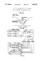
- FIG. 1is a graphical representation of the carrier waveform with signal imposed thereon of a communication system which uses the AC power waveform of an electric power distribution system as a carrier;
- FIG. 1Ais an enlarged portion of FIG. 1;
- FIG. 2is a block diagram of the signal detector system of the present invention.
- FIG. 3Ais a graphical representation of the rectified waveform of FIG. 1 used in the present invention to detect signals imposed upon the carrier;
- FIG. 3Bis an enlarged portion of FIG. 1;
- FIG. 4is a block diagram illustrating data compression in the present invention.
- the present inventionis designed for use in connection with a communication system which uses cyclic waveforms of the electric power distribution network to carry information in the form of multi-bit messages.
- Typical waveforms in such a communication systemare illustrated in FIGS. 1 and 1A.
- the outbound signalis a modulation which is injected on the 60 Hz AC power waveform 11.
- the basic waveshape of the injected signalis a transient oscillatory waveform 13.
- Waveform 13is located approximately next to a zero crossing 15 of the 60 Hz AC power waveform so that (ideally) the first two lobes of the waveform straddle the zero crossing.
- These lobesare detected by measuring the time difference, delta-T, between the crossing of a predetermined point by the modulated waveform and by the unmodulated waveform. Normally this is done by comparing the crossing times in adjacent half-cycles.
- cross-talkarises in such a system due to the cross coupling of the phases on a three-phase system of the AC power distribution system.
- the cross-talk modulation waveformis approximately located at multiples of thirty degrees both leading and lagging from the in-phase modulation illustrated in FIG. 1A.
- every outbound messageis preceded by a fixed data pattern, called the preamble, which is used to avoid false synchronization due to noise.
- this patternis a "0" synchronization bit, a "1110010” Barker code, and a "0" stop bit.
- the prior technique for synchronizing the detectoris illustrated in FIG. 1A.
- the signal detectordetermines the presence of a signal by testing only two points on the waveform, typically ten degrees before and thirty degrees after the zero crossing.
- the prior detectormonitors the signal measured every half-cycle of the AC power waveform and decides to synchronize the bit framing based on the one sample (two points) of data. If the environment at the detector is noisy, then the detector will constantly be falsely synchronized by noise that meets the minimum signal level requirement (e.g., twenty microseconds of signal) and is a "0" bit. After the initial framing, the prior detector measures the data from each successive frame and determines if the measured signal is a "0" or a "1" bit. After false synchronization, the detector will normally recover during the preamble by testing each successive bit for correctness and aborting the message framing if an erroneous bit is determined. However, during recovery, valid synchronizations are sometimes missed.
- the signal detecting system of the present inventionis illustrated in FIG. 2.
- the systemincludes a microcontroller 21 under software control, a 12 MHz oscillator 23, a divide-by-12 divider 25, a 16-bit counter 27, and a 16-bit latch 29.
- the output of the oscillatoris provided through the divider to step counter 27.
- the output of the counteris supplied to latch 29, where it is latched upon receipt of a suitable trigger input, described below.
- This arrangementis used to measure the times, discussed above, so that the microcontroller can calculate the time differences, the delta-Ts, to detect the presence of signals on the waveform.
- the outbound detector itself(labelled 31) is connected to microcontroller 21 to provide the trigger signal to latch 29.
- Detector 31includes an op-amp voltage follower 33 for providing a tracking reference, a multiplying digital-to-analog converter (DAC) 35, and a comparator 37.
- DACdigital-to-analog converter
- the 60 Hz AC power waveformis full-wave rectified by a rectifier 41.
- the rectified waveform 43which is the output of rectifier 41, is shown in FIG. 3A.
- This outputis filtered by a suitable RC network 45 to provide a DC reference voltage VREF, which is proportional to the average of the AC rectified line voltage.
- This DC reference voltageis supplied to voltage follower 33, which buffers the voltage.
- the output of voltage follower 33provides the reference for the 8-bit DAC 35. It is preferred that the DAC control register be memory mapped by on-chip decoder logic and controlled by microcontroller 21. The microcontroller accesses the six most significant bits of the DAC, while the lower two bits are controlled by the comparator and used for hysteresis.
- the DAC output voltage VOUTis compared by comparator 37 to a scaled fullwave rectified AC line voltage VRWR obtained from rectifier 41.
- the output of the comparatorprovides the trigger signal to latch 29 in the microcontroller.
- the polarity of the trigger edgeis controlled by a one-bit latch 49.
- the DAC voltage VOUTis stepped at values which correspond to points between -50 degrees to 50 degrees, referenced to the zero crossing on the unrectified AC waveform.
- ten degree stepsare shown in FIG. 3B for purposes of illustration, it is preferred that the steps be five degree steps, so that counts are latched into latch 29 every five degrees between -50 degrees and +50 degrees on the waveform.
- the microcontrollerrecords these counts, and thereby can detect time differences, delta-Ts, from cycle to cycle.
- trigger pointsare set by microcontroller 21, through DAC 35, to capture data in a free running counter/timer consisting of counter 27 and latch 29.
- the captured timer data for each five degree segmentis stored for later processing.
- the useful signalis extracted by comparing the segment timings of adjacent cycles of the AC waveform. Since the receiving device can be connected across the AC power line without regard to polarity, this extraction is done every half cycle of the 60 Hz AC waveform, or 120 times per second.
- the frequency of the outbound signalwill vary depending on the inductive and resistive loading and on the amount of power factor correcting shunt capacitors on the network at any given time. Since the outbound signal frequency is dynamic and varies depending on load, the outbound detector system of the present invention must be able to adapt to the changes in frequency. This requires that different groupings of measured segments be used to track the peak of the waveform for the varying frequencies.
- these predetermined rangesdo not correspond particularly well with the fixed -10/+30 range of the prior art systems illustrated in FIG. 1A except in one instance.
- the present systemis, therefore, much more versatile than the prior art.
- the microcontrollerrecords the times, as set forth above, and groups them into the ranges set forth above.
- the signal for any particular rangeis the summation of the signals for each of the five degree segments measured with the range. This sum is stored in the microcontroller for each range and each bit of the preamble.
- the microcontrollerstores eight sets of signal data (one for each predetermined range).
- the microcontrollercan lock onto the peak signal for that detector location at that particular time. More specifically, the microcontroller locks on to the peak signal during the preamble of the multi-bit message.
- the system of the present inventionstores range data for thirty-six half-cycles (t-0 to t-35). The microcontroller software, therefore, keeps a history of the last thirty-six measurements for each of the predetermined ranges. These measurements are tested every half cycle of the 60 Hz AC power waveform.
- the datais compressed or pretested before storage in shift registers.
- This data compression for a single rangeis illustrated in FIG. 4. It should be noted that for the particular preamble discussed above, the measurements for a valid preamble should result in a positive signal on half cycles t-0, t-4, t-12, t-16, t-22, t-26 and t-32. Negative signal will be measured on half cycles t-2, t-8, t-14, t-20, t-24 and t-28 for a valid preamble. Moreover, the absolute value of the signal on half cycle t-32 (the "0" sync bit) must be greater than the nominal noise threshold. This threshold was experimentally adjusted to twenty microseconds. Moreover, for a useful communications system, the average of the absolute values of the signals used must be greater than the nominal noise threshold. The data compression of FIG. 4 takes into account these criteria.
- the summationis also supplied through an absolute value block 55 to a second comparator 57 which compares the sum with the predetermined threshold of twenty microseconds.
- the output of comparator 57is also a bit decision reflecting whether the detected signal exceeds the noise threshold. This bit decision is stored in a threshold bit buffer 59 for each four half cycles.
- the third criteriawhether the average of the absolute values of the signals used exceed the nominal noise threshold, is determined in part by the absolute value of the signal being supplied from block 55 to a summer 63. There it is added to the previous average and divided by two to give a pseudo average which reflects the average of the signal over the nine bits of the preamble.
- This processis applied to each of the predetermined ranges during the detection of the preamble. It provides an effective filter to impulse noise, a mechanism for identifying the peak signal frequency, and allows very weak signals to be locked onto.
- the outbound detectoris properly synchronized to the outbound message and can begin bit framing on the next half cycle. At that point and for the rest of that particular message, the detector examines only those samples in the range which has been selected as having the maximum average signal strength, based upon the analysis of the signal strength in each range throughout the preamble.
- each detector of the present inventionUpon receipt of the preamble of the next message the process is repeated so that the system adapts to the network characteristics for each message. Note that these characteristics may vary from location to location. Since each detector of the present invention adapts solely based upon its local conditions, the adaptation of each separate detector is essentially independent of all other detectors.
- the power utility distribution systemis composed of three phases which are sixty degrees out of phase with respect to each other.
- the communication system with which the present detection scheme operatesis designed to inject outbound signal onto each of these phases independently and also across phase pairs independently. This is done to allow access to outbound receivers which may be connected on any phase or phase combination.
- phase combinationswhich use the phase.
- This signalwill be at a reduced amplitude and be located either thirty degrees before or thirty degrees after the normal in-phase signal.
- This cross-talk signalis the same as in-phase signals and will vary in location with respect to zero crossing just as in-phase signals will vary.
- the cross-talk signalswill overlap into the in-phase signal ranges, thereby causing the in-phase signal detector to detect and synchronize with the cross-talk signal.
- the amplitude of the signal in the in-phase rangesis normally less than that which can be measured in the cross-talk regions.
- the in-phase signal which is detectedis rejected, as overlap from cross-talk, by monitoring the above cross-talk detection ranges, applying the sam pattern recognition criteria for synchronization described above, and rejecting in-phase synchronization when cross-talk signal strength is greater than in-phase signal strength.
Landscapes
- Engineering & Computer Science (AREA)
- Power Engineering (AREA)
- Computer Networks & Wireless Communication (AREA)
- Signal Processing (AREA)
- Cable Transmission Systems, Equalization Of Radio And Reduction Of Echo (AREA)
Abstract
Description
______________________________________ Very High Frequency: -20/-5 range 720 Hz with first peak at -20 deg. High Frequency: -15/+5 range 540 Hz with first peak at -15 deg. -5/+15 range 540 Hz with first peak at -5 deg. Medium Frequency: -15/+15 range 360 Hz with first peak at -15 deg. +5/+35 range 360 Hz with first peak at +5 deg. -5/+30 range 308 Hz with first peak at -5 deg. Low Frequency: -10/+30 range 270 Hz with first peak at -10 deg. -5/+35 range 270 Hz with first peak at -5 deg. ______________________________________
______________________________________ High Frequency Leading: -45/-25 range 540 Hz with first peak at -45 deg. -45/-20 range 432 Hz with first peak at -45 deg. Medium Frequency Leading: -45/-15 range 360 Hz with first peak at -45 deg. -35/-15 range 360 Hz with first peak at -35 deg. Very High Frequency Lagging: +20/+35 range 720 Hz with first peak at +20 deg. High Frequency Lagging: +15/+50 range 432 Hz with first peak at +15 deg. ______________________________________
Claims (33)
Priority Applications (4)
| Application Number | Priority Date | Filing Date | Title |
|---|---|---|---|
| US07/722,134US5198796A (en) | 1991-06-27 | 1991-06-27 | Outbound signal detector system and method |
| PCT/US1992/009001WO1994010790A1 (en) | 1991-06-27 | 1992-10-26 | Outbound signal detector system and method |
| CA002120598ACA2120598C (en) | 1991-06-27 | 1992-10-26 | Outbound signal detector system and method |
| EP92924115AEP0629328A1 (en) | 1991-06-27 | 1992-10-26 | Outbound signal detector system and method |
Applications Claiming Priority (3)
| Application Number | Priority Date | Filing Date | Title |
|---|---|---|---|
| US07/722,134US5198796A (en) | 1991-06-27 | 1991-06-27 | Outbound signal detector system and method |
| PCT/US1992/009001WO1994010790A1 (en) | 1991-06-27 | 1992-10-26 | Outbound signal detector system and method |
| CA002120598ACA2120598C (en) | 1991-06-27 | 1992-10-26 | Outbound signal detector system and method |
Publications (1)
| Publication Number | Publication Date |
|---|---|
| US5198796Atrue US5198796A (en) | 1993-03-30 |
Family
ID=27169742
Family Applications (1)
| Application Number | Title | Priority Date | Filing Date |
|---|---|---|---|
| US07/722,134Expired - LifetimeUS5198796A (en) | 1991-06-27 | 1991-06-27 | Outbound signal detector system and method |
Country Status (4)
| Country | Link |
|---|---|
| US (1) | US5198796A (en) |
| EP (1) | EP0629328A1 (en) |
| CA (1) | CA2120598C (en) |
| WO (1) | WO1994010790A1 (en) |
Cited By (38)
| Publication number | Priority date | Publication date | Assignee | Title |
|---|---|---|---|---|
| US5414360A (en)* | 1992-09-09 | 1995-05-09 | Bruker Analytische Messtechnik Gmbh | Gradient coils for therapy tomographs |
| US5694108A (en)* | 1996-05-01 | 1997-12-02 | Abb Power T&D Company Inc. | Apparatus and methods for power network coupling |
| US5696441A (en)* | 1994-05-13 | 1997-12-09 | Distribution Control Systems, Inc. | Linear alternating current interface for electronic meters |
| US5805856A (en)* | 1996-05-03 | 1998-09-08 | Jeffrey H. Hanson | Supplemental heating system |
| US5892795A (en)* | 1995-08-02 | 1999-04-06 | U.S. Philips Corporation | Telecommunication system and modem for transmission of modulated information signals over power supply lines |
| US5933073A (en)* | 1997-07-07 | 1999-08-03 | Abb Power T&D Company Inc. | Apparatus and methods for power network coupling |
| US5978371A (en)* | 1997-03-31 | 1999-11-02 | Abb Power T&D Company Inc. | Communications module base repeater |
| WO2002039599A3 (en)* | 2000-10-26 | 2002-08-29 | Home Touch Lighting Systems Ll | Data communication over power lines |
| US20080068217A1 (en)* | 2006-09-15 | 2008-03-20 | Hartman Van Wyk | Outage notification system |
| US20080068216A1 (en)* | 2006-09-15 | 2008-03-20 | Vladimir Borisov | RF local area network antenna design |
| US20080068215A1 (en)* | 2006-09-15 | 2008-03-20 | Stuber Michael T G | Home area networking (HAN) with low power considerations for battery devices |
| WO2007036379A3 (en)* | 2005-09-26 | 2008-04-10 | Siemens Ag | Method and device for transmitting signals |
| US20080092132A1 (en)* | 2006-08-31 | 2008-04-17 | Stuber Michael T G | Firmware download |
| US20080094248A1 (en)* | 2006-10-19 | 2008-04-24 | Lakich Daniel M | Extending contact life in remote disconnect applications |
| US20080231111A1 (en)* | 2004-02-16 | 2008-09-25 | Serconet Ltd. | Outlet add-on module |
| US20080266077A1 (en)* | 2007-04-30 | 2008-10-30 | Brian James Cagno | Fault Tolerant Closed System Control Using Power Line Communication |
| US20090072953A1 (en)* | 2007-09-19 | 2009-03-19 | Brian James Cagno | Reliable Redundant Data Communication Through Alternating Current Power Distribution System |
| US20090089594A1 (en)* | 2007-09-27 | 2009-04-02 | Brian James Cagno | Method and System to Validate Physical and Logical System Connectivity of Components in a Data Processing System |
| US7715534B2 (en) | 2000-03-20 | 2010-05-11 | Mosaid Technologies Incorporated | Telephone outlet for implementing a local area network over telephone lines and a local area network using such outlets |
| US7847536B2 (en) | 2006-08-31 | 2010-12-07 | Itron, Inc. | Hall sensor with temperature drift control |
| US7852874B2 (en) | 1998-07-28 | 2010-12-14 | Mosaid Technologies Incorporated | Local area network of serial intelligent cells |
| US7873058B2 (en) | 2004-11-08 | 2011-01-18 | Mosaid Technologies Incorporated | Outlet with analog signal adapter, a method for use thereof and a network using said outlet |
| US7876767B2 (en) | 2000-04-19 | 2011-01-25 | Mosaid Technologies Incorporated | Network combining wired and non-wired segments |
| US7990908B2 (en) | 2002-11-13 | 2011-08-02 | Mosaid Technologies Incorporated | Addressable outlet, and a network using the same |
| US8049642B2 (en) | 2006-09-05 | 2011-11-01 | Itron, Inc. | Load side voltage sensing for AMI metrology |
| US8055461B2 (en) | 2006-09-15 | 2011-11-08 | Itron, Inc. | Distributing metering responses for load balancing an AMR network |
| US8138944B2 (en) | 2006-09-15 | 2012-03-20 | Itron, Inc. | Home area networking (HAN) with handheld for diagnostics |
| US8212687B2 (en) | 2006-09-15 | 2012-07-03 | Itron, Inc. | Load side voltage sensing for AMI metrology |
| US20120219075A1 (en)* | 2011-02-28 | 2012-08-30 | Aclara Technologies Llc | Simultaneous Detection of Communications Signals on All Phases of a Multi-phase Power Distribution Network |
| US8312103B2 (en) | 2006-08-31 | 2012-11-13 | Itron, Inc. | Periodic balanced communication node and server assignment |
| US8787210B2 (en) | 2006-09-15 | 2014-07-22 | Itron, Inc. | Firmware download with adaptive lost packet recovery |
| US8928170B2 (en) | 2010-08-13 | 2015-01-06 | Aclara Technologies Llc | Digital two way automatic communication system (TWACS) outbound receiver and method |
| US9294147B2 (en) | 2013-10-01 | 2016-03-22 | Aclara Technologies Llc | TWACS transmitter and receiver |
| US9419888B2 (en) | 2011-12-22 | 2016-08-16 | Itron, Inc. | Cell router failure detection in a mesh network |
| US9461700B2 (en) | 2010-12-02 | 2016-10-04 | Aclara Technologies Llc | Mains-synchronous power-line communications system and method |
| US10200476B2 (en) | 2011-10-18 | 2019-02-05 | Itron, Inc. | Traffic management and remote configuration in a gateway-based network |
| US20190326952A1 (en)* | 2018-04-19 | 2019-10-24 | Aclara Meters Llc | Synthetic analog-to-digital converter (adc) for legacy twacs meters |
| US10833799B2 (en) | 2018-05-31 | 2020-11-10 | Itron Global Sarl | Message correction and dynamic correction adjustment for communication systems |
Citations (6)
| Publication number | Priority date | Publication date | Assignee | Title |
|---|---|---|---|---|
| US4105897A (en)* | 1976-04-13 | 1978-08-08 | New England Power Service Company | Cycloconverter apparatus and method for working into an active load |
| US4106007A (en)* | 1974-07-17 | 1978-08-08 | New England Power Service Company | Method and apparatus for transmitting intelligence over a carrier wave |
| US4218655A (en)* | 1974-07-17 | 1980-08-19 | New England Power Service Company | Method and apparatus for transmitting intelligence over a carrier wave |
| US4400688A (en)* | 1976-01-16 | 1983-08-23 | New England Power Service Company | Method and apparatus for communication over electric power lines |
| US4914418A (en)* | 1989-01-03 | 1990-04-03 | Emerson Electric Co. | Outbound detector system and method |
| US4996513A (en)* | 1990-02-20 | 1991-02-26 | Emerson Electric Co. | Carrier stability erasure filling system for communications over electricity distribution network |
- 1991
- 1991-06-27USUS07/722,134patent/US5198796A/ennot_activeExpired - Lifetime
- 1992
- 1992-10-26EPEP92924115Apatent/EP0629328A1/ennot_activeWithdrawn
- 1992-10-26WOPCT/US1992/009001patent/WO1994010790A1/ennot_activeApplication Discontinuation
- 1992-10-26CACA002120598Apatent/CA2120598C/ennot_activeExpired - Lifetime
Patent Citations (6)
| Publication number | Priority date | Publication date | Assignee | Title |
|---|---|---|---|---|
| US4106007A (en)* | 1974-07-17 | 1978-08-08 | New England Power Service Company | Method and apparatus for transmitting intelligence over a carrier wave |
| US4218655A (en)* | 1974-07-17 | 1980-08-19 | New England Power Service Company | Method and apparatus for transmitting intelligence over a carrier wave |
| US4400688A (en)* | 1976-01-16 | 1983-08-23 | New England Power Service Company | Method and apparatus for communication over electric power lines |
| US4105897A (en)* | 1976-04-13 | 1978-08-08 | New England Power Service Company | Cycloconverter apparatus and method for working into an active load |
| US4914418A (en)* | 1989-01-03 | 1990-04-03 | Emerson Electric Co. | Outbound detector system and method |
| US4996513A (en)* | 1990-02-20 | 1991-02-26 | Emerson Electric Co. | Carrier stability erasure filling system for communications over electricity distribution network |
Cited By (100)
| Publication number | Priority date | Publication date | Assignee | Title |
|---|---|---|---|---|
| US5414360A (en)* | 1992-09-09 | 1995-05-09 | Bruker Analytische Messtechnik Gmbh | Gradient coils for therapy tomographs |
| US5696441A (en)* | 1994-05-13 | 1997-12-09 | Distribution Control Systems, Inc. | Linear alternating current interface for electronic meters |
| US5892795A (en)* | 1995-08-02 | 1999-04-06 | U.S. Philips Corporation | Telecommunication system and modem for transmission of modulated information signals over power supply lines |
| US5694108A (en)* | 1996-05-01 | 1997-12-02 | Abb Power T&D Company Inc. | Apparatus and methods for power network coupling |
| US5805856A (en)* | 1996-05-03 | 1998-09-08 | Jeffrey H. Hanson | Supplemental heating system |
| US5978371A (en)* | 1997-03-31 | 1999-11-02 | Abb Power T&D Company Inc. | Communications module base repeater |
| US5933073A (en)* | 1997-07-07 | 1999-08-03 | Abb Power T&D Company Inc. | Apparatus and methods for power network coupling |
| US8885660B2 (en) | 1998-07-28 | 2014-11-11 | Conversant Intellectual Property Management Incorporated | Local area network of serial intelligent cells |
| US8867523B2 (en) | 1998-07-28 | 2014-10-21 | Conversant Intellectual Property Management Incorporated | Local area network of serial intelligent cells |
| US7978726B2 (en) | 1998-07-28 | 2011-07-12 | Mosaid Technologies Incorporated | Local area network of serial intelligent cells |
| US8908673B2 (en) | 1998-07-28 | 2014-12-09 | Conversant Intellectual Property Management Incorporated | Local area network of serial intelligent cells |
| US8885659B2 (en) | 1998-07-28 | 2014-11-11 | Conversant Intellectual Property Management Incorporated | Local area network of serial intelligent cells |
| US7852874B2 (en) | 1998-07-28 | 2010-12-14 | Mosaid Technologies Incorporated | Local area network of serial intelligent cells |
| US8363797B2 (en) | 2000-03-20 | 2013-01-29 | Mosaid Technologies Incorporated | Telephone outlet for implementing a local area network over telephone lines and a local area network using such outlets |
| US7715534B2 (en) | 2000-03-20 | 2010-05-11 | Mosaid Technologies Incorporated | Telephone outlet for implementing a local area network over telephone lines and a local area network using such outlets |
| US8855277B2 (en) | 2000-03-20 | 2014-10-07 | Conversant Intellectual Property Managment Incorporated | Telephone outlet for implementing a local area network over telephone lines and a local area network using such outlets |
| US7876767B2 (en) | 2000-04-19 | 2011-01-25 | Mosaid Technologies Incorporated | Network combining wired and non-wired segments |
| US8873586B2 (en) | 2000-04-19 | 2014-10-28 | Conversant Intellectual Property Management Incorporated | Network combining wired and non-wired segments |
| US8982904B2 (en) | 2000-04-19 | 2015-03-17 | Conversant Intellectual Property Management Inc. | Network combining wired and non-wired segments |
| US8848725B2 (en) | 2000-04-19 | 2014-09-30 | Conversant Intellectual Property Management Incorporated | Network combining wired and non-wired segments |
| US8867506B2 (en) | 2000-04-19 | 2014-10-21 | Conversant Intellectual Property Management Incorporated | Network combining wired and non-wired segments |
| US6559757B1 (en)* | 2000-10-26 | 2003-05-06 | Home Tough Lighting Systems Llc | Data communication over power lines |
| WO2002039599A3 (en)* | 2000-10-26 | 2002-08-29 | Home Touch Lighting Systems Ll | Data communication over power lines |
| US7990908B2 (en) | 2002-11-13 | 2011-08-02 | Mosaid Technologies Incorporated | Addressable outlet, and a network using the same |
| US20080231111A1 (en)* | 2004-02-16 | 2008-09-25 | Serconet Ltd. | Outlet add-on module |
| US7881462B2 (en) | 2004-02-16 | 2011-02-01 | Mosaid Technologies Incorporated | Outlet add-on module |
| US7873058B2 (en) | 2004-11-08 | 2011-01-18 | Mosaid Technologies Incorporated | Outlet with analog signal adapter, a method for use thereof and a network using said outlet |
| WO2007036379A3 (en)* | 2005-09-26 | 2008-04-10 | Siemens Ag | Method and device for transmitting signals |
| US8024724B2 (en) | 2006-08-31 | 2011-09-20 | Itron, Inc. | Firmware download |
| US20110068785A1 (en)* | 2006-08-31 | 2011-03-24 | Itron, Inc. | Hall sensor with temperature drift control |
| US8299778B2 (en) | 2006-08-31 | 2012-10-30 | Itron, Inc. | Hall sensor with temperature drift control |
| US8312103B2 (en) | 2006-08-31 | 2012-11-13 | Itron, Inc. | Periodic balanced communication node and server assignment |
| US20080092132A1 (en)* | 2006-08-31 | 2008-04-17 | Stuber Michael T G | Firmware download |
| US7847536B2 (en) | 2006-08-31 | 2010-12-07 | Itron, Inc. | Hall sensor with temperature drift control |
| US8049642B2 (en) | 2006-09-05 | 2011-11-01 | Itron, Inc. | Load side voltage sensing for AMI metrology |
| US20110193719A1 (en)* | 2006-09-15 | 2011-08-11 | Itron, Inc. | Discovery phase in a frequency hopping network |
| US8437378B2 (en) | 2006-09-15 | 2013-05-07 | Itron, Inc. | Cell isolation through quasi-orthogonal sequences in a frequency hopping network |
| US7848362B2 (en) | 2006-09-15 | 2010-12-07 | Itron, Inc. | Real time clock distribution and recovery |
| US9354083B2 (en) | 2006-09-15 | 2016-05-31 | Itron, Inc. | Home area networking (HAN) with low power considerations for battery devices |
| US7843391B2 (en) | 2006-09-15 | 2010-11-30 | Itron, Inc. | RF local area network antenna design |
| US7843834B2 (en) | 2006-09-15 | 2010-11-30 | Itron, Inc. | Use of minimal propagation delay path to optimize a mesh network |
| US7827268B2 (en) | 2006-09-15 | 2010-11-02 | Itron, Inc. | Number of sons management in a cell network |
| US7826398B2 (en) | 2006-09-15 | 2010-11-02 | Itron, Inc. | Broadcast acknowledgement in a network |
| US7929916B2 (en) | 2006-09-15 | 2011-04-19 | Itron, Inc. | Embedded RF environmental evaluation tool to gauge RF transceivers performance need |
| US7965758B2 (en) | 2006-09-15 | 2011-06-21 | Itron, Inc. | Cell isolation through quasi-orthogonal sequences in a frequency hopping network |
| US20100271945A1 (en)* | 2006-09-15 | 2010-10-28 | Itron, Inc. | Downlink routing mechanism |
| US7986718B2 (en) | 2006-09-15 | 2011-07-26 | Itron, Inc. | Discovery phase in a frequency hopping network |
| US20110182326A1 (en)* | 2006-09-15 | 2011-07-28 | Itron, Inc. | Embedded rf environmental evaluation tool to gauge rf transceivers performance need |
| US7764714B2 (en) | 2006-09-15 | 2010-07-27 | Itron, Inc. | Crystal drift compensation in a mesh network |
| US7756030B2 (en) | 2006-09-15 | 2010-07-13 | Itron, Inc. | Downlink routing mechanism |
| US7756078B2 (en) | 2006-09-15 | 2010-07-13 | Itron, Inc. | Cell size management |
| US8045537B2 (en) | 2006-09-15 | 2011-10-25 | Itron, Inc. | Traffic load control in a mesh network |
| US9129514B2 (en) | 2006-09-15 | 2015-09-08 | Itron, Inc. | Number of sons management in a cell network |
| US8054821B2 (en) | 2006-09-15 | 2011-11-08 | Itron, Inc. | Beacon requests and RS bit resolving circular routes |
| US8055461B2 (en) | 2006-09-15 | 2011-11-08 | Itron, Inc. | Distributing metering responses for load balancing an AMR network |
| US8059011B2 (en) | 2006-09-15 | 2011-11-15 | Itron, Inc. | Outage notification system |
| US8059009B2 (en) | 2006-09-15 | 2011-11-15 | Itron, Inc. | Uplink routing without routing table |
| US20080068217A1 (en)* | 2006-09-15 | 2008-03-20 | Hartman Van Wyk | Outage notification system |
| US8138944B2 (en) | 2006-09-15 | 2012-03-20 | Itron, Inc. | Home area networking (HAN) with handheld for diagnostics |
| US8212687B2 (en) | 2006-09-15 | 2012-07-03 | Itron, Inc. | Load side voltage sensing for AMI metrology |
| US8907812B2 (en) | 2006-09-15 | 2014-12-09 | Itron, Inc. | Uplink routing without routing table |
| US8270910B2 (en) | 2006-09-15 | 2012-09-18 | Itron, Inc. | Embedded RF environmental evaluation tool to gauge RF transceivers performance need |
| US8284107B2 (en) | 2006-09-15 | 2012-10-09 | Itron, Inc. | RF local area network antenna design |
| US20080068216A1 (en)* | 2006-09-15 | 2008-03-20 | Vladimir Borisov | RF local area network antenna design |
| US20080069118A1 (en)* | 2006-09-15 | 2008-03-20 | Fabrice Monier | Broadcast acknowledgement in a network |
| US20080224889A1 (en)* | 2006-09-15 | 2008-09-18 | Hartman Van Wyk | Uplink routing without routing table |
| US20080068215A1 (en)* | 2006-09-15 | 2008-03-20 | Stuber Michael T G | Home area networking (HAN) with low power considerations for battery devices |
| US8391177B2 (en) | 2006-09-15 | 2013-03-05 | Itron, Inc. | Use of minimal propagation delay path to optimize a mesh network |
| US20080069013A1 (en)* | 2006-09-15 | 2008-03-20 | Fabrice Monier | Beacon requests and RS bit resolving circular routes |
| US20100309021A1 (en)* | 2006-09-15 | 2010-12-09 | Itron, Inc. | Real time clock distribution and recovery |
| US8442029B2 (en) | 2006-09-15 | 2013-05-14 | Itron, Inc. | Traffic load control in a mesh network |
| US8441987B2 (en) | 2006-09-15 | 2013-05-14 | Itron, Inc. | Beacon requests and RS bit resolving circular routes |
| US8462015B2 (en) | 2006-09-15 | 2013-06-11 | Itron, Inc. | Real time clock distribution and recovery |
| US8488482B2 (en) | 2006-09-15 | 2013-07-16 | Itron, Inc. | Downlink routing mechanism |
| US8494792B2 (en) | 2006-09-15 | 2013-07-23 | Itron, Inc. | Distributing metering responses for load balancing an AMR network |
| US20080068989A1 (en)* | 2006-09-15 | 2008-03-20 | Wyk Hartman V | Cell size management |
| US8787210B2 (en) | 2006-09-15 | 2014-07-22 | Itron, Inc. | Firmware download with adaptive lost packet recovery |
| US20080084833A1 (en)* | 2006-09-15 | 2008-04-10 | Gilles Picard | Real time clock distribution and recovery |
| US8848571B2 (en) | 2006-09-15 | 2014-09-30 | Itron, Inc. | Use of minimal propagation delay path to optimize a mesh network |
| US20080084330A1 (en)* | 2006-09-15 | 2008-04-10 | Gilles Picard | Traffic load control in a mesh network |
| US20080094248A1 (en)* | 2006-10-19 | 2008-04-24 | Lakich Daniel M | Extending contact life in remote disconnect applications |
| US8384558B2 (en) | 2006-10-19 | 2013-02-26 | Itron, Inc. | Extending contact life in remote disconnect applications |
| US8130084B2 (en) | 2007-04-30 | 2012-03-06 | International Business Machines Corporation | Fault tolerant closed system control using power line communication |
| US20080266077A1 (en)* | 2007-04-30 | 2008-10-30 | Brian James Cagno | Fault Tolerant Closed System Control Using Power Line Communication |
| US8421614B2 (en) | 2007-09-19 | 2013-04-16 | International Business Machines Corporation | Reliable redundant data communication through alternating current power distribution system |
| US20090072953A1 (en)* | 2007-09-19 | 2009-03-19 | Brian James Cagno | Reliable Redundant Data Communication Through Alternating Current Power Distribution System |
| US20090089594A1 (en)* | 2007-09-27 | 2009-04-02 | Brian James Cagno | Method and System to Validate Physical and Logical System Connectivity of Components in a Data Processing System |
| US7870374B2 (en) | 2007-09-27 | 2011-01-11 | International Business Machines Corporation | Validating physical and logical system connectivity of components in a data processing system |
| US8928170B2 (en) | 2010-08-13 | 2015-01-06 | Aclara Technologies Llc | Digital two way automatic communication system (TWACS) outbound receiver and method |
| US9461700B2 (en) | 2010-12-02 | 2016-10-04 | Aclara Technologies Llc | Mains-synchronous power-line communications system and method |
| US20120219075A1 (en)* | 2011-02-28 | 2012-08-30 | Aclara Technologies Llc | Simultaneous Detection of Communications Signals on All Phases of a Multi-phase Power Distribution Network |
| US8761271B2 (en)* | 2011-02-28 | 2014-06-24 | Aclara Technologies Llc | Simultaneous detection of communications signals on all phases of a multi-phase power distribution network |
| US10200476B2 (en) | 2011-10-18 | 2019-02-05 | Itron, Inc. | Traffic management and remote configuration in a gateway-based network |
| US9419888B2 (en) | 2011-12-22 | 2016-08-16 | Itron, Inc. | Cell router failure detection in a mesh network |
| US9294147B2 (en) | 2013-10-01 | 2016-03-22 | Aclara Technologies Llc | TWACS transmitter and receiver |
| US20190326952A1 (en)* | 2018-04-19 | 2019-10-24 | Aclara Meters Llc | Synthetic analog-to-digital converter (adc) for legacy twacs meters |
| US10812141B2 (en)* | 2018-04-19 | 2020-10-20 | Aclara Meters Llc | Synthetic analog-to-digital converter (ADC) for legacy TWACS meters |
| US11218190B2 (en) | 2018-04-19 | 2022-01-04 | Aclara Meters Llc | Synthetic analog-to-digital converter (ADC) for legacy TWACS meters |
| US10833799B2 (en) | 2018-05-31 | 2020-11-10 | Itron Global Sarl | Message correction and dynamic correction adjustment for communication systems |
| US11146352B2 (en) | 2018-05-31 | 2021-10-12 | Itron Global Sarl | Message correction and dynamic correction adjustment for communication systems |
Also Published As
| Publication number | Publication date |
|---|---|
| WO1994010790A1 (en) | 1994-05-11 |
| CA2120598A1 (en) | 1994-05-11 |
| CA2120598C (en) | 1998-12-01 |
| EP0629328A1 (en) | 1994-12-21 |
Similar Documents
| Publication | Publication Date | Title |
|---|---|---|
| US5198796A (en) | Outbound signal detector system and method | |
| US4914418A (en) | Outbound detector system and method | |
| CA1087266A (en) | Method and apparatus for communication over electric power lines | |
| Styvaktakis et al. | Automatic classification of power system events using RMS voltage measurements | |
| US4694402A (en) | Waveform disturbance detection apparatus and method | |
| US7598720B2 (en) | Method and system for detecting the phase of wiring of an unknown phase voltage relative to a reference phase voltage | |
| CN101729089B (en) | Transmitter and receiver of communication system and synchronization method thereof | |
| US11852661B2 (en) | Method and system for extracting characteristic signal from power frequency signal and file management method therefor | |
| US5027285A (en) | Power line waveform measurement system | |
| JPS62261255A (en) | Method of detecting tone | |
| US6819115B1 (en) | Fault location device and method | |
| EP0119008B1 (en) | Improved coherent phase shift keyed demodulator for power line communication systems | |
| JPS60162317A (en) | Receiver for power line communication system | |
| US3927260A (en) | Signal identification system | |
| AU661531B2 (en) | Outbound signal detector system and method | |
| NZ244902A (en) | Detecting information signals near zero crossings of outbound power waveform | |
| US4569061A (en) | Phase distortion adaptive detector of minimum shift keying data | |
| CA1191611A (en) | Carrier power to noise power ratio measuring system | |
| JPH06165364A (en) | Method of detecting open phase of ac power source | |
| Chung et al. | An automatic voltage sag detector using a discrete wavelet transform and a CFAR detector | |
| AU594946B2 (en) | A process for the detection of a starting pulse emitted from a ripple control transmitter and a ripple control receiver for carrying out the process | |
| CN119986090A (en) | Characteristic current signal identification method, device and phase line identification system | |
| JPS6248129A (en) | Signal carrying method | |
| JPS62222735A (en) | Data collecting system | |
| JPS61189751A (en) | Multilevel quadrature amplitude modulation wave level monitor circuit |
Legal Events
| Date | Code | Title | Description |
|---|---|---|---|
| AS | Assignment | Owner name:DISTRIBUTION CONTROL SYSTEMS, INC., MISSOURI Free format text:ASSIGNMENT OF ASSIGNORS INTEREST.;ASSIGNOR:HESSLING, JOHN B., JR.;REEL/FRAME:006312/0261 Effective date:19910725 | |
| STCF | Information on status: patent grant | Free format text:PATENTED CASE | |
| FEPP | Fee payment procedure | Free format text:PAYOR NUMBER ASSIGNED (ORIGINAL EVENT CODE: ASPN); ENTITY STATUS OF PATENT OWNER: LARGE ENTITY | |
| FPAY | Fee payment | Year of fee payment:4 | |
| FPAY | Fee payment | Year of fee payment:8 | |
| FEPP | Fee payment procedure | Free format text:PAYER NUMBER DE-ASSIGNED (ORIGINAL EVENT CODE: RMPN); ENTITY STATUS OF PATENT OWNER: LARGE ENTITY Free format text:PAYOR NUMBER ASSIGNED (ORIGINAL EVENT CODE: ASPN); ENTITY STATUS OF PATENT OWNER: LARGE ENTITY | |
| FPAY | Fee payment | Year of fee payment:12 | |
| AS | Assignment | Owner name:CERBERUS BUSINESS FINANCE, LLC, AS AGENT, NEW YORK Free format text:PATENT SECURITY AGREEMENT;ASSIGNOR:ACLARA TECHNOLOGIES LLC;REEL/FRAME:032554/0912 Effective date:20140328 | |
| AS | Assignment | Owner name:BMO HARRIS BANK N.A., ILLINOIS Free format text:SECURITY INTEREST;ASSIGNOR:ACLARA TECHNOLOGIES LLC;REEL/FRAME:032608/0055 Effective date:20140328 | |
| AS | Assignment | Owner name:PNC BANK, NATIONAL ASSOCIATION, PENNSYLVANIA Free format text:SECURITY INTEREST;ASSIGNORS:METER READINGS HOLDING, LLC;ACLARA TECHNOLOGIES LLC;ACLARA INTERNATIONAL LLC;REEL/FRAME:032712/0931 Effective date:20140418 | |
| AS | Assignment | Owner name:ACLARA TECHNOLOGIES, LLC, MISSOURI Free format text:RELEASE BY SECURED PARTY;ASSIGNOR:BMO HARRIS BANK, N.A.;REEL/FRAME:032715/0461 Effective date:20140418 | |
| AS | Assignment | Owner name:ACLARA TECHNOLOGIES LLC, MISSOURI Free format text:RELEASE OF SECURITY INTEREST IN PATENTS;ASSIGNOR:CERBERUS BUSINESS FINANCE, LLC;REEL/FRAME:039880/0908 Effective date:20160829 Owner name:ACLARA METERS LLC F/K/A MRH METERS LLC, MISSOURI Free format text:RELEASE OF SECURITY INTEREST IN PATENTS;ASSIGNOR:CERBERUS BUSINESS FINANCE, LLC;REEL/FRAME:039880/0908 Effective date:20160829 | |
| AS | Assignment | Owner name:ACLARA TECHNOLOGIES LLC, MISSOURI Free format text:TERMINATION AND RELEASE OF PATENT SECURITY AGREEMENT;ASSIGNOR:PNC BANK, NATIONAL ASSOCIATION;REEL/FRAME:045502/0776 Effective date:20180202 |