US5198758A - Method and apparatus for complete functional testing of a complex signal path of a semiconductor chip - Google Patents
Method and apparatus for complete functional testing of a complex signal path of a semiconductor chipDownload PDFInfo
- Publication number
- US5198758A US5198758AUS07/764,314US76431491AUS5198758AUS 5198758 AUS5198758 AUS 5198758AUS 76431491 AUS76431491 AUS 76431491AUS 5198758 AUS5198758 AUS 5198758A
- Authority
- US
- United States
- Prior art keywords
- measurement
- test
- signal
- delay
- clock
- Prior art date
- Legal status (The legal status is an assumption and is not a legal conclusion. Google has not performed a legal analysis and makes no representation as to the accuracy of the status listed.)
- Expired - Lifetime
Links
Images


Classifications
- H—ELECTRICITY
- H03—ELECTRONIC CIRCUITRY
- H03K—PULSE TECHNIQUE
- H03K17/00—Electronic switching or gating, i.e. not by contact-making and –breaking
- H03K17/002—Switching arrangements with several input- or output terminals
- H03K17/005—Switching arrangements with several input- or output terminals with several inputs only
- G—PHYSICS
- G01—MEASURING; TESTING
- G01R—MEASURING ELECTRIC VARIABLES; MEASURING MAGNETIC VARIABLES
- G01R31/00—Arrangements for testing electric properties; Arrangements for locating electric faults; Arrangements for electrical testing characterised by what is being tested not provided for elsewhere
- G01R31/28—Testing of electronic circuits, e.g. by signal tracer
- G01R31/30—Marginal testing, e.g. by varying supply voltage
- G01R31/3016—Delay or race condition test, e.g. race hazard test
- G—PHYSICS
- G01—MEASURING; TESTING
- G01R—MEASURING ELECTRIC VARIABLES; MEASURING MAGNETIC VARIABLES
- G01R31/00—Arrangements for testing electric properties; Arrangements for locating electric faults; Arrangements for electrical testing characterised by what is being tested not provided for elsewhere
- G01R31/28—Testing of electronic circuits, e.g. by signal tracer
- G01R31/317—Testing of digital circuits
- G01R31/31725—Timing aspects, e.g. clock distribution, skew, propagation delay
- G—PHYSICS
- G06—COMPUTING OR CALCULATING; COUNTING
- G06F—ELECTRIC DIGITAL DATA PROCESSING
- G06F1/00—Details not covered by groups G06F3/00 - G06F13/00 and G06F21/00
- G06F1/04—Generating or distributing clock signals or signals derived directly therefrom
- G06F1/08—Clock generators with changeable or programmable clock frequency
- G—PHYSICS
- G06—COMPUTING OR CALCULATING; COUNTING
- G06F—ELECTRIC DIGITAL DATA PROCESSING
- G06F1/00—Details not covered by groups G06F3/00 - G06F13/00 and G06F21/00
- G06F1/04—Generating or distributing clock signals or signals derived directly therefrom
- G06F1/10—Distribution of clock signals, e.g. skew
- H—ELECTRICITY
- H03—ELECTRONIC CIRCUITRY
- H03K—PULSE TECHNIQUE
- H03K5/00—Manipulating of pulses not covered by one of the other main groups of this subclass
- H03K5/13—Arrangements having a single output and transforming input signals into pulses delivered at desired time intervals
- H—ELECTRICITY
- H03—ELECTRONIC CIRCUITRY
- H03K—PULSE TECHNIQUE
- H03K5/00—Manipulating of pulses not covered by one of the other main groups of this subclass
- H03K5/15—Arrangements in which pulses are delivered at different times at several outputs, i.e. pulse distributors
- H03K5/15013—Arrangements in which pulses are delivered at different times at several outputs, i.e. pulse distributors with more than two outputs
- H03K5/1506—Arrangements in which pulses are delivered at different times at several outputs, i.e. pulse distributors with more than two outputs with parallel driven output stages; with synchronously driven series connected output stages
- H03K5/1508—Arrangements in which pulses are delivered at different times at several outputs, i.e. pulse distributors with more than two outputs with parallel driven output stages; with synchronously driven series connected output stages using a plurality of delay lines
- H—ELECTRICITY
- H04—ELECTRIC COMMUNICATION TECHNIQUE
- H04L—TRANSMISSION OF DIGITAL INFORMATION, e.g. TELEGRAPHIC COMMUNICATION
- H04L7/00—Arrangements for synchronising receiver with transmitter
- H04L7/02—Speed or phase control by the received code signals, the signals containing no special synchronisation information
- H04L7/033—Speed or phase control by the received code signals, the signals containing no special synchronisation information using the transitions of the received signal to control the phase of the synchronising-signal-generating means, e.g. using a phase-locked loop
- H04L7/0337—Selecting between two or more discretely delayed clocks or selecting between two or more discretely delayed received code signals
Definitions
- This inventionrelates generally to testing methods and apparatus and, more specifically, to complete functional testing of a relatively wide and complex data path of an absolute delay regulator located on a clock repeater chip.
- a measurement circuit of the absolute delay regulatordetermines the intrinsic propagation delay of a clock signal processing circuit on a repeater chip by using a measurement pulse propagating through a "replica loop" and a delay line; the length of delay line traversed by the pulse in a predetermined time interval is stored in a measurement latch.
- the contents of the latchare decoded and transferred to a control register that controls a delay-adjusting unit; the unit also includes a tapped delay line cascaded with the processing circuitry. The delay imposed on an input clock signal by the latter delay line is adjusted by selecting one of its taps in response to the decoded contents of the latch.
- the measurements made by the measurement circuit and the resulting tap selection on the tapped delay linedepend on process, voltage, temperature and load (PVTL) variations to which the chip is subjected. It is difficult to simulate PVTL variations in sufficient increments to functionally test each component and connection between components of the data path for the full range of these variations. Unless all the data path circuitry can be functionally tested, the chip may fail during operation.
- PVTLprocess, voltage, temperature and load
- Another object of the present inventionis to provide a method and apparatus for complete functional testing of the data path during manufacture of the chip.
- a testing apparatusconstructed in accordance with the invention includes a test register coupled to an absolute delay regulator circuit to enable complete functional testing of a clock delay path of the regulator.
- the test registeris a shift register whose stages are connected to a measurement latch of the clock delay path in a "logical OR" configuration with respect to a measurement delay line.
- the test registeris enabled during a test mode by control logic of the repeater chip. Specifically, a mode control logic unit and a clock path control logic unit generate timing signals for activating the clock delay path logic of the delay regulator during test mode.
- a sequence of logic "0" bitsare forced in the measurement delay line during test mode.
- a state machine of the clock path control logicclears the measurement latch using a CLRMEAS signal.
- a logic "1's-only" test bit pattern corresponding to the minimum delay provided by the delay lineis then shifted into the test register using a TEST -- CLK signal. As each bit of the register is set, a corresponding bit in the measurement latch is also set to simulate the result of a measurement cycle.
- the repeater chipis placed into a measurement test mode. Since the measurement delay line is fully loaded with logic "0" bits, the contents of the test register override the output of the measurement delay line. Execution of a measurement test cycle then propagates the test pattern throughout the clock delay path of the regulator. An output clock signal is sampled and if determined present, indicates that the clock path is functional for the "bit-slice" of the clock path exercised by the test pattern.
- test pattern corresponding to an incremental amount of delayis loaded into the test register and the measurement test cycle is executed. This procedure is repeated until a test pattern corresponding to the maximum delay provided by the delay line is loaded, the measurement test cycle executed, and the output signal sampled to indicate a fully functional chip; i.e., each bit-slice of the clock path has been individually tested.
- an apparatusfor testing logic devices of a complex signal path of a semiconductor chip.
- the complex signal path of the chipincludes a measurement delay line circuit and a measurement latch circuit.
- the apparatuscomprises: means for placing the chip in a test mode to deactivate the measurement delay line and force a sequence of unasserted bits into the delay line, the test mode further comprising a plurality of sub-test modes for enabling complete functional testing of the complex signal path including: (i) means for inserting a selected pattern of asserted bits into a test register of the complex signal path when the chip is placed in a shift sub-mode of the test mode, the selected pattern of asserted bits comprising a test pattern, and (ii) means for loading the test pattern into the measurement latch of the complex signal path when the chip is place in a measurement test sub-mode of the test mode; means for placing the chip in a measurement test mode to enable a measurement test operation on the test pattern; means for generating timing signals to activate
- testing featureprovides for manufacture testing of the PVTL clock delay path without subjecting the chip to severe environmental conditions.
- Another advantageis that the invention allows for complete functional testing of the clock delay path at a "wafer-probe" stage and prior to installing the chip (and module) in a computer system.
- FIG. 1is a block diagram of a computer system including modules having a clock repeater chip for receiving a globally distributed system clock signal;
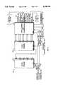
- FIG. 2is a block diagram of the clock repeater chip including a delay regulator circuit
- FIG. 3is a block diagram of a mode control logic circuit of the repeater chip including a truth table depicting the relationship between input and output signals of the mode control unit;
- FIG. 4is a diagram of a simple mode clock path of the repeater chip of FIG. 2;
- FIG. 5is a block diagram of a clock path control logic unit of the delay regulator
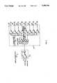
- FIG. 6is a block diagram of a clock delay path of the delay regulator.
- FIG. 7is a block diagram of a test register and a measurement latch of the clock delay path of the delay regulator in accordance with the invention.
- a synchronous computer system 10typically includes a central processing unit module 12, main memory modules 14a, 14b and an input/output unit module 16 interconnected by a high-speed, bidirectional synchronous bus 18.
- a clock module 15generates a system clock signal to synchronize the operations of the computer system.
- the system clock signalis globally-distributed via separate, generally radial, unidirectional clock lines 25 of the synchronous bus 18 to each module of the computer 10.
- a clock repeater chip 20 located on each modulereceives the distributed system clock signal as an input signal.
- the repeater chip 20is preferably a VLSI CMOS custom integrated circuit chip functionally configured to shape and amplify the input signal prior to generating multiple copies of it.
- the resulting output clock signalsare thereafter distributed to circuitry, e.g., bus interface circuitry 24, on each module.
- the chip 20converts controlled-edge, system clock signals with low-level voltages to a 0-5v, 50% duty cycle digital pulse required by the bus interface chips 24.
- clock signalsmay be "skew-regulated" by the repeater chip 20 by including additional delay regulation circuitry, as further described below.
- the clock signalsmay have phases different than the system clock signal.
- an embodiment of the present inventionmay support two clock channels. The second channel supports delay regulation and distribution of a second clock signal having the same frequency as the system clock signal, but locked in phase quadrature.
- FIG. 2is a block diagram of a clock repeater chip 20 including a delay regulator circuit.
- the system clock signal, PHO on line 25, and the second clock signal, PH90 on line 35are received at an input "buffer” stage 40, where they are processed, i.e., shaped and amplified.
- the processed clock signalsmay then be driven directly, i.e., "simple mode path” via line 26, to an output buffer stage 45 where they are regenerated into multiple copies for distribution to circuitry 24 on the module.
- the processed clock signalsmay be driven through a clock delay path 60 (FIG. 2) via a "process, voltage, temperature and loading (PVTL) mode path” 28 that is used to delay the signals prior to delivery to the output buffer stage 45.
- VTLprocess, voltage, temperature and loading
- a mode control logic unit 30Selection of simple or PVTL mode is determined by a mode control logic unit 30.
- a truth table of FIG. 3depicts the relationship between input and output signals of the unit 30. It will be understood to those skilled in the art that the table can be used to implement logic circuitry for the mode control unit 30.
- Simple modeallows the clock repeater chip 20 to operate at relatively low frequencies; this is advantageous when low speed, computer testing is performed.
- a LOOPIN signal on line 33 and a MODE signal on line 34are used to select the simple mode path of the output buffer stage 45 via a SIMPLEMODE signal on line 37; PVTL mode is selected via the PVTMODE signal on line 39.
- the LOOPIN pin 33which is shared between the mode control unit 30 and an input to the clock delay path 60, is used to enable a "test" of operation.
- the PH90 clock signal channel 35is not used; therefore its differential input pins, i.e., PH90 -- H on line 35a and PH90 L on line 35b, are used to select four sub-testing modes of operation.
- the PHO system clock signal on line 25is used to activate the logic circuitry used for each sub-mode.
- Overflow input signals, OVA on line 31 and OVB on line 32,are used in connection with an auto-ranging feature of the invention; this feature extends the frequency range of the clock repeater chip.
- a state machine clear signal SMCLR on line 38is used to clear sequential logic circuit of a clock path control unit 80 (FIG. 5), while a signal LOOPOUTEN on line 27a enables certain logic circuitry of a replica loop circuit 50.
- FIG. 4is a diagram of the simple mode path 26.
- the input buffer stage 40comprises differential and post-amplifier circuitry. Specifically, a differential amplifier 42 receives a low-level input signal, i.e., either square or limited-edge rate wave, and produces a "shaped", amplified square wave pulse having approximately the desired amplitude.
- the post-amplifier 44"cleans-up" the differential amplifier output signal; that is, it functions as a level-shifter to deliver a full amplitude signal to the output buffer stage 45.
- the post-amplifier 44also ensures the duty cycle of the signal is correct and in phase with the input signal PHO on line 25 (or PH90 on line 35).
- the output buffer stage 45comprises a predriver section 46 including AND and NAND gate circuitry, and an output driver section 48 including a plurality of tri-state drivers.
- the output buffer section 45is divided into two segments to accomodate the simple mode 26 and the PVTL mode 28 paths. For purposes of clarity, only the simple mode segment is shown.
- the predrivers 46are enabled by the SIMPLEMODE signal on line 37 generated by the mode control logic unit 30.
- the predrivers 37in turn, generate multiple copies of the processed input signal, while the output drivers 48 distribute these signals to circuitry on the module.
- the PVTL mode path 28enables measurement and delay compensation for the processed input signal.
- An absolute delay regulator circuitoperates in a cyclical fashion by periodically measuring the intrinsic delay of a clock path, including the PVTL clock delay path 60, on the chip 20. After a measurement, one of two delay adjusting units within the clock delay path 60 is updated, while the other delay unit determines the actual delay of the chip 20 from a previous measurement cycle. Specifically, the regulator updates a delay unit by adding a controlled amount of delay to the processed clock signal propagating through a delay line so that the output clock signal maintains a fixed-phase relationship with the input signal.
- the PVTL clock delay path 60 on the repeater chip 20includes the logic circuitry required to measure and compensate for the intrinic delay of the chip.
- a "replica loop" circuit 50simulates the logic and associated propagation delay of the clock path, as described further herein.
- An external loading network 55coupled between LOOPIN on line 33 and LOOPOUT on line 27, simulates the loading of printed circuit board etch traces connected to the outputs of chip 20, leading to external loads.
- a pulse generator 90supplies a precise measurement pulse needed to operate the clock delay path 60 and replica loop 50, while a clock path control logic unit 80 provides the necessary timing signals to perform delay regulation on the chip 20.
- FIG. 5is a block diagram of the clock path control logic unit 80, which preferably comprises registers and combinational logic configured to produce a sequential logic circuit, e.g., a "state machine" .
- the state machinecomprises two cascaded, 5-bit Johnson counters 84a, 84b coupled to a decoder and synchronizer unit 86.
- the state machineherein also referred to at 80, controls the sequencing of operations during a PVTL delay regulation cycle by generating timing signals used in the operation of the PVTL clock delay path 60. Specifically, a cycle of operation is as follows:
- State 2Write measurement word (stored in measurement latch) after decoding into A delay control register. The tap on clock A delay line is set to reflect the recent measurement. Clock B delay line (one for each clock phase) still controls clock delay;
- State 4Generate measurement pulse, freeze result in measurement latch and toggle clock delay control register selection via AB SELECT to select A delay control register (and clock A delay line) for delaying clock;
- the clock delay path 60is preferably one hundred and forty-four bits wide and generally includes a measurement circuit 62 and a pair, i.e., A and B, of delay adjusting units 64a, 64b, generally designated 64.
- a measurement signalpropagates through the replica loop 50 and into a tapped measurement delay line 65 where an "absolute" measurement of the chip intrinsic propagation delay is performed.
- the tapped delay line 65preferably comprises a string of inverters. To maintain correct polarity from the delay line, the taps are placed at the outputs of inverter-pairs. The delay resolution of the system is thus an inverter pair, which is a unit of measurement granularity.
- each delay unit 64includes a clock delay line and a tap select multiplexer.
- the clock delay lines 72a, 72b, generally designated 72,receive a processed clock signal on line 28 from the input buffer stage 40.
- double-bufferingallows the regulator to adjust the clock signal in one of the units by adding the desired delay, while the other unit still compensates for the previously-measured intrinic delay of chip. This technique contributes, in part, to a noninterrupted output clock signal.
- each delay control register 68enables respective A and B tap select multiplexers 74a, 74b, generally designated 74, to select an appropriate tap from its associated clock delay line 72.
- the A and B delay lines 72preferably comprise a string of inverters having taps at inverter-pair outputs.
- the delay lines 65 and 72employ two hundred and eighty-eight inverters or one hundred and forty-four inverter-pairs 70 with one hundred and forty-four taps 67 and 75a, 75b, respectively.
- a selected tapinserts a desired amount of delay to the processed input clock signal.
- Each tap multiplexer 74has an input for every tap in the delay line 72 and one output.
- the multiplexer 74is preferably implemented as an array of gates in a generally conventional "OR tree" configuration.
- the multiplexer 74selects one of the one hundred and forty-four taps 75 from the clock delay line 72, which, in turn, inserts the proper amount of delay to the processed clock signal on line 28 driven into the clock delay lines.
- the resulting A and B clock signals, A -- CLK on line 76a and B -- CLK on line 76b, from the multiplexers 74are thereafter coupled to a two-to-one clock delay multiplexer 77 that is enabled by clock synchronization logic 78.
- one of the clock signalsis selected and forwarded via a delay-regulated clock path 29 to the output buffer stage 45 for distribution to circuitry 24 on the module. Thereafter, the roles of the A and B delay adjusting units are switched.
- a test register 61allows for complete functional testing of the PVTL clock delay path 60 of the delay regulator.
- the test register 61which is coupled to the measurement and decode latch 66 in a "logical OR" configuration with respect to the measurement delay line 65, provides a means by which test patterns may be inserted into the repeater chip 20 during a test mode to fully exercise the entire clock delay path of the delay regulator.
- FIG. 7is a block diagram of the test register 61 and measurement latch 66.
- the D-input of the first device 240ais tied to a hardwired logical "1", e.g., V DD ; thereafter, the Q-outputs of the devices, generally designated 240, are tied to the D-inputs of adjacent devices 240 in a cascaded manner.
- the Q-output of the last device 240nis coupled to the input of a tri-state driver 245 that is enabled by a signal TESTLPOUTEN on line 232 from the mode control logic unit 30 (FIG. 3).
- the D-type devices 240are clocked by a TC signal on line 88 from the mode control logic unit 30, while a CLRTSR signal on line 87a from the clock path control logic 80 is tied to the clear input of each device.
- each device 240 of the test register 61is also coupled to a set input of a corresponding bit of the measurement latch 66.
- the D-input of each bit location, generally designated 260, of the latch 66is connected to a corresponding tap of the measurement delay line 65, while each NQ-output is coupled to the internal decoder circuit of the measurement latch 66.
- Each bit location 260is clocked by the measurement pulse emanating from the measurement pulse generator 90.
- the clear input of each location 260is coupled to a CLRMEAS signal on line 81 from the clock path control logic 80.
- FIGS. 3 and 5depict the input signals and control logic used to generate the timing signals.
- the MODE and LOOPIN signals on lines 34 and 33are used to place the repeater chip 20 in a test mode. Specifically, test mode is entered by placing non-asserted signals on both the MODE line 34 and LOOPIN line 33 of the chip. This deactivates the measurement delay line 65 by decoupling the replica loop 50 from the clock path, thus forcing a sequence of logic "0" bits into the delay line 65.
- the second phase clock signal PH 90 channelis not used during testing; therefore, its differential input pins, 90 -- H and 90 -- L, are used to select four sub-testing modes.
- the various combinations of differential input pins used to enter the four modesare as shown below, with a "0" indicating a non-asserted signal and a "1" indicating an asserted signal:
- the tri-state modeeffectively disables the output lines of the repeater chip 20 by placing its output drivers 48 of the output buffer stage 45 (FIG. 4) in high-impedance state; this is accomplished by deasserting SIMPLEMODE on line 37 and PVTMODE on line 39 (FIG. 3).
- Tri-state modeis used during manufacture testing of circuitry other than the repeater chip 20 on the module.
- the reset state machine modeis used to place the clock path logic state machine 80 in a known state, i.e., state 0 of the delay regulation cycle.
- the test register shift modeloads a selected pattern of logic "1" bits into the test register using the TC signal on line 88 to clock the test register flip-flop devices 240 and advance the loaded bits throughout the register 61.
- the measurement test modethen initiates a "test” measurement cycle by loading the selected test pattern from the test register 61 into the measurement latch 66.
- control logic state machine 80is inhibited from clearing the test register 61 with the CLRTSR signal on line 87a in test mode; it then clears the measurement latch 66 using the CLRMEAS signal on line 81 (see states 8 and 0 of delay regulation cycle).
- the "1's-only" bit test patternis then shifted into the test register 61 using the TC signal on line 88.
- a corresponding bit in the measurement latch 66is also set. This simulates the results of a measurement cycle with the test register contents stored in the measurement latch 66.
- the repeater chip 20is placed into a measurement test mode. Since the measurement line 65 is fully loaded with logic "0" bits, the contents of the test register 61 override the output of the measurement delay line 65. In a preferred embodiment of the invention, a minimum of one hundred PH 0 clock cycles are needed to ensure that a measurement test cycle operation has selected the clock delay paths of the A and B delay adjusting units 64a and 64b at least once. A clock output on line 22 of the chip 20 is then sampled; if a clock signal is present, then that column in the clock delay path is considered to be functional.
- test pattern corresponding to an incremental amount of delayis loaded into the test register 61 and the measurement test cycle is executed. This procedure is repeated until a test pattern corresponding to the maximum delay provided by the delay line 65 is loaded, the measurement test cycle executed and the output signal on line 22 sampled to indicate a fully functional chip. At this point, all columns, i.e., bit-slices, of the clock delay path have been individually exercised.
- each possible combination of the 144-bit registercan be selected as a test pattern to fully exercise each column, i.e., bit-slice, of the PVTL data path, including all clock delay taps of the delay lines.
- the logic of each bit-slice of the data pathmust be functional in order to produce a signal at the chip output pins. Therefore, a fault in the data path logic is manifested by the lack of an output signal for a particular test pattern.
- test modeis exited by asserting the LOOPIN signal.
Landscapes
- Physics & Mathematics (AREA)
- Engineering & Computer Science (AREA)
- General Engineering & Computer Science (AREA)
- General Physics & Mathematics (AREA)
- Theoretical Computer Science (AREA)
- Nonlinear Science (AREA)
- Tests Of Electronic Circuits (AREA)
- Test And Diagnosis Of Digital Computers (AREA)
Abstract
Description
TABLE 1 ______________________________________ TEST TRUTH TABLE MODE 90.sub.-- H 90.sub.-- L ______________________________________ Tri-state 0 0Reset State Machine 1 0Measurement Test 0 1Test Register Shift 1 1 ______________________________________
Claims (11)
Priority Applications (4)
| Application Number | Priority Date | Filing Date | Title |
|---|---|---|---|
| US07/764,314US5198758A (en) | 1991-09-23 | 1991-09-23 | Method and apparatus for complete functional testing of a complex signal path of a semiconductor chip |
| PCT/US1992/008079WO1993006657A1 (en) | 1991-09-23 | 1992-09-23 | Update synchronizer |
| PCT/US1992/008086WO1993006544A1 (en) | 1991-09-23 | 1992-09-23 | Method and apparatus for clock skew reduction through absolute delay regulation |
| PCT/US1992/008087WO1993006497A1 (en) | 1991-09-23 | 1992-09-23 | Method and apparatus for complete functional testing of a complex signal path of a semiconductor chip |
Applications Claiming Priority (1)
| Application Number | Priority Date | Filing Date | Title |
|---|---|---|---|
| US07/764,314US5198758A (en) | 1991-09-23 | 1991-09-23 | Method and apparatus for complete functional testing of a complex signal path of a semiconductor chip |
Publications (1)
| Publication Number | Publication Date |
|---|---|
| US5198758Atrue US5198758A (en) | 1993-03-30 |
Family
ID=25070347
Family Applications (1)
| Application Number | Title | Priority Date | Filing Date |
|---|---|---|---|
| US07/764,314Expired - LifetimeUS5198758A (en) | 1991-09-23 | 1991-09-23 | Method and apparatus for complete functional testing of a complex signal path of a semiconductor chip |
Country Status (1)
| Country | Link |
|---|---|
| US (1) | US5198758A (en) |
Cited By (46)
| Publication number | Priority date | Publication date | Assignee | Title |
|---|---|---|---|---|
| US5337254A (en)* | 1991-12-16 | 1994-08-09 | Hewlett-Packard Company | Programmable integrated circuit output pad |
| US5369640A (en)* | 1993-04-16 | 1994-11-29 | Digital Equipment Corporation | Method and apparatus for clock skew reduction through remote delay regulation |
| US5406567A (en)* | 1992-06-12 | 1995-04-11 | Nec Corporation | Off-line test circuit of a semiconnector integrated logic circuit |
| US5434805A (en)* | 1991-09-12 | 1995-07-18 | Mitsubishi Denki Kabushiki Kaisha | Test timing program automatic generator |
| US5471482A (en)* | 1994-04-05 | 1995-11-28 | Unisys Corporation | VLSI embedded RAM test |
| US5511164A (en) | 1995-03-01 | 1996-04-23 | Unisys Corporation | Method and apparatus for determining the source and nature of an error within a computer system |
| US5659255A (en)* | 1995-04-14 | 1997-08-19 | Cascade Microtech, Inc. | Method of evaluating signal conditions in a probe measurement network having a plurality of separate measurement channels |
| US5778251A (en)* | 1994-09-20 | 1998-07-07 | Fujitsu Limited | State machine in which subsequent state can be directly inputted externally and transition can be stopped retaining the current state |
| US5883844A (en)* | 1997-05-23 | 1999-03-16 | Stmicroelectronics, Inc. | Method of stress testing integrated circuit having memory and integrated circuit having stress tester for memory thereof |
| US6119253A (en)* | 1996-10-18 | 2000-09-12 | Samsung Electronics, Co., Ltd. | Method and device for setting a plurality of test modes using external pins |
| US20020144203A1 (en)* | 2001-03-28 | 2002-10-03 | Ko-Yan Shih | Method and circuit for testing a chip |
| US6657451B2 (en)* | 1999-11-29 | 2003-12-02 | Koninklijke Philips Electronics N.V. | Method and integrated circuit arranged for feeding a test forcing pattern on a single shared pin of the circuit |
| US6728911B1 (en) | 2000-11-16 | 2004-04-27 | Utstarcom, Inc. | System and method for testing memory systems |
| US20040130366A1 (en)* | 2003-01-08 | 2004-07-08 | Feng Lin | Method and system for delay control in synchronization circuits |
| US20040150416A1 (en)* | 1999-06-30 | 2004-08-05 | Cowan Clarence E. | Probe station thermal chuck with shielding for capacitive current |
| US20040158757A1 (en)* | 2000-08-31 | 2004-08-12 | Feng Lin | Interleaved delay line for phase locked and delay locked loops |
| US20040222807A1 (en)* | 2003-05-06 | 2004-11-11 | John Dunklee | Switched suspended conductor and connection |
| US20050007581A1 (en)* | 2001-08-31 | 2005-01-13 | Harris Daniel L. | Optical testing device |
| US20050088191A1 (en)* | 2003-10-22 | 2005-04-28 | Lesher Timothy E. | Probe testing structure |
| US20050099192A1 (en)* | 2002-11-25 | 2005-05-12 | John Dunklee | Probe station with low inductance path |
| US20050140384A1 (en)* | 2003-12-24 | 2005-06-30 | Peter Andrews | Chuck with integrated wafer support |
| US20050216640A1 (en)* | 2000-09-22 | 2005-09-29 | Wolfram Drescher | Processor bus arrangement |
| US20050287685A1 (en)* | 2004-06-14 | 2005-12-29 | Mcfadden Bruce | Localizing a temperature of a device for testing |
| US20060060119A1 (en)* | 2004-09-17 | 2006-03-23 | South Boston Port Transfer, Llc | Marine vessel for processing solid waste; method for collecting, processing and shipping solid waste; and plant for processing solid waste |
| US20060190790A1 (en)* | 2005-02-22 | 2006-08-24 | Pilling David J | In-situ monitor of process and device parameters in integrated circuits |
| US7138810B2 (en) | 2002-11-08 | 2006-11-21 | Cascade Microtech, Inc. | Probe station with low noise characteristics |
| US7176705B2 (en) | 2004-06-07 | 2007-02-13 | Cascade Microtech, Inc. | Thermal optical chuck |
| US7190181B2 (en) | 1997-06-06 | 2007-03-13 | Cascade Microtech, Inc. | Probe station having multiple enclosures |
| US7221146B2 (en) | 2002-12-13 | 2007-05-22 | Cascade Microtech, Inc. | Guarded tub enclosure |
| US7330023B2 (en) | 1992-06-11 | 2008-02-12 | Cascade Microtech, Inc. | Wafer probe station having a skirting component |
| US7348787B2 (en) | 1992-06-11 | 2008-03-25 | Cascade Microtech, Inc. | Wafer probe station having environment control enclosure |
| US7352168B2 (en) | 2000-09-05 | 2008-04-01 | Cascade Microtech, Inc. | Chuck for holding a device under test |
| US7368925B2 (en) | 2002-01-25 | 2008-05-06 | Cascade Microtech, Inc. | Probe station with two platens |
| US20080157840A1 (en)* | 2006-12-31 | 2008-07-03 | Texas Instrument Incorporated | Systems and Methods for Adding a Delay to a Signal |
| US7492172B2 (en) | 2003-05-23 | 2009-02-17 | Cascade Microtech, Inc. | Chuck for holding a device under test |
| US7535247B2 (en) | 2005-01-31 | 2009-05-19 | Cascade Microtech, Inc. | Interface for testing semiconductors |
| US7554322B2 (en) | 2000-09-05 | 2009-06-30 | Cascade Microtech, Inc. | Probe station |
| US7594149B2 (en)* | 2005-02-22 | 2009-09-22 | Integrated Device Technology, Inc. | In-situ monitor of process and device parameters in integrated circuits |
| US7656172B2 (en) | 2005-01-31 | 2010-02-02 | Cascade Microtech, Inc. | System for testing semiconductors |
| US20100127714A1 (en)* | 2008-11-24 | 2010-05-27 | Cascade Microtech, Inc. | Test system for flicker noise |
| US8624680B2 (en) | 2004-11-04 | 2014-01-07 | Steven T. Stoiber | Ring based impedance control of an output driver |
| US8952713B1 (en)* | 2012-02-08 | 2015-02-10 | Altera Corporation | Method and apparatus for die testing |
| US20170242409A1 (en)* | 2016-02-19 | 2017-08-24 | Dspace Digital Signal Processing And Control Engineering Gmbh | Method for configuring a test device set up for testing an electronic control unit |
| CN110275805A (en)* | 2019-06-13 | 2019-09-24 | 上海琪埔维半导体有限公司 | A kind of full-automatic test system for MCU chip |
| CN113740718A (en)* | 2020-05-29 | 2021-12-03 | 深圳市中兴微电子技术有限公司 | Method and circuit for measuring time sequence unit establishing time |
| CN114138582A (en)* | 2021-12-08 | 2022-03-04 | 中科亿海微电子科技(苏州)有限公司 | System and method for measuring decoding penetration delay of financial accelerator card based on FPGA |
Citations (4)
| Publication number | Priority date | Publication date | Assignee | Title |
|---|---|---|---|---|
| US4703257A (en)* | 1984-12-24 | 1987-10-27 | Hitachi, Ltd. | Logic circuit having a test data scan circuit |
| US4782283A (en)* | 1986-08-22 | 1988-11-01 | Aida Corporation | Apparatus for scan testing CMOS integrated systems |
| US4931722A (en)* | 1985-11-07 | 1990-06-05 | Control Data Corporation | Flexible imbedded test system for VLSI circuits |
| US5003256A (en)* | 1989-09-07 | 1991-03-26 | Amdahl Corporation | Clock skew measurement technique |
- 1991
- 1991-09-23USUS07/764,314patent/US5198758A/ennot_activeExpired - Lifetime
Patent Citations (4)
| Publication number | Priority date | Publication date | Assignee | Title |
|---|---|---|---|---|
| US4703257A (en)* | 1984-12-24 | 1987-10-27 | Hitachi, Ltd. | Logic circuit having a test data scan circuit |
| US4931722A (en)* | 1985-11-07 | 1990-06-05 | Control Data Corporation | Flexible imbedded test system for VLSI circuits |
| US4782283A (en)* | 1986-08-22 | 1988-11-01 | Aida Corporation | Apparatus for scan testing CMOS integrated systems |
| US5003256A (en)* | 1989-09-07 | 1991-03-26 | Amdahl Corporation | Clock skew measurement technique |
Cited By (94)
| Publication number | Priority date | Publication date | Assignee | Title |
|---|---|---|---|---|
| US5434805A (en)* | 1991-09-12 | 1995-07-18 | Mitsubishi Denki Kabushiki Kaisha | Test timing program automatic generator |
| US5337254A (en)* | 1991-12-16 | 1994-08-09 | Hewlett-Packard Company | Programmable integrated circuit output pad |
| US7595632B2 (en) | 1992-06-11 | 2009-09-29 | Cascade Microtech, Inc. | Wafer probe station having environment control enclosure |
| US7330023B2 (en) | 1992-06-11 | 2008-02-12 | Cascade Microtech, Inc. | Wafer probe station having a skirting component |
| US7348787B2 (en) | 1992-06-11 | 2008-03-25 | Cascade Microtech, Inc. | Wafer probe station having environment control enclosure |
| US7492147B2 (en) | 1992-06-11 | 2009-02-17 | Cascade Microtech, Inc. | Wafer probe station having a skirting component |
| US7589518B2 (en) | 1992-06-11 | 2009-09-15 | Cascade Microtech, Inc. | Wafer probe station having a skirting component |
| US5406567A (en)* | 1992-06-12 | 1995-04-11 | Nec Corporation | Off-line test circuit of a semiconnector integrated logic circuit |
| US5369640A (en)* | 1993-04-16 | 1994-11-29 | Digital Equipment Corporation | Method and apparatus for clock skew reduction through remote delay regulation |
| US5471482A (en)* | 1994-04-05 | 1995-11-28 | Unisys Corporation | VLSI embedded RAM test |
| US5778251A (en)* | 1994-09-20 | 1998-07-07 | Fujitsu Limited | State machine in which subsequent state can be directly inputted externally and transition can be stopped retaining the current state |
| US6202102B1 (en) | 1994-09-20 | 2001-03-13 | Fujitsu Limited | State machine and communication terminal |
| US5983287A (en)* | 1994-09-20 | 1999-11-09 | Fujitsu Limited | Communication terminal having a state machine for automatically starting subsequent control in response to a lock detection signal provided by a PLL (phase lock loop) |
| US5511164A (en) | 1995-03-01 | 1996-04-23 | Unisys Corporation | Method and apparatus for determining the source and nature of an error within a computer system |
| US20060103403A1 (en)* | 1995-04-14 | 2006-05-18 | Cascade Microtech, Inc. | System for evaluating probing networks |
| US7164279B2 (en) | 1995-04-14 | 2007-01-16 | Cascade Microtech, Inc. | System for evaluating probing networks |
| US7321233B2 (en) | 1995-04-14 | 2008-01-22 | Cascade Microtech, Inc. | System for evaluating probing networks |
| US5659255A (en)* | 1995-04-14 | 1997-08-19 | Cascade Microtech, Inc. | Method of evaluating signal conditions in a probe measurement network having a plurality of separate measurement channels |
| US6119253A (en)* | 1996-10-18 | 2000-09-12 | Samsung Electronics, Co., Ltd. | Method and device for setting a plurality of test modes using external pins |
| US5883844A (en)* | 1997-05-23 | 1999-03-16 | Stmicroelectronics, Inc. | Method of stress testing integrated circuit having memory and integrated circuit having stress tester for memory thereof |
| US7436170B2 (en) | 1997-06-06 | 2008-10-14 | Cascade Microtech, Inc. | Probe station having multiple enclosures |
| US7190181B2 (en) | 1997-06-06 | 2007-03-13 | Cascade Microtech, Inc. | Probe station having multiple enclosures |
| US7626379B2 (en) | 1997-06-06 | 2009-12-01 | Cascade Microtech, Inc. | Probe station having multiple enclosures |
| US20040150416A1 (en)* | 1999-06-30 | 2004-08-05 | Cowan Clarence E. | Probe station thermal chuck with shielding for capacitive current |
| US7616017B2 (en) | 1999-06-30 | 2009-11-10 | Cascade Microtech, Inc. | Probe station thermal chuck with shielding for capacitive current |
| US7292057B2 (en) | 1999-06-30 | 2007-11-06 | Cascade Microtech, Inc. | Probe station thermal chuck with shielding for capacitive current |
| US20070030021A1 (en)* | 1999-06-30 | 2007-02-08 | Cascade Microtech Inc. | Probe station thermal chuck with shielding for capacitive current |
| US7138813B2 (en) | 1999-06-30 | 2006-11-21 | Cascade Microtech, Inc. | Probe station thermal chuck with shielding for capacitive current |
| US6657451B2 (en)* | 1999-11-29 | 2003-12-02 | Koninklijke Philips Electronics N.V. | Method and integrated circuit arranged for feeding a test forcing pattern on a single shared pin of the circuit |
| US6868504B1 (en)* | 2000-08-31 | 2005-03-15 | Micron Technology, Inc. | Interleaved delay line for phase locked and delay locked loops |
| US20040158757A1 (en)* | 2000-08-31 | 2004-08-12 | Feng Lin | Interleaved delay line for phase locked and delay locked loops |
| US6845459B2 (en) | 2000-08-31 | 2005-01-18 | Micron Technology, Inc. | System and method to provide tight locking for DLL and PLL with large range, and dynamic tracking of PVT variations using interleaved delay lines |
| US6845458B2 (en) | 2000-08-31 | 2005-01-18 | Micron Technology, Inc. | System and method of operation of DLL and PLL to provide tight locking with large range, and dynamic tracking of PVT variations using interleaved delay lines |
| US7501810B2 (en) | 2000-09-05 | 2009-03-10 | Cascade Microtech, Inc. | Chuck for holding a device under test |
| US7423419B2 (en) | 2000-09-05 | 2008-09-09 | Cascade Microtech, Inc. | Chuck for holding a device under test |
| US7352168B2 (en) | 2000-09-05 | 2008-04-01 | Cascade Microtech, Inc. | Chuck for holding a device under test |
| US7969173B2 (en) | 2000-09-05 | 2011-06-28 | Cascade Microtech, Inc. | Chuck for holding a device under test |
| US7514915B2 (en) | 2000-09-05 | 2009-04-07 | Cascade Microtech, Inc. | Chuck for holding a device under test |
| US7688062B2 (en) | 2000-09-05 | 2010-03-30 | Cascade Microtech, Inc. | Probe station |
| US7554322B2 (en) | 2000-09-05 | 2009-06-30 | Cascade Microtech, Inc. | Probe station |
| US7518358B2 (en) | 2000-09-05 | 2009-04-14 | Cascade Microtech, Inc. | Chuck for holding a device under test |
| US7647445B2 (en)* | 2000-09-22 | 2010-01-12 | Nxp B.V. | Processor bus arrangement |
| US20050216640A1 (en)* | 2000-09-22 | 2005-09-29 | Wolfram Drescher | Processor bus arrangement |
| US6728911B1 (en) | 2000-11-16 | 2004-04-27 | Utstarcom, Inc. | System and method for testing memory systems |
| US20020144203A1 (en)* | 2001-03-28 | 2002-10-03 | Ko-Yan Shih | Method and circuit for testing a chip |
| US7089472B2 (en)* | 2001-03-28 | 2006-08-08 | Via Technologies, Inc. | Method and circuit for testing a chip |
| US7268533B2 (en) | 2001-08-31 | 2007-09-11 | Cascade Microtech, Inc. | Optical testing device |
| US20050007581A1 (en)* | 2001-08-31 | 2005-01-13 | Harris Daniel L. | Optical testing device |
| US7368925B2 (en) | 2002-01-25 | 2008-05-06 | Cascade Microtech, Inc. | Probe station with two platens |
| US7295025B2 (en) | 2002-11-08 | 2007-11-13 | Cascade Microtech, Inc. | Probe station with low noise characteristics |
| US7138810B2 (en) | 2002-11-08 | 2006-11-21 | Cascade Microtech, Inc. | Probe station with low noise characteristics |
| US7550984B2 (en) | 2002-11-08 | 2009-06-23 | Cascade Microtech, Inc. | Probe station with low noise characteristics |
| US7498828B2 (en) | 2002-11-25 | 2009-03-03 | Cascade Microtech, Inc. | Probe station with low inductance path |
| US7250779B2 (en) | 2002-11-25 | 2007-07-31 | Cascade Microtech, Inc. | Probe station with low inductance path |
| US20050099192A1 (en)* | 2002-11-25 | 2005-05-12 | John Dunklee | Probe station with low inductance path |
| US7221146B2 (en) | 2002-12-13 | 2007-05-22 | Cascade Microtech, Inc. | Guarded tub enclosure |
| US7639003B2 (en) | 2002-12-13 | 2009-12-29 | Cascade Microtech, Inc. | Guarded tub enclosure |
| US6836166B2 (en) | 2003-01-08 | 2004-12-28 | Micron Technology, Inc. | Method and system for delay control in synchronization circuits |
| US20040130366A1 (en)* | 2003-01-08 | 2004-07-08 | Feng Lin | Method and system for delay control in synchronization circuits |
| US7468609B2 (en) | 2003-05-06 | 2008-12-23 | Cascade Microtech, Inc. | Switched suspended conductor and connection |
| US20040222807A1 (en)* | 2003-05-06 | 2004-11-11 | John Dunklee | Switched suspended conductor and connection |
| US7221172B2 (en) | 2003-05-06 | 2007-05-22 | Cascade Microtech, Inc. | Switched suspended conductor and connection |
| US7876115B2 (en) | 2003-05-23 | 2011-01-25 | Cascade Microtech, Inc. | Chuck for holding a device under test |
| US7492172B2 (en) | 2003-05-23 | 2009-02-17 | Cascade Microtech, Inc. | Chuck for holding a device under test |
| US7250626B2 (en) | 2003-10-22 | 2007-07-31 | Cascade Microtech, Inc. | Probe testing structure |
| US8069491B2 (en) | 2003-10-22 | 2011-11-29 | Cascade Microtech, Inc. | Probe testing structure |
| US20050088191A1 (en)* | 2003-10-22 | 2005-04-28 | Lesher Timothy E. | Probe testing structure |
| US7688091B2 (en) | 2003-12-24 | 2010-03-30 | Cascade Microtech, Inc. | Chuck with integrated wafer support |
| US7362115B2 (en) | 2003-12-24 | 2008-04-22 | Cascade Microtech, Inc. | Chuck with integrated wafer support |
| US7187188B2 (en) | 2003-12-24 | 2007-03-06 | Cascade Microtech, Inc. | Chuck with integrated wafer support |
| US20050140384A1 (en)* | 2003-12-24 | 2005-06-30 | Peter Andrews | Chuck with integrated wafer support |
| US7176705B2 (en) | 2004-06-07 | 2007-02-13 | Cascade Microtech, Inc. | Thermal optical chuck |
| US7504823B2 (en) | 2004-06-07 | 2009-03-17 | Cascade Microtech, Inc. | Thermal optical chuck |
| US7330041B2 (en) | 2004-06-14 | 2008-02-12 | Cascade Microtech, Inc. | Localizing a temperature of a device for testing |
| US20050287685A1 (en)* | 2004-06-14 | 2005-12-29 | Mcfadden Bruce | Localizing a temperature of a device for testing |
| US20060060119A1 (en)* | 2004-09-17 | 2006-03-23 | South Boston Port Transfer, Llc | Marine vessel for processing solid waste; method for collecting, processing and shipping solid waste; and plant for processing solid waste |
| US8624680B2 (en) | 2004-11-04 | 2014-01-07 | Steven T. Stoiber | Ring based impedance control of an output driver |
| US7535247B2 (en) | 2005-01-31 | 2009-05-19 | Cascade Microtech, Inc. | Interface for testing semiconductors |
| US7656172B2 (en) | 2005-01-31 | 2010-02-02 | Cascade Microtech, Inc. | System for testing semiconductors |
| US7898281B2 (en) | 2005-01-31 | 2011-03-01 | Cascade Mircotech, Inc. | Interface for testing semiconductors |
| US7940069B2 (en) | 2005-01-31 | 2011-05-10 | Cascade Microtech, Inc. | System for testing semiconductors |
| US7594149B2 (en)* | 2005-02-22 | 2009-09-22 | Integrated Device Technology, Inc. | In-situ monitor of process and device parameters in integrated circuits |
| US20060190790A1 (en)* | 2005-02-22 | 2006-08-24 | Pilling David J | In-situ monitor of process and device parameters in integrated circuits |
| US7583087B2 (en)* | 2005-02-22 | 2009-09-01 | Integrated Device Technology, Inc. | In-situ monitor of process and device parameters in integrated circuits |
| US7814450B2 (en)* | 2006-12-31 | 2010-10-12 | Texas Instruments Incorporated | Active skew control of a digital phase-lock loop using delay lock-loops |
| US20080157840A1 (en)* | 2006-12-31 | 2008-07-03 | Texas Instrument Incorporated | Systems and Methods for Adding a Delay to a Signal |
| US8319503B2 (en) | 2008-11-24 | 2012-11-27 | Cascade Microtech, Inc. | Test apparatus for measuring a characteristic of a device under test |
| US20100127714A1 (en)* | 2008-11-24 | 2010-05-27 | Cascade Microtech, Inc. | Test system for flicker noise |
| US8952713B1 (en)* | 2012-02-08 | 2015-02-10 | Altera Corporation | Method and apparatus for die testing |
| US20170242409A1 (en)* | 2016-02-19 | 2017-08-24 | Dspace Digital Signal Processing And Control Engineering Gmbh | Method for configuring a test device set up for testing an electronic control unit |
| US10095194B2 (en)* | 2016-02-19 | 2018-10-09 | Dspace Digital Signal Processing And Control Engineering Gmbh | Method for configuring a test device set up for testing an electronic control unit |
| CN110275805A (en)* | 2019-06-13 | 2019-09-24 | 上海琪埔维半导体有限公司 | A kind of full-automatic test system for MCU chip |
| CN113740718A (en)* | 2020-05-29 | 2021-12-03 | 深圳市中兴微电子技术有限公司 | Method and circuit for measuring time sequence unit establishing time |
| CN114138582A (en)* | 2021-12-08 | 2022-03-04 | 中科亿海微电子科技(苏州)有限公司 | System and method for measuring decoding penetration delay of financial accelerator card based on FPGA |
Similar Documents
| Publication | Publication Date | Title |
|---|---|---|
| US5198758A (en) | Method and apparatus for complete functional testing of a complex signal path of a semiconductor chip | |
| US5272390A (en) | Method and apparatus for clock skew reduction through absolute delay regulation | |
| US6763489B2 (en) | Method for scan testing of digital circuit, digital circuit for use therewith and program product for incorporating test methodology into circuit description | |
| US6243841B1 (en) | Automated test and evaluation sampling system and method | |
| US6320436B1 (en) | Clock skew removal apparatus | |
| US8775857B2 (en) | Sequential on-chip clock controller with dynamic bypass for multi-clock domain testing | |
| US6065126A (en) | Method and apparatus for executing plurality of operations per clock cycle in a single processing unit with a self-timed and self-enabled distributed clock | |
| EP1851560B1 (en) | Testing of an integrated circuit with a plurality of clock domains | |
| KR20090126295A (en) | Circuit to Avoid Peak Power Problems During Scan Shift | |
| KR20010033037A (en) | Method and apparatus for utilizing mux scan flip-flops to test speed related defects | |
| US4961013A (en) | Apparatus for generation of scan control signals for initialization and diagnosis of circuitry in a computer | |
| US10999050B1 (en) | Methods and apparatus for data synchronization in systems having multiple clock and reset domains | |
| US20060117230A1 (en) | System and method for testing integrated circuits at operational speed using high-frequency clock converter | |
| US5705942A (en) | Method and apparatus for locating and improving critical speed paths in VLSI integrated circuits | |
| EP3859361B1 (en) | An electronic circuit and corresponding method of testing electronic circuits | |
| US10276258B2 (en) | Memory controller for selecting read clock signal | |
| US20140140159A1 (en) | Short asynchronous glitch | |
| US12095459B2 (en) | Anti-aging clock source multiplexing | |
| WO1993006497A1 (en) | Method and apparatus for complete functional testing of a complex signal path of a semiconductor chip | |
| US6748563B1 (en) | Method and apparatus for testing path delays in a high-speed boundary scan implementation | |
| US7221126B1 (en) | Apparatus and method to align clocks for repeatable system testing | |
| US7421634B2 (en) | Sequential scan based techniques to test interface between modules designed to operate at different frequencies | |
| US5867694A (en) | Information handling system including apparatus and method for controlling clock signals operating at different frequencies | |
| Semba et al. | A study on the design of interface circuits between synchronous-asynchronous modules using click elements | |
| US8090929B2 (en) | Generating clock signals for coupled ASIC chips in processor interface with X and Y logic operable in functional and scanning modes |
Legal Events
| Date | Code | Title | Description |
|---|---|---|---|
| AS | Assignment | Owner name:DIGITAL EQUIPMENT CORPORTION, MASSACHUSETTS Free format text:ASSIGNMENT OF ASSIGNORS INTEREST.;ASSIGNORS:IKNAIAN, RUSSELL;WATSON, RICHARD B. JR.;REEL/FRAME:005885/0170 Effective date:19910923 | |
| STCF | Information on status: patent grant | Free format text:PATENTED CASE | |
| FEPP | Fee payment procedure | Free format text:PAYOR NUMBER ASSIGNED (ORIGINAL EVENT CODE: ASPN); ENTITY STATUS OF PATENT OWNER: LARGE ENTITY | |
| FPAY | Fee payment | Year of fee payment:4 | |
| FPAY | Fee payment | Year of fee payment:8 | |
| AS | Assignment | Owner name:COMPAQ INFORMATION TECHNOLOGIES GROUP, L.P., TEXAS Free format text:ASSIGNMENT OF ASSIGNORS INTEREST;ASSIGNORS:DIGITAL EQUIPMENT CORPORATION;COMPAQ COMPUTER CORPORATION;REEL/FRAME:012447/0903;SIGNING DATES FROM 19991209 TO 20010620 | |
| AS | Assignment | Owner name:HEWLETT-PACKARD DEVELOPMENT COMPANY, L.P., TEXAS Free format text:CHANGE OF NAME;ASSIGNOR:COMPAQ INFORMATION TECHNOLOGIES GROUP, LP;REEL/FRAME:015000/0305 Effective date:20021001 | |
| FPAY | Fee payment | Year of fee payment:12 |