US5198702A - Control and safety system for electrically operated devices - Google Patents
Control and safety system for electrically operated devicesDownload PDFInfo
- Publication number
- US5198702A US5198702AUS07/657,208US65720891AUS5198702AUS 5198702 AUS5198702 AUS 5198702AUS 65720891 AUS65720891 AUS 65720891AUS 5198702 AUS5198702 AUS 5198702A
- Authority
- US
- United States
- Prior art keywords
- operator
- circuit
- gloves
- box
- worn
- Prior art date
- Legal status (The legal status is an assumption and is not a legal conclusion. Google has not performed a legal analysis and makes no representation as to the accuracy of the status listed.)
- Expired - Fee Related
Links
- 239000013307optical fiberSubstances0.000claimsabstractdescription12
- 239000002184metalSubstances0.000claimsabstractdescription10
- 230000002441reversible effectEffects0.000claimsabstractdescription5
- 239000004020conductorSubstances0.000description2
- 235000013372meatNutrition0.000description2
- 230000002159abnormal effectEffects0.000description1
- 230000005856abnormalityEffects0.000description1
- 230000005494condensationEffects0.000description1
- 238000009833condensationMethods0.000description1
- 238000010276constructionMethods0.000description1
- 238000010586diagramMethods0.000description1
- 230000007257malfunctionEffects0.000description1
- 239000002985plastic filmSubstances0.000description1
- 230000035945sensitivityEffects0.000description1
- 238000011144upstream manufacturingMethods0.000description1
- XLYOFNOQVPJJNP-UHFFFAOYSA-NwaterSubstancesOXLYOFNOQVPJJNP-UHFFFAOYSA-N0.000description1
- 210000000707wristAnatomy0.000description1
Images


Classifications
- F—MECHANICAL ENGINEERING; LIGHTING; HEATING; WEAPONS; BLASTING
- F16—ENGINEERING ELEMENTS AND UNITS; GENERAL MEASURES FOR PRODUCING AND MAINTAINING EFFECTIVE FUNCTIONING OF MACHINES OR INSTALLATIONS; THERMAL INSULATION IN GENERAL
- F16P—SAFETY DEVICES IN GENERAL; SAFETY DEVICES FOR PRESSES
- F16P3/00—Safety devices acting in conjunction with the control or operation of a machine; Control arrangements requiring the simultaneous use of two or more parts of the body
- F16P3/12—Safety devices acting in conjunction with the control or operation of a machine; Control arrangements requiring the simultaneous use of two or more parts of the body with means, e.g. feelers, which in case of the presence of a body part of a person in or near the danger zone influence the control or operation of the machine
Definitions
- a control system for motor-operated power machineswhich ensures operator safety by instantaneously interrupting power to the motor driving the rotary tool, such as a blade, saw or the like, when an electrically conducting metal glove worn by the operator or his hand makes contact with the tool or other conducting part of the machine.
- the conducting metal gloveis covered with an insulating sheath, such as a glove plastic sheet glove, to prevent electrical connection being made via for example a bulk of meat handled by the operator.
- the operator's glove, or a conducting arm band worn by him,is electrically connected to a safety switch which instantaneously disconnects the power when the operator's glove or hand closes a circuit by touching a part of the machine.
- the control systemcomprises means for reversing the polarity of the electric motor, and further reduces the possibility of damage to the operator by, if appropriate, rotating the motor in the reverse direction through a fraction of a revolution.
- a manual switchhas to be operated to reset the configuration of the safety circuit to its state prior to intervention.
- Each metal gloveis connected to the safety switch by an electrode fixed to the operator's wrist in proximity to the glove, and the two electrodes have to be worn by the operator to make it possible to connect current to the motor for the rotating element.
- the aforesaid systemrequires the operator to wear two electorally conducting gloves, which are connected via electric wires provided with suitable plugs to corresponding sockets in the body of the power machine, such as a skinning machine.
- the plugs and socketsare of coaxial type in the sense that they comprise a pin plus a central receiving seat for connection to one wire, and a coaxial skirt external to the pin plus a receiving cavity for connection to the other wire.
- Said two wiresare connected to a safety circuit such as that shown in FIG. 6 of said U.S. Pat. No. 4,965,909 which is contained in the base of the machine and receives current from the general machine circuit shown in FIG. 5 of said European patent application.
- the electronic circuit which receives the signals from the electrically conducting glovesis powered, via a transformer, by the general machine circuit connected to the mains, with the result that abnormalities or malfunctions could arise, producing electrical discharges across the gloves, with imaginable consequences for the operator.
- the plug of the coaxial cable which connects the gloves to the machine structureis highly sensitive to moisture, and any occurring condensation can short-circuit the two poles of the cable, to enable the machine to run even when the operator is not wearing the gloves.
- the electronic safety circuitwhich generates the pulses and feeds them to the machine electric circuit to interrupt power to the motor, is powered by an independent 12 V. d.c. battery and is no longer located in the base of the machine but on the operator.
- said electronic circuitno longer serves both gloves, and instead an independent circuit is provided for each glove.
- said signals or pulses of the electronic safety circuitare transmitted to the machine electric circuit by an optical fibre.
- FIG. 1shows that part of the invention worn by the operator.
- FIG. 2is a perspective view of a skinning machine comprising the invention.
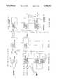
- FIG. 3shows the block diagram of the electrical and electronic part of the invention.
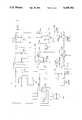
- FIG. 4is a detailed representation of the receiver and control unit housed in the machine.
- FIG. 5is a detailed representation of the sensor-transmitter unit located on the operator.
- the figuresshow a working coat 1 completed by two metal mesh gloves A and B, from each of which a conductor wire 2, 3 extends to a box 4 fixed in any convenient manner to the operator's body.
- the boxcontains a 12 V rechargeable battery 5 of about 2 Ah powering a circuit such as that of FIG. 5, from which there extends an optical fiber cable 12 and a conductor cable 7 connected both to earth and to the feed roller 8 which feeds the meat under the skinning blade 9 of the machine 10.
- the cables 12 and 7are connected to the skinning machine 10 (FIG. 2) which contains the circuit of FIG. 4.
- the machine 10upperly comprises a table 11 located upstream of a knurled roller 8, or motorized feed roller, downstream of and close to which there is the skinning blade 9.
- That part of the electronic circuit of the machine 10 comprising the safety device according to the present inventionis shown schematically as a block system in FIG. 3.
- the electronic circuit of the machine 10is connected by an optical fiber 12 or equivalent device to the electronic circuit which senses and transmits abnormal situations, this circuit being completely housed in the box 4 fixed to the operator's body. Said circuit is schematically illustrated in FIG. 3, again by a block system. Both of these circuits are shown in detail in FIGS. 4 and 5 respectively.
- FIG. 5will first be examined, although components indicated by totally normal symbols will not be described, the description being limited to that necessary for understanding operation.
- the 12 V battery 5powers via the DC/DC converter, two separate circuits in which the live poles are indicated by +12A and +12B, whereas the poles at zero voltage are indicated by the symbols 0A and 0B respectively.
- each of said circuitthere is connected a metal glove A and B respectively, these both being connected to earth via the cable 7.
- the block 120(FIG. 5) emits via the optical fiber 12 a light signal which when received by the block 121 (FIG. 4) enables normal machine operation.
- Both of these circuitsare connected to a memory circuit consisting of a flip-flop circuit indicated by the letters C on the schematic, so that any accidental contact between one or the other metal glove with the roller 8 or with one of the metal parts electrically connected to it modifies a usual electronic circuit contained in the block 120, which interrupts the light pulse through the optical fibre 12.
- the circuitAfter each interruption of the light signal the circuit is zeroed by a pushbutton indicated on the schematic as RESET and operated by the operator.
- the optical fiber 12is connected to the receiver block 121 forming part of the circuit contained in the machine base and illustrated in FIG. 4. No detailed description of this circuit is given as it is immediately understandable from the drawing. It is powered from the mains with 24 V alternating current via the poles 41 and 40, from which by means of a diode rectifier bridge and the illustrated circuit, two direct current voltages are made available, namely 12 V and 5 V.
- the 5 V direct currentpowers the block 121 which receives the signals from the optical fiber
- the 12 V direct currentpowers the circuit which receives the electrical signals emitted by the block 121 and transmits them to two relays R1 and R2.
- the relay R1is energized to close the contact which enables motor rotation, if the pedal 23 is also pushed.
- the motor 88is energized with the required polarity for its normal operation.
- the receiver block 121no longer receives the light signal from the optical fiber 12 it emits an electrical pulse to open the relay R1 and close the relay R2.
- the motor 88stops and then starts again in the opposite direction for a fraction of a revolution, to then stop permanently.
- the initial conditionscan only be reset by pushing the RESET pushbutton mounted on the box 4 and then releasing it, to zero the sensor-transmitter circuit of FIG. 4 which is contained therein. From the aforegoing description and the schematics of FIGS. 4 and 5 it is apparent that there is no electrical connection between the operator and the machine, the only connection between them being the optical fiber 12 and the earth cable 7, which can be contained in the same sheath.
- the improved control and safety system for electrically operated devicesis simplified, provides an effective, safe, inexpensive, and efficient device which achieves all the enumerated objectives, provides for eliminating difficulties encountered with prior devices, and solves problems and obtains new results in the art.
Landscapes
- Engineering & Computer Science (AREA)
- General Engineering & Computer Science (AREA)
- Mechanical Engineering (AREA)
- Prostheses (AREA)
- Control Of Combustion (AREA)
- Control And Safety Of Cranes (AREA)
Abstract
Description
A control system for motor-operated power machines is known which ensures operator safety by instantaneously interrupting power to the motor driving the rotary tool, such as a blade, saw or the like, when an electrically conducting metal glove worn by the operator or his hand makes contact with the tool or other conducting part of the machine. The conducting metal glove is covered with an insulating sheath, such as a glove plastic sheet glove, to prevent electrical connection being made via for example a bulk of meat handled by the operator.
The operator's glove, or a conducting arm band worn by him, is electrically connected to a safety switch which instantaneously disconnects the power when the operator's glove or hand closes a circuit by touching a part of the machine.
The control system comprises means for reversing the polarity of the electric motor, and further reduces the possibility of damage to the operator by, if appropriate, rotating the motor in the reverse direction through a fraction of a revolution. A manual switch has to be operated to reset the configuration of the safety circuit to its state prior to intervention. Each metal glove is connected to the safety switch by an electrode fixed to the operator's wrist in proximity to the glove, and the two electrodes have to be worn by the operator to make it possible to connect current to the motor for the rotating element.
Such a system is fully described in various embodiments in U.S. Pat. No. 4,965,909 in the name of the present applicants.
The aforesaid system requires the operator to wear two electorally conducting gloves, which are connected via electric wires provided with suitable plugs to corresponding sockets in the body of the power machine, such as a skinning machine.
The plugs and sockets are of coaxial type in the sense that they comprise a pin plus a central receiving seat for connection to one wire, and a coaxial skirt external to the pin plus a receiving cavity for connection to the other wire.
Said two wires are connected to a safety circuit such as that shown in FIG. 6 of said U.S. Pat. No. 4,965,909 which is contained in the base of the machine and receives current from the general machine circuit shown in FIG. 5 of said European patent application.
Furthermore in the system illustrated in said U.S. Patent only one glove is directly connected to the control circuit, the other glove being connected electrically to the first via the operator's body; a single control circuit thus responds to the pulses emitted by both gloves. Although having proved effective, the system illustrated in said U.S. Patent has a series of drawbacks as listed below.
First, the electronic circuit which receives the signals from the electrically conducting gloves is powered, via a transformer, by the general machine circuit connected to the mains, with the result that abnormalities or malfunctions could arise, producing electrical discharges across the gloves, with imaginable consequences for the operator.
The possibility, although remote, of return currents dangerous to the operator, makes it also very difficult to obtain certification for the system in those countries in which safety codes are most severe.
In addition, the plug of the coaxial cable which connects the gloves to the machine structure is highly sensitive to moisture, and any occurring condensation can short-circuit the two poles of the cable, to enable the machine to run even when the operator is not wearing the gloves.
This phenomenon is of considerable annoyance because skinning machines, to which the invention is mostly applicable, operate in moist environments in which considerable use of water is made. Lastly, as the two metal gloves are connected together by the operator's body but only one of the gloves is connected to the safety circuit, they have proved to have different sensitivities, the glove directly connected to the circuit being much more sensitive than the other glove.
The following improvements are proposed according to the present invention to overcome the aforesaid drawbacks.
First, the electronic safety circuit which generates the pulses and feeds them to the machine electric circuit to interrupt power to the motor, is powered by an independent 12 V. d.c. battery and is no longer located in the base of the machine but on the operator.
Secondly, said electronic circuit no longer serves both gloves, and instead an independent circuit is provided for each glove. Lastly, the signals or pulses of the electronic safety circuit are transmitted to the machine electric circuit by an optical fibre.
The merits and the operational and constructional characteristics of the invention will be more apparent from the detailed description of a preferred embodiment given hereinafter by way of non-limiting example with reference to the figures of the accompanying drawings.
FIG. 1 shows that part of the invention worn by the operator.
FIG. 2 is a perspective view of a skinning machine comprising the invention.
FIG. 3 shows the block diagram of the electrical and electronic part of the invention.
FIG. 4 is a detailed representation of the receiver and control unit housed in the machine.
FIG. 5 is a detailed representation of the sensor-transmitter unit located on the operator.
Similar numerals refer to similar parts throughout the drawings.
The figures show a workingcoat 1 completed by two metal mesh gloves A and B, from each of which aconductor wire box 4 fixed in any convenient manner to the operator's body. The box contains a 12 Vrechargeable battery 5 of about 2 Ah powering a circuit such as that of FIG. 5, from which there extends anoptical fiber cable 12 and aconductor cable 7 connected both to earth and to thefeed roller 8 which feeds the meat under theskinning blade 9 of themachine 10.
Thecables
As regards the present description, themachine 10 upperly comprises a table 11 located upstream of aknurled roller 8, or motorized feed roller, downstream of and close to which there is theskinning blade 9.
That part of the electronic circuit of themachine 10 comprising the safety device according to the present invention is shown schematically as a block system in FIG. 3.
The electronic circuit of themachine 10 is connected by anoptical fiber 12 or equivalent device to the electronic circuit which senses and transmits abnormal situations, this circuit being completely housed in thebox 4 fixed to the operator's body. Said circuit is schematically illustrated in FIG. 3, again by a block system. Both of these circuits are shown in detail in FIGS. 4 and 5 respectively.
FIG. 5 will first be examined, although components indicated by totally normal symbols will not be described, the description being limited to that necessary for understanding operation. The 12V battery 5 powers via the DC/DC converter, two separate circuits in which the live poles are indicated by +12A and +12B, whereas the poles at zero voltage are indicated by the symbols 0A and 0B respectively.
To each of said circuit there is connected a metal glove A and B respectively, these both being connected to earth via thecable 7. When both gloves are worn by the operator, the block 120 (FIG. 5) emits via the optical fiber 12 a light signal which when received by the block 121 (FIG. 4) enables normal machine operation.
Both of these circuits are connected to a memory circuit consisting of a flip-flop circuit indicated by the letters C on the schematic, so that any accidental contact between one or the other metal glove with theroller 8 or with one of the metal parts electrically connected to it modifies a usual electronic circuit contained in theblock 120, which interrupts the light pulse through theoptical fibre 12.
After each interruption of the light signal the circuit is zeroed by a pushbutton indicated on the schematic as RESET and operated by the operator.
Theoptical fiber 12 is connected to thereceiver block 121 forming part of the circuit contained in the machine base and illustrated in FIG. 4. No detailed description of this circuit is given as it is immediately understandable from the drawing. It is powered from the mains with 24 V alternating current via thepoles
The 5 V direct current powers theblock 121 which receives the signals from the optical fiber, whereas the 12 V direct current powers the circuit which receives the electrical signals emitted by theblock 121 and transmits them to two relays R1 and R2. When theblock 121 receives the light signal from theoptical fiber 12 the relay R1 is energized to close the contact which enables motor rotation, if thepedal 23 is also pushed.
Under these conditions, with the relay R1 closed themotor 88 is energized with the required polarity for its normal operation. When thereceiver block 121 no longer receives the light signal from theoptical fiber 12 it emits an electrical pulse to open the relay R1 and close the relay R2. Themotor 88 stops and then starts again in the opposite direction for a fraction of a revolution, to then stop permanently.
The initial conditions can only be reset by pushing the RESET pushbutton mounted on thebox 4 and then releasing it, to zero the sensor-transmitter circuit of FIG. 4 which is contained therein. From the aforegoing description and the schematics of FIGS. 4 and 5 it is apparent that there is no electrical connection between the operator and the machine, the only connection between them being theoptical fiber 12 and theearth cable 7, which can be contained in the same sheath.
All the electronic components indicated on the schematics are of normal commercial availability under the given symbols.
Accordingly, the improved control and safety system for electrically operated devices is simplified, provides an effective, safe, inexpensive, and efficient device which achieves all the enumerated objectives, provides for eliminating difficulties encountered with prior devices, and solves problems and obtains new results in the art.
In the foregoing description, certain terms have been used for brevity, clearness and understanding; but no unnecessary limitations are to be implied therefrom beyond the requirement of the prior art, because such terms are used for descriptive purposes and are intended to be broadly construed.
Moreover, the description and illustration of the invention is by way of example, and the scope of the invention is not limited to the exact details shown or described.
Having now described the features, discoveries and principles of the invention, the manner in which the improved control and safety system for electrically operated devices is constructed and used, the characteristics of the construction, and the advantageous, new and useful results obtained; the new and useful structures, devices, elements, arrangements, parts and combinations, are set forth in the appended claims.
Claims (4)
1. A control and safety system for an electrically operated device of the type comprising a cutting tool (9) connected to a reversible electric motor (88), and control means for halting and reversing the movement of said motor, including a pair of electrically conducting gloves (A) and (B) adapted to be worn by an operator and connected by conducting wires (2,3) to a box (4) affixed to the operator's body and containing a rechargeable battery and an electronic sensor-transmitter circuit (120) arranged to emit a light pulse when the gloves are both worn by the operator and to interrupt said light pulse when one of the two gloves or part of the operator's body accidentally makes contact with any metal part of the device (10); an optical fiber (12) arranged to connect said box (4) to a base of the device, where it is connected to a receiving control circuit (121) located thereat; a manually operable reset pushbutton mounted on said box to reset the electronic circuit contained therein after each operation; and a pedal (23) mounted on the base of the device and arranged to energize one or the other or neither of the circuits of the reversible electric motor (88) via a pair relays (R1, R2), of which one is normally closed and the other is normally open.
2. A system as claimed in claim 1 in which the sensor-transmitter circuit (120) is connected to earth.
3. A system as claimed in claim 1 in which the sensor-transmitter circuit (120) comprises two direct current-powered circuits at electrically separated voltages, one for each glove (A) and (B).
4. A system as claimed in claim 1 in which the sensor-transmitter (120) comprises at least one memory circuit.
Applications Claiming Priority (2)
| Application Number | Priority Date | Filing Date | Title |
|---|---|---|---|
| IT46821A/90 | 1990-03-07 | ||
| IT4682190AIT1239202B (en) | 1990-03-07 | 1990-03-07 | IMPROVEMENTS TO THE CONTROL AND SAFETY SYSTEM FOR ELECTRICALLY OPERATED DEVICES. |
Publications (1)
| Publication Number | Publication Date |
|---|---|
| US5198702Atrue US5198702A (en) | 1993-03-30 |
Family
ID=11259203
Family Applications (1)
| Application Number | Title | Priority Date | Filing Date |
|---|---|---|---|
| US07/657,208Expired - Fee RelatedUS5198702A (en) | 1990-03-07 | 1991-02-19 | Control and safety system for electrically operated devices |
Country Status (3)
| Country | Link |
|---|---|
| US (1) | US5198702A (en) |
| EP (1) | EP0445860A3 (en) |
| IT (1) | IT1239202B (en) |
Cited By (65)
| Publication number | Priority date | Publication date | Assignee | Title |
|---|---|---|---|---|
| US5510685A (en)* | 1993-07-29 | 1996-04-23 | Grasselli; Giorgio | Electric motor control based on conductive contact of machine component with operator for injury prevention |
| US5666010A (en)* | 1995-08-30 | 1997-09-09 | Stratiotis; Gus | Safety system for machine tools |
| US5667152A (en)* | 1995-05-30 | 1997-09-16 | Mooring; Jonathan E. | Safety system for a wood chipper |
| US20020017176A1 (en)* | 2000-08-14 | 2002-02-14 | Gass Stephen F. | Detection system for power equipment |
| US20020017336A1 (en)* | 2000-08-14 | 2002-02-14 | Gass Stephen F. | Apparatus and method for detecting dangerous conditions in power equipment |
| US20020020265A1 (en)* | 2000-08-14 | 2002-02-21 | Gass Stephen F. | Translation stop for use in power equipment |
| US20020059854A1 (en)* | 2000-09-29 | 2002-05-23 | Gass Stephen F. | Miter saw with improved safety system |
| US20020069734A1 (en)* | 2000-09-29 | 2002-06-13 | Gass Stephen F. | Contact detection system for power equipment |
| US20020135238A1 (en)* | 2001-03-22 | 2002-09-26 | Stephen Cole | Finger operated control panel |
| US20020190581A1 (en)* | 2001-06-13 | 2002-12-19 | Gass Stephen F. | Apparatus and method for detecting dangerous conditions in power equipment |
| US20030002942A1 (en)* | 2001-07-02 | 2003-01-02 | Gass Stephen F. | Discrete proximity detection system |
| US20030020336A1 (en)* | 2001-07-25 | 2003-01-30 | Gass Stephen F. | Actuators for use in fast-acting safety systems |
| US20030115804A1 (en)* | 2000-03-15 | 2003-06-26 | Goran Sundolm | Fire door and a fire protection system |
| US6813983B2 (en) | 2000-09-29 | 2004-11-09 | Sd3, Llc | Power saw with improved safety system |
| US20050017868A1 (en)* | 2003-07-21 | 2005-01-27 | Chang-Ming Yang | Structural improvement for alert system |
| US6857345B2 (en) | 2000-08-14 | 2005-02-22 | Sd3, Llc | Brake positioning system |
| US6877410B2 (en) | 2000-09-29 | 2005-04-12 | Sd3, Llc | Miter saw with improved safety system |
| US6880440B2 (en) | 2000-09-29 | 2005-04-19 | Sd3, Llc | Miter saw with improved safety system |
| US6920814B2 (en) | 2000-08-14 | 2005-07-26 | Sd3, Llc | Cutting tool safety system |
| US20050184596A1 (en)* | 2004-02-23 | 2005-08-25 | Walsh Matthew J. | Safety system for power equipment |
| US6945148B2 (en) | 2000-09-29 | 2005-09-20 | Sd3, Llc | Miter saw with improved safety system |
| US6994004B2 (en) | 2000-09-29 | 2006-02-07 | Sd3, Llc | Table saw with improved safety system |
| US6997090B2 (en) | 2001-08-13 | 2006-02-14 | Sd3, Llc | Safety systems for power equipment |
| US7000514B2 (en) | 2001-07-27 | 2006-02-21 | Sd3, Llc | Safety systems for band saws |
| US7024975B2 (en) | 2000-08-14 | 2006-04-11 | Sd3, Llc | Brake mechanism for power equipment |
| US7055417B1 (en) | 1999-10-01 | 2006-06-06 | Sd3, Llc | Safety system for power equipment |
| US7077039B2 (en) | 2001-11-13 | 2006-07-18 | Sd3, Llc | Detection system for power equipment |
| US7100483B2 (en) | 2000-08-14 | 2006-09-05 | Sd3, Llc | Firing subsystem for use in a fast-acting safety system |
| US20060197483A1 (en)* | 2002-11-22 | 2006-09-07 | Garcia Jaime E | Power tool with remote stop |
| US7137326B2 (en) | 2000-08-14 | 2006-11-21 | Sd3, Llc | Translation stop for use in power equipment |
| US7197969B2 (en) | 2001-09-24 | 2007-04-03 | Sd3, Llc | Logic control with test mode for fast-acting safety system |
| US7225712B2 (en) | 2000-08-14 | 2007-06-05 | Sd3, Llc | Motion detecting system for use in a safety system for power equipment |
| US7290472B2 (en) | 2002-01-14 | 2007-11-06 | Sd3, Llc | Miter saw with improved safety system |
| US7308843B2 (en) | 2000-08-14 | 2007-12-18 | Sd3, Llc | Spring-biased brake mechanism for power equipment |
| US20080041204A1 (en)* | 2000-08-14 | 2008-02-21 | Gass Stephen F | Apparatus and method for detecting dangerous conditions in power equipment |
| US7347851B1 (en) | 2004-03-09 | 2008-03-25 | Leo B Kriksunov | Needleless hypodermic jet injector apparatus and method |
| US7350445B2 (en) | 2003-08-20 | 2008-04-01 | Sd3, Llc | Brake cartridge for power equipment |
| US7350444B2 (en) | 2000-08-14 | 2008-04-01 | Sd3, Llc | Table saw with improved safety system |
| US7353737B2 (en) | 2001-08-13 | 2008-04-08 | Sd3, Llc | Miter saw with improved safety system |
| US7359174B2 (en) | 2000-08-14 | 2008-04-15 | Sd3, Llc | Motion detecting system for use in a safety system for power equipment |
| US7357056B2 (en) | 2000-09-29 | 2008-04-15 | Sd3, Llc | Cutting tool safety system |
| US20080109099A1 (en)* | 2006-11-08 | 2008-05-08 | Honeywell International Inc. | Apparatus and method for process control using people and asset tracking information |
| US7472634B2 (en) | 2003-08-20 | 2009-01-06 | Sd3, Llc | Woodworking machines with overmolded arbors |
| US7481140B2 (en) | 2005-04-15 | 2009-01-27 | Sd3, Llc | Detection systems for power equipment |
| US7525222B2 (en) | 2005-12-05 | 2009-04-28 | Federal - Mogul World Wide, Inc. | Sensor assembly and sensing system for sensing human tissue in a protected area of a machine |
| US7536238B2 (en) | 2003-12-31 | 2009-05-19 | Sd3, Llc | Detection systems for power equipment |
| US7600455B2 (en) | 2000-08-14 | 2009-10-13 | Sd3, Llc | Logic control for fast-acting safety system |
| US7610836B2 (en) | 2000-08-14 | 2009-11-03 | Sd3, Llc | Replaceable brake mechanism for power equipment |
| US7621205B2 (en) | 1999-10-01 | 2009-11-24 | Sd3, Llc | Band saw with safety system |
| US7707920B2 (en) | 2003-12-31 | 2010-05-04 | Sd3, Llc | Table saws with safety systems |
| US7712403B2 (en) | 2001-07-03 | 2010-05-11 | Sd3, Llc | Actuators for use in fast-acting safety systems |
| US7784507B2 (en) | 2000-09-29 | 2010-08-31 | Sd3, Llc | Router with improved safety system |
| US20100263509A1 (en)* | 2000-08-14 | 2010-10-21 | Gass Stephen F | Miter saw with safety system |
| US7827890B2 (en) | 2004-01-29 | 2010-11-09 | Sd3, Llc | Table saws with safety systems and systems to mount and index attachments |
| US7836804B2 (en) | 2003-08-20 | 2010-11-23 | Sd3, Llc | Woodworking machines with overmolded arbors |
| US8065943B2 (en) | 2000-09-18 | 2011-11-29 | Sd3, Llc | Translation stop for use in power equipment |
| US8336432B1 (en)* | 2011-08-19 | 2012-12-25 | David J Butler | Safety system for machine tools |
| US8459157B2 (en) | 2003-12-31 | 2013-06-11 | Sd3, Llc | Brake cartridges and mounting systems for brake cartridges |
| US20140043161A1 (en)* | 2012-08-08 | 2014-02-13 | Giorgio Grasselli | Safety system for flaying machine |
| US9724840B2 (en) | 1999-10-01 | 2017-08-08 | Sd3, Llc | Safety systems for power equipment |
| DE102016207861A1 (en)* | 2016-05-06 | 2017-11-09 | Maja-Maschinenfabrik Hermann Schill Gmbh & Co. Kg | Device and method for safety control of a machine |
| US20190234559A1 (en)* | 2018-01-31 | 2019-08-01 | Hollymatic Corporation | Method and system to monitor and shut down saw |
| KR102123847B1 (en)* | 2020-03-11 | 2020-06-18 | 윤영혁 | Machine safety system |
| US20220136650A1 (en)* | 2019-03-05 | 2022-05-05 | Grasselli S.P.A. | Improved garment |
| US20240384867A1 (en)* | 2023-05-16 | 2024-11-21 | Milwaukee Electric Tool Corporation | Power tool utilizing optical fibers to output light |
Families Citing this family (7)
| Publication number | Priority date | Publication date | Assignee | Title |
|---|---|---|---|---|
| US5315289A (en)* | 1991-09-16 | 1994-05-24 | Fuller Terry A | Anticipatory interactive protective system |
| US5272946A (en)* | 1992-03-20 | 1993-12-28 | Food Industry Equipment International, Inc. | Safety control system for power operated equipment |
| EP0600841A1 (en)* | 1992-12-04 | 1994-06-08 | STEINEX S.r.l. | Accident-preventing control device for oil-operated presses and the like, in particular for stone-breaking workings |
| FR2712837B1 (en)* | 1993-11-22 | 1996-04-12 | Daniel Delmas | Protection and safety device for user of cutting tools. |
| FR2838998B1 (en)* | 2002-04-26 | 2005-01-14 | Infaco Sa | SAFETY DEVICE FOR MOTORIZED CUTTING OR CUTTING TOOLS, SECURED SECTOR AND PROTECTION CIRCUIT FOR SUCH TOOLS |
| ES2423202B1 (en)* | 2010-07-07 | 2014-07-03 | Jos� Mar�a MART�NEZ S�NCHEZ | DEVICE TO AVOID LABOR ACCIDENTS |
| IT201600101951A1 (en)* | 2016-10-11 | 2018-04-11 | Grasselli S P A | SECURITY SYSTEM |
Citations (16)
| Publication number | Priority date | Publication date | Assignee | Title |
|---|---|---|---|---|
| US721270A (en)* | 1902-12-22 | 1903-02-24 | Alois Zeckendorf | Electric hand or foot heater. |
| US941726A (en)* | 1907-10-15 | 1909-11-30 | Charles F Pfalzgraf | Safety trip device for power-operated machines. |
| US2978084A (en)* | 1958-10-21 | 1961-04-04 | Safeguard Mfg Company | Safety interlock |
| US3011610A (en)* | 1959-10-09 | 1961-12-05 | Rockwell Standard Co | Safety device for power presses |
| US3047116A (en)* | 1958-08-27 | 1962-07-31 | Rockwell Standard Co | Safety device for power presses |
| US3370233A (en)* | 1964-06-04 | 1968-02-20 | Triplett Electrical Instr Co | Test apparatus for determining beta and leakage current of an in-circuit or out-of-circuit transistor |
| US3785230A (en)* | 1972-11-08 | 1974-01-15 | Lokey Tool Inc | Automatic safety brake for rotary blade equipment |
| US4026177A (en)* | 1976-07-21 | 1977-05-31 | Lokey Tool, Inc. | Rotary insulated saw blade |
| US4039060A (en)* | 1975-04-16 | 1977-08-02 | Essex Cryogenics Industries, Inc. | Barrier-guarded stamping press control |
| US4195722A (en)* | 1978-04-19 | 1980-04-01 | Outboard Marine Corporation | Circuit for a power operated machine |
| US4321841A (en)* | 1980-04-10 | 1982-03-30 | Steelcase Inc. | Press safety device |
| US4391358A (en)* | 1980-11-05 | 1983-07-05 | Haeger Virgil J | Hardware press and punch apparatus |
| DE3501021A1 (en)* | 1976-08-27 | 1985-07-18 | Herbert Dornbirn Vorarlberg Wohlgenannt | Protection device for cutting machines |
| US4621300A (en)* | 1984-07-05 | 1986-11-04 | Summerer Ray E | Safety monitoring system for punch press operators |
| US4965909A (en)* | 1988-10-04 | 1990-10-30 | Mccullough Timothy J | Safety control for power operated equipment |
| US5025175A (en)* | 1989-10-10 | 1991-06-18 | Townsend Engineering Company | Safety means for powered machinery |
Family Cites Families (1)
| Publication number | Priority date | Publication date | Assignee | Title |
|---|---|---|---|---|
| ES2073428T3 (en)* | 1988-10-04 | 1995-08-16 | Giorgio Grasselli | SECURITY CONTROL SYSTEM FOR POWER-OPERATED EQUIPMENT. |
- 1990
- 1990-03-07ITIT4682190Apatent/IT1239202B/enactiveIP Right Grant
- 1991
- 1991-02-19EPEP19910200350patent/EP0445860A3/ennot_activeWithdrawn
- 1991-02-19USUS07/657,208patent/US5198702A/ennot_activeExpired - Fee Related
Patent Citations (16)
| Publication number | Priority date | Publication date | Assignee | Title |
|---|---|---|---|---|
| US721270A (en)* | 1902-12-22 | 1903-02-24 | Alois Zeckendorf | Electric hand or foot heater. |
| US941726A (en)* | 1907-10-15 | 1909-11-30 | Charles F Pfalzgraf | Safety trip device for power-operated machines. |
| US3047116A (en)* | 1958-08-27 | 1962-07-31 | Rockwell Standard Co | Safety device for power presses |
| US2978084A (en)* | 1958-10-21 | 1961-04-04 | Safeguard Mfg Company | Safety interlock |
| US3011610A (en)* | 1959-10-09 | 1961-12-05 | Rockwell Standard Co | Safety device for power presses |
| US3370233A (en)* | 1964-06-04 | 1968-02-20 | Triplett Electrical Instr Co | Test apparatus for determining beta and leakage current of an in-circuit or out-of-circuit transistor |
| US3785230A (en)* | 1972-11-08 | 1974-01-15 | Lokey Tool Inc | Automatic safety brake for rotary blade equipment |
| US4039060A (en)* | 1975-04-16 | 1977-08-02 | Essex Cryogenics Industries, Inc. | Barrier-guarded stamping press control |
| US4026177A (en)* | 1976-07-21 | 1977-05-31 | Lokey Tool, Inc. | Rotary insulated saw blade |
| DE3501021A1 (en)* | 1976-08-27 | 1985-07-18 | Herbert Dornbirn Vorarlberg Wohlgenannt | Protection device for cutting machines |
| US4195722A (en)* | 1978-04-19 | 1980-04-01 | Outboard Marine Corporation | Circuit for a power operated machine |
| US4321841A (en)* | 1980-04-10 | 1982-03-30 | Steelcase Inc. | Press safety device |
| US4391358A (en)* | 1980-11-05 | 1983-07-05 | Haeger Virgil J | Hardware press and punch apparatus |
| US4621300A (en)* | 1984-07-05 | 1986-11-04 | Summerer Ray E | Safety monitoring system for punch press operators |
| US4965909A (en)* | 1988-10-04 | 1990-10-30 | Mccullough Timothy J | Safety control for power operated equipment |
| US5025175A (en)* | 1989-10-10 | 1991-06-18 | Townsend Engineering Company | Safety means for powered machinery |
Cited By (131)
| Publication number | Priority date | Publication date | Assignee | Title |
|---|---|---|---|---|
| US5510685A (en)* | 1993-07-29 | 1996-04-23 | Grasselli; Giorgio | Electric motor control based on conductive contact of machine component with operator for injury prevention |
| US5667152A (en)* | 1995-05-30 | 1997-09-16 | Mooring; Jonathan E. | Safety system for a wood chipper |
| US5666010A (en)* | 1995-08-30 | 1997-09-09 | Stratiotis; Gus | Safety system for machine tools |
| US7347131B2 (en) | 1999-10-01 | 2008-03-25 | Sd3, Llc | Miter saw with improved safety system |
| US10335972B2 (en) | 1999-10-01 | 2019-07-02 | Sawstop Holding Llc | Table Saws |
| US8196499B2 (en) | 1999-10-01 | 2012-06-12 | Sd3, Llc | Power equipment with detection and reaction systems |
| US8402869B2 (en) | 1999-10-01 | 2013-03-26 | Sd3, Llc | Brake mechanism for power equipment |
| US8408106B2 (en) | 1999-10-01 | 2013-04-02 | Sd3, Llc | Method of operating power equipment with detection and reaction systems |
| US7525055B2 (en) | 1999-10-01 | 2009-04-28 | Sd3, Llc | Switch box for power tools with safety systems |
| US7055417B1 (en) | 1999-10-01 | 2006-06-06 | Sd3, Llc | Safety system for power equipment |
| US9724840B2 (en) | 1999-10-01 | 2017-08-08 | Sd3, Llc | Safety systems for power equipment |
| US9969014B2 (en) | 1999-10-01 | 2018-05-15 | Sawstop Holding Llc | Power equipment with detection and reaction systems |
| US7895927B2 (en) | 1999-10-01 | 2011-03-01 | Sd3, Llc | Power equipment with detection and reaction systems |
| US9522476B2 (en) | 1999-10-01 | 2016-12-20 | Sd3, Llc | Power equipment with detection and reaction systems |
| US7621205B2 (en) | 1999-10-01 | 2009-11-24 | Sd3, Llc | Band saw with safety system |
| US9925683B2 (en) | 1999-10-01 | 2018-03-27 | Sawstop Holding Llc | Table saws |
| US20110061768A1 (en)* | 1999-10-01 | 2011-03-17 | Gass Stephen F | Brake mechanism for power equipment |
| US7788999B2 (en) | 1999-10-01 | 2010-09-07 | Sd3, Llc | Brake mechanism for power equipment |
| US20030115804A1 (en)* | 2000-03-15 | 2003-06-26 | Goran Sundolm | Fire door and a fire protection system |
| US7024975B2 (en) | 2000-08-14 | 2006-04-11 | Sd3, Llc | Brake mechanism for power equipment |
| US7228772B2 (en) | 2000-08-14 | 2007-06-12 | Sd3, Llc | Brake positioning system |
| US6920814B2 (en) | 2000-08-14 | 2005-07-26 | Sd3, Llc | Cutting tool safety system |
| US7610836B2 (en) | 2000-08-14 | 2009-11-03 | Sd3, Llc | Replaceable brake mechanism for power equipment |
| US6957601B2 (en) | 2000-08-14 | 2005-10-25 | Sd3, Llc | Translation stop for use in power equipment |
| US6857345B2 (en) | 2000-08-14 | 2005-02-22 | Sd3, Llc | Brake positioning system |
| US7640835B2 (en) | 2000-08-14 | 2010-01-05 | Sd3, Llc | Apparatus and method for detecting dangerous conditions in power equipment |
| US9038515B2 (en) | 2000-08-14 | 2015-05-26 | Sd3, Llc | Logic control for fast-acting safety system |
| US8079292B2 (en) | 2000-08-14 | 2011-12-20 | Sd3, Llc | Detection system for power equipment |
| US7681479B2 (en) | 2000-08-14 | 2010-03-23 | Sd3, Llc | Motion detecting system for use in a safety system for power equipment |
| US8522655B2 (en) | 2000-08-14 | 2013-09-03 | Sd3, Llc | Logic control for fast-acting safety system |
| US7100483B2 (en) | 2000-08-14 | 2006-09-05 | Sd3, Llc | Firing subsystem for use in a fast-acting safety system |
| US8438958B2 (en) | 2000-08-14 | 2013-05-14 | Sd3, Llc | Detection system for power equipment |
| US7137326B2 (en) | 2000-08-14 | 2006-11-21 | Sd3, Llc | Translation stop for use in power equipment |
| US7832314B2 (en) | 2000-08-14 | 2010-11-16 | Sd3, Llc | Brake positioning system |
| US8413559B2 (en) | 2000-08-14 | 2013-04-09 | Sd3, Llc | Apparatus and method for detecting dangerous conditions in power equipment |
| US7210383B2 (en) | 2000-08-14 | 2007-05-01 | Sd3, Llc | Detection system for power equipment |
| US20100263509A1 (en)* | 2000-08-14 | 2010-10-21 | Gass Stephen F | Miter saw with safety system |
| US7225712B2 (en) | 2000-08-14 | 2007-06-05 | Sd3, Llc | Motion detecting system for use in a safety system for power equipment |
| US7600455B2 (en) | 2000-08-14 | 2009-10-13 | Sd3, Llc | Logic control for fast-acting safety system |
| US7921754B2 (en) | 2000-08-14 | 2011-04-12 | Sd3, Llc | Logic control for fast-acting safety system |
| US20100180739A1 (en)* | 2000-08-14 | 2010-07-22 | Gass Stephen F | Apparatus and method for detecting dangerous conditions in power equipment |
| US20070199622A1 (en)* | 2000-08-14 | 2007-08-30 | Gass Stephen F | Detection system for power equipment |
| US20070240786A1 (en)* | 2000-08-14 | 2007-10-18 | Gass Stephen F | Motion detecting system for use in a safety system for power equipment |
| US7284467B2 (en) | 2000-08-14 | 2007-10-23 | Sd3, Llc | Apparatus and method for detecting dangerous conditions in power equipment |
| US20020020265A1 (en)* | 2000-08-14 | 2002-02-21 | Gass Stephen F. | Translation stop for use in power equipment |
| US7308843B2 (en) | 2000-08-14 | 2007-12-18 | Sd3, Llc | Spring-biased brake mechanism for power equipment |
| US20080041204A1 (en)* | 2000-08-14 | 2008-02-21 | Gass Stephen F | Apparatus and method for detecting dangerous conditions in power equipment |
| US8191450B2 (en) | 2000-08-14 | 2012-06-05 | Sd3, Llc | Power equipment with detection and reaction systems |
| US20020017336A1 (en)* | 2000-08-14 | 2002-02-14 | Gass Stephen F. | Apparatus and method for detecting dangerous conditions in power equipment |
| US8006595B2 (en) | 2000-08-14 | 2011-08-30 | Sd3, Llc | Apparatus and method for detecting dangerous conditions in power equipment |
| US7350444B2 (en) | 2000-08-14 | 2008-04-01 | Sd3, Llc | Table saw with improved safety system |
| US8151675B2 (en) | 2000-08-14 | 2012-04-10 | Sd3, Llc | Logic control for fast-acting safety system |
| US7359174B2 (en) | 2000-08-14 | 2008-04-15 | Sd3, Llc | Motion detecting system for use in a safety system for power equipment |
| US20020017176A1 (en)* | 2000-08-14 | 2002-02-14 | Gass Stephen F. | Detection system for power equipment |
| US8100039B2 (en) | 2000-08-14 | 2012-01-24 | Sd3, Llc | Miter saw with safety system |
| US8065943B2 (en) | 2000-09-18 | 2011-11-29 | Sd3, Llc | Translation stop for use in power equipment |
| US6877410B2 (en) | 2000-09-29 | 2005-04-12 | Sd3, Llc | Miter saw with improved safety system |
| US6813983B2 (en) | 2000-09-29 | 2004-11-09 | Sd3, Llc | Power saw with improved safety system |
| US7377199B2 (en) | 2000-09-29 | 2008-05-27 | Sd3, Llc | Contact detection system for power equipment |
| US8061245B2 (en) | 2000-09-29 | 2011-11-22 | Sd3, Llc | Safety methods for use in power equipment |
| US7357056B2 (en) | 2000-09-29 | 2008-04-15 | Sd3, Llc | Cutting tool safety system |
| US8186255B2 (en) | 2000-09-29 | 2012-05-29 | Sd3, Llc | Contact detection system for power equipment |
| US7784507B2 (en) | 2000-09-29 | 2010-08-31 | Sd3, Llc | Router with improved safety system |
| US6994004B2 (en) | 2000-09-29 | 2006-02-07 | Sd3, Llc | Table saw with improved safety system |
| US6945148B2 (en) | 2000-09-29 | 2005-09-20 | Sd3, Llc | Miter saw with improved safety system |
| US20020059854A1 (en)* | 2000-09-29 | 2002-05-23 | Gass Stephen F. | Miter saw with improved safety system |
| US6880440B2 (en) | 2000-09-29 | 2005-04-19 | Sd3, Llc | Miter saw with improved safety system |
| US7617752B2 (en) | 2000-09-29 | 2009-11-17 | Sd3, Llc | Contact detection system for power equipment |
| US6826988B2 (en) | 2000-09-29 | 2004-12-07 | Sd3, Llc | Miter saw with improved safety system |
| US20080295660A1 (en)* | 2000-09-29 | 2008-12-04 | Gass Stephen F | Contact detection system for power equipment |
| US20020069734A1 (en)* | 2000-09-29 | 2002-06-13 | Gass Stephen F. | Contact detection system for power equipment |
| US20020135238A1 (en)* | 2001-03-22 | 2002-09-26 | Stephen Cole | Finger operated control panel |
| US9927796B2 (en) | 2001-05-17 | 2018-03-27 | Sawstop Holding Llc | Band saw with improved safety system |
| US20020190581A1 (en)* | 2001-06-13 | 2002-12-19 | Gass Stephen F. | Apparatus and method for detecting dangerous conditions in power equipment |
| US7231856B2 (en) | 2001-06-13 | 2007-06-19 | Sd3, Llc | Apparatus and method for detecting dangerous conditions in power equipment |
| US7171879B2 (en) | 2001-07-02 | 2007-02-06 | Sd3, Llc | Discrete proximity detection system |
| US20030002942A1 (en)* | 2001-07-02 | 2003-01-02 | Gass Stephen F. | Discrete proximity detection system |
| US7591210B2 (en) | 2001-07-02 | 2009-09-22 | Sd3, Llc | Discrete proximity detection system |
| US7712403B2 (en) | 2001-07-03 | 2010-05-11 | Sd3, Llc | Actuators for use in fast-acting safety systems |
| US20030020336A1 (en)* | 2001-07-25 | 2003-01-30 | Gass Stephen F. | Actuators for use in fast-acting safety systems |
| US6945149B2 (en) | 2001-07-25 | 2005-09-20 | Sd3, Llc | Actuators for use in fast-acting safety systems |
| US7000514B2 (en) | 2001-07-27 | 2006-02-21 | Sd3, Llc | Safety systems for band saws |
| US6997090B2 (en) | 2001-08-13 | 2006-02-14 | Sd3, Llc | Safety systems for power equipment |
| US7353737B2 (en) | 2001-08-13 | 2008-04-08 | Sd3, Llc | Miter saw with improved safety system |
| US7197969B2 (en) | 2001-09-24 | 2007-04-03 | Sd3, Llc | Logic control with test mode for fast-acting safety system |
| US7077039B2 (en) | 2001-11-13 | 2006-07-18 | Sd3, Llc | Detection system for power equipment |
| US7900541B2 (en) | 2001-11-13 | 2011-03-08 | Sd3, Llc | Detection system for power equipment |
| US7421315B2 (en) | 2001-11-13 | 2008-09-02 | Sd3, Llc | Detection system for power equipment |
| US7290472B2 (en) | 2002-01-14 | 2007-11-06 | Sd3, Llc | Miter saw with improved safety system |
| US20060197483A1 (en)* | 2002-11-22 | 2006-09-07 | Garcia Jaime E | Power tool with remote stop |
| US7211972B2 (en)* | 2002-11-22 | 2007-05-01 | Black & Decker Inc. | Power tool with remote stop |
| US7564361B2 (en)* | 2003-07-21 | 2009-07-21 | Chang-Ming Yang | Structural improvement for alert system |
| US20050017868A1 (en)* | 2003-07-21 | 2005-01-27 | Chang-Ming Yang | Structural improvement for alert system |
| US7472634B2 (en) | 2003-08-20 | 2009-01-06 | Sd3, Llc | Woodworking machines with overmolded arbors |
| US7836804B2 (en) | 2003-08-20 | 2010-11-23 | Sd3, Llc | Woodworking machines with overmolded arbors |
| US7350445B2 (en) | 2003-08-20 | 2008-04-01 | Sd3, Llc | Brake cartridge for power equipment |
| US20170312837A1 (en)* | 2003-12-31 | 2017-11-02 | Sd3, Llc | Table saws |
| US7827893B2 (en) | 2003-12-31 | 2010-11-09 | Sd3, Llc | Elevation mechanism for table saws |
| US8122807B2 (en) | 2003-12-31 | 2012-02-28 | Sd3, Llc | Table saws with safety systems |
| US7707920B2 (en) | 2003-12-31 | 2010-05-04 | Sd3, Llc | Table saws with safety systems |
| US7536238B2 (en) | 2003-12-31 | 2009-05-19 | Sd3, Llc | Detection systems for power equipment |
| US8087438B2 (en) | 2003-12-31 | 2012-01-03 | Sd3, Llc | Detection systems for power equipment |
| US10442108B2 (en)* | 2003-12-31 | 2019-10-15 | Sawstop Holding Llc | Table saws |
| US9623498B2 (en) | 2003-12-31 | 2017-04-18 | Sd3, Llc | Table saws |
| US8459157B2 (en) | 2003-12-31 | 2013-06-11 | Sd3, Llc | Brake cartridges and mounting systems for brake cartridges |
| US8489223B2 (en) | 2003-12-31 | 2013-07-16 | Sd3, Llc | Detection systems for power equipment |
| US8498732B2 (en) | 2003-12-31 | 2013-07-30 | Sd3, Llc | Detection systems for power equipment |
| US7866239B2 (en) | 2003-12-31 | 2011-01-11 | Sd3, Llc | Elevation mechanism for table saws |
| US7991503B2 (en) | 2003-12-31 | 2011-08-02 | Sd3, Llc | Detection systems for power equipment |
| US10052786B2 (en) | 2004-01-29 | 2018-08-21 | Sawstop Holding Llc | Table saws with safety systems and systems to mount and index attachments |
| US10882207B2 (en) | 2004-01-29 | 2021-01-05 | Sawstop Holding Llc | Table saws with safety systems and systems to mount and index attachments |
| US8505424B2 (en) | 2004-01-29 | 2013-08-13 | Sd3, Llc | Table saws with safety systems and systems to mount and index attachments |
| US7827890B2 (en) | 2004-01-29 | 2010-11-09 | Sd3, Llc | Table saws with safety systems and systems to mount and index attachments |
| US7236849B2 (en)* | 2004-02-23 | 2007-06-26 | Walsh Matthew J | Safety system for power equipment |
| US20050184596A1 (en)* | 2004-02-23 | 2005-08-25 | Walsh Matthew J. | Safety system for power equipment |
| US7347851B1 (en) | 2004-03-09 | 2008-03-25 | Leo B Kriksunov | Needleless hypodermic jet injector apparatus and method |
| US7481140B2 (en) | 2005-04-15 | 2009-01-27 | Sd3, Llc | Detection systems for power equipment |
| US7525222B2 (en) | 2005-12-05 | 2009-04-28 | Federal - Mogul World Wide, Inc. | Sensor assembly and sensing system for sensing human tissue in a protected area of a machine |
| US8332063B2 (en)* | 2006-11-08 | 2012-12-11 | Honeywell International Inc. | Apparatus and method for process control using people and asset tracking information |
| US20080109099A1 (en)* | 2006-11-08 | 2008-05-08 | Honeywell International Inc. | Apparatus and method for process control using people and asset tracking information |
| US8336432B1 (en)* | 2011-08-19 | 2012-12-25 | David J Butler | Safety system for machine tools |
| US20140043161A1 (en)* | 2012-08-08 | 2014-02-13 | Giorgio Grasselli | Safety system for flaying machine |
| CN103629508A (en)* | 2012-08-08 | 2014-03-12 | 乔治·格拉塞利 | Safety system for peeling machines |
| US8941494B2 (en)* | 2012-08-08 | 2015-01-27 | Giorgio Grasselli | Safety system for flaying machine |
| US10883661B2 (en) | 2016-05-06 | 2021-01-05 | Maja-Maschinenfabrik Hermann Schill Gmbh | Device and method for safety instrumented control of a machine |
| DE102016207861A1 (en)* | 2016-05-06 | 2017-11-09 | Maja-Maschinenfabrik Hermann Schill Gmbh & Co. Kg | Device and method for safety control of a machine |
| US20190234559A1 (en)* | 2018-01-31 | 2019-08-01 | Hollymatic Corporation | Method and system to monitor and shut down saw |
| US20220136650A1 (en)* | 2019-03-05 | 2022-05-05 | Grasselli S.P.A. | Improved garment |
| KR102123847B1 (en)* | 2020-03-11 | 2020-06-18 | 윤영혁 | Machine safety system |
| US20240384867A1 (en)* | 2023-05-16 | 2024-11-21 | Milwaukee Electric Tool Corporation | Power tool utilizing optical fibers to output light |
| US12429213B2 (en)* | 2023-05-16 | 2025-09-30 | Milwaukee Electric Tool Corporation | Power tool utilizing optical fibers to output light |
Also Published As
| Publication number | Publication date |
|---|---|
| EP0445860A3 (en) | 1992-03-04 |
| IT9046821A0 (en) | 1990-03-07 |
| EP0445860A2 (en) | 1991-09-11 |
| IT9046821A1 (en) | 1991-09-07 |
| IT1239202B (en) | 1993-09-28 |
Similar Documents
| Publication | Publication Date | Title |
|---|---|---|
| US5198702A (en) | Control and safety system for electrically operated devices | |
| US4531287A (en) | Automatically operating electric shaver | |
| EP0362937B1 (en) | Safety control system for power operated equipment | |
| AU616309B2 (en) | Safety control system for power operated equipment | |
| EP0636830B1 (en) | Operator safety system for machines with an electric motor | |
| US3145404A (en) | Electric toothbrush | |
| US5669809A (en) | Safety means for powered machinery | |
| CA2124890A1 (en) | Electrosurgical instrument | |
| CA2028521A1 (en) | Electric field detector for a heatable windshield | |
| EP1353111B1 (en) | Improved safety system for machine tools | |
| WO2003026092A1 (en) | Safety device | |
| MX9700682A (en) | Miswiring indicator in ground fault protection devices. | |
| SE9101121L (en) | PROTECTIVE DEVICE FOR ELECTRIC POWER MACHINES | |
| ES2032840T3 (en) | ELECTRIC CIRCUIT BREAKER WITH SELF-EXPANSION AND WITH ROTATING ARC. | |
| IE880341L (en) | Ground fault current interrupter circuit | |
| US3611339A (en) | Mining machine motor current meter | |
| AU4735793A (en) | Electrical switch with current monitoring | |
| FR2655213B1 (en) | CARRIER CURRENT REMOTE DEVICE. | |
| EP0029406A1 (en) | Flexible electrical connection cord with protection device | |
| KR870003897Y1 (en) | Unroad voltage breaker of arc welder | |
| DE69009696D1 (en) | Vacuum cleaner. | |
| GB1533476A (en) | Electric switch assembly | |
| CN113098474A (en) | Contact sensor module and safety system with a contact sensor module for safely operating an electrical device | |
| EP1011186A3 (en) | Electric load management circuit | |
| KR890005104Y1 (en) | Safety switch device of electric mixer cover |
Legal Events
| Date | Code | Title | Description |
|---|---|---|---|
| FEPP | Fee payment procedure | Free format text:PAYOR NUMBER ASSIGNED (ORIGINAL EVENT CODE: ASPN); ENTITY STATUS OF PATENT OWNER: SMALL ENTITY | |
| FPAY | Fee payment | Year of fee payment:4 | |
| AS | Assignment | Owner name:BETTCHER INDUSTRIES, INC., OHIO Free format text:ASSIGNMENT OF ASSIGNORS INTEREST;ASSIGNOR:MCCULLOUGH, TIMOTHY J.;REEL/FRAME:009289/0009 Effective date:19980604 | |
| REMI | Maintenance fee reminder mailed | ||
| LAPS | Lapse for failure to pay maintenance fees | ||
| FP | Lapsed due to failure to pay maintenance fee | Effective date:20010330 | |
| AS | Assignment | Owner name:ANTARES CAPITAL LP, AS AGENT, ILLINOIS Free format text:SECURITY INTEREST;ASSIGNOR:BETTCHER INDUSTRIES, INC.;REEL/FRAME:044103/0664 Effective date:20171003 | |
| STCH | Information on status: patent discontinuation | Free format text:PATENT EXPIRED DUE TO NONPAYMENT OF MAINTENANCE FEES UNDER 37 CFR 1.362 | |
| AS | Assignment | Owner name:BETTCHER INDUSTRIES, INC., OHIO Free format text:RELEASE BY SECURED PARTY;ASSIGNOR:ANTARES CAPITAL LP;REEL/FRAME:058558/0299 Effective date:20211214 |