US5197895A - Disposable electro-fluidic connector with data storage - Google Patents
Disposable electro-fluidic connector with data storageDownload PDFInfo
- Publication number
- US5197895A US5197895AUS07/698,589US69858991AUS5197895AUS 5197895 AUS5197895 AUS 5197895AUS 69858991 AUS69858991 AUS 69858991AUS 5197895 AUS5197895 AUS 5197895A
- Authority
- US
- United States
- Prior art keywords
- male
- fluidic
- female
- pins
- connector
- Prior art date
- Legal status (The legal status is an assumption and is not a legal conclusion. Google has not performed a legal analysis and makes no representation as to the accuracy of the status listed.)
- Expired - Lifetime
Links
Images


Classifications
- H—ELECTRICITY
- H01—ELECTRIC ELEMENTS
- H01R—ELECTRICALLY-CONDUCTIVE CONNECTIONS; STRUCTURAL ASSOCIATIONS OF A PLURALITY OF MUTUALLY-INSULATED ELECTRICAL CONNECTING ELEMENTS; COUPLING DEVICES; CURRENT COLLECTORS
- H01R13/00—Details of coupling devices of the kinds covered by groups H01R12/70 or H01R24/00 - H01R33/00
- H01R13/46—Bases; Cases
- H01R13/52—Dustproof, splashproof, drip-proof, waterproof, or flameproof cases
- H01R13/5224—Dustproof, splashproof, drip-proof, waterproof, or flameproof cases for medical use
- A—HUMAN NECESSITIES
- A61—MEDICAL OR VETERINARY SCIENCE; HYGIENE
- A61B—DIAGNOSIS; SURGERY; IDENTIFICATION
- A61B5/00—Measuring for diagnostic purposes; Identification of persons
- A61B5/08—Measuring devices for evaluating the respiratory organs
- A61B5/087—Measuring breath flow
- H—ELECTRICITY
- H01—ELECTRIC ELEMENTS
- H01R—ELECTRICALLY-CONDUCTIVE CONNECTIONS; STRUCTURAL ASSOCIATIONS OF A PLURALITY OF MUTUALLY-INSULATED ELECTRICAL CONNECTING ELEMENTS; COUPLING DEVICES; CURRENT COLLECTORS
- H01R13/00—Details of coupling devices of the kinds covered by groups H01R12/70 or H01R24/00 - H01R33/00
- H01R13/005—Electrical coupling combined with fluidic coupling
- H—ELECTRICITY
- H01—ELECTRIC ELEMENTS
- H01R—ELECTRICALLY-CONDUCTIVE CONNECTIONS; STRUCTURAL ASSOCIATIONS OF A PLURALITY OF MUTUALLY-INSULATED ELECTRICAL CONNECTING ELEMENTS; COUPLING DEVICES; CURRENT COLLECTORS
- H01R13/00—Details of coupling devices of the kinds covered by groups H01R12/70 or H01R24/00 - H01R33/00
- H01R13/62—Means for facilitating engagement or disengagement of coupling parts or for holding them in engagement
- H01R13/627—Snap or like fastening
- H01R13/6271—Latching means integral with the housing
- A—HUMAN NECESSITIES
- A61—MEDICAL OR VETERINARY SCIENCE; HYGIENE
- A61B—DIAGNOSIS; SURGERY; IDENTIFICATION
- A61B2562/00—Details of sensors; Constructional details of sensor housings or probes; Accessories for sensors
- A61B2562/08—Sensors provided with means for identification, e.g. barcodes or memory chips
- A—HUMAN NECESSITIES
- A61—MEDICAL OR VETERINARY SCIENCE; HYGIENE
- A61B—DIAGNOSIS; SURGERY; IDENTIFICATION
- A61B2562/00—Details of sensors; Constructional details of sensor housings or probes; Accessories for sensors
- A61B2562/22—Arrangements of medical sensors with cables or leads; Connectors or couplings specifically adapted for medical sensors
- A61B2562/225—Connectors or couplings
- A61B2562/227—Sensors with electrical connectors
- H—ELECTRICITY
- H01—ELECTRIC ELEMENTS
- H01R—ELECTRICALLY-CONDUCTIVE CONNECTIONS; STRUCTURAL ASSOCIATIONS OF A PLURALITY OF MUTUALLY-INSULATED ELECTRICAL CONNECTING ELEMENTS; COUPLING DEVICES; CURRENT COLLECTORS
- H01R13/00—Details of coupling devices of the kinds covered by groups H01R12/70 or H01R24/00 - H01R33/00
- H01R13/46—Bases; Cases
- H01R13/502—Bases; Cases composed of different pieces
- H—ELECTRICITY
- H01—ELECTRIC ELEMENTS
- H01R—ELECTRICALLY-CONDUCTIVE CONNECTIONS; STRUCTURAL ASSOCIATIONS OF A PLURALITY OF MUTUALLY-INSULATED ELECTRICAL CONNECTING ELEMENTS; COUPLING DEVICES; CURRENT COLLECTORS
- H01R13/00—Details of coupling devices of the kinds covered by groups H01R12/70 or H01R24/00 - H01R33/00
- H01R13/62—Means for facilitating engagement or disengagement of coupling parts or for holding them in engagement
- H01R13/629—Additional means for facilitating engagement or disengagement of coupling parts, e.g. aligning or guiding means, levers, gas pressure electrical locking indicators, manufacturing tolerances
- H01R13/631—Additional means for facilitating engagement or disengagement of coupling parts, e.g. aligning or guiding means, levers, gas pressure electrical locking indicators, manufacturing tolerances for engagement only
- Y—GENERAL TAGGING OF NEW TECHNOLOGICAL DEVELOPMENTS; GENERAL TAGGING OF CROSS-SECTIONAL TECHNOLOGIES SPANNING OVER SEVERAL SECTIONS OF THE IPC; TECHNICAL SUBJECTS COVERED BY FORMER USPC CROSS-REFERENCE ART COLLECTIONS [XRACs] AND DIGESTS
- Y10—TECHNICAL SUBJECTS COVERED BY FORMER USPC
- Y10S—TECHNICAL SUBJECTS COVERED BY FORMER USPC CROSS-REFERENCE ART COLLECTIONS [XRACs] AND DIGESTS
- Y10S285/00—Pipe joints or couplings
- Y10S285/921—Snap-fit
- Y—GENERAL TAGGING OF NEW TECHNOLOGICAL DEVELOPMENTS; GENERAL TAGGING OF CROSS-SECTIONAL TECHNOLOGIES SPANNING OVER SEVERAL SECTIONS OF THE IPC; TECHNICAL SUBJECTS COVERED BY FORMER USPC CROSS-REFERENCE ART COLLECTIONS [XRACs] AND DIGESTS
- Y10—TECHNICAL SUBJECTS COVERED BY FORMER USPC
- Y10S—TECHNICAL SUBJECTS COVERED BY FORMER USPC CROSS-REFERENCE ART COLLECTIONS [XRACs] AND DIGESTS
- Y10S439/00—Electrical connectors
- Y10S439/955—Electrical connectors including electronic identifier or coding means
- Y—GENERAL TAGGING OF NEW TECHNOLOGICAL DEVELOPMENTS; GENERAL TAGGING OF CROSS-SECTIONAL TECHNOLOGIES SPANNING OVER SEVERAL SECTIONS OF THE IPC; TECHNICAL SUBJECTS COVERED BY FORMER USPC CROSS-REFERENCE ART COLLECTIONS [XRACs] AND DIGESTS
- Y10—TECHNICAL SUBJECTS COVERED BY FORMER USPC
- Y10S—TECHNICAL SUBJECTS COVERED BY FORMER USPC CROSS-REFERENCE ART COLLECTIONS [XRACs] AND DIGESTS
- Y10S604/00—Surgery
- Y10S604/905—Aseptic connectors or couplings, e.g. frangible, piercable
Definitions
- the present inventionrelates to a low cost, disposable connector. More particularly, the present invention relates to an improved connector which reliably and rapidly connects multiple pneumatic or liquid and electric lines at the same time for use in a medical apparatus.
- the present inventionparticularly, though not exclusively, relates to medical connectors which have an electronic memory for storing the response characteristics of an in vivo sensor which is to be connected to a control apparatus via the connector.
- U.S. Pat. No. 4,989,456 to Stupeckydiscloses a flow meter which is intended to be connected to the airway of a patient to measure the patient's air flow rate. Monitoring of respiratory air flow in critical care patients and in patients during anesthesia is very important for correctly assessing the patient's condition and for selecting the course of future treatment.
- the flow meterhas two ports. Each port is placed in fluid communication with a control apparatus external to the patient for converting the pneumatic signals from the ports into an electrical signal representative of the patient's air flow. Thus, it is necessary to provide a means for connecting the flow meter to the control apparatus.
- a pH probe or a thermistorcan also be advantageously mounted within the esophageal catheter so that it is inserted into the esophagus of the patient when the distal end of the catheter is located within the esophagus. Electrical wires connected to the pH probe or thermistor are connected to instruments external to the patient. In the case of a thermistor, a resistance variation of the thermistor occurs in accordance with the body temperature change of the patient and is connected by the monitoring instrument to a measurement of body temperature.
- luer connectorsare used for each pneumatic or fluidic connector, the luer connector including a male tapered tubular part which fits into a female tapered socket. These parts are locked together by rotating a threaded sleeve which is concentric with the tubing being connected. The engagement force between the two parts thus depends upon the torque exerted by the user, resulting in a wide range of engagement forces.
- the engagement of mating partscan vary by as much as 0.05 inches.
- this locking sleevecan generate substantial axial force which is, in turn, magnified by the effect of the taper of the female socket.
- the luer connectorhas several disadvantages.
- a modular design of the connectorfacilitates multiple combinations of either cable mounted or panel mounted female sockets and male plugs.
- the number of fluidic and electrical connectionsmay be varied depending upon the particular application.
- the connectorcan be associated with a particular sensor and can be provided with an electronic memory which stores the response characteristic of the sensor, for retrieval of the response characteristic by a diagnostic computer during use of the sensor.
- the connectorcomprises of a two-part shell.
- the shellcomprises symmetrical upper and lower halves longitudinally split along an axis parallel to the connecting tubing. Two kinds of shells are described. One type of shell is used for the female connectors and the other type of shell is used for the male plug.
- a core member having pneumatic connectors and electric pinsis mounted between and within the respective halves of the two shell members. This core member supports one or a plurality of pneumatic connectors, as well as a predetermined number of electrical connectors.
- a significant feature of the present inventionis that its modular design facilitates inexpensive manufacture of a reliable connector.
- all of the upper shell piecesare advantageously identical and all of the lower shell pieces are advantageously identical in configuration.
- An upper and lower outer shell piecemay be used in combination with a plurality of different core members to provide a large family of connectors having the requisite number of fluidic and electrical connections as determined by the particular configuration of the core contained within the shells.
- tubular hollow male pinscarried by the male core member.
- these pinshave a thin, tapered exterior wall adopted to engage mating cylindrical openings formed in the female core member with a slight interference fit.
- This structureenables a predetermined, consistent, engagement force independent of the user while providing both a bubble tight fit and easily pressed together male and female connectors.
- a further advantage of this structureis obtained by forming the male pins with a sufficiently thin wall and long enough length to give the pins sufficient flexibility to compensate for small misalignment of the pins and mating female openings which are caused by production inaccuracies of individual parts.
- a further advantage of the present inventionis that, unlike the luer connections, the present invention provides a means for making fluidic connections which have a consistent predetermined depth of engagement. As a result, engagement forces between the male and female connector do not depend upon the force used to attach the two connector pieces and only a slight force is needed to attach and detach the male and female connector members.
- An important feature of the present inventionis that it enables the error-free connection of multiple fluidic and electrical lines.
- all of the multiple fluid lines and electrical linesare connected to the common core member and simultaneously joined when the male and female connectors are joined. Inadvertent mismating of these is prohibited by sloping a portion of the interior face of one of the male shells to key with a corresponding exterior portion of the female core to insure that the male and female connectors cannot be joined in an incorrect alignment of fluid and electrical lines.
- the preferred embodiment of the inventionadvantageously provides a locking sleeve which provides a simple, reliable and strong locking mechanism while also performing several other functions.
- the sleeveholds together the two halves of the male shell together.
- the locking sleevealso provides sufficient tolerance such that the male core may move slightly within the these shell halves and thereby tolerate a certain amount of misalignment with respect to the mating female connector.
- this sleeveserves to releasably lock together a male and female connector.
- the male shell membersinclude flexible locking leaves or jaws having an outer ridge adapted to engage a mating indentation formed in the female core.
- the flexible leavesare sufficiently flexible to permit easy engagement of the ridge with the indentation during coupling of a male to a female connector and easy disengagement of the ridge with the indentation during uncoupling of a male to a female connector.
- the locking sleeveis slid forward onto the otherwise unconstrued ends of the flexible leaves, these leaves are prevented from upward movement so that the outer ridges therein are forced to remain within their corresponding indentations and lock together the male and female connectors. Simply sliding the locking sleeve back to its unlocked position permits the male and female connectors to be easily pulled apart.
- the present inventionfurther provides an embodiment of the electrical connectors which enables the use of relatively inexpensive sensors, and in particular relatively inexpensive flow meters, pH sensors, and thermistors.
- Such inexpensive sensorsare characterized by a wide range of accuracy tolerance.
- each connectoris permanently associated with a particular sensor, and the response characteristic of the sensor determined during the manufacturing process. This response characteristic is stored on a microchip that is mounted on the connector, for retrieval of the response characteristic by a diagnostic computer during clinical use of the sensor.
- a programmable microchipis mounted on the male core and electrically connected to one or more of the electrical pins which protrude from the male core.
- the male corecan be associated with a sensor, e.g., a flow meter, or a pH sensor or thermistor that is attached to a multi-purpose catheter, and the response characteristic of the sensor stored on the microchip.
- the thermistor or pH electrodeis advantageously calibrated by electrically connecting the pins of the connector to a computer.
- the pins of the connectorare electrically attached to a calibration computer, which ascertains the response characteristics of the thermistor or electrode.
- the computerstores the response characteristics in the electronic memory of the microchip.
- the connector with sensoris then disengaged from the computer, packaged, and shipped to a clinical user.
- the connectoris electrically attached the sensor to a diagnostic computer used in a medical establishment, and the sensor positioned within a patient's body.
- the sensorgenerates a signal which is representative of the patient's predetermined parameter.
- This signalis conducted through the pins of the connector to the diagnostic computer.
- the diagnostic computerqueries the microchip to determine the response characteristics of the sensor. Based upon the response characteristics, the diagnostic computer applies a correction factor to the signal from the sensor to calculate an accurate value for the patient's predetermined parameter.
- the flow meterWhen the sensor is a flow meter, the flow meter is placed in fluid communication through the connector with an associated calibration pressure transducer.
- a calibration computeris electrically engaged with both the microchip and the transducer.
- a preselected volume of airis directed through the flow meter at a preselected rate, which causes the pressure transducer to generate an electrical output signal in response.
- the computercompares this output signal with the known actual air flow rate to ascertain the response characteristic of the flow meter, and then stores the response characteristic on the microchip.
- the sensor with male core and microchipare then disengaged from the calibration computer and pressure transducer for subsequent clinical use with a diagnostic computer and pressure transducer.
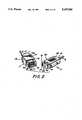
- FIG. 1is a perspective view of a male and female connector constructed in accordance with the present invention and with a medical apparatus.
- FIG. 2is a perspective view of the male and female connectors of the present invention showing the external configuration of the electrical and fluidic contact portions of both connectors.
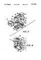
- FIG. 3is an exploded view of the male connector showing the internal configuration of an embodiment of the present invention.
- FIG. 4is an exploded view of the female connector in accordance with the present invention.
- FIG. 5is an enlarged cross-sectional view of the male and female connectors connected together in accordance with the present invention with the locking sleeve being shown in the locked position.
- FIG. 6is a cross-sectional view of the top shell of the present invention.
- FIG. 7is a cross-sectional view of one of the embodiments of a male core constructed in accordance with the present invention.
- FIG. 8is a cross-sectional view of one of the embodiments of a female core constructed in accordance with the present invention.
- FIG. 9is a cross-sectional view of the locking sleeve constructed in accordance with the present invention.
- FIG. 10is an enlarged cross-sectional view of male and female fluidic connectors constructed in accordance with the present invention.
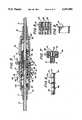
- FIG. 11is a perspective view showing an alternative embodiment of the pneumatic and electric connectors.
- FIG. 12is an enlarged cross-sectional view of the male and female connectors as they are being interconnected.
- FIG. 13is an enlarged cross-sectional view of the male and female connectors connected together with the locking sleeve being shown in the locked position.
- FIG. 14is an enlarged view of a male connector core located in the lower male shell piece and showing the connection of the end of the pneumatic-electrical cable to a tubular hollow pneumatic male pin and male electrical pins.
- FIG. 15is an enlargement showing the manner in which a consistent, bubble tight, fluidic connector is provided by a slight interference fit between tubular bottom male pneumatic pins and mating cylindrical openings formed in the female connector.
- FIG. 16is an enlargement showing in the manner in which the male pneumatic pin has sufficient flexibility to compensate for a small misalignment of the pin and the mating female opening.
- FIG. 17is a perspective view of a female connector for attachment to the housing of an instrument or the like.
- FIG. 18is a top planar view of the female connector of FIG. 17 attached to the wall of the housing.
- FIG. 19is a perspective view of an alternate embodiment of the present invention in operative engagement with a multi-purpose catheter, showing the male core in an exploded view.
- FIG. 20is a perspective view of an alternate embodiment of the present invention in operative engagement with a flow meter, showing the male core in an exploded view.
- FIG. 21Ais a flow chart diagram showing the sensor calibration steps of the connector shown in FIG. 19.
- FIG. 21Bis a flow chart diagram showing the sensor operation steps of the connector shown in FIG. 19.
- FIG. 22Ais a flow chart diagram showing the sensor calibration steps of the connector shown in FIG. 20.
- FIG. 22Bis a flow chart diagram showing the sensor operation steps of the connector shown in FIG. 20.
- FIG. 1shows a typical example of a medical apparatus utilizing male and female connectors constructed in accordance with the present invention.
- the connector 2 of the present inventioncomprises a male receptacle connector 3 and a female receptacle connector 4.
- the male connector 3is connected to an air flow transducer 7 through a pneumatic double-lumen tube 5.
- Exemplary embodiments of air flow transducer 7are disclosed and claimed in Applicant's copending patent application, Ser. No. 432,040, filed Nov. 6, 1989 now U.S. Pat. No. 5,033,312 for "Gas Flow Meter Housing” and Applicant's U.S. Pat. No. 4,989,456 for "Variable Area Obstruction Gas Flow Meters.”
- a female input connector 9 affixed to the housing of instrument 8has, advantageously, a similar structure as the female connector 4 for connection to another male connector 3 likewise constructed in accordance with the present invention.
- the female connector 4is connected to a measuring and monitoring instrument 8 through a cable 6 which is comprised of both one or more pneumatic tubes or lines and one or more electric wires from the transducer 7.
- the pneumatic electrical cable 6provides both fluidic lines for air flow data or fluidic data to the measuring and monitoring instrument 8 and electrical lines for electric signal data to the measuring and monitoring instrument 8.
- the measuring and monitoring instrument 8will typically measure and monitor air pressure, air flow rate of respiratory system.
- the instrument 8advantageously includes plural female input connectors 9.
- one of these other connectorscan be connected via pneumatic and electrical cables to a catheter, as described hereinabove with reference to U.S. Pat. No. 4,214,593 and pending U.S. patent application Ser. No. 515,370 now abandoned.
- the outer structure of the male and female connector of the present inventionis illustrated in FIG. 2.
- the male connector 3is formed of an upper male shell 13a, a lower male shell 13b, a strain relief bushing 11 and a slidable locking sleeve 14.
- the cable 5is advantageously a combination of pneumatic lumen and electric cables and is connected to the male connector 3 through stress relief 11.
- Each half of the male shells 13a, 13bincludes a flexible locking leaf or jaw 16 having a locking ridge 34, shown in FIG. 3, at the peripheral edge. As described below with reference to FIGS. 5, 12 and 13, this locking ridge is adopted to engage a slot in the female connector 4.
- the tip of the leaf 16(and thus the ridge 34) can be slightly moved up and down due to the elasticity of the plastic material forming the male shell 13.
- the locking sleeve 14slidably moves over the male shell 13 to lock the connection between the male connector 3 and female connector 4 by prohibiting the up down movement of the leaf 16.
- a ridge 36(FIG. 9) extends around the entire circumference of the sleeve 14 and facilitates holding onto the sleeve with the fingers of one hand so that the user may easily move it from an unlocked to locked position and from a locked to an unlocked position.
- the female connector 4is advantageously formed of a pair of female shells 20, a strain relief bushing 12 and a female core 21.
- the shell 20may be identical so as to lower the cost of manufacturing the parts and assembling same.
- a plurality of protrusions 42 on the female shell 20are preferably provided for eliminating slippage of the fingers when the user inserts the female connector into the male connector.
- the cable 6which advantageously includes a combination of pneumatic lumen and electric conductors is connected to the female connector 4 through strain relief bushing 12.
- this core 21provides a pair of pneumatic female receptacles 22 and a pair of female electrical receptacles 23, respectively, corresponding to the pneumatic male pins 17 and electrical male pins 18 in the male connector 3.
- the female core 21is extended from the female shells 20 so as to be inserted into the opening formed between the male shells 13a and 13b.
- the female core 21has formed, at one corner, a chamfer 41 having a predetermined angle on its one corner.
- the male shell 13has a triangular portion 40 which conforms with the chamfer 41 of the female core 21. Because of this combination of the chamfer 41 and the triangular portion 40, the correct position for interconnection of the male connector 3 and the female connector 4 is defined and a reverse insertion is prevented.
- FIG. 3shows an exploded view of the male connector 3 constructed in accordance with the present invention.
- the interiors of respective male shell members 13a and 13bare configured to accept and retain a male core member 19.
- this core 19supports both the male tubular pneumatic pins 17 and the male electrical pins 18.
- the male pneumatic pins 17are formed by an injection plastic mold so as to be integral with the core 19.
- the male electrical pins 18are separately inserted through passages 62, 63 (FIG. 7) into the male of core 19.
- Annular flanges 64, 65 in the passages 62, 63 (FIG. 7)engage and hold the electrical pins 18.
- interior ridges 43a and 44bposition the core 19 within the shells 13a and 13b.
- Another ridge 45 in each of the shells 13a and 13bsecures in place the strain relief bushing 11.
- the male connectoris assembled by first inserting the end of the pneumatic-electrical cable 5 through the strain relief bushing 11.
- the cable 5includes two pneumatic tubes, the respective ends of which are inserted into receptor sockets 61 (see FIG. 7) of the male core 19 and bonded into place.
- An alternative embodiment of the male connectoris shown in FIG. 14.
- the upper shell halfhas been removed and the cable 5a includes one pneumatic tube bonded into a single receptor socket communicating with a single male tubular pneumatic pin 17a.
- the cable 5aalso includes a pair of electrical leads 100, 101 which are respectively soldered to the inner ends 102, 103 of a pair of male electrical contact pins 17a, 17b.
- the male core 19is then fitted between the ridges 43 and 44b of the lower half shell 13b and the strain relief 11 is fitted within its core shaped projection 71 into the semi-round cutout 70 and its rectangular base 72 between the interior ridge 45 and the end wall 73 of the shell 13b.
- the upper half shell 13ais then snapped over the core 19 and strain relief 11.
- the male shell membersare semi-permanently held together by locking sleeve 14.
- the interior construction of the female connector 4is best seen in the exploded view of FIG. 4.
- the upper and lower female shells 20are identical in configuration and enclose a female core 21.
- the core(FIGS. 4 and 8) is generally rectangular in configuration and is enclosed by the shells within an inner chamber defined by interior ridge 48, the interior of the front wall 49 of the female shell 20, and that portion of the side wall which lies between ridge 48 and the front wall 49.
- the core 20advantageously includes a released portion 55 in both its upper and lower faces (see FIGS. 4 and 5) and the resultant edge ridges 110 lie within slots 57 formed in the front face of the shells 20.
- the strain relief bushing 12is positioned between the interior of the rear face of the shells 20 and interior ridge 50.
- the assembly of the female connectoris accomplished by passing the pneumatic-electrical cable 6 through the strain relief 12 and connecting the ends thereof to the respective pneumatic and electrical female receptacles 22, 23 carried by the female core 21. The entire female connector assembly is then snapped together and retained together by use of a suitable cement or adhesive.
- Locking sleeve 14advantageously performs several functions. As shown in FIGS. 3, 5, and 12, locking sleeve 14 is forced over an upper ridge 33 formed at the peripheral end of each of the leaves 16a, 16b. This is easily accomplished since, as best shown in FIGS. 5 and 12, the outer face 75 of each of the ridges 33 is beveled so that a force perpendicular to the plane of each leaf 16 is created when the locking edge of the sleeve 14 is pushed against these beveled ridges. This perpendicular force causes the cantilever ends of the leaves 16a, 16b to move towards each other and allow the entire sleeve 14 to slip over the respective ridges 33.
- the locking sleeveis retained in position by a ridge 46 formed in the top surface of the male half shells 13 and by the ridges 33 (which present a right angle edge 76 facing the end of the sleeve 14 after it has been mounted.
- that distance through which the sleeve 14 may be slid upon the male connectoris determined by the distance between ridge 46 and ridge 33.
- the locking sleeve 14locks together the upper and lower male shells 13a and 13b and thus provides a means to hold together these upper and lower shells without adhesive or cement while allowing the male core 19 to move slightly within the shell pieces and tolerate a certain amount of misalignment with respect to the mating female receptacle.
- the locking sleeve 14can be easily removed by manually squeezing together the ends of the flexible leaves 16a, 16b so that the ridges 33 clear the inside opening of the locking sleeve.
- FIG. 12illustrates a cross section of a male plug on the left being joined together with a female plug on the right and in FIGS. 5 and 13 which illustrate a cross section of the respective plugs after they have been joined together.
- FIG. 12the leading edge 80 of ridge 34 of leaves 16a and 16b is beveled so that the cantilever ends of the leaves 16a, 16b are forced apart by the front edges 81 of the female core 21.
- the ridges 34then slide along the respective top and bottom surfaces 82 of the female core until the ridge drops into an indentation 83 formed in the surfaces 82 by released portion 55 in the female core 20 (FIG. 4).
- Locking together of a male and female connectoris achieved by sliding the locking sleeve 14 until it abuts the ridge 33. As best shown in FIG. 13, the sleeve 14 is then held in its locked position by hemispherical bumps 90 located on the upper surfaces of the leaves 16a and 16b. The cantilevered ends of both of the leaves are then constrained from flexing away from the female core 21, and therefore the ridge 34 is "locked" against the shoulder 85 formed by the depressing of the beveled portion 55 with respect to the surface 42.
- a significant feature of the present inventionis the manner in which a consistent leak-tight interconnection is made between plural pneumatic lines.
- the tubular male pin 17 of the male core 19has a predetermined taper angle ⁇ thereabout most of its length with the exception of the end portion L where the pin 17 changes into a cylindrical end portion 120.
- This cylindrical end 120fits tightly into the female socket 22 formed in the female core 21.
- This socketstarts with a taper angle ⁇ greater than the taper angle ⁇ of the male pin.
- the male pin 17is guided very easily into insertion into the mouth of the female socket 22.
- the cylindrical portion 121 of this sockethas a slightly smaller (typically 0.001 to 0.002 inches) internal diameter than the outer diameter of the cylindrical end portion 120 thus creating an interference fit.
- the end portion 121 of the pneumatic pin 17is advantageously formed with a thin wall thickness of the radius of 0.010 inches so that the outer diameter of the plastic pin will compress to permit easy insertion thereof into the female socket 22 and provide the desired bubble tight interconnection.
- the male connectoris its ability to compensate for inaccuracies inherent in mass production of molded parts.
- the male coreis advantageously not cemented into the male shells 13.
- the male core 19is slightly movable within the male shells 13 since it is not bond®d to the male shells 13 with bond or adhesive.
- the male connector 3tolerates some misalignment with respect to the mating female connector 4.
- the pneumatic 17 and electric pins 18will more easily fit into the female connector 3.
- tubular male pneumatic pins 17In addition to the ability of the male core 19 itself to move within the male shells 13 is that the structure of the tubular male pneumatic pins 17, namely their long tapered wall, shown best in FIGS. 15 and 16, ranging typically from 0.017 down to 0.010 inches in thickness, gives these male pins 17 good flexibility so that the pins can very accurately align themselves to the female core receptacle socket 22.
- this male pneumatic pins 17is an important feature of the invention since it further compensates for small misalignments which are inherent in low cost manufacturing of plastic molded parts. This feature is best illustrated in the enlarged detail section of FIG. 15 showing a two-port pneumatic connection. If the center-to-center distances S M and S F for spacing of the male pins 17a, 17b and female sockets 22a, 22b are not precisely identical, the male pins 17a, 17b will bend slightly to compensate for the misalignment which maintains a leak-tight connection. The preferred amount of flexure for each is in the range of 0.005 to 0.008 inch per pin.
- the connectordoes not require a precise engagement depth for tight connection. It is sufficient if only a portion of the total length "L" of the cylindrical area is engaged and the end of the pneumatic pin 17 need not reach the bottom within the female receptacle 22. As shown in FIG. 10, there remains, after leak tight connection is established, a distance D between the end of the male pneumatic pin 17 and the bottom of the female cylinder 121 in the final receptacle 22. Distance D is typically of the order of 0.03 inches. This distance D permits extra travel of the male pin into the female receptacle to accommodate clearances and tolerances necessary for a proper function of the locking mechanism.
- a further advantage of the inventionis that since the faces of the male pin 17 and the female receptacle 22 do not have to be in full contact and since the female receptacle socket 22 has a larger taper angle than the flexible male pin 7, the connector can tolerate an angular misalignment ⁇ of several degrees without loosing a tight seal around the connections.
- the connector of this inventioncan advantageously be used as a panel mounted receptacle 9.
- the preferred construction of this receptacleis illustrated in FIGS. 17 and 18 which illustrates a bezel 130 for receiving any female core 21 of desired configuration.
- the female core 21is installed in the flanged bezel 130 and mounted to an instrument panel 40. Correct orientation of male and female parts of the connector is ensured by the indexing key 41 on the female core which matches the same shape key shown in FIG. 2.
- FIGS. 1-4illustrate the interconnection of two pneumatic and two electrical conductors.
- FIG. 14illustrates the male connector for interconnection of one pneumatic and two electrical conductors.
- FIG. 11illustrates a male core 140 and female core 141 identical with the cores illustrated in FIGS. 3 and 14 and described above except that male core 140 and female core 141 provide for simultaneous interconnection of a single pneumatic line (when the male pneumatic pin 17a is inserted into the female receptacle 22a) and four electrical conductors (when the four male electrical pins 18a are inserted into the four female receptacles 23a).
- FIGS. 19 and 20an alternate embodiment of the connector of the present invention is shown, generally designated 200.
- the connector 200is substantially identical to the connector 2 shown in FIG. 1, with the exception that the male core 202 of the connector 200 includes an electronic microchip memory 204 which is mounted on the male core 202.
- the memory 204can advantageously be solvent bonded to the male core 202.
- the memory 204is an electronically erasable programmable read-write memory (EEPROM) having a capacity of one thousand (1K) or two thousand (2K) bits of data.
- EEPROMelectronically erasable programmable read-write memory
- the memory 204is electrically connected to at least two or more electrical connector pins of the male core 202. More specifically, the memory 204 is electrically connected to the electrical connector pins 206, 208 of the male core 202. Accordingly, the memory chip 204 can be located inside a connector which is attached to a sensor, such as the flow meter 221 shown in FIG. 20 or the thermistor 210 or pH sensing chip 219 of a multiple function catheter 211, shown in FIG. 19.
- the thermistor 210can be any suitable temperature sensing device well-known in the art.
- the pH sensing chip 219can be any device suitable for in vivo sensing of the pH of a patient.
- the flow meter 221, shown in FIG. 20,can be the type of device disclosed in U.S. Pat. No. 4,989,456.
- the memory 204can be connected to a calibration computer 212 by attaching the female core 213 of the female receptacle connector 214 to the male core 202 and electrically connecting the computer 212 to the female core 213 via lines 215. It is to be understood that while the disclosure above discusses a memory 204 that is associated with the male core 202, the memory 204 can alternately be associated with the female core 214. It is to be further understood that sensors other than the thermistor 210 or pH sensing chip 219 can be associated with the connector 200.
- FIGS. 19, 21A, and 21BIn describing the operation of the connector 200 when the connector 200 is associated with either or both of the thermistor 210 and pH sensing chip 219, cross-reference is made to FIGS. 19, 21A, and 21B.
- the electrical connector pins 206, 208 of the male core 202are electrically connected to the memory chip 204 and the thermistor 210, and the female core 213 is electrically connected to the calibration computer 212. Then, the male core 202 is engaged with the female core 213, as indicated at block 218.
- the calibration computer 212can be programmed to ascertain the response characteristics of the thermistor 210. More particularly, the thermistor can be placed in a test environment, the temperature and temperature variation of which is known to the calibration computer 212. The calibration computer 212 receives a signal representative of the temperature of the test environment from the thermistor 210 through the connector 200, and compares this signal with the true temperature of the test environment, as indicated at block 220. Based upon the comparison in block 220, the calibration computer 212 ascertains the response characteristics of the thermistor 210, as indicated at block 221.
- the computer 212stores the response characteristics in the memory 204. If desired, additional data can be stored in the memory 204, e.g., date of sensor manufacture, sensor lot number, and sensor serial number.
- the female core 213is then disengaged from the male core 202.
- the catheter 211 with thermistor 210is introduced into the body of the patient by means well-known in the art, as indicated at block 224 of FIG. 21B.
- the male core 202can be engaged with the female core 213, and the female core 213 electrically connected to a diagnostic computer (not shown), as indicated at block 226.
- the patient temperature signal from the thermistor 210is conducted through the connector 200 to the diagnostic computer.
- the diagnostic computeris programmed to query the memory 204 to ascertain the response characteristics of the thermistor 210. Based upon the response characteristics of the thermistor 210, the diagnostic computer applies a correction factor to the signal from the thermistor 210, i.e., "calibrates" the signal from the thermistor 210, to determine an accurate value for the temperature of the patient. This step is indicated at block 230 in FIG. 21B.
- the male coreis connected to the flow meter 221.
- the male coreis connected to the female core 213.
- the female core 213is in fluid communication with a pressure transducer that is advantageously housed with the calibration computer 212.
- the female core 213is electrically connected to the calibration computer 212, and the pressure transducer is electrically connected to the calibration computer 212.
- a preselected volume of airis directed through the flow meter 221 at a preselected rate.
- the volume and flow rate of the airare known to the computer 212.
- the pressure transducergenerates an electrical signal representative of the air flow rate through the flow meter 221, as sensed by the flow meter 221.
- the computer 212compares the signal from the pressure transducer with the actual air flow rate, and ascertains the response characteristic of the flow meter 221, as indicated at block 238.
- the computer 212stores the response characteristic of the flow meter 221 in the memeory 204, along with other predetermined data, e.g., flow meter date of manufacture, lot number, and serial number.
- the male core 202is then disengaged from the female core 213.
- the flow meter 221is introduced into a patient, as indicated at block 242 in FIG. 22B. Then, the male core 202 can be engaged with a female core (not shown), which is in turn in fluid communication with a pressure transducer (not shown) similar to the transducer discussed above and which is also electrically connected to a diagnostic computer (also not shown), as indicated at block 244.
- the diagnostic computerreceives the electrical signal from the transducer that is representative of the patient's air flow rate, as sensed by the flow meter 221. As indicated at block 246, the diagnostic computer queries the memory 204 to ascertain the response characteristic of the flow meter 221. Consequently, as indicated at block 248, the diagnostic computer can apply a correction factor to the signal from the pressure transducer which is representative of the response characteristic of the flow meter 204.
- the connector 200 with memory 204permits the use of a sensor having a relatively large measurement accuracy tolerance.
- the flow meter 221, pH sensing chip 219, or thermistor 210need not be manufactured according to a comparatively precise response characteristic, because the response characteristic of each individual sensor can be ascertained and stored on the memory 204 of the male core 202 that is associated with the particular sensor, for subsequent retrieval by a diagnostic computer during use of the particular sensor.
Landscapes
- Health & Medical Sciences (AREA)
- Life Sciences & Earth Sciences (AREA)
- Medical Informatics (AREA)
- Molecular Biology (AREA)
- Pulmonology (AREA)
- Biophysics (AREA)
- Pathology (AREA)
- Engineering & Computer Science (AREA)
- Biomedical Technology (AREA)
- Heart & Thoracic Surgery (AREA)
- Physiology (AREA)
- Physics & Mathematics (AREA)
- Surgery (AREA)
- Animal Behavior & Ethology (AREA)
- General Health & Medical Sciences (AREA)
- Public Health (AREA)
- Veterinary Medicine (AREA)
- Infusion, Injection, And Reservoir Apparatuses (AREA)
- Connector Housings Or Holding Contact Members (AREA)
- Measurement Of The Respiration, Hearing Ability, Form, And Blood Characteristics Of Living Organisms (AREA)
- External Artificial Organs (AREA)
Abstract
Description
Claims (16)
Priority Applications (10)
| Application Number | Priority Date | Filing Date | Title |
|---|---|---|---|
| US07/698,589US5197895A (en) | 1991-05-10 | 1991-05-10 | Disposable electro-fluidic connector with data storage |
| AT92913247TATE185927T1 (en) | 1991-05-10 | 1992-05-08 | DISPOSABLE ELECTROFLUIDIC CONNECTOR WITH DATA STORAGE |
| PCT/US1992/004034WO1992021163A1 (en) | 1991-05-10 | 1992-05-08 | Disposable electro-fluidic connector with data storage |
| DE69230173TDE69230173T2 (en) | 1991-05-10 | 1992-05-08 | DISPOSABLE ELECTROFLUIDIC CONNECTOR WITH DATA STORAGE |
| CA002447917ACA2447917C (en) | 1991-05-10 | 1992-05-08 | Disposable electro-fluidic connector with data storage |
| JP50018293AJP3315406B2 (en) | 1991-05-10 | 1992-05-08 | Electric fluid disposable connector with data retention |
| EP92913247AEP0583409B1 (en) | 1991-05-10 | 1992-05-08 | Disposable electro-fluidic connector with data storage |
| CA002109219ACA2109219C (en) | 1991-05-10 | 1992-05-08 | Disposable electro-fluidic connector with data storage |
| US07/998,400US5405269A (en) | 1991-05-10 | 1993-02-26 | Disposable electro-fluidic connector with data storage |
| JP2002032416AJP2002282361A (en) | 1991-05-10 | 2002-02-08 | Diposable connector of electricity-fluid provided with data retainer |
Applications Claiming Priority (1)
| Application Number | Priority Date | Filing Date | Title |
|---|---|---|---|
| US07/698,589US5197895A (en) | 1991-05-10 | 1991-05-10 | Disposable electro-fluidic connector with data storage |
Related Child Applications (1)
| Application Number | Title | Priority Date | Filing Date |
|---|---|---|---|
| US07/998,400DivisionUS5405269A (en) | 1991-05-10 | 1993-02-26 | Disposable electro-fluidic connector with data storage |
Publications (1)
| Publication Number | Publication Date |
|---|---|
| US5197895Atrue US5197895A (en) | 1993-03-30 |
Family
ID=24805874
Family Applications (2)
| Application Number | Title | Priority Date | Filing Date |
|---|---|---|---|
| US07/698,589Expired - LifetimeUS5197895A (en) | 1991-05-10 | 1991-05-10 | Disposable electro-fluidic connector with data storage |
| US07/998,400Expired - LifetimeUS5405269A (en) | 1991-05-10 | 1993-02-26 | Disposable electro-fluidic connector with data storage |
Family Applications After (1)
| Application Number | Title | Priority Date | Filing Date |
|---|---|---|---|
| US07/998,400Expired - LifetimeUS5405269A (en) | 1991-05-10 | 1993-02-26 | Disposable electro-fluidic connector with data storage |
Country Status (7)
| Country | Link |
|---|---|
| US (2) | US5197895A (en) |
| EP (1) | EP0583409B1 (en) |
| JP (2) | JP3315406B2 (en) |
| AT (1) | ATE185927T1 (en) |
| CA (1) | CA2109219C (en) |
| DE (1) | DE69230173T2 (en) |
| WO (1) | WO1992021163A1 (en) |
Cited By (133)
| Publication number | Priority date | Publication date | Assignee | Title |
|---|---|---|---|---|
| US5362248A (en)* | 1992-02-03 | 1994-11-08 | Japan Aviation Electronics Industry, Ltd. | Connector capable of automatically and reliably inhibiting disengagement of mehanical coupling between connection members |
| US5383794A (en)* | 1993-07-16 | 1995-01-24 | The Whitaker Corporation | Latch actuator for a connector |
| USD357736S (en) | 1993-09-16 | 1995-04-25 | The Kendall Company | Connector for device for applying compressive pressure to the leg |
| US5437650A (en)* | 1993-03-23 | 1995-08-01 | Abbott Laboratories | Securing collar for cannula connector |
| US5479066A (en)* | 1993-03-31 | 1995-12-26 | U.S. Philips Corporation | Electric lamp |
| USD369664S (en) | 1993-09-16 | 1996-05-07 | The Kendall Company | Connector for device for applying compressive pressure to the leg |
| US5573414A (en)* | 1995-03-16 | 1996-11-12 | Mechanical Dynamics & Analysis, Inc. | Two piece electrical and fluidic connector and installation method therefore |
| USD385255S (en)* | 1995-08-21 | 1997-10-21 | Honda Tsushin Kogyo Kabushiki Kaisha | Connector with a lock mechanism |
| US5694926A (en) | 1994-10-14 | 1997-12-09 | Bird Products Corporation | Portable drag compressor powered mechanical ventilator |
| US5713752A (en)* | 1995-07-21 | 1998-02-03 | The Whitaker Corporation | Latchable electrical connector |
| US5779495A (en)* | 1995-08-26 | 1998-07-14 | Molex Incorporated | Electrical connector with improved latching system |
| US5925831A (en)* | 1997-10-18 | 1999-07-20 | Cardiopulmonary Technologies, Inc. | Respiratory air flow sensor |
| USD413825S (en)* | 1998-09-14 | 1999-09-14 | Cardiopulmonary Technologies, Inc. | Respiratory air flow measuring device |
| USD416623S (en) | 1997-12-22 | 1999-11-16 | Incutech, Inc. | Multi-lumen catheter connector |
| US5993240A (en)* | 1997-07-29 | 1999-11-30 | Ericsson Inc. | Retention and strain relief apparatus for connecting two devices |
| WO2000018304A2 (en) | 1998-09-25 | 2000-04-06 | Sherwood Services Ag | Surgical system console |
| US6126610A (en)* | 1997-11-03 | 2000-10-03 | Novametrix Medical Systems, Inc. | Pneumatic connector with encoding |
| US6135967A (en) | 1999-04-26 | 2000-10-24 | Fiorenza; Anthony Joseph | Respiratory ventilator with automatic flow calibration |
| US6168446B1 (en)* | 1998-09-25 | 2001-01-02 | Hon Hai Precision Ind. Co., Ltd. | Electronic card connector having an improved card release mechanism |
| US6203502B1 (en) | 1997-03-31 | 2001-03-20 | Pryon Corporation | Respiratory function monitor |
| US6222127B1 (en)* | 1992-09-21 | 2001-04-24 | Spd Technologies, Inc. | Compact electrical bus |
| US6240919B1 (en) | 1999-06-07 | 2001-06-05 | Macdonald John J. | Method for providing respiratory airway support pressure |
| USD453921S1 (en) | 2001-07-27 | 2002-02-26 | Medserve Group, Inc. | Instrument connector |
| US6392546B1 (en) | 2000-09-07 | 2002-05-21 | Judson L. Smith | Hand washing compliance measurement and recording system |
| US6471530B1 (en)* | 1999-04-15 | 2002-10-29 | A. Raymond & Cie | Plug-and-socket connection for water-cooled, current-bearing lines for tools |
| US20030046493A1 (en)* | 2001-08-31 | 2003-03-06 | Coulson Richard L. | Hardware updated metadata for non-volatile mass storage cache |
| US20030106554A1 (en)* | 2001-11-30 | 2003-06-12 | De Silva Adrian D. | Gas identification system and volumetric ally correct gas delivery system |
| US6685491B2 (en)* | 2001-03-15 | 2004-02-03 | Frank Gergek | Combined connector for fluid and electrical connection |
| WO2004015834A1 (en)* | 2002-08-02 | 2004-02-19 | Barral Guillermo Fabian | System of electric modules with inner multi-purpose conduit |
| US6725342B1 (en) | 2000-09-26 | 2004-04-20 | Intel Corporation | Non-volatile mass storage cache coherency apparatus |
| US6722211B1 (en) | 2001-11-29 | 2004-04-20 | Viasys Healthcare, Critical Care Division | Multi-stage variable orifice flow obstruction sensor |
| US6785767B2 (en) | 2000-12-26 | 2004-08-31 | Intel Corporation | Hybrid mass storage system and method with two different types of storage medium |
| US20040207529A1 (en)* | 2003-04-16 | 2004-10-21 | Ge Medical Systems Information Technologies, Inc. | Apparatus for monitoring gas concentrations |
| US20040254491A1 (en)* | 2003-06-13 | 2004-12-16 | Cardiopulmonary Technologies, Inc. | Gas flow diverter for respiratory monitoring device |
| US20050068726A1 (en)* | 2003-09-25 | 2005-03-31 | Harris Corporation | Electro-fluidic device and interconnect and related methods |
| US6883563B2 (en) | 2001-07-26 | 2005-04-26 | Judson L. Smith | Apparatus and method to monitor the usage of a network system of personal hand sanitizing dispensers |
| USD512648S1 (en) | 2004-12-15 | 2005-12-13 | Smith Judson L | Dispenser for fluid material |
| US20060264113A1 (en)* | 2004-09-27 | 2006-11-23 | Zauber Vonn A | Rugged, removable, electronic device |
| US20070049870A1 (en)* | 2001-05-18 | 2007-03-01 | Deka Products Limited Partnership | Infusion Set for a Fluid Pump |
| US20070053158A1 (en)* | 2005-08-12 | 2007-03-08 | Harris Corporation | Electro-fluidic interconnect attachment |
| US20070157930A1 (en)* | 2006-01-10 | 2007-07-12 | Viasys Manufacturing, Inc. | System and method for circuit compliance compensated volume assured pressure control in a patient respiratory ventilator |
| US20070219597A1 (en)* | 2006-02-09 | 2007-09-20 | Dean Kamen | Adhesive and peripheral systems and methods for medical devices |
| US20080163669A1 (en)* | 2006-12-22 | 2008-07-10 | Griffin Analytical Technologies, Llc. | Interface port for connection of a sampling device to an analytical instrument |
| US20090099523A1 (en)* | 2001-05-18 | 2009-04-16 | Grant Kevin L | Infusion pump assembly |
| US20090224529A1 (en)* | 2006-03-13 | 2009-09-10 | Renishaw Plc | Fluid Connector for Fluid Delivery Apparatus |
| US7597122B1 (en) | 2001-07-26 | 2009-10-06 | Smith Judson L | Apparatus and method to monitor the usage of a network system of personal hand sanitizing dispensers |
| US20090275896A1 (en)* | 2007-02-09 | 2009-11-05 | Dean Kamen | Infusion pump assembly |
| US20090281497A1 (en)* | 2007-12-31 | 2009-11-12 | Dean Kamen | Wearable pump assembly |
| US20100094222A1 (en)* | 2008-10-10 | 2010-04-15 | Grant Kevin L | Infusion pump assembly |
| US20100089475A1 (en)* | 2008-10-10 | 2010-04-15 | Tracey Brian D | Medium connector |
| US20100094221A1 (en)* | 2008-10-10 | 2010-04-15 | Spencer Geoffrey P | Multi-language / multi-processor infusion pump assembly |
| US20100094215A1 (en)* | 2008-10-10 | 2010-04-15 | Grant Kevin L | Pump assembly with a removable cover assembly |
| DE10354147B4 (en)* | 2003-11-19 | 2011-01-27 | Richard Wolf Gmbh | Medical connector device with a plug and a coupling |
| US8066672B2 (en) | 2008-10-10 | 2011-11-29 | Deka Products Limited Partnership | Infusion pump assembly with a backup power supply |
| US20120064745A1 (en)* | 2007-06-05 | 2012-03-15 | Martin Ottliczky | Hybrid universal distribution system comprising electrical, fluid, and communication functions |
| US8223028B2 (en) | 2008-10-10 | 2012-07-17 | Deka Products Limited Partnership | Occlusion detection system and method |
| US20120184141A1 (en)* | 2010-10-22 | 2012-07-19 | Adc Telecommunications, Inc. | Contact set arrangement for right angle jack |
| US20120208401A1 (en)* | 2010-10-22 | 2012-08-16 | Adc Telecommunications, Inc. | Plug contact arrangement and the manufacture thereof |
| US20130187381A1 (en)* | 2012-01-24 | 2013-07-25 | Industrie Borla S.P.A. | Connector for medical lines |
| CN103349813A (en)* | 2012-02-22 | 2013-10-16 | 厄比电子医学有限责任公司 | Fluid connector with multiple radially shiftable connector elements |
| US20140038458A1 (en)* | 2012-07-31 | 2014-02-06 | Harris Corporation | Electrical connector |
| US8715012B2 (en) | 2011-04-15 | 2014-05-06 | Adc Telecommunications, Inc. | Managed electrical connectivity systems |
| US20140188086A1 (en)* | 2012-12-31 | 2014-07-03 | Biosense Webster (Israel), Ltd. | Catheter connector |
| US9093796B2 (en) | 2012-07-06 | 2015-07-28 | Adc Telecommunications, Inc. | Managed electrical connectivity systems |
| US9180245B2 (en) | 2008-10-10 | 2015-11-10 | Deka Products Limited Partnership | System and method for administering an infusible fluid |
| US9203198B2 (en) | 2012-09-28 | 2015-12-01 | Commscope Technologies Llc | Low profile faceplate having managed connectivity |
| US20160106967A1 (en)* | 2013-05-29 | 2016-04-21 | Industrie Borla S.P.A. | Connector for medical lines |
| US20170368325A1 (en)* | 2015-03-11 | 2017-12-28 | Terumo Kabushiki Kaisha | Connector and medical device set |
| US20180062313A1 (en)* | 2015-05-21 | 2018-03-01 | Hewlett-Packard Development Company, Lp. | Holder to Constrain Elastic Members of a Receptacle |
| US20180064870A1 (en)* | 2012-07-03 | 2018-03-08 | Milestone Scientific, Inc. | Disposable assembly for drug infusion with pressure sensing for identification of and injection into fluid-filled anatomic spaces |
| US10842966B2 (en) | 2015-10-16 | 2020-11-24 | Milestone Scientific, Inc. | Apparatus for assisting a user in advancing a needle into a subject at a selected rate |
| US20200390589A1 (en)* | 2018-02-20 | 2020-12-17 | Coloplast A/S | Sensor assembly part and a base plate and a medical pouch for a medical appliance and a device for connecting to a base plate and/or a sensor assembly part |
| US10960141B1 (en) | 2019-05-16 | 2021-03-30 | Milestone Scientific, Inc. | Device and method for identification of a target region |
| US11027108B2 (en) | 2017-11-14 | 2021-06-08 | Sartorius Stedim North America Inc. | Fluid transfer assembly with a junction having multiple fluid pathways |
| US11108190B2 (en)* | 2019-02-25 | 2021-08-31 | Foxconn (Kunshan) Computer Connector Co., Ltd. | Electrical connector mating port enclosed by inner sleeve and outer cover |
| US11319201B2 (en) | 2019-07-23 | 2022-05-03 | Sartorius Stedim North America Inc. | System for simultaneous filling of multiple containers |
| US11364335B2 (en) | 2006-02-09 | 2022-06-21 | Deka Products Limited Partnership | Apparatus, system and method for fluid delivery |
| US11395877B2 (en) | 2006-02-09 | 2022-07-26 | Deka Products Limited Partnership | Systems and methods for fluid delivery |
| US11404776B2 (en) | 2007-12-31 | 2022-08-02 | Deka Products Limited Partnership | Split ring resonator antenna adapted for use in wirelessly controlled medical device |
| US11426512B2 (en) | 2006-02-09 | 2022-08-30 | Deka Products Limited Partnership | Apparatus, systems and methods for an infusion pump assembly |
| WO2022180517A1 (en)* | 2021-02-26 | 2022-09-01 | Fisher & Paykel Healthcare Limited | Respiratory or surgical humidifier and components thereof |
| US20220313473A1 (en)* | 2019-06-26 | 2022-10-06 | Coloplast A/S | Device for connecting a base plate and/or a sensor patch for a medical device |
| US11471595B2 (en) | 2017-05-04 | 2022-10-18 | Milestone Scientific, Inc. | Method and apparatus for performing a peripheral nerve block |
| US11478623B2 (en) | 2006-02-09 | 2022-10-25 | Deka Products Limited Partnership | Infusion pump assembly |
| US11497846B2 (en) | 2006-02-09 | 2022-11-15 | Deka Products Limited Partnership | Patch-sized fluid delivery systems and methods |
| US11497686B2 (en) | 2007-12-31 | 2022-11-15 | Deka Products Limited Partnership | Apparatus, system and method for fluid delivery |
| US20220384067A1 (en)* | 2020-04-14 | 2022-12-01 | Instrument Manufacturing Company | Systems and Methods for Injecting Electrical Cables with A Fluid |
| US11523972B2 (en) | 2018-04-24 | 2022-12-13 | Deka Products Limited Partnership | Apparatus, system and method for fluid delivery |
| US11524151B2 (en) | 2012-03-07 | 2022-12-13 | Deka Products Limited Partnership | Apparatus, system and method for fluid delivery |
| US11534542B2 (en) | 2007-12-31 | 2022-12-27 | Deka Products Limited Partnership | Apparatus, system and method for fluid delivery |
| US11547493B2 (en)* | 2018-12-17 | 2023-01-10 | Acclarent, Inc. | Connector to couple surgical instrument with navigation system |
| US11577953B2 (en) | 2017-11-14 | 2023-02-14 | Sartorius Stedim North America, Inc. | System for simultaneous distribution of fluid to multiple vessels and method of using the same |
| US11584571B2 (en) | 2011-06-22 | 2023-02-21 | Sartorius Stedim North America Inc. | Vessel closures and methods for using and manufacturing same |
| US11597541B2 (en) | 2013-07-03 | 2023-03-07 | Deka Products Limited Partnership | Apparatus, system and method for fluid delivery |
| US11642283B2 (en) | 2007-12-31 | 2023-05-09 | Deka Products Limited Partnership | Method for fluid delivery |
| US11691866B2 (en) | 2017-11-14 | 2023-07-04 | Sartorius Stedim North America Inc. | System for simultaneous distribution of fluid to multiple vessels and method of using the same |
| US11701248B2 (en) | 2017-12-22 | 2023-07-18 | Coloplast A/S | Accessory devices of a medical system, and related methods for communicating leakage state |
| US11707377B2 (en) | 2017-12-22 | 2023-07-25 | Coloplast A/S | Coupling part with a hinge for a medical base plate and sensor assembly part |
| US11707376B2 (en) | 2017-12-22 | 2023-07-25 | Coloplast A/S | Base plate for a medical appliance and a sensor assembly part for a base plate and a method for manufacturing a base plate and sensor assembly part |
| US11717433B2 (en) | 2017-12-22 | 2023-08-08 | Coloplast A/S | Medical appliance with angular leakage detection |
| US11723841B2 (en) | 2007-12-31 | 2023-08-15 | Deka Products Limited Partnership | Apparatus, system and method for fluid delivery |
| US11730622B2 (en) | 2017-12-22 | 2023-08-22 | Coloplast A/S | Medical appliance with layered base plate and/or sensor assembly part and related methods |
| US11786392B2 (en) | 2017-12-22 | 2023-10-17 | Coloplast A/S | Data collection schemes for an ostomy appliance and related methods |
| US11819443B2 (en) | 2017-12-22 | 2023-11-21 | Coloplast A/S | Moisture detecting base plate for a medical appliance and a system for determining moisture propagation in a base plate and/or a sensor assembly part |
| US11844718B2 (en) | 2017-12-22 | 2023-12-19 | Coloplast A/S | Medical device having a monitor mechanically and electrically attachable to a medical appliance |
| US11865029B2 (en) | 2017-12-22 | 2024-01-09 | Coloplast A/S | Monitor device of a medical system having a connector for coupling to both a base plate and an accessory device |
| US11872154B2 (en) | 2017-12-22 | 2024-01-16 | Coloplast A/S | Medical appliance system, monitor device, and method of monitoring a medical appliance |
| US11890448B2 (en) | 2006-02-09 | 2024-02-06 | Deka Products Limited Partnership | Method and system for shape-memory alloy wire control |
| US11890219B2 (en) | 2014-04-17 | 2024-02-06 | Coloplast A/S | Thermoresponsive skin barrier appliances |
| US11918506B2 (en) | 2017-12-22 | 2024-03-05 | Coloplast A/S | Medical appliance with selective sensor points and related methods |
| US11931285B2 (en) | 2018-02-20 | 2024-03-19 | Coloplast A/S | Sensor assembly part and a base plate for a medical appliance and a device for connecting to a base plate and/or a sensor assembly part |
| US11964126B2 (en) | 2006-02-09 | 2024-04-23 | Deka Products Limited Partnership | Infusion pump assembly |
| US11986418B2 (en) | 2017-12-22 | 2024-05-21 | Coloplast A/S | Medical system and monitor device with angular leakage detection |
| US11998474B2 (en) | 2018-03-15 | 2024-06-04 | Coloplast A/S | Apparatus and methods for navigating ostomy appliance user to changing room |
| US12029582B2 (en) | 2018-02-20 | 2024-07-09 | Coloplast A/S | Accessory devices of a medical system, and related methods for changing a medical appliance based on future operating state |
| US12064590B2 (en) | 2006-02-09 | 2024-08-20 | Deka Products Limited Partnership | Patch-sized fluid delivery systems and methods |
| US12070574B2 (en) | 2006-02-09 | 2024-08-27 | Deka Products Limited Partnership | Apparatus, systems and methods for an infusion pump assembly |
| US12096957B2 (en) | 2020-04-24 | 2024-09-24 | Milestone Scientific, Inc. | Device and method for needle/catheter location utilizing correlation analysis |
| US12151080B2 (en) | 2006-02-09 | 2024-11-26 | Deka Products Limited Partnership | Adhesive and peripheral systems and methods for medical devices |
| US12171572B2 (en) | 2017-12-22 | 2024-12-24 | Coloplast A/S | Accessory devices of a medical system, and related methods for communicating operating state |
| US12178736B2 (en) | 2017-12-22 | 2024-12-31 | Coloplast A/S | Ostomy system base plate including electrical terminals and a coupling part attachable to a monitor device |
| US12178740B2 (en) | 2017-12-22 | 2024-12-31 | Coloplast A/S | Leakage detection in an ostomy device |
| US12178739B2 (en) | 2017-12-22 | 2024-12-31 | Coloplast A/S | Ostomy appliance having an electrical connector |
| US12186531B2 (en) | 2008-10-10 | 2025-01-07 | Deka Products Limited Partnership | Infusion pump assembly |
| US12226229B2 (en) | 2018-03-15 | 2025-02-18 | Coloplast A/S | Methods of configuring ostomy notifications and related accessory devices |
| US12232997B2 (en) | 2018-08-15 | 2025-02-25 | Coloplast A/S | Accessory device of a medical system and related methods for issue identification |
| US12239127B2 (en) | 2021-07-28 | 2025-03-04 | Sartorius Stedim North America Inc. | Thermal capacitors, systems, and methods for rapid freezing or heating of biological materials |
| US12252391B2 (en) | 2017-11-14 | 2025-03-18 | Sartorius Stedim North America Inc. | System for simultaneous distribution of fluid to multiple vessels and method of using the same |
| US12272449B2 (en) | 2017-12-22 | 2025-04-08 | Coloplast A/S | Data transmission schemes for a medical system, monitor device for a medical appliance and related methods |
| US12274857B2 (en) | 2006-02-09 | 2025-04-15 | Deka Products Limited Partnership | Method and system for shape-memory alloy wire control |
| US12370327B2 (en) | 2008-10-10 | 2025-07-29 | Deka Products Limited Partnership | Infusion pump methods, systems and apparatus |
| WO2025157962A1 (en)* | 2024-01-25 | 2025-07-31 | Treefrog Therapeutics | Alignment device |
| US12433781B2 (en) | 2017-12-22 | 2025-10-07 | Coloplast A/S | Tools and methods for placing an ostomy appliance on a user |
Families Citing this family (79)
| Publication number | Priority date | Publication date | Assignee | Title |
|---|---|---|---|---|
| DE4327446C1 (en)* | 1993-08-14 | 1994-09-08 | Jedermann & Pohl Gmbh | Instrument for measuring the maximum flow quantity during expiration |
| FR2712737B1 (en)* | 1993-11-19 | 1996-01-12 | Sextant Avionique | Mixed connector with electrofluidic pins. |
| DE19546952C2 (en)* | 1994-12-17 | 1999-06-17 | Horiba Ltd | Gas analyzer rack assembly |
| DE29508480U1 (en)* | 1995-05-22 | 1996-09-19 | Interconnectron GmbH, 94469 Deggendorf | Electrical connector with fluid feedthrough |
| US5566680A (en)* | 1995-09-22 | 1996-10-22 | Graphic Controls Corporation | Transducer-tipped intrauterine pressure catheter system |
| US5660567A (en)* | 1995-11-14 | 1997-08-26 | Nellcor Puritan Bennett Incorporated | Medical sensor connector with removable encoding device |
| DE19622528C2 (en)* | 1996-06-05 | 2001-03-08 | Mannesmann Vdo Ag | Injection molding closure cap made of plastic |
| US6099481A (en) | 1997-11-03 | 2000-08-08 | Ntc Technology, Inc. | Respiratory profile parameter determination method and apparatus |
| US6298255B1 (en) | 1999-06-09 | 2001-10-02 | Aspect Medical Systems, Inc. | Smart electrophysiological sensor system with automatic authentication and validation and an interface for a smart electrophysiological sensor system |
| US6708049B1 (en)* | 1999-09-28 | 2004-03-16 | Nellcor Puritan Bennett Incorporated | Sensor with signature of data relating to sensor |
| DE10026769C2 (en)* | 2000-06-04 | 2003-03-06 | Frank Prochiner | Connection construction for connecting components |
| AUPS315002A0 (en)* | 2002-06-25 | 2002-07-18 | Resmed Limited | Method & apparatus for control of appliance coupler retention and withdrawal forces |
| ATE479343T1 (en) | 2002-10-01 | 2010-09-15 | Nellcor Puritan Bennett Inc | USE OF A HEADBAND FOR VOLTAGE DISPLAY AND SYSTEM OF OXYMETER AND HEADBAND |
| US7698909B2 (en) | 2002-10-01 | 2010-04-20 | Nellcor Puritan Bennett Llc | Headband with tension indicator |
| US7084782B2 (en)* | 2002-12-23 | 2006-08-01 | Halliburton Energy Services, Inc. | Drill string telemetry system and method |
| US7047056B2 (en) | 2003-06-25 | 2006-05-16 | Nellcor Puritan Bennett Incorporated | Hat-based oximeter sensor |
| US8412297B2 (en) | 2003-10-01 | 2013-04-02 | Covidien Lp | Forehead sensor placement |
| DE102004022503A1 (en)* | 2004-03-23 | 2005-10-13 | Micro-Epsilon Messtechnik Gmbh & Co Kg | Non-contact sensor |
| US7604602B2 (en)* | 2004-07-08 | 2009-10-20 | Edwards Lifesciences Corporation | Disposable blood pressure transducer and monitor interface |
| US6951474B1 (en)* | 2004-07-22 | 2005-10-04 | Hon Hai Precision Ind. Co., Ltd. | Cable end connector assembly having pulling device |
| EP4049703B1 (en) | 2004-08-20 | 2023-09-27 | Fisher & Paykel Healthcare Limited | Apparatus for measuring properties of gases supplied to a patient |
| US8277386B2 (en)* | 2004-09-27 | 2012-10-02 | Volcano Corporation | Combination sensor guidewire and methods of use |
| JP4653221B2 (en)* | 2005-07-25 | 2011-03-16 | エフシーアイ | Electrical connection device provided with fitting state instruction means |
| DE102005037864B4 (en)* | 2005-08-10 | 2008-11-27 | Schaltbau Gmbh | charging connectors |
| DE102006022606A1 (en)* | 2006-05-15 | 2007-11-22 | Erbe Elektromedizin Gmbh | High frequency surgical instrument and high frequency surgical device connecting cable, has memory designed such that adjusting mechanisms are controlled in accordance with stored data set to adapt device settings to instrument |
| WO2007115655A1 (en)* | 2006-04-05 | 2007-10-18 | Erbe Elektromedizin Gmbh | Connection cable |
| US7616980B2 (en) | 2006-05-08 | 2009-11-10 | Tyco Healthcare Group Lp | Radial electrode array |
| DE102006031401A1 (en)* | 2006-07-05 | 2008-01-10 | Neutrik Aktiengesellschaft | Electrical plug connector identification device, which is in electrical connection with beginning of cable, end of cable, has identification unit arranged in or at plug connector, which is electrically connected with electrical conductor |
| US8109883B2 (en) | 2006-09-28 | 2012-02-07 | Tyco Healthcare Group Lp | Cable monitoring apparatus |
| US8238996B2 (en) | 2006-12-05 | 2012-08-07 | Tyco Healthcare Group Lp | Electrode array |
| US8668651B2 (en) | 2006-12-05 | 2014-03-11 | Covidien Lp | ECG lead set and ECG adapter system |
| US8180425B2 (en)* | 2006-12-05 | 2012-05-15 | Tyco Healthcare Group Lp | ECG lead wire organizer and dispenser |
| DE102007000109A1 (en)* | 2007-02-22 | 2008-08-28 | Invendo Medical Gmbh | Electrical plug device with integrated hydraulic / pneumatic connections |
| US20080221478A1 (en)* | 2007-03-07 | 2008-09-11 | Ritchie Paul G | Integrated Imaging and Biopsy System with Integrated Control Interface |
| US20090088652A1 (en)* | 2007-09-28 | 2009-04-02 | Kathleen Tremblay | Physiological sensor placement and signal transmission device |
| US8038484B2 (en) | 2007-12-11 | 2011-10-18 | Tyco Healthcare Group Lp | ECG electrode connector |
| DE102007061483A1 (en)* | 2007-12-20 | 2009-07-02 | Erbe Elektromedizin Gmbh | Surgery Equipment connector system |
| DE102008009623A1 (en)* | 2008-02-18 | 2009-08-20 | Kaltenbach & Voigt Gmbh | Device for operating an electrically operated medical instrument |
| US8364220B2 (en) | 2008-09-25 | 2013-01-29 | Covidien Lp | Medical sensor and technique for using the same |
| US8257274B2 (en) | 2008-09-25 | 2012-09-04 | Nellcor Puritan Bennett Llc | Medical sensor and technique for using the same |
| US20100081904A1 (en)* | 2008-09-30 | 2010-04-01 | Nellcor Puritan Bennett Llc | Device And Method For Securing A Medical Sensor to An Infant's Head |
| USD737979S1 (en) | 2008-12-09 | 2015-09-01 | Covidien Lp | ECG electrode connector |
| US9044584B2 (en) | 2009-01-06 | 2015-06-02 | Koninklijke Philips N.V. | Pneumatic connector for small-bore medical tubing |
| US8479733B2 (en)* | 2009-01-27 | 2013-07-09 | General Electric Company | System and method for a flow sensor |
| US8515515B2 (en) | 2009-03-25 | 2013-08-20 | Covidien Lp | Medical sensor with compressible light barrier and technique for using the same |
| US8781548B2 (en) | 2009-03-31 | 2014-07-15 | Covidien Lp | Medical sensor with flexible components and technique for using the same |
| US8694080B2 (en) | 2009-10-21 | 2014-04-08 | Covidien Lp | ECG lead system |
| JP2013524862A (en) | 2010-01-15 | 2013-06-20 | メドトロニック・アドヴァンスド・エナジー・エルエルシー | Electrosurgical apparatus, electrosurgical unit, and method of use thereof |
| US20120046570A1 (en)* | 2010-03-08 | 2012-02-23 | Alpha Orthopaedics, Inc. | Methods and devices for real time monitoring of collagen content and for altering collagen status |
| CA2746944C (en) | 2010-07-29 | 2018-09-25 | Tyco Healthcare Group Lp | Ecg adapter system and method |
| EP2486885B1 (en)* | 2011-02-09 | 2013-05-01 | Erbe Elektromedizin GmbH | Universal slide-on |
| EP2493029B1 (en)* | 2011-02-28 | 2013-04-03 | General Electric Company | Magnetic connector system |
| DK3685877T3 (en) | 2011-06-03 | 2023-10-02 | Fisher & Paykel Healthcare Ltd | MEDICAL TUBES CONSISTING OF CONDUCTIVE FILAMENTS AND METHODS OF PRODUCTION |
| ES2762190T3 (en) | 2011-07-22 | 2020-05-22 | Kpr Us Llc | ECG electrode connector |
| EP2642609A1 (en)* | 2012-03-23 | 2013-09-25 | Erbe Elektromedizin GmbH | Connector piece for a medical device or instrument |
| US20130296729A1 (en)* | 2012-05-04 | 2013-11-07 | Biosense Webster (Israel), Ltd. | Catheter having two-piece connector for a split handle assembly |
| US10398861B2 (en) | 2012-05-23 | 2019-09-03 | Fisher & Paykel Healthcare Limited | Flow path fault detection method for a respiratory assistance apparatus |
| GB2575363B (en) | 2012-11-14 | 2020-04-22 | Fisher & Paykel Healthcare Ltd | Zone heating for respiratory circuits |
| GB2527210B (en) | 2012-12-04 | 2020-02-05 | Fisher & Paykel Healthcare Ltd | A Breathing Tube and Method of Manufacturing a Breathing Tube |
| US9408546B2 (en) | 2013-03-15 | 2016-08-09 | Covidien Lp | Radiolucent ECG electrode system |
| CN105120742B (en) | 2013-03-15 | 2017-07-28 | 柯惠有限合伙公司 | Electrode connector with conductive component |
| USD771818S1 (en) | 2013-03-15 | 2016-11-15 | Covidien Lp | ECG electrode connector |
| JP6568334B2 (en)* | 2013-03-28 | 2019-08-28 | 住友ベークライト株式会社 | Catheter and catheter operation part |
| US10814091B2 (en) | 2013-10-24 | 2020-10-27 | Fisher & Paykel Healthcare Limited | System for delivery of respiratory gases |
| CN106029147B (en) | 2013-12-20 | 2020-01-21 | 费雪派克医疗保健有限公司 | Humidification system connection |
| CN111265754B (en) | 2014-03-17 | 2023-06-06 | 费雪派克医疗保健有限公司 | Medical tube for respiratory system |
| WO2017043981A1 (en) | 2015-09-09 | 2017-03-16 | Po-Yen Liu | Zone heating for respiratory circuits |
| US10994115B2 (en)* | 2016-02-09 | 2021-05-04 | Oridion Medical 1987 Ltd. | Luer connector with on-board connection indicator |
| EP3544662B1 (en) | 2016-12-22 | 2024-11-27 | Fisher & Paykel Healthcare Limited | Medical tubes and methods of manufacture |
| US10632255B2 (en) | 2017-02-15 | 2020-04-28 | Milestone Scientific, Inc. | Drug infusion device |
| WO2018148913A1 (en)* | 2017-02-16 | 2018-08-23 | 深圳市创客工场科技有限公司 | Connection cable, and electronic block system |
| US11071816B2 (en) | 2017-10-04 | 2021-07-27 | Johnson & Johnson Surgical Vision, Inc. | System, apparatus and method for monitoring anterior chamber intraoperative intraocular pressure |
| WO2019069189A1 (en) | 2017-10-04 | 2019-04-11 | Johnson & Johnson Surgical Vision, Inc. | A system and method to augment irrigation pressure and to maintain iop during post occlusion surge |
| US11969380B2 (en) | 2017-10-04 | 2024-04-30 | Johnson & Johnson Surgical Vision, Inc. | Advanced occlusion management methods for a phacoemulsification system |
| EP3691585B1 (en) | 2017-10-04 | 2023-09-27 | Johnson & Johnson Surgical Vision, Inc. | Systems for measuring fluid flow in a venturi based system |
| JP2021514099A (en)* | 2018-02-15 | 2021-06-03 | アイディール インダストリーズ,インク. | Adaptive multipurpose pneumatic electrical connector |
| US11296466B2 (en)* | 2020-07-30 | 2022-04-05 | The Esab Group Inc. | Coradial connector |
| US12285360B2 (en) | 2020-12-22 | 2025-04-29 | Johnson & Johnson Surgical Vision, Inc. | Reducing irrigation/aspiration valve response time in a phacoemulsification system |
| DE102023104003A1 (en)* | 2023-02-17 | 2024-08-22 | Hamilton Medical Ag | Connector for connecting a pneumatic flow sensor to a ventilator, ventilation system, and method for preparing a ventilation system |
Citations (16)
| Publication number | Priority date | Publication date | Assignee | Title |
|---|---|---|---|---|
| US3673541A (en)* | 1970-08-06 | 1972-06-27 | Amp Inc | Composite electrical and fluid or air connector |
| US3842389A (en)* | 1973-08-23 | 1974-10-15 | Amp Inc | Field repairable high voltage connector |
| US4076279A (en)* | 1975-09-23 | 1978-02-28 | Hermann Hemscheidt Maschinenfabrik | Plug-in coupling |
| US4214593A (en)* | 1978-09-18 | 1980-07-29 | Mallinckrodt, Inc. | Esophageal pressure monitoring device |
| US4327720A (en)* | 1979-01-22 | 1982-05-04 | Bronson Paul A | Esophageal-endotracheal airway |
| US4334534A (en)* | 1980-09-18 | 1982-06-15 | The Regents Of The University Of California | Emergency airway management device |
| US4526431A (en)* | 1983-02-14 | 1985-07-02 | Nec Corporation | Connector with mechanism for coupling and uncoupling plurality of blocks |
| EP0183396A1 (en)* | 1984-11-08 | 1986-06-04 | Baxter Travenol Laboratories, Inc. | Connection site protector with tapered bore |
| US4701159A (en)* | 1984-12-05 | 1987-10-20 | I-Flow Corporation | Multilumen catheter set |
| US4723948A (en)* | 1986-11-12 | 1988-02-09 | Pharmacia Nu Tech | Catheter attachment system |
| US4821715A (en)* | 1988-02-16 | 1989-04-18 | Downing Michael V | Nasopharyngeal airway |
| US4895570A (en)* | 1987-06-05 | 1990-01-23 | Abbott Laboratories | Locking port shroud for peritoneal dialysis tubing connector |
| US4900065A (en)* | 1988-10-31 | 1990-02-13 | Dlh Industries, Inc. | Quick-connect fluid coupling |
| US5047021A (en)* | 1989-08-29 | 1991-09-10 | Utterberg David S | Male luer lock medical fitting |
| US5052386A (en)* | 1989-10-12 | 1991-10-01 | Cook, Inc. | Method and apparatus for replacing a placed endotracheal tube |
| US5137524A (en)* | 1988-10-31 | 1992-08-11 | Lawrence A. Lynn | Universal intravenous connector with dual catches |
Family Cites Families (20)
| Publication number | Priority date | Publication date | Assignee | Title |
|---|---|---|---|---|
| US3093397A (en)* | 1960-02-15 | 1963-06-11 | Fmc Corp | Flange connector |
| US3305249A (en)* | 1964-02-04 | 1967-02-21 | Crawford Fitting Co | Quick-connect device for multiple fluid lines |
| US3720199A (en)* | 1971-05-14 | 1973-03-13 | Avco Corp | Safety connector for balloon pump |
| DE2630958B2 (en)* | 1976-07-07 | 1978-07-27 | Heliowatt Werke Elektrizitaets-Gesellschaft Mbh, 1000 Berlin | Error compensation method |
| US4192005A (en)* | 1977-11-21 | 1980-03-04 | Kulite Semiconductor Products, Inc. | Compensated pressure transducer employing digital processing techniques |
| JPS5921495B2 (en)* | 1977-12-15 | 1984-05-21 | 株式会社豊田中央研究所 | Capillary pressure gauge |
| US4198677A (en)* | 1978-01-30 | 1980-04-15 | Exxon Research & Engineering Co. | Method and apparatus for compensating a sensor |
| US4179745A (en)* | 1978-05-30 | 1979-12-18 | Gentran, Inc. | Thermocouple linearizer circuit |
| US4240441A (en)* | 1978-10-10 | 1980-12-23 | The United States Of America As Represented By The Secretary Of The Navy | Carotid thermodilution catheter |
| IT1099865B (en)* | 1978-10-31 | 1985-09-28 | Gavazzi Carlo Spa | EQUIPMENT FOR THE GENERATION OF ELECTROMOTORIC FORCES AND / OR ELECTRIC CURRENTS AND / OR ELECTRIC SIGNALS IN GENERAL SUITABLE FOR SIMULATING THERMOCOUPLES, RESISTANCE THERMOMETERS AND PHYSICAL VARIABLE METERS WITH ELECTRIC OUTPUT |
| US4303984A (en)* | 1979-12-14 | 1981-12-01 | Honeywell Inc. | Sensor output correction circuit |
| US4323972A (en)* | 1980-03-10 | 1982-04-06 | Sencore, Inc. | Ohm meter with automatic lead resistance compensation |
| JPS5711634A (en)* | 1980-06-26 | 1982-01-21 | Tokyo Shibaura Electric Co | Apparatus for measuring live body information |
| US4407298A (en)* | 1981-07-16 | 1983-10-04 | Critikon Inc. | Connector for thermodilution catheter |
| NL193256C (en)* | 1981-11-10 | 1999-04-02 | Cordis Europ | Sensor system. |
| US4446715A (en)* | 1982-06-07 | 1984-05-08 | Camino Laboratories, Inc. | Transducer calibration system |
| US4722337A (en)* | 1983-08-22 | 1988-02-02 | Laserscope | Medical laser peripherals and connector system |
| US4611601A (en)* | 1984-02-17 | 1986-09-16 | Transamerica Delaval Inc. | Disposable transducer systems |
| US4821714A (en)* | 1986-12-04 | 1989-04-18 | Smelser Danny N | Pharmaceutical endotracheal tube |
| US5071172A (en) | 1990-01-09 | 1991-12-10 | Ford Motor Company | Fluid direction tube insertion assembly and insertion method |
- 1991
- 1991-05-10USUS07/698,589patent/US5197895A/ennot_activeExpired - Lifetime
- 1992
- 1992-05-08JPJP50018293Apatent/JP3315406B2/ennot_activeExpired - Fee Related
- 1992-05-08CACA002109219Apatent/CA2109219C/ennot_activeExpired - Lifetime
- 1992-05-08ATAT92913247Tpatent/ATE185927T1/ennot_activeIP Right Cessation
- 1992-05-08DEDE69230173Tpatent/DE69230173T2/ennot_activeExpired - Lifetime
- 1992-05-08WOPCT/US1992/004034patent/WO1992021163A1/enactiveIP Right Grant
- 1992-05-08EPEP92913247Apatent/EP0583409B1/ennot_activeExpired - Lifetime
- 1993
- 1993-02-26USUS07/998,400patent/US5405269A/ennot_activeExpired - Lifetime
- 2002
- 2002-02-08JPJP2002032416Apatent/JP2002282361A/enactivePending
Patent Citations (16)
| Publication number | Priority date | Publication date | Assignee | Title |
|---|---|---|---|---|
| US3673541A (en)* | 1970-08-06 | 1972-06-27 | Amp Inc | Composite electrical and fluid or air connector |
| US3842389A (en)* | 1973-08-23 | 1974-10-15 | Amp Inc | Field repairable high voltage connector |
| US4076279A (en)* | 1975-09-23 | 1978-02-28 | Hermann Hemscheidt Maschinenfabrik | Plug-in coupling |
| US4214593A (en)* | 1978-09-18 | 1980-07-29 | Mallinckrodt, Inc. | Esophageal pressure monitoring device |
| US4327720A (en)* | 1979-01-22 | 1982-05-04 | Bronson Paul A | Esophageal-endotracheal airway |
| US4334534A (en)* | 1980-09-18 | 1982-06-15 | The Regents Of The University Of California | Emergency airway management device |
| US4526431A (en)* | 1983-02-14 | 1985-07-02 | Nec Corporation | Connector with mechanism for coupling and uncoupling plurality of blocks |
| EP0183396A1 (en)* | 1984-11-08 | 1986-06-04 | Baxter Travenol Laboratories, Inc. | Connection site protector with tapered bore |
| US4701159A (en)* | 1984-12-05 | 1987-10-20 | I-Flow Corporation | Multilumen catheter set |
| US4723948A (en)* | 1986-11-12 | 1988-02-09 | Pharmacia Nu Tech | Catheter attachment system |
| US4895570A (en)* | 1987-06-05 | 1990-01-23 | Abbott Laboratories | Locking port shroud for peritoneal dialysis tubing connector |
| US4821715A (en)* | 1988-02-16 | 1989-04-18 | Downing Michael V | Nasopharyngeal airway |
| US4900065A (en)* | 1988-10-31 | 1990-02-13 | Dlh Industries, Inc. | Quick-connect fluid coupling |
| US5137524A (en)* | 1988-10-31 | 1992-08-11 | Lawrence A. Lynn | Universal intravenous connector with dual catches |
| US5047021A (en)* | 1989-08-29 | 1991-09-10 | Utterberg David S | Male luer lock medical fitting |
| US5052386A (en)* | 1989-10-12 | 1991-10-01 | Cook, Inc. | Method and apparatus for replacing a placed endotracheal tube |
Cited By (248)
| Publication number | Priority date | Publication date | Assignee | Title |
|---|---|---|---|---|
| US5362248A (en)* | 1992-02-03 | 1994-11-08 | Japan Aviation Electronics Industry, Ltd. | Connector capable of automatically and reliably inhibiting disengagement of mehanical coupling between connection members |
| US6222127B1 (en)* | 1992-09-21 | 2001-04-24 | Spd Technologies, Inc. | Compact electrical bus |
| US5437650A (en)* | 1993-03-23 | 1995-08-01 | Abbott Laboratories | Securing collar for cannula connector |
| US5507733A (en)* | 1993-03-23 | 1996-04-16 | Abbott Laboratories | Securable collar for fluid connector |
| US5479066A (en)* | 1993-03-31 | 1995-12-26 | U.S. Philips Corporation | Electric lamp |
| US5383794A (en)* | 1993-07-16 | 1995-01-24 | The Whitaker Corporation | Latch actuator for a connector |
| USD357736S (en) | 1993-09-16 | 1995-04-25 | The Kendall Company | Connector for device for applying compressive pressure to the leg |
| USD369664S (en) | 1993-09-16 | 1996-05-07 | The Kendall Company | Connector for device for applying compressive pressure to the leg |
| US5694926A (en) | 1994-10-14 | 1997-12-09 | Bird Products Corporation | Portable drag compressor powered mechanical ventilator |
| US5881722A (en) | 1994-10-14 | 1999-03-16 | Bird Products Corporation | Portable drag compressor powered mechanical ventilator |
| US6526970B2 (en) | 1994-10-14 | 2003-03-04 | Devries Douglas F. | Portable drag compressor powered mechanical ventilator |
| US7849854B2 (en) | 1994-10-14 | 2010-12-14 | Bird Products Corporation | Portable drag compressor powered mechanical ventilator |
| US6877511B2 (en) | 1994-10-14 | 2005-04-12 | Bird Products Corporation | Portable drag compressor powered mechanical ventilator |
| US20030230307A1 (en)* | 1994-10-14 | 2003-12-18 | Devries Douglas F. | Portable drag compressor powered mechanical ventilator |
| US5868133A (en) | 1994-10-14 | 1999-02-09 | Bird Products Corporation | Portable drag compressor powered mechanical ventilator |
| US7222623B2 (en) | 1994-10-14 | 2007-05-29 | Birds Products Corporation | Portable drag compressor powered mechanical ventilator |
| US20050150494A1 (en)* | 1994-10-14 | 2005-07-14 | Devries Douglas F. | Portable drag compressor powered mechanical ventilator |
| US5573414A (en)* | 1995-03-16 | 1996-11-12 | Mechanical Dynamics & Analysis, Inc. | Two piece electrical and fluidic connector and installation method therefore |
| USRE40585E1 (en) | 1995-03-16 | 2008-11-25 | Mechanical Dynamics And Analysis, Inc. | Two piece electrical and fluidic connector and installation method therefore |
| US5791924A (en)* | 1995-03-16 | 1998-08-11 | Mechanical Dynamics And Analysis, Inc. | Two piece electrical and fluidic connector and installation method therefore |
| US5616040A (en)* | 1995-03-16 | 1997-04-01 | Mechanical Dynamics & Analysis, Inc. | Two piece electrical and fluidic connector and installation method therefore |
| US5713752A (en)* | 1995-07-21 | 1998-02-03 | The Whitaker Corporation | Latchable electrical connector |
| USD385255S (en)* | 1995-08-21 | 1997-10-21 | Honda Tsushin Kogyo Kabushiki Kaisha | Connector with a lock mechanism |
| US5779495A (en)* | 1995-08-26 | 1998-07-14 | Molex Incorporated | Electrical connector with improved latching system |
| US6203502B1 (en) | 1997-03-31 | 2001-03-20 | Pryon Corporation | Respiratory function monitor |
| US5993240A (en)* | 1997-07-29 | 1999-11-30 | Ericsson Inc. | Retention and strain relief apparatus for connecting two devices |
| EP2298168A1 (en) | 1997-10-18 | 2011-03-23 | Cardiopulmonary Technologies, Inc. | Tubing connector |
| US5925831A (en)* | 1997-10-18 | 1999-07-20 | Cardiopulmonary Technologies, Inc. | Respiratory air flow sensor |
| EP2298167A1 (en) | 1997-10-18 | 2011-03-23 | Cardiopulmonary Technologies, Inc. | Infrared gas content analyzer |
| EP2298169A1 (en) | 1997-10-18 | 2011-03-23 | Cardiopulmonary Technologies, Inc. | Pneumatic purging assembly |
| US6089105A (en)* | 1997-10-18 | 2000-07-18 | Cardiopulmonary Technologies, Inc. | Tubing connector |
| US6126610A (en)* | 1997-11-03 | 2000-10-03 | Novametrix Medical Systems, Inc. | Pneumatic connector with encoding |
| USD416623S (en) | 1997-12-22 | 1999-11-16 | Incutech, Inc. | Multi-lumen catheter connector |
| USD413825S (en)* | 1998-09-14 | 1999-09-14 | Cardiopulmonary Technologies, Inc. | Respiratory air flow measuring device |
| US6602227B1 (en) | 1998-09-25 | 2003-08-05 | Sherwood Services Ag | Surgical system console |
| WO2000018304A2 (en) | 1998-09-25 | 2000-04-06 | Sherwood Services Ag | Surgical system console |
| US6168446B1 (en)* | 1998-09-25 | 2001-01-02 | Hon Hai Precision Ind. Co., Ltd. | Electronic card connector having an improved card release mechanism |
| US7204825B2 (en) | 1998-09-25 | 2007-04-17 | Integra Lifesciences (Ireland) Ltd. | Surgical system console |
| US20040068208A1 (en)* | 1998-09-25 | 2004-04-08 | Cimino William Wayne | Surgical system console |
| US6471530B1 (en)* | 1999-04-15 | 2002-10-29 | A. Raymond & Cie | Plug-and-socket connection for water-cooled, current-bearing lines for tools |
| US6135967A (en) | 1999-04-26 | 2000-10-24 | Fiorenza; Anthony Joseph | Respiratory ventilator with automatic flow calibration |
| US6240919B1 (en) | 1999-06-07 | 2001-06-05 | Macdonald John J. | Method for providing respiratory airway support pressure |
| US6392546B1 (en) | 2000-09-07 | 2002-05-21 | Judson L. Smith | Hand washing compliance measurement and recording system |
| US6725342B1 (en) | 2000-09-26 | 2004-04-20 | Intel Corporation | Non-volatile mass storage cache coherency apparatus |
| US20040162950A1 (en)* | 2000-09-26 | 2004-08-19 | Coulson Richard L. | Non-volatile mass storage cache coherency apparatus |
| US6941423B2 (en) | 2000-09-26 | 2005-09-06 | Intel Corporation | Non-volatile mass storage cache coherency apparatus |
| US6785767B2 (en) | 2000-12-26 | 2004-08-31 | Intel Corporation | Hybrid mass storage system and method with two different types of storage medium |
| US7308531B2 (en) | 2000-12-26 | 2007-12-11 | Intel Corporation | Hybrid mass storage system and method |
| US20040225835A1 (en)* | 2000-12-26 | 2004-11-11 | Coulson Richard L. | Hybrid mass storage system and method |
| US6685491B2 (en)* | 2001-03-15 | 2004-02-03 | Frank Gergek | Combined connector for fluid and electrical connection |
| US8034026B2 (en) | 2001-05-18 | 2011-10-11 | Deka Products Limited Partnership | Infusion pump assembly |
| US20090099523A1 (en)* | 2001-05-18 | 2009-04-16 | Grant Kevin L | Infusion pump assembly |
| US9173996B2 (en) | 2001-05-18 | 2015-11-03 | Deka Products Limited Partnership | Infusion set for a fluid pump |
| US20070049870A1 (en)* | 2001-05-18 | 2007-03-01 | Deka Products Limited Partnership | Infusion Set for a Fluid Pump |
| US7597122B1 (en) | 2001-07-26 | 2009-10-06 | Smith Judson L | Apparatus and method to monitor the usage of a network system of personal hand sanitizing dispensers |
| US6883563B2 (en) | 2001-07-26 | 2005-04-26 | Judson L. Smith | Apparatus and method to monitor the usage of a network system of personal hand sanitizing dispensers |
| USD453921S1 (en) | 2001-07-27 | 2002-02-26 | Medserve Group, Inc. | Instrument connector |
| US20030046493A1 (en)* | 2001-08-31 | 2003-03-06 | Coulson Richard L. | Hardware updated metadata for non-volatile mass storage cache |
| US7275135B2 (en) | 2001-08-31 | 2007-09-25 | Intel Corporation | Hardware updated metadata for non-volatile mass storage cache |
| US20040083820A1 (en)* | 2001-11-29 | 2004-05-06 | Ciobanu Calin I. | Multi-stage variable orifice flow obstruction sensor |
| US6722211B1 (en) | 2001-11-29 | 2004-04-20 | Viasys Healthcare, Critical Care Division | Multi-stage variable orifice flow obstruction sensor |
| US9205219B2 (en) | 2001-11-30 | 2015-12-08 | Carefusion 202, Inc. | Gas identification system and respiratory technologies volumetrically corrected gas delivery system |
| US7387123B2 (en) | 2001-11-30 | 2008-06-17 | Viasys Manufacturing, Inc. | Gas identification system and volumetrically correct gas delivery system |
| US20030106554A1 (en)* | 2001-11-30 | 2003-06-12 | De Silva Adrian D. | Gas identification system and volumetric ally correct gas delivery system |
| US20080105259A1 (en)* | 2001-11-30 | 2008-05-08 | Viasys Healthcare, Critical Care Division | Gas identification system and respiratory technologies volumetrically corrected gas delivery system |
| WO2004015834A1 (en)* | 2002-08-02 | 2004-02-19 | Barral Guillermo Fabian | System of electric modules with inner multi-purpose conduit |
| US6828910B2 (en)* | 2003-04-16 | 2004-12-07 | Ge Medical Systems Information Technologies, Inc. | Apparatus for monitoring gas concentrations |
| US20040207529A1 (en)* | 2003-04-16 | 2004-10-21 | Ge Medical Systems Information Technologies, Inc. | Apparatus for monitoring gas concentrations |
| US7878980B2 (en) | 2003-06-13 | 2011-02-01 | Treymed, Inc. | Gas flow diverter for respiratory monitoring device |
| US20040254491A1 (en)* | 2003-06-13 | 2004-12-16 | Cardiopulmonary Technologies, Inc. | Gas flow diverter for respiratory monitoring device |
| US8460203B2 (en) | 2003-06-13 | 2013-06-11 | Treymed, Inc. | Gas flow diverter for respiratory monitoring device |
| US6972955B2 (en) | 2003-09-25 | 2005-12-06 | Harris Corporation | Electro-fluidic device and interconnect and related methods |
| US20050068726A1 (en)* | 2003-09-25 | 2005-03-31 | Harris Corporation | Electro-fluidic device and interconnect and related methods |
| DE10354147B4 (en)* | 2003-11-19 | 2011-01-27 | Richard Wolf Gmbh | Medical connector device with a plug and a coupling |
| US7275961B2 (en)* | 2004-09-27 | 2007-10-02 | Lockheed Martin Corporation | Rugged, removable, electronic device |
| US7775834B2 (en)* | 2004-09-27 | 2010-08-17 | Lockheed Martin Corporation | Rugged, removable, electronic device |
| US20080026641A1 (en)* | 2004-09-27 | 2008-01-31 | Zauber Vonn A | Rugged, Removable, Electronic Device |
| US20060264113A1 (en)* | 2004-09-27 | 2006-11-23 | Zauber Vonn A | Rugged, removable, electronic device |
| US7247056B2 (en)* | 2004-09-27 | 2007-07-24 | Lockheed Martin Corporation | Rugged, removable, electronic device |
| USD512648S1 (en) | 2004-12-15 | 2005-12-13 | Smith Judson L | Dispenser for fluid material |
| US20080141529A1 (en)* | 2005-08-12 | 2008-06-19 | Harris Corporation | Electro-Fluidic Interconnect Attachment |
| US7607223B2 (en) | 2005-08-12 | 2009-10-27 | Harris Corporation | Electro-fluidic interconnect attachment |
| US20070053158A1 (en)* | 2005-08-12 | 2007-03-08 | Harris Corporation | Electro-fluidic interconnect attachment |
| US7285000B2 (en) | 2005-08-12 | 2007-10-23 | Harris Corporation | Electro-fluidic interconnect attachment |
| US8474455B2 (en) | 2006-01-10 | 2013-07-02 | Carefusion 207, Inc. | System and method for circuit compliance compensated volume assured pressure control in a patient respiratory ventilator |
| US20070157930A1 (en)* | 2006-01-10 | 2007-07-12 | Viasys Manufacturing, Inc. | System and method for circuit compliance compensated volume assured pressure control in a patient respiratory ventilator |
| US11364335B2 (en) | 2006-02-09 | 2022-06-21 | Deka Products Limited Partnership | Apparatus, system and method for fluid delivery |
| US8414522B2 (en) | 2006-02-09 | 2013-04-09 | Deka Products Limited Partnership | Fluid delivery systems and methods |
| US11426512B2 (en) | 2006-02-09 | 2022-08-30 | Deka Products Limited Partnership | Apparatus, systems and methods for an infusion pump assembly |
| US20070228071A1 (en)* | 2006-02-09 | 2007-10-04 | Dean Kamen | Fluid delivery systems and methods |
| US12064590B2 (en) | 2006-02-09 | 2024-08-20 | Deka Products Limited Partnership | Patch-sized fluid delivery systems and methods |
| US20070219496A1 (en)* | 2006-02-09 | 2007-09-20 | Dean Kamen | Pumping fluid delivery systems and methods using force application assembly |
| US20070219480A1 (en)* | 2006-02-09 | 2007-09-20 | Dean Kamen | Patch-sized fluid delivery systems and methods |
| US20070219597A1 (en)* | 2006-02-09 | 2007-09-20 | Dean Kamen | Adhesive and peripheral systems and methods for medical devices |
| US12070574B2 (en) | 2006-02-09 | 2024-08-27 | Deka Products Limited Partnership | Apparatus, systems and methods for an infusion pump assembly |
| US11406753B2 (en) | 2006-02-09 | 2022-08-09 | Deka Products Limited Partnership | Adhesive and peripheral systems and methods for medical devices |
| US11534543B2 (en) | 2006-02-09 | 2022-12-27 | Deka Products Limited Partnership | Method for making patch-sized fluid delivery systems |
| US11408414B2 (en) | 2006-02-09 | 2022-08-09 | Deka Products Limited Partnership | Adhesive and peripheral systems and methods for medical devices |
| US8113244B2 (en) | 2006-02-09 | 2012-02-14 | Deka Products Limited Partnership | Adhesive and peripheral systems and methods for medical devices |
| US12036387B2 (en) | 2006-02-09 | 2024-07-16 | Deka Products Limited Partnership | Device to determine volume of fluid dispensed |
| US11992650B2 (en) | 2006-02-09 | 2024-05-28 | Deka Products Limited Partnership | Adhesive and peripheral systems and methods for medical devices |
| US11395877B2 (en) | 2006-02-09 | 2022-07-26 | Deka Products Limited Partnership | Systems and methods for fluid delivery |
| US11391273B2 (en) | 2006-02-09 | 2022-07-19 | Deka Products Limited Partnership | Adhesive and peripheral systems and methods for medical devices |
| US11964126B2 (en) | 2006-02-09 | 2024-04-23 | Deka Products Limited Partnership | Infusion pump assembly |
| US12151080B2 (en) | 2006-02-09 | 2024-11-26 | Deka Products Limited Partnership | Adhesive and peripheral systems and methods for medical devices |
| US11339774B2 (en) | 2006-02-09 | 2022-05-24 | Deka Products Limited Partnership | Adhesive and peripheral systems and methods for medical devices |
| US11559625B2 (en) | 2006-02-09 | 2023-01-24 | Deka Products Limited Partnership | Patch-sized fluid delivery systems and methods |
| US11617826B2 (en) | 2006-02-09 | 2023-04-04 | Deka Products Limited Partnership | Patch-sized fluid delivery systems and methods |
| US11690952B2 (en) | 2006-02-09 | 2023-07-04 | Deka Products Limited Partnership | Pumping fluid delivery systems and methods using force application assembly |
| US11413391B2 (en) | 2006-02-09 | 2022-08-16 | Deka Products Limited Partnership | Patch-sized fluid delivery systems and methods |
| US11478623B2 (en) | 2006-02-09 | 2022-10-25 | Deka Products Limited Partnership | Infusion pump assembly |
| US11497846B2 (en) | 2006-02-09 | 2022-11-15 | Deka Products Limited Partnership | Patch-sized fluid delivery systems and methods |
| US11712513B2 (en) | 2006-02-09 | 2023-08-01 | Deka Products Limited Partnership | Adhesive and peripheral systems and methods for medical devices |
| US11717609B2 (en) | 2006-02-09 | 2023-08-08 | Deka Products Limited Partnership | Adhesive and peripheral systems and methods for medical devices |
| US11738139B2 (en) | 2006-02-09 | 2023-08-29 | Deka Products Limited Partnership | Patch-sized fluid delivery systems and methods |
| US11491273B2 (en) | 2006-02-09 | 2022-11-08 | Deka Products Limited Partnership | Adhesive and peripheral systems and methods for medical devices |
| US8545445B2 (en) | 2006-02-09 | 2013-10-01 | Deka Products Limited Partnership | Patch-sized fluid delivery systems and methods |
| US11786651B2 (en) | 2006-02-09 | 2023-10-17 | Deka Products Limited Partnership | Patch-sized fluid delivery system |
| US8585377B2 (en) | 2006-02-09 | 2013-11-19 | Deka Products Limited Partnership | Pumping fluid delivery systems and methods using force application assembly |
| US12311143B2 (en) | 2006-02-09 | 2025-05-27 | Deka Products Limited Partnership | Adhesive and peripheral systems and methods for medical devices |
| US11844926B2 (en) | 2006-02-09 | 2023-12-19 | Deka Products Limited Partnership | Adhesive and peripheral systems and methods for medical devices |
| US12274857B2 (en) | 2006-02-09 | 2025-04-15 | Deka Products Limited Partnership | Method and system for shape-memory alloy wire control |
| US12233236B2 (en) | 2006-02-09 | 2025-02-25 | Deka Products Limited Partnership | Adhesive and peripheral systems and methods for medical devices |
| US11890448B2 (en) | 2006-02-09 | 2024-02-06 | Deka Products Limited Partnership | Method and system for shape-memory alloy wire control |
| US11904134B2 (en) | 2006-02-09 | 2024-02-20 | Deka Products Limited Partnership | Patch-sized fluid delivery systems and methods |
| US7984929B2 (en)* | 2006-03-13 | 2011-07-26 | Renishaw Plc | Fluid connector for fluid delivery apparatus |
| US20090224529A1 (en)* | 2006-03-13 | 2009-09-10 | Renishaw Plc | Fluid Connector for Fluid Delivery Apparatus |
| US20080163669A1 (en)* | 2006-12-22 | 2008-07-10 | Griffin Analytical Technologies, Llc. | Interface port for connection of a sampling device to an analytical instrument |
| US8176801B2 (en)* | 2006-12-22 | 2012-05-15 | Griffin Analytical Technology, L.L.C. | Interface port for connection of a sampling device to an analytical instrument |
| US8496646B2 (en) | 2007-02-09 | 2013-07-30 | Deka Products Limited Partnership | Infusion pump assembly |
| US20090275896A1 (en)* | 2007-02-09 | 2009-11-05 | Dean Kamen | Infusion pump assembly |
| US8231397B2 (en)* | 2007-06-05 | 2012-07-31 | Buerkert Werke Gmbh | Hybrid universal distribution system comprising electrical, fluid, and communication functions |
| US20120064745A1 (en)* | 2007-06-05 | 2012-03-15 | Martin Ottliczky | Hybrid universal distribution system comprising electrical, fluid, and communication functions |
| US20090299289A1 (en)* | 2007-12-31 | 2009-12-03 | Dean Kamen | Pump assembly with switch |
| US8414563B2 (en) | 2007-12-31 | 2013-04-09 | Deka Products Limited Partnership | Pump assembly with switch |
| US12121497B2 (en) | 2007-12-31 | 2024-10-22 | Deka Products Limited Partnership | Method for fluid delivery |
| US12128006B2 (en) | 2007-12-31 | 2024-10-29 | Deka Products Limited Partnership | Apparatus, system and method for fluid delivery |
| US9526830B2 (en) | 2007-12-31 | 2016-12-27 | Deka Products Limited Partnership | Wearable pump assembly |
| US20090281497A1 (en)* | 2007-12-31 | 2009-11-12 | Dean Kamen | Wearable pump assembly |
| US11894609B2 (en) | 2007-12-31 | 2024-02-06 | Deka Products Limited Partnership | Split ring resonator antenna adapted for use in wirelessly controlled medical device |
| US11497686B2 (en) | 2007-12-31 | 2022-11-15 | Deka Products Limited Partnership | Apparatus, system and method for fluid delivery |
| US11534542B2 (en) | 2007-12-31 | 2022-12-27 | Deka Products Limited Partnership | Apparatus, system and method for fluid delivery |
| US11404776B2 (en) | 2007-12-31 | 2022-08-02 | Deka Products Limited Partnership | Split ring resonator antenna adapted for use in wirelessly controlled medical device |
| US12415031B2 (en) | 2007-12-31 | 2025-09-16 | Deka Products Limited Partnership | Wearable pump assembly |
| US11723841B2 (en) | 2007-12-31 | 2023-08-15 | Deka Products Limited Partnership | Apparatus, system and method for fluid delivery |
| US8491570B2 (en) | 2007-12-31 | 2013-07-23 | Deka Products Limited Partnership | Infusion pump assembly |
| US11642283B2 (en) | 2007-12-31 | 2023-05-09 | Deka Products Limited Partnership | Method for fluid delivery |
| US11701300B2 (en) | 2007-12-31 | 2023-07-18 | Deka Products Limited Partnership | Method for fluid delivery |
| US8016789B2 (en) | 2008-10-10 | 2011-09-13 | Deka Products Limited Partnership | Pump assembly with a removable cover assembly |
| US20100089475A1 (en)* | 2008-10-10 | 2010-04-15 | Tracey Brian D | Medium connector |
| US12186531B2 (en) | 2008-10-10 | 2025-01-07 | Deka Products Limited Partnership | Infusion pump assembly |
| US8267892B2 (en) | 2008-10-10 | 2012-09-18 | Deka Products Limited Partnership | Multi-language / multi-processor infusion pump assembly |
| US8262616B2 (en) | 2008-10-10 | 2012-09-11 | Deka Products Limited Partnership | Infusion pump assembly |
| US20100094222A1 (en)* | 2008-10-10 | 2010-04-15 | Grant Kevin L | Infusion pump assembly |
| US8708376B2 (en)* | 2008-10-10 | 2014-04-29 | Deka Products Limited Partnership | Medium connector |
| US8223028B2 (en) | 2008-10-10 | 2012-07-17 | Deka Products Limited Partnership | Occlusion detection system and method |
| US12370327B2 (en) | 2008-10-10 | 2025-07-29 | Deka Products Limited Partnership | Infusion pump methods, systems and apparatus |
| US8066672B2 (en) | 2008-10-10 | 2011-11-29 | Deka Products Limited Partnership | Infusion pump assembly with a backup power supply |
| US9180245B2 (en) | 2008-10-10 | 2015-11-10 | Deka Products Limited Partnership | System and method for administering an infusible fluid |
| US20100094215A1 (en)* | 2008-10-10 | 2010-04-15 | Grant Kevin L | Pump assembly with a removable cover assembly |
| US20100094221A1 (en)* | 2008-10-10 | 2010-04-15 | Spencer Geoffrey P | Multi-language / multi-processor infusion pump assembly |
| US8480438B2 (en)* | 2010-10-22 | 2013-07-09 | Adc Telecommunications, Inc. | Contact set arrangement for right angle jack |
| US20120184141A1 (en)* | 2010-10-22 | 2012-07-19 | Adc Telecommunications, Inc. | Contact set arrangement for right angle jack |
| US8795003B2 (en) | 2010-10-22 | 2014-08-05 | Adc Telecommunications, Inc. | Contact set arrangement for right angle jack |
| US20120208401A1 (en)* | 2010-10-22 | 2012-08-16 | Adc Telecommunications, Inc. | Plug contact arrangement and the manufacture thereof |
| US8388386B2 (en)* | 2010-10-22 | 2013-03-05 | Adc Telecommunications, Inc. | Plug contact arrangement and the manufacture thereof |
| US8944856B2 (en) | 2011-04-15 | 2015-02-03 | Adc Telecommunications, Inc. | Managed electrical connectivity systems |
| US9147983B2 (en) | 2011-04-15 | 2015-09-29 | Adc Telecommunications, Inc. | Managed electrical connectivity systems |
| US8715012B2 (en) | 2011-04-15 | 2014-05-06 | Adc Telecommunications, Inc. | Managed electrical connectivity systems |
| US9502843B2 (en) | 2011-04-15 | 2016-11-22 | Commscope Technologies Llc | Managed electrical connectivity systems |
| US11584571B2 (en) | 2011-06-22 | 2023-02-21 | Sartorius Stedim North America Inc. | Vessel closures and methods for using and manufacturing same |
| US20130187381A1 (en)* | 2012-01-24 | 2013-07-25 | Industrie Borla S.P.A. | Connector for medical lines |
| US8968271B2 (en)* | 2012-01-24 | 2015-03-03 | Industrie Borla S.P.A. | Connector for medical lines |
| CN103349813A (en)* | 2012-02-22 | 2013-10-16 | 厄比电子医学有限责任公司 | Fluid connector with multiple radially shiftable connector elements |
| US11524151B2 (en) | 2012-03-07 | 2022-12-13 | Deka Products Limited Partnership | Apparatus, system and method for fluid delivery |
| US20180064870A1 (en)* | 2012-07-03 | 2018-03-08 | Milestone Scientific, Inc. | Disposable assembly for drug infusion with pressure sensing for identification of and injection into fluid-filled anatomic spaces |
| US10946139B2 (en)* | 2012-07-03 | 2021-03-16 | Milestone Scientific, Inc. | Disposable assembly for drug infusion with pressure sensing for identification of and injection into fluid-filled anatomic spaces |
| US9093796B2 (en) | 2012-07-06 | 2015-07-28 | Adc Telecommunications, Inc. | Managed electrical connectivity systems |
| US9437990B2 (en) | 2012-07-06 | 2016-09-06 | Commscope Technologies Llc | Managed electrical connectivity systems |
| US20140038458A1 (en)* | 2012-07-31 | 2014-02-06 | Harris Corporation | Electrical connector |
| US8840430B2 (en)* | 2012-07-31 | 2014-09-23 | Harris Corporation | Electrical connector |
| US9525255B2 (en) | 2012-09-28 | 2016-12-20 | Commscope Technologies Llc | Low profile faceplate having managed connectivity |
| US9203198B2 (en) | 2012-09-28 | 2015-12-01 | Commscope Technologies Llc | Low profile faceplate having managed connectivity |
| US20140188086A1 (en)* | 2012-12-31 | 2014-07-03 | Biosense Webster (Israel), Ltd. | Catheter connector |
| US9950152B2 (en)* | 2013-05-29 | 2018-04-24 | Industrie Borla S.P.A. | Connector for medical lines |
| US20160106967A1 (en)* | 2013-05-29 | 2016-04-21 | Industrie Borla S.P.A. | Connector for medical lines |
| US11597541B2 (en) | 2013-07-03 | 2023-03-07 | Deka Products Limited Partnership | Apparatus, system and method for fluid delivery |
| US12012241B2 (en) | 2013-07-03 | 2024-06-18 | Deka Products Limited Partnership | Apparatus, system and method for fluid delivery |
| US11890219B2 (en) | 2014-04-17 | 2024-02-06 | Coloplast A/S | Thermoresponsive skin barrier appliances |
| US20170368325A1 (en)* | 2015-03-11 | 2017-12-28 | Terumo Kabushiki Kaisha | Connector and medical device set |
| US10716929B2 (en)* | 2015-03-11 | 2020-07-21 | Terumo Kabushiki Kaisha | Connector and medical device set |
| US10224673B2 (en)* | 2015-05-21 | 2019-03-05 | Hewlett-Packard Development Company, L.P. | Holder to constrain elastic members of a receptacle |
| US20180062313A1 (en)* | 2015-05-21 | 2018-03-01 | Hewlett-Packard Development Company, Lp. | Holder to Constrain Elastic Members of a Receptacle |
| US10842966B2 (en) | 2015-10-16 | 2020-11-24 | Milestone Scientific, Inc. | Apparatus for assisting a user in advancing a needle into a subject at a selected rate |
| US11471595B2 (en) | 2017-05-04 | 2022-10-18 | Milestone Scientific, Inc. | Method and apparatus for performing a peripheral nerve block |
| US11027108B2 (en) | 2017-11-14 | 2021-06-08 | Sartorius Stedim North America Inc. | Fluid transfer assembly with a junction having multiple fluid pathways |
| US11691866B2 (en) | 2017-11-14 | 2023-07-04 | Sartorius Stedim North America Inc. | System for simultaneous distribution of fluid to multiple vessels and method of using the same |
| US11623856B2 (en) | 2017-11-14 | 2023-04-11 | Sartorius Stedim North America Inc. | System for simultaneous distribution of fluid to multiple vessels and method of using the same |
| US11577953B2 (en) | 2017-11-14 | 2023-02-14 | Sartorius Stedim North America, Inc. | System for simultaneous distribution of fluid to multiple vessels and method of using the same |
| US12252391B2 (en) | 2017-11-14 | 2025-03-18 | Sartorius Stedim North America Inc. | System for simultaneous distribution of fluid to multiple vessels and method of using the same |
| US11974938B2 (en) | 2017-12-22 | 2024-05-07 | Coloplast A/S | Ostomy system having an ostomy appliance, a monitor device, and a docking station for the monitor device |
| US12161581B2 (en) | 2017-12-22 | 2024-12-10 | Coloplast A/S | Method of monitoring performance of an ostomy device with a monitor device attachable to both an ostomy appliance and an accessory device |
| US11865029B2 (en) | 2017-12-22 | 2024-01-09 | Coloplast A/S | Monitor device of a medical system having a connector for coupling to both a base plate and an accessory device |
| US11844718B2 (en) | 2017-12-22 | 2023-12-19 | Coloplast A/S | Medical device having a monitor mechanically and electrically attachable to a medical appliance |
| US11819443B2 (en) | 2017-12-22 | 2023-11-21 | Coloplast A/S | Moisture detecting base plate for a medical appliance and a system for determining moisture propagation in a base plate and/or a sensor assembly part |
| US11918506B2 (en) | 2017-12-22 | 2024-03-05 | Coloplast A/S | Medical appliance with selective sensor points and related methods |
| US12433781B2 (en) | 2017-12-22 | 2025-10-07 | Coloplast A/S | Tools and methods for placing an ostomy appliance on a user |
| US11786392B2 (en) | 2017-12-22 | 2023-10-17 | Coloplast A/S | Data collection schemes for an ostomy appliance and related methods |
| US11730622B2 (en) | 2017-12-22 | 2023-08-22 | Coloplast A/S | Medical appliance with layered base plate and/or sensor assembly part and related methods |
| US11986418B2 (en) | 2017-12-22 | 2024-05-21 | Coloplast A/S | Medical system and monitor device with angular leakage detection |
| US12433782B2 (en) | 2017-12-22 | 2025-10-07 | Coloplast A/S | Ostomy appliance with selective sensor points and related methods |
| US12364621B2 (en) | 2017-12-22 | 2025-07-22 | Coloplast A/S | Ostomy system operable to inform an ostomate of an ostomy device condition useful in preventing leakage relative to the ostomy device |
| US12004990B2 (en) | 2017-12-22 | 2024-06-11 | Coloplast A/S | Ostomy base plate having a monitor interface provided with a lock to hold a data monitor in mechanical and electrical connection with electrodes of the base plate |
| US11717433B2 (en) | 2017-12-22 | 2023-08-08 | Coloplast A/S | Medical appliance with angular leakage detection |
| US12290466B2 (en) | 2017-12-22 | 2025-05-06 | Coloplast A/S | Accessory devices of an ostomy system, and related methods for communicating leakage state |
| US12272449B2 (en) | 2017-12-22 | 2025-04-08 | Coloplast A/S | Data transmission schemes for a medical system, monitor device for a medical appliance and related methods |
| US11707376B2 (en) | 2017-12-22 | 2023-07-25 | Coloplast A/S | Base plate for a medical appliance and a sensor assembly part for a base plate and a method for manufacturing a base plate and sensor assembly part |
| US11707377B2 (en) | 2017-12-22 | 2023-07-25 | Coloplast A/S | Coupling part with a hinge for a medical base plate and sensor assembly part |
| US12097141B2 (en) | 2017-12-22 | 2024-09-24 | Coloplast A/S | Medical system having a monitor attachable to an ostomy appliance and to a docking station |
| US12208030B2 (en) | 2017-12-22 | 2025-01-28 | Coloplast A/S | Ostomy appliance system, monitor device, and method of monitoring an ostomy appliance |
| US12178739B2 (en) | 2017-12-22 | 2024-12-31 | Coloplast A/S | Ostomy appliance having an electrical connector |
| US11701248B2 (en) | 2017-12-22 | 2023-07-18 | Coloplast A/S | Accessory devices of a medical system, and related methods for communicating leakage state |
| US12178740B2 (en) | 2017-12-22 | 2024-12-31 | Coloplast A/S | Leakage detection in an ostomy device |
| US11872154B2 (en) | 2017-12-22 | 2024-01-16 | Coloplast A/S | Medical appliance system, monitor device, and method of monitoring a medical appliance |
| US12171572B2 (en) | 2017-12-22 | 2024-12-24 | Coloplast A/S | Accessory devices of a medical system, and related methods for communicating operating state |
| US12178736B2 (en) | 2017-12-22 | 2024-12-31 | Coloplast A/S | Ostomy system base plate including electrical terminals and a coupling part attachable to a monitor device |
| US12178737B2 (en) | 2017-12-22 | 2024-12-31 | Coloplast A/S | Adhesive ostomy base plate having a sensor assembly adapted to monitor a condition of the adhesive |
| US20200390589A1 (en)* | 2018-02-20 | 2020-12-17 | Coloplast A/S | Sensor assembly part and a base plate and a medical pouch for a medical appliance and a device for connecting to a base plate and/or a sensor assembly part |
| US11931285B2 (en) | 2018-02-20 | 2024-03-19 | Coloplast A/S | Sensor assembly part and a base plate for a medical appliance and a device for connecting to a base plate and/or a sensor assembly part |
| US12029582B2 (en) | 2018-02-20 | 2024-07-09 | Coloplast A/S | Accessory devices of a medical system, and related methods for changing a medical appliance based on future operating state |
| US12208029B2 (en)* | 2018-02-20 | 2025-01-28 | Coloplast A/S | Base plate having a mechanical and electrical connector |
| US12226229B2 (en) | 2018-03-15 | 2025-02-18 | Coloplast A/S | Methods of configuring ostomy notifications and related accessory devices |
| US11998474B2 (en) | 2018-03-15 | 2024-06-04 | Coloplast A/S | Apparatus and methods for navigating ostomy appliance user to changing room |
| US11523972B2 (en) | 2018-04-24 | 2022-12-13 | Deka Products Limited Partnership | Apparatus, system and method for fluid delivery |
| US12232997B2 (en) | 2018-08-15 | 2025-02-25 | Coloplast A/S | Accessory device of a medical system and related methods for issue identification |
| US11547493B2 (en)* | 2018-12-17 | 2023-01-10 | Acclarent, Inc. | Connector to couple surgical instrument with navigation system |
| US11108190B2 (en)* | 2019-02-25 | 2021-08-31 | Foxconn (Kunshan) Computer Connector Co., Ltd. | Electrical connector mating port enclosed by inner sleeve and outer cover |
| US11147927B2 (en) | 2019-05-16 | 2021-10-19 | Milestone Scientific, Inc. | Device and method for identification of a target region |
| US10960141B1 (en) | 2019-05-16 | 2021-03-30 | Milestone Scientific, Inc. | Device and method for identification of a target region |
| US20220313473A1 (en)* | 2019-06-26 | 2022-10-06 | Coloplast A/S | Device for connecting a base plate and/or a sensor patch for a medical device |
| US11319201B2 (en) | 2019-07-23 | 2022-05-03 | Sartorius Stedim North America Inc. | System for simultaneous filling of multiple containers |
| US20220384067A1 (en)* | 2020-04-14 | 2022-12-01 | Instrument Manufacturing Company | Systems and Methods for Injecting Electrical Cables with A Fluid |
| US11728070B2 (en)* | 2020-04-14 | 2023-08-15 | Instrument Manufacturing Company | Systems and methods for injecting electrical cables with a fluid |
| US12096957B2 (en) | 2020-04-24 | 2024-09-24 | Milestone Scientific, Inc. | Device and method for needle/catheter location utilizing correlation analysis |
| WO2022180517A1 (en)* | 2021-02-26 | 2022-09-01 | Fisher & Paykel Healthcare Limited | Respiratory or surgical humidifier and components thereof |
| US12239127B2 (en) | 2021-07-28 | 2025-03-04 | Sartorius Stedim North America Inc. | Thermal capacitors, systems, and methods for rapid freezing or heating of biological materials |
| WO2025157962A1 (en)* | 2024-01-25 | 2025-07-31 | Treefrog Therapeutics | Alignment device |
| FR3158774A1 (en)* | 2024-01-25 | 2025-08-01 | Treefrog Therapeutics | Alignment device |
Also Published As
| Publication number | Publication date |
|---|---|
| US5405269A (en) | 1995-04-11 |
| CA2109219A1 (en) | 1992-11-11 |
| ATE185927T1 (en) | 1999-11-15 |
| CA2109219C (en) | 2004-02-17 |
| DE69230173D1 (en) | 1999-11-25 |
| JP2002282361A (en) | 2002-10-02 |
| JP3315406B2 (en) | 2002-08-19 |
| JPH06510624A (en) | 1994-11-24 |
| EP0583409B1 (en) | 1999-10-20 |
| EP0583409A4 (en) | 1996-07-17 |
| DE69230173T2 (en) | 2000-05-31 |
| WO1992021163A1 (en) | 1992-11-26 |
| EP0583409A1 (en) | 1994-02-23 |
Similar Documents
| Publication | Publication Date | Title |
|---|---|---|
| US5197895A (en) | Disposable electro-fluidic connector with data storage | |
| US12161452B2 (en) | Multi-channel catheter connection for anatomical manometry | |
| US6126610A (en) | Pneumatic connector with encoding | |
| AU624856B2 (en) | Apparatus and method for connecting a passageway and opening with a connector | |
| US4539998A (en) | Pressure transducer assembly | |
| US8764668B2 (en) | Disposable blood pressure transducer and monitor interface | |
| US10918831B2 (en) | Pressure catheter and connector device | |
| US4711249A (en) | Circumferential membrane, fluid coupled catheter | |
| JP7296974B2 (en) | sensor unit | |
| JPH09501587A (en) | Dual pressure sensing catheter | |
| EP0303756A2 (en) | Thermodilution and pressure transducer balloon catheter | |
| BR112020004469A2 (en) | small diameter smart connector device | |
| CA2447917C (en) | Disposable electro-fluidic connector with data storage | |
| CN117769642A (en) | Adapting device for coupling at least one sensor to a shell wall of a pipe for measuring a fluid, and sensor device comprising such | |
| CN217384544U (en) | A medical-specific MEMS sensor for multiple pressure measurement modes | |
| HK40031636B (en) | Sensor unit | |
| JPS59127601U (en) | pneumoperitoneum needle |
Legal Events
| Date | Code | Title | Description |
|---|---|---|---|
| AS | Assignment | Owner name:BICORE MONITORING SYSTEMS, CALIFORNIA Free format text:ASSIGNMENT OF ASSIGNORS INTEREST.;ASSIGNOR:STUPECKY, JOSEF J.;REEL/FRAME:006098/0854 Effective date:19920429 | |
| STCF | Information on status: patent grant | Free format text:PATENTED CASE | |
| AS | Assignment | Owner name:BOATMEN'S NATIONAL BANK OF ST. LOUIS, THE, AS AGEN Free format text:ASSIGNMENT OF ASSIGNORS INTEREST;ASSIGNOR:BICORE MONITORING SYSTEMS, INC.;REEL/FRAME:007690/0937 Effective date:19951013 | |
| FEPP | Fee payment procedure | Free format text:PAT HLDR NO LONGER CLAIMS SMALL ENT STAT AS SMALL BUSINESS (ORIGINAL EVENT CODE: LSM2); ENTITY STATUS OF PATENT OWNER: LARGE ENTITY | |
| FPAY | Fee payment | Year of fee payment:4 | |
| SULP | Surcharge for late payment | ||
| AS | Assignment | Owner name:FOOTHILL CAPITAL CORPORATION, CALIFORNIA Free format text:LICENSE;ASSIGNOR:BICORE MONITORING SYSTEMS, INC.;REEL/FRAME:008669/0607 Effective date:19970807 | |
| AS | Assignment | Owner name:BEAR MEDICAL SYSTEM INC., MASSACHUSETTS Free format text:ASSIGNMENT OF ASSIGNORS INTEREST;ASSIGNOR:BICORE MONITORING SYSTEMS, INC.;REEL/FRAME:009103/0809 Effective date:19971031 | |
| FPAY | Fee payment | Year of fee payment:8 | |
| FPAY | Fee payment | Year of fee payment:12 | |
| FEPP | Fee payment procedure | Free format text:PAYOR NUMBER ASSIGNED (ORIGINAL EVENT CODE: ASPN); ENTITY STATUS OF PATENT OWNER: LARGE ENTITY Free format text:PAYER NUMBER DE-ASSIGNED (ORIGINAL EVENT CODE: RMPN); ENTITY STATUS OF PATENT OWNER: LARGE ENTITY | |
| AS | Assignment | Owner name:BIRD PRODUCTS CORPORATION, CALIFORNIA Free format text:MERGER;ASSIGNOR:BEAR MEDICAL SYSTEMS INC.;REEL/FRAME:028193/0430 Effective date:20011031 |