US5197485A - Method and apparatus for sampling aortic plaque - Google Patents
Method and apparatus for sampling aortic plaqueDownload PDFInfo
- Publication number
- US5197485A US5197485AUS07/776,825US77682591AUS5197485AUS 5197485 AUS5197485 AUS 5197485AUS 77682591 AUS77682591 AUS 77682591AUS 5197485 AUS5197485 AUS 5197485A
- Authority
- US
- United States
- Prior art keywords
- cannula
- handle
- continuous passage
- aorta
- fluid
- Prior art date
- Legal status (The legal status is an assumption and is not a legal conclusion. Google has not performed a legal analysis and makes no representation as to the accuracy of the status listed.)
- Expired - Fee Related
Links
Images

Classifications
- A—HUMAN NECESSITIES
- A61—MEDICAL OR VETERINARY SCIENCE; HYGIENE
- A61B—DIAGNOSIS; SURGERY; IDENTIFICATION
- A61B10/00—Instruments for taking body samples for diagnostic purposes; Other methods or instruments for diagnosis, e.g. for vaccination diagnosis, sex determination or ovulation-period determination; Throat striking implements
- A61B10/02—Instruments for taking cell samples or for biopsy
- A61B10/04—Endoscopic instruments, e.g. catheter-type instruments
- A—HUMAN NECESSITIES
- A61—MEDICAL OR VETERINARY SCIENCE; HYGIENE
- A61B—DIAGNOSIS; SURGERY; IDENTIFICATION
- A61B17/00—Surgical instruments, devices or methods
- A61B17/32—Surgical cutting instruments
- A61B17/3205—Excision instruments
- A61B17/3207—Atherectomy devices working by cutting or abrading; Similar devices specially adapted for non-vascular obstructions
- A61B17/320708—Curettes, e.g. hollow scraping instruments
- A—HUMAN NECESSITIES
- A61—MEDICAL OR VETERINARY SCIENCE; HYGIENE
- A61B—DIAGNOSIS; SURGERY; IDENTIFICATION
- A61B17/00—Surgical instruments, devices or methods
- A61B17/22—Implements for squeezing-off ulcers or the like on inner organs of the body; Implements for scraping-out cavities of body organs, e.g. bones; for invasive removal or destruction of calculus using mechanical vibrations; for removing obstructions in blood vessels, not otherwise provided for
- A61B2017/22001—Angioplasty, e.g. PCTA
- A—HUMAN NECESSITIES
- A61—MEDICAL OR VETERINARY SCIENCE; HYGIENE
- A61B—DIAGNOSIS; SURGERY; IDENTIFICATION
- A61B2217/00—General characteristics of surgical instruments
- A61B2217/002—Auxiliary appliance
- A61B2217/005—Auxiliary appliance with suction drainage system
- A—HUMAN NECESSITIES
- A61—MEDICAL OR VETERINARY SCIENCE; HYGIENE
- A61M—DEVICES FOR INTRODUCING MEDIA INTO, OR ONTO, THE BODY; DEVICES FOR TRANSDUCING BODY MEDIA OR FOR TAKING MEDIA FROM THE BODY; DEVICES FOR PRODUCING OR ENDING SLEEP OR STUPOR
- A61M1/00—Suction or pumping devices for medical purposes; Devices for carrying-off, for treatment of, or for carrying-over, body-liquids; Drainage systems
- A61M1/71—Suction drainage systems
- A61M1/79—Filters for solid matter
Definitions
- the present inventionrelates generally to surgical instruments for aspirating non-liquid body materials, and more particularly to methods and apparatus for detecting friable atheromatous deposits in or near the aortic arch.
- Myocardial revascularizationis a surgical procedure in which saphenous vein bypass grafting to obstructed coronary arteries is performed to help in relieving angina and in reducing the possibility of heart attack.
- a cardiopulmonary bypassis routinely performed in which a heart-lung machine temporarily takes over the function of the heart and lungs.
- the machineis normally connected to the ascending aorta by a cannula through which blood is perfused thus replacing the natural action of the heart.
- an uncommon but persistent perioperative complication of neurologic injury, appearing many times as strokecould occur leading to serious disability or death. Initially, the complication was ascribed to air embolizing either by accident or from what would be unreliable equipment by today's standards.
- Another objectis to provide an aortic sampling apparatus which is suitable for insertion through an arteriotomy made for a perfusion cannula, which is simple in design, and which can be made sufficiently inexpensive to be considered disposable.
- Still another objectis to provide a sampling apparatus for use in surgery which is capable of collecting friable atherosclerotic plaques and/or cholesterol lodged on the walls of the aortic arch.
- a further objectis to provide an aortic sampling apparatus which can be readily manipulated to reach the inner curvature of the aortic arch and the descending aorta distal to the left subclavian from an arteriotomy in the ascending aorta near the innominate artery.
- a still further objectis to provide a method for using an aortic sampling apparatus in the detection of atheromatous debris in the aortic arch prior to initiating cardiopulmonary bypass surgery.
- a surgical probe assemblyfor detecting the presence of friable atheromatous debris deposited in or near the aortic arch.
- a cannula having a caged tip formed at one endis mounted on a handle at the other end.
- a suction tube connected to the handlecauses fluid to be aspirated through the cannula when a manually operated valve in the handle is opened.
- a filter trap in the handlecaptures any particulate carried with the fluid and a check valve prevents reverse flow.
- the handlecan be quickly disassembled to allow the trap to be removed for examining any particulate collected.
- the distal end of the cannulais arched lengthwise with the tip offset from the longitudinal axis of the handle.
- the cannula of the probe assemblyPrior to initiating cardiopulmonary bypass surgery involving aortic perfusion, the cannula of the probe assembly according to the invention is inserted through an arteriotomy made for the perfusion cannula. As suction is applied, the tip of the cannula is passed along the walls of inner curvature of the transverse arch and the descending aorta distal to the left subclavian. The tip is then pulled off the walls, the suction stopped, and the cannula and trap removed and inspected for atherosclerotic debris. If there is none, the bypass surgery may proceed using routine aortic cannulation and perfusion. However, if debris is found, other perfusion sites such as the femoral artery, or other treatment modalities in the protocol, should be considered.
- FIG. 1is a schematic representation of a sampling apparatus according to the invention in the transverse arch of an aorta, a portion of the arch being cut away to show placement of the apparatus for collecting atherosclerotic debris;
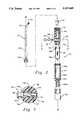
- FIG. 2is an exploded view in longitudinal cross section of the apparatus of FIG. 1;
- FIG. 3is an enlarged side view of a caged tip at the end of the apparatus of FIG. 2;
- FIG. 4is an end view of the caged tip of FIG. 2;
- FIG. 5is an enlarged side view in longitudinal cross section of the apparatus of FIG. 2 in the vicinity of a check valve
- FIG. 6is an end view of the check valve as view from the bottom of FIG. 5;
- FIG. 7is an enlarged cross sectional view of the apparatus taken along the line 7--7 of FIG. 2.
- FIG. 1an aortic sampling apparatus 10 inserted through an arteriotomy a made for arterial perfusion at a site next to the takeoff of the innominate artery b on the ascending aorta.
- the inserted end of the apparatusis shown in solid outline in contact with atherosclerotic deposits c on the inner curvature of the transverse arch of the aorta, and in dotted outline in contact with such deposits d, if any, on the descending aorta distal to the left subclavian artery e.
- apparatus 10includes a probe or cannula 12 having a flanged end 12a threadingly engaging one end of a hollow elongate handle section 14 along a longitudinal axis A--A.
- Thisallows cannula 12 to be removed from handle section 14 for separate sterilizing or disposal of parts.
- the proximal end of cannula 12may be cemented in place to ensure a permanent seal.
- the length and curvature of cannula 12provide for optimum accessibility from the site of the aortic incision to either of the aforesaid aortic areas of plaque buildup.
- a typical cannula configuration for aortic samplinghas an overall length of approximately 165 mm measured from handle section 14.
- the cannulais defined by a straight section 12b elongated along axis an A--A, and a curved section 12c which terminates about 13 mm of axis A--A with a four-strutted cage 12d.
- the cageinsures that the tip of the cannula is free to draw any dislodged plaque quickly into the instrument while preventing large fragments from blocking the cannula passage. It also prevents the opening at the cannula tip from becoming completely blocked by engagement with the interior wall of the aorta.
- the passage of cannula 12communicates with a cylindrical chamber 14a in handle section 14a which contains an elastomeric check valve 16 having a hollow cylindrical section 16a with a flange 16b at the inlet seated on a shoulder 14b at the inlet of chamber 14a.
- the valve outletincludes resilient lips 16c tapering together to a normally closed state to prevent backflow of fluid to the cannula 12. This check valve helps to insure against flow of air into the cannula, which could result in the generation of an air embolism, with possibly disastrous consequences.
- chamber 14areduces to a narrow bore 14d containing a manually operated slide valve 18 in a cross bore 18a.
- a helical spring 20 and O-ring 22cooperate to hold a spindle 18b in a position in which it substantially closes off bore 14d.
- a clearance between bore 18a and spindle 18binsures there will always be a slight amount of flow, further insuring against the passage of air into the blood vessels before the heart pump acts in a vacuum mode.
- valve 18Depressing a knurled end 18c of valve 18 against the force of spring 20 allows fluid to flow freely through passage 14d into a hollow elongated handle section 24 which is threadingly engaged in coaxial alignment with handle section 14 at the end opposite of cannula 12.
- the exteriors of handle sections 14 and 24are uniformly circular in cross-section along their combined length but for oppositely disposed flat sides 14e (FIG. 7) which are normal to the length of valve 18 and provide a positive hand grip surface.
- Trap 26includes a mesh pouch 26a secured around the inlet to a collar 26b which fits snugly on a boss 14f extending beyond the threaded end of section 14 and which seats against a shoulder 24b at the inlet of chamber 24a.
- Pouch 26ais substantially square in cross section but for a portion adjacent collar 26b thus providing clearance adjacent the side of chamber 24a for fluid to flow through the sides as well as through the bottom of pouch 26a.
- Chamber 24narrows into a bore 24c formed in a neck end 24d of section 24.
- a series of concentric ridges about the neckprovide a positive grip and seal for an elastomeric suction tube 30 from the heart-lung machine.
- Handle section 24is preferably fabricated of transparent plastic to enable visual inspection of fluid flowing through the apparatus.
- a method of sampling for aortic plaque with the above-described apparatus according to the invention prior to initiating cardiopulmonary bypass surgeryis as follows. Following exposure of the aorta and the heart for contemplated bypass surgery, a double purse string is placed around the site selected for arterial perfusion, usually next to the takeoff of the innominate artery on the ascending aorta, and an arteriotomy is made within the site area. With valve 18 of sampling apparatus 10 closed but for the slight clearance in cross bore 18a, a perfusion pump operating in the suction mode creates a vacuum in the cannula 12 through check valve 16. Cannula 12 is then inserted and the purse string tightened for hemostasis.
- Samplingstarts by pressing the knurled valve 18 inward to increase suction, preferably at a flow rate of 40 cc/kg/min. or approximately one-half of cardiac output.
- the cage 12dis passed posteriorly along the inner curvature of the aortic arch gently rubbing the wall for about two to three seconds.
- the handle of the instrumentis then rotated to bring the tip of the cannula into engagement with the wall of the descending aorta at a location distal to the left subclavian artery.
- the procedurecontinues for another two to three seconds over the descending aorta an estimated four to six centimeters distal to the left subclavian, bringing the cage 12d toward the left subclavian artery.
- the cageis then pulled off the wall of the descending aorta with suction continuing for another two to three seconds to allow the uptake of any loosened debris.
- the time required to test both areas of the aortais approximately ten seconds.
- Valve 18is then allowed to close while the tip of cannula 12 is still within the descending aorta. After it is removed, pump suction may be stopped and trap 26 removed for inspection of any yellow particulates suggestive of atherosclerosis. If no particulate or only intima is found in the filter, a perfusion cannula may be installed through the same arteriotomy in order to proceed with the bypass surgery.
Landscapes
- Health & Medical Sciences (AREA)
- Surgery (AREA)
- Life Sciences & Earth Sciences (AREA)
- Heart & Thoracic Surgery (AREA)
- Pathology (AREA)
- Radiology & Medical Imaging (AREA)
- Engineering & Computer Science (AREA)
- Biomedical Technology (AREA)
- Nuclear Medicine, Radiotherapy & Molecular Imaging (AREA)
- Medical Informatics (AREA)
- Molecular Biology (AREA)
- Animal Behavior & Ethology (AREA)
- General Health & Medical Sciences (AREA)
- Public Health (AREA)
- Veterinary Medicine (AREA)
- External Artificial Organs (AREA)
Abstract
Description
Claims (13)
Priority Applications (1)
| Application Number | Priority Date | Filing Date | Title |
|---|---|---|---|
| US07/776,825US5197485A (en) | 1991-10-15 | 1991-10-15 | Method and apparatus for sampling aortic plaque |
Applications Claiming Priority (1)
| Application Number | Priority Date | Filing Date | Title |
|---|---|---|---|
| US07/776,825US5197485A (en) | 1991-10-15 | 1991-10-15 | Method and apparatus for sampling aortic plaque |
Publications (1)
| Publication Number | Publication Date |
|---|---|
| US5197485Atrue US5197485A (en) | 1993-03-30 |
Family
ID=25108481
Family Applications (1)
| Application Number | Title | Priority Date | Filing Date |
|---|---|---|---|
| US07/776,825Expired - Fee RelatedUS5197485A (en) | 1991-10-15 | 1991-10-15 | Method and apparatus for sampling aortic plaque |
Country Status (1)
| Country | Link |
|---|---|
| US (1) | US5197485A (en) |
Cited By (41)
| Publication number | Priority date | Publication date | Assignee | Title |
|---|---|---|---|---|
| US5358507A (en)* | 1991-07-26 | 1994-10-25 | Pat O. Daily | Thromboendarterectomy suction dissector |
| US6048331A (en)* | 1996-05-14 | 2000-04-11 | Embol-X, Inc. | Cardioplegia occluder |
| US6231544B1 (en) | 1996-05-14 | 2001-05-15 | Embol-X, Inc. | Cardioplegia balloon cannula |
| US6425883B1 (en) | 1998-05-08 | 2002-07-30 | Circuit Tree Medical, Inc. | Method and apparatus for controlling vacuum as a function of ultrasonic power in an ophthalmic phaco aspirator |
| US6478781B1 (en) | 2000-04-11 | 2002-11-12 | Circuit Tree Medical, Inc. | Anterior chamber stabilizing device for use in eye surgery |
| US20020173812A1 (en)* | 1997-07-24 | 2002-11-21 | Mcguckin James F. | Rotational thrombectomy device |
| US20020177824A1 (en)* | 2000-03-14 | 2002-11-28 | Hajianpour Mohammed Ali | Surgical suction probe system with an easily cleaned internal filter |
| US20030020662A1 (en)* | 2001-04-27 | 2003-01-30 | Brian St. Hillaire | Diversity slot antenna |
| US6602264B1 (en) | 1997-07-24 | 2003-08-05 | Rex Medical, L.P. | Rotational thrombectomy apparatus and method with standing wave |
| US20040097828A1 (en)* | 2002-11-18 | 2004-05-20 | Pellegrino Richard C. | Bone marrow aspiration system |
| US20040220496A1 (en)* | 2002-01-04 | 2004-11-04 | Gonzalez Hugo X. | System and method for capturing body tissue samples |
| US20060264989A1 (en)* | 1999-10-22 | 2006-11-23 | Rex Medical, L.P. | Double balloon thrombectomy catheter |
| US20060270974A1 (en)* | 2005-05-16 | 2006-11-30 | Kerberos Proximal Solutions, Inc. | Methods and systems for filtering aspirated materials |
| US20100312268A1 (en)* | 2006-11-29 | 2010-12-09 | Amir Belson | Embolic protection device |
| US20110040314A1 (en)* | 1999-10-22 | 2011-02-17 | Mcguckin Jr James F | Rotational Thrombectomy Wire With Blocking Device |
| US20110203581A1 (en)* | 2001-10-25 | 2011-08-25 | Spiration, Inc. | Apparatus and method for deployment of a bronchial obstruction device |
| US20120046681A1 (en)* | 2010-08-23 | 2012-02-23 | Seiko Epson Corporation | Liquid injection device and surgical instrument including liquid injection device |
| US8603127B2 (en) | 2002-03-20 | 2013-12-10 | Spiration, Inc. | Removable anchored lung volume reduction devices and methods |
| US8667973B2 (en) | 2003-04-08 | 2014-03-11 | Spiration, Inc. | Bronchoscopic lung volume reduction method |
| US8679149B2 (en) | 2002-08-27 | 2014-03-25 | Emboline, Inc. | Embolic protection device |
| US8795241B2 (en) | 2011-05-13 | 2014-08-05 | Spiration, Inc. | Deployment catheter |
| US8956319B2 (en) | 2002-05-17 | 2015-02-17 | Spiration, Inc. | One-way valve devices for anchored implantation in a lung |
| US8974527B2 (en) | 2003-08-08 | 2015-03-10 | Spiration, Inc. | Bronchoscopic repair of air leaks in a lung |
| US8974484B2 (en) | 2001-09-11 | 2015-03-10 | Spiration, Inc. | Removable lung reduction devices, systems, and methods |
| US9198669B2 (en) | 2006-03-31 | 2015-12-01 | Spiration, Inc. | Articulable anchor |
| US9492265B2 (en) | 2012-01-06 | 2016-11-15 | Emboline, Inc. | Integrated embolic protection devices |
| US11304792B2 (en) | 2019-02-13 | 2022-04-19 | Emboline, Inc. | Catheter with integrated embolic protection device |
| US20220346813A1 (en)* | 2018-01-26 | 2022-11-03 | Inari Medical, Inc. | Single insertion delivery system for treating embolism and associated systems and methods |
| US11554005B2 (en) | 2018-08-13 | 2023-01-17 | Inari Medical, Inc. | System for treating embolism and associated devices and methods |
| US11648028B2 (en) | 2012-11-20 | 2023-05-16 | Inari Medical, Inc. | Methods and apparatus for treating embolism |
| US11697011B2 (en) | 2017-09-06 | 2023-07-11 | Inari Medical, Inc. | Hemostasis valves and methods of use |
| US11806033B2 (en) | 2017-01-10 | 2023-11-07 | Inari Medical, Inc. | Devices and methods for treating vascular occlusion |
| US11832837B2 (en) | 2004-03-25 | 2023-12-05 | Inari Medical, Inc. | Method for treating vascular occlusion |
| US11864779B2 (en) | 2019-10-16 | 2024-01-09 | Inari Medical, Inc. | Systems, devices, and methods for treating vascular occlusions |
| US11918244B2 (en) | 2015-10-23 | 2024-03-05 | Inari Medical, Inc. | Intravascular treatment of vascular occlusion and associated devices, systems, and methods |
| US12171917B1 (en) | 2024-01-08 | 2024-12-24 | Imperative Care, Inc. | Devices for blood capture and reintroduction during aspiration procedure |
| US12263076B2 (en) | 2015-12-29 | 2025-04-01 | Emboline, Inc. | Multi-access intraprocedural embolic protection device |
| US12343028B2 (en) | 2013-10-21 | 2025-07-01 | Inari Medical, Inc. | Methods and apparatus for treating embolism |
| US12343479B2 (en) | 2016-02-24 | 2025-07-01 | Incept, Llc | Neurovascular catheter |
| US12350443B2 (en) | 2019-03-29 | 2025-07-08 | Incept, Llc | Enhanced flexibility neurovascular catheter |
| US12364496B2 (en) | 2022-01-11 | 2025-07-22 | Inari Medical, Inc. | Devices for removing clot material from intravascularly implanted devices, and associated systems and methods |
Citations (22)
| Publication number | Priority date | Publication date | Assignee | Title |
|---|---|---|---|---|
| US3224434A (en)* | 1962-11-06 | 1965-12-21 | Waldemar Medical Res Foundatio | Cell collector |
| US3342175A (en)* | 1964-11-23 | 1967-09-19 | Robert T Bulloch | Cardiac biopsy instrument |
| US3526219A (en)* | 1967-07-21 | 1970-09-01 | Ultrasonic Systems | Method and apparatus for ultrasonically removing tissue from a biological organism |
| DE2043843A1 (en)* | 1970-06-15 | 1972-01-27 | Hyden, Victor Holger, Prof. Dr.med.; Hasselblad, Fritz Victor, Dr.techn.; Göteborg (Schweden) | Device for taking samples from internal human and animal organs |
| US3785380A (en)* | 1972-02-22 | 1974-01-15 | R Brumfield | Filtering blood sucker |
| US3889657A (en)* | 1974-02-12 | 1975-06-17 | Gomco Surgical Mfg Co | Uterine aspirating curette |
| US4243048A (en)* | 1976-09-21 | 1981-01-06 | Jim Zegeer | Biopsy device |
| US4249541A (en)* | 1979-04-26 | 1981-02-10 | David S. Pratt | Biopsy device |
| DE3045245A1 (en)* | 1979-12-03 | 1981-06-19 | Applied Medical Devices, Inc., Westminster, Col. | DEVICE FOR SEPARATING AND ANALYZING BONE MARKER CELLS |
| WO1981003125A1 (en)* | 1980-05-08 | 1981-11-12 | Biomedical Eng Corp | Hand grip operated variable surgical suction apparatus |
| US4393879A (en)* | 1980-04-11 | 1983-07-19 | Milex Products, Inc. | Tissue-collecting apparatus |
| US4655226A (en)* | 1983-12-16 | 1987-04-07 | Southland Instruments, Inc. | Disposable biopsy needle unit |
| US4680029A (en)* | 1984-02-23 | 1987-07-14 | Sherwood Medical Company | Vena caval catheter |
| US4794928A (en)* | 1987-06-10 | 1989-01-03 | Kletschka Harold D | Angioplasty device and method of using the same |
| US4815477A (en)* | 1986-10-15 | 1989-03-28 | The Kendall Company | Urine meter drain container with large and small sample ports |
| US4838855A (en)* | 1987-07-31 | 1989-06-13 | Lynn Lawrence A | Blood aspiration assembly and method |
| US4857045A (en)* | 1987-04-30 | 1989-08-15 | Schneider (Usa) Inc., A Pfizer Company | Atherectomy catheter |
| WO1990001300A1 (en)* | 1988-08-05 | 1990-02-22 | Sonic Needle Corporation | Ultrasonic device for applying cavitation forces |
| US5011490A (en)* | 1989-12-07 | 1991-04-30 | Medical Innovative Technologies R&D Limited Partnership | Endoluminal tissue excision catheter system and method |
| US5030201A (en)* | 1989-11-24 | 1991-07-09 | Aubrey Palestrant | Expandable atherectomy catheter device |
| US5073168A (en)* | 1988-10-05 | 1991-12-17 | Danforth John W | Y-adaptor and percutaneous sheath for intravascular catheters |
| US5087265A (en)* | 1989-02-17 | 1992-02-11 | American Biomed, Inc. | Distal atherectomy catheter |
- 1991
- 1991-10-15USUS07/776,825patent/US5197485A/ennot_activeExpired - Fee Related
Patent Citations (23)
| Publication number | Priority date | Publication date | Assignee | Title |
|---|---|---|---|---|
| US3224434A (en)* | 1962-11-06 | 1965-12-21 | Waldemar Medical Res Foundatio | Cell collector |
| US3342175A (en)* | 1964-11-23 | 1967-09-19 | Robert T Bulloch | Cardiac biopsy instrument |
| US3526219A (en)* | 1967-07-21 | 1970-09-01 | Ultrasonic Systems | Method and apparatus for ultrasonically removing tissue from a biological organism |
| DE2043843A1 (en)* | 1970-06-15 | 1972-01-27 | Hyden, Victor Holger, Prof. Dr.med.; Hasselblad, Fritz Victor, Dr.techn.; Göteborg (Schweden) | Device for taking samples from internal human and animal organs |
| US3727602A (en)* | 1970-06-15 | 1973-04-17 | V Hyden | Instrument for taking samples from internal organs |
| US3785380A (en)* | 1972-02-22 | 1974-01-15 | R Brumfield | Filtering blood sucker |
| US3889657A (en)* | 1974-02-12 | 1975-06-17 | Gomco Surgical Mfg Co | Uterine aspirating curette |
| US4243048A (en)* | 1976-09-21 | 1981-01-06 | Jim Zegeer | Biopsy device |
| US4249541A (en)* | 1979-04-26 | 1981-02-10 | David S. Pratt | Biopsy device |
| DE3045245A1 (en)* | 1979-12-03 | 1981-06-19 | Applied Medical Devices, Inc., Westminster, Col. | DEVICE FOR SEPARATING AND ANALYZING BONE MARKER CELLS |
| US4393879A (en)* | 1980-04-11 | 1983-07-19 | Milex Products, Inc. | Tissue-collecting apparatus |
| WO1981003125A1 (en)* | 1980-05-08 | 1981-11-12 | Biomedical Eng Corp | Hand grip operated variable surgical suction apparatus |
| US4655226A (en)* | 1983-12-16 | 1987-04-07 | Southland Instruments, Inc. | Disposable biopsy needle unit |
| US4680029A (en)* | 1984-02-23 | 1987-07-14 | Sherwood Medical Company | Vena caval catheter |
| US4815477A (en)* | 1986-10-15 | 1989-03-28 | The Kendall Company | Urine meter drain container with large and small sample ports |
| US4857045A (en)* | 1987-04-30 | 1989-08-15 | Schneider (Usa) Inc., A Pfizer Company | Atherectomy catheter |
| US4794928A (en)* | 1987-06-10 | 1989-01-03 | Kletschka Harold D | Angioplasty device and method of using the same |
| US4838855A (en)* | 1987-07-31 | 1989-06-13 | Lynn Lawrence A | Blood aspiration assembly and method |
| WO1990001300A1 (en)* | 1988-08-05 | 1990-02-22 | Sonic Needle Corporation | Ultrasonic device for applying cavitation forces |
| US5073168A (en)* | 1988-10-05 | 1991-12-17 | Danforth John W | Y-adaptor and percutaneous sheath for intravascular catheters |
| US5087265A (en)* | 1989-02-17 | 1992-02-11 | American Biomed, Inc. | Distal atherectomy catheter |
| US5030201A (en)* | 1989-11-24 | 1991-07-09 | Aubrey Palestrant | Expandable atherectomy catheter device |
| US5011490A (en)* | 1989-12-07 | 1991-04-30 | Medical Innovative Technologies R&D Limited Partnership | Endoluminal tissue excision catheter system and method |
Cited By (114)
| Publication number | Priority date | Publication date | Assignee | Title |
|---|---|---|---|---|
| US5522826A (en)* | 1991-07-26 | 1996-06-04 | Daily; Pat O. | Thromboendarterectomy dissector and suction instrument |
| US5358507A (en)* | 1991-07-26 | 1994-10-25 | Pat O. Daily | Thromboendarterectomy suction dissector |
| US6048331A (en)* | 1996-05-14 | 2000-04-11 | Embol-X, Inc. | Cardioplegia occluder |
| US6231544B1 (en) | 1996-05-14 | 2001-05-15 | Embol-X, Inc. | Cardioplegia balloon cannula |
| US20080065008A1 (en)* | 1996-05-14 | 2008-03-13 | Denise Barbut | Aortic occluder with associated filter and methods of use during cardiac surgery |
| US20060074441A1 (en)* | 1997-07-24 | 2006-04-06 | Rex Medical, L.P. | Rotational thrombectomy device |
| US7507246B2 (en) | 1997-07-24 | 2009-03-24 | Rex Medical, L.P. | Rotational thrombectomy device |
| US20020173812A1 (en)* | 1997-07-24 | 2002-11-21 | Mcguckin James F. | Rotational thrombectomy device |
| US7037316B2 (en) | 1997-07-24 | 2006-05-02 | Mcguckin Jr James F | Rotational thrombectomy device |
| US6602264B1 (en) | 1997-07-24 | 2003-08-05 | Rex Medical, L.P. | Rotational thrombectomy apparatus and method with standing wave |
| US6425883B1 (en) | 1998-05-08 | 2002-07-30 | Circuit Tree Medical, Inc. | Method and apparatus for controlling vacuum as a function of ultrasonic power in an ophthalmic phaco aspirator |
| US20110130778A1 (en)* | 1999-10-22 | 2011-06-02 | Hinchliffe Peter W J | Double balloon thrombectomy catheter |
| US20110040314A1 (en)* | 1999-10-22 | 2011-02-17 | Mcguckin Jr James F | Rotational Thrombectomy Wire With Blocking Device |
| US9017294B2 (en) | 1999-10-22 | 2015-04-28 | Rex Medical, L.P. | Rotational thrombectomy wire with blocking device |
| US7645261B2 (en) | 1999-10-22 | 2010-01-12 | Rex Medical, L.P | Double balloon thrombectomy catheter |
| US7909801B2 (en) | 1999-10-22 | 2011-03-22 | Rex Medical, L.P. | Double balloon thrombectomy catheter |
| US8414543B2 (en) | 1999-10-22 | 2013-04-09 | Rex Medical, L.P. | Rotational thrombectomy wire with blocking device |
| US20060264989A1 (en)* | 1999-10-22 | 2006-11-23 | Rex Medical, L.P. | Double balloon thrombectomy catheter |
| US8435218B2 (en) | 1999-10-22 | 2013-05-07 | Rex Medical, L.P. | Double balloon thrombectomy catheter |
| US20020177824A1 (en)* | 2000-03-14 | 2002-11-28 | Hajianpour Mohammed Ali | Surgical suction probe system with an easily cleaned internal filter |
| US6908455B2 (en)* | 2000-03-14 | 2005-06-21 | Mohammed Ali Hajianpour | Surgical suction probe system with an easily cleaned internal filter |
| US6478781B1 (en) | 2000-04-11 | 2002-11-12 | Circuit Tree Medical, Inc. | Anterior chamber stabilizing device for use in eye surgery |
| US20030020662A1 (en)* | 2001-04-27 | 2003-01-30 | Brian St. Hillaire | Diversity slot antenna |
| US8974484B2 (en) | 2001-09-11 | 2015-03-10 | Spiration, Inc. | Removable lung reduction devices, systems, and methods |
| US8986336B2 (en) | 2001-10-25 | 2015-03-24 | Spiration, Inc. | Apparatus and method for deployment of a bronchial obstruction device |
| US20110203581A1 (en)* | 2001-10-25 | 2011-08-25 | Spiration, Inc. | Apparatus and method for deployment of a bronchial obstruction device |
| US7232414B2 (en)* | 2002-01-04 | 2007-06-19 | Spiration, Inc. | System and method for capturing body tissue samples |
| EP1460942A4 (en)* | 2002-01-04 | 2009-05-20 | Spiration Inc | System and method for capturing body tissue samples |
| US20040220496A1 (en)* | 2002-01-04 | 2004-11-04 | Gonzalez Hugo X. | System and method for capturing body tissue samples |
| US8926647B2 (en) | 2002-03-20 | 2015-01-06 | Spiration, Inc. | Removable anchored lung volume reduction devices and methods |
| US8603127B2 (en) | 2002-03-20 | 2013-12-10 | Spiration, Inc. | Removable anchored lung volume reduction devices and methods |
| US8956319B2 (en) | 2002-05-17 | 2015-02-17 | Spiration, Inc. | One-way valve devices for anchored implantation in a lung |
| US8679149B2 (en) | 2002-08-27 | 2014-03-25 | Emboline, Inc. | Embolic protection device |
| US8728114B2 (en) | 2002-08-27 | 2014-05-20 | Emboline, Inc. | Embolic protection device |
| US10736728B2 (en) | 2002-08-27 | 2020-08-11 | Emboline, Inc. | Embolic protection device |
| US10881494B2 (en) | 2002-08-27 | 2021-01-05 | Emboline, Inc. | Embolic protection device |
| US10016267B2 (en) | 2002-08-27 | 2018-07-10 | Emboline, Inc. | Embolic protection device |
| US20050288605A1 (en)* | 2002-11-18 | 2005-12-29 | Pellegrino Richard C | Bone marrow aspiration system |
| US20040097828A1 (en)* | 2002-11-18 | 2004-05-20 | Pellegrino Richard C. | Bone marrow aspiration system |
| US6981948B2 (en)* | 2002-11-18 | 2006-01-03 | Depuy Spine, Inc. | Bone marrow aspiration system |
| US8667973B2 (en) | 2003-04-08 | 2014-03-11 | Spiration, Inc. | Bronchoscopic lung volume reduction method |
| US8974527B2 (en) | 2003-08-08 | 2015-03-10 | Spiration, Inc. | Bronchoscopic repair of air leaks in a lung |
| US9622752B2 (en) | 2003-08-08 | 2017-04-18 | Spiration, Inc. | Bronchoscopic repair of air leaks in a lung |
| US11925369B2 (en) | 2004-03-25 | 2024-03-12 | Inari Medical, Inc. | Method for treating vascular occlusion |
| US11839393B2 (en) | 2004-03-25 | 2023-12-12 | Inari Medical, Inc. | Method for treating vascular occlusion |
| US11832838B2 (en) | 2004-03-25 | 2023-12-05 | Inari Medical, Inc. | Method for treating vascular occlusion |
| US11832837B2 (en) | 2004-03-25 | 2023-12-05 | Inari Medical, Inc. | Method for treating vascular occlusion |
| US11969178B2 (en) | 2004-03-25 | 2024-04-30 | Inari Medical, Inc. | Method for treating vascular occlusion |
| US12023057B2 (en) | 2004-03-25 | 2024-07-02 | Inari Medical, Inc. | Method for treating vascular occlusion |
| US20060270974A1 (en)* | 2005-05-16 | 2006-11-30 | Kerberos Proximal Solutions, Inc. | Methods and systems for filtering aspirated materials |
| WO2006124307A3 (en)* | 2005-05-16 | 2007-11-01 | Fox Hollow Technologies Inc | Methods and systems for filtering aspirated materials |
| US9198669B2 (en) | 2006-03-31 | 2015-12-01 | Spiration, Inc. | Articulable anchor |
| US10617507B2 (en) | 2006-11-29 | 2020-04-14 | Emboline, Inc. | Embolic protection device |
| US20100312268A1 (en)* | 2006-11-29 | 2010-12-09 | Amir Belson | Embolic protection device |
| US9107734B2 (en)* | 2006-11-29 | 2015-08-18 | Emboline, Inc. | Embolic protection device |
| US9770318B2 (en) | 2006-11-29 | 2017-09-26 | Emboline, Inc. | Embolic protection device |
| US10939987B2 (en) | 2006-11-29 | 2021-03-09 | Emboline, Inc. | Embolic protection device |
| US9277934B2 (en)* | 2010-08-23 | 2016-03-08 | Seiko Epson Corporation | Liquid injection device and surgical instrument including liquid injection device |
| US9924957B2 (en) | 2010-08-23 | 2018-03-27 | Argon Medical Devices, Inc. | Rotational thrombectomy wire with blocking device |
| US20120046681A1 (en)* | 2010-08-23 | 2012-02-23 | Seiko Epson Corporation | Liquid injection device and surgical instrument including liquid injection device |
| US8795241B2 (en) | 2011-05-13 | 2014-08-05 | Spiration, Inc. | Deployment catheter |
| US9827085B2 (en) | 2012-01-06 | 2017-11-28 | Emboline, Inc. | Integrated embolic protection devices |
| US12076224B2 (en) | 2012-01-06 | 2024-09-03 | Emboline, Inc. | Integrated embolic protection devices |
| US11051927B2 (en) | 2012-01-06 | 2021-07-06 | Emboline, Inc. | Integrated embolic protection devices |
| US9492265B2 (en) | 2012-01-06 | 2016-11-15 | Emboline, Inc. | Integrated embolic protection devices |
| US10617510B2 (en) | 2012-01-06 | 2020-04-14 | Emboline, Inc. | Introducer sheath with embolic protection |
| US9877821B2 (en) | 2012-01-06 | 2018-01-30 | Emboline, Inc. | Introducer sheath with embolic protection |
| US10166094B2 (en) | 2012-01-06 | 2019-01-01 | Emboline, Inc. | Integrated embolic protection devices |
| US11648028B2 (en) | 2012-11-20 | 2023-05-16 | Inari Medical, Inc. | Methods and apparatus for treating embolism |
| US12343028B2 (en) | 2013-10-21 | 2025-07-01 | Inari Medical, Inc. | Methods and apparatus for treating embolism |
| US11918244B2 (en) | 2015-10-23 | 2024-03-05 | Inari Medical, Inc. | Intravascular treatment of vascular occlusion and associated devices, systems, and methods |
| US12310608B2 (en) | 2015-10-23 | 2025-05-27 | Inari Medical, Inc. | Intravascular treatment of vascular occlusion and associated devices, systems, and methods |
| US11918243B2 (en) | 2015-10-23 | 2024-03-05 | Inari Medical, Inc. | Intravascular treatment of vascular occlusion and associated devices, systems, and methods |
| US12263076B2 (en) | 2015-12-29 | 2025-04-01 | Emboline, Inc. | Multi-access intraprocedural embolic protection device |
| US12295827B2 (en) | 2015-12-29 | 2025-05-13 | Emboline, Inc. | Multi-access intraprocedural embolic protection device |
| US12343479B2 (en) | 2016-02-24 | 2025-07-01 | Incept, Llc | Neurovascular catheter |
| US11806033B2 (en) | 2017-01-10 | 2023-11-07 | Inari Medical, Inc. | Devices and methods for treating vascular occlusion |
| US12251120B2 (en) | 2017-01-10 | 2025-03-18 | Inari Medical, Inc. | Devices and methods for treating vascular occlusion |
| US11697011B2 (en) | 2017-09-06 | 2023-07-11 | Inari Medical, Inc. | Hemostasis valves and methods of use |
| US11697012B2 (en) | 2017-09-06 | 2023-07-11 | Inari Medical, Inc. | Hemostasis valves and methods of use |
| US11844921B2 (en) | 2017-09-06 | 2023-12-19 | Inari Medical, Inc. | Hemostasis valves and methods of use |
| US12109384B2 (en) | 2017-09-06 | 2024-10-08 | Inari Medical, Inc. | Hemostasis valves and methods of use |
| US11865291B2 (en) | 2017-09-06 | 2024-01-09 | Inari Medical, Inc. | Hemostasis valves and methods of use |
| US20230046775A1 (en)* | 2018-01-26 | 2023-02-16 | Inari Medical, Inc. | Single insertion delivery system for treating embolism and associated systems and methods |
| US12016580B2 (en) | 2018-01-26 | 2024-06-25 | Inari Medical, Inc. | Single insertion delivery system for treating embolism and associated systems and methods |
| US12239333B2 (en) | 2018-01-26 | 2025-03-04 | Inari Medical, Inc. | Single insertion delivery system for treating embolism and associated systems and methods |
| US12156669B2 (en) | 2018-01-26 | 2024-12-03 | Inari Medical, Inc. | Single insertion delivery system for treating embolism and associated systems and methods |
| US11849963B2 (en)* | 2018-01-26 | 2023-12-26 | Inari Medical, Inc. | Single insertion delivery system for treating embolism and associated systems and methods |
| US12102343B2 (en)* | 2018-01-26 | 2024-10-01 | Inari Medical, Inc. | Single insertion delivery system for treating embolism and associated systems and methods |
| US20220346813A1 (en)* | 2018-01-26 | 2022-11-03 | Inari Medical, Inc. | Single insertion delivery system for treating embolism and associated systems and methods |
| US20220346814A1 (en)* | 2018-01-26 | 2022-11-03 | Inari Medical, Inc. | Single insertion delivery system for treating embolism and associated systems and methods |
| US11890180B2 (en) | 2018-08-13 | 2024-02-06 | Inari Medical, Inc. | System for treating embolism and associated devices and methods |
| US11969333B2 (en) | 2018-08-13 | 2024-04-30 | Inari Medical, Inc. | System for treating embolism and associated devices and methods |
| US11980537B2 (en) | 2018-08-13 | 2024-05-14 | Inari Medical, Inc. | System for treating embolism and associated devices and methods |
| US11986382B2 (en) | 2018-08-13 | 2024-05-21 | Inari Medical, Inc. | System for treating embolism and associated devices and Methods |
| US11998436B2 (en) | 2018-08-13 | 2024-06-04 | Inari Medical, Inc. | System for treating embolism and associated devices and methods |
| US11974910B2 (en) | 2018-08-13 | 2024-05-07 | Inari Medical, Inc. | System for treating embolism and associated devices and methods |
| US11554005B2 (en) | 2018-08-13 | 2023-01-17 | Inari Medical, Inc. | System for treating embolism and associated devices and methods |
| US11969331B2 (en) | 2018-08-13 | 2024-04-30 | Inari Medical, Inc. | System for treating embolism and associated devices and methods |
| US11969332B2 (en) | 2018-08-13 | 2024-04-30 | Inari Medical, Inc. | System for treating embolism and associated devices and methods |
| US11642209B2 (en) | 2018-08-13 | 2023-05-09 | Inari Medical, Inc. | System for treating embolism and associated devices and methods |
| US11963861B2 (en) | 2018-08-13 | 2024-04-23 | Inari Medical, Inc. | System for treating embolism and associated devices and methods |
| US11974909B2 (en) | 2018-08-13 | 2024-05-07 | Inari Medical, Inc. | System for treating embolism and associated devices and methods |
| US11744691B2 (en) | 2018-08-13 | 2023-09-05 | Inari Medical, Inc. | System for treating embolism and associated devices and methods |
| US11833023B2 (en) | 2018-08-13 | 2023-12-05 | Inari Medical, Inc. | System for treating embolism and associated devices and methods |
| US11559382B2 (en) | 2018-08-13 | 2023-01-24 | Inari Medical, Inc. | System for treating embolism and associated devices and methods |
| US12239523B2 (en) | 2019-02-13 | 2025-03-04 | Emboline, Inc. | Catheter with integrated embolic protection device |
| US11304792B2 (en) | 2019-02-13 | 2022-04-19 | Emboline, Inc. | Catheter with integrated embolic protection device |
| US12350443B2 (en) | 2019-03-29 | 2025-07-08 | Incept, Llc | Enhanced flexibility neurovascular catheter |
| US12274459B2 (en) | 2019-10-16 | 2025-04-15 | Inari Medical, Inc. | Systems, devices, and methods for treating vascular occlusions |
| US11864779B2 (en) | 2019-10-16 | 2024-01-09 | Inari Medical, Inc. | Systems, devices, and methods for treating vascular occlusions |
| US11937834B2 (en) | 2019-10-16 | 2024-03-26 | Inari Medical, Inc. | Systems, devices, and methods for treating vascular occlusions |
| US12364496B2 (en) | 2022-01-11 | 2025-07-22 | Inari Medical, Inc. | Devices for removing clot material from intravascularly implanted devices, and associated systems and methods |
| US12171917B1 (en) | 2024-01-08 | 2024-12-24 | Imperative Care, Inc. | Devices for blood capture and reintroduction during aspiration procedure |
Similar Documents
| Publication | Publication Date | Title |
|---|---|---|
| US5197485A (en) | Method and apparatus for sampling aortic plaque | |
| US5827229A (en) | Percutaneous aspiration thrombectomy catheter system | |
| US6776770B1 (en) | Thromboaspiration valve-filter device and methods | |
| AU2003252147B9 (en) | Blood aspiration system and methods of use | |
| JP2651425B2 (en) | Blood suction assembly | |
| US6719717B1 (en) | Thrombectomy treatment system and method | |
| US2804075A (en) | Non-clogging surgical aspirator | |
| US20230310751A1 (en) | Blood-filtering devices for use with clot treatment systems | |
| US5779649A (en) | Surgical suction wand with filter | |
| US6059745A (en) | Thrombectomy device and associated method | |
| US3955573A (en) | Anticoagulant delivery device and method | |
| US20240173042A1 (en) | Device for clot retrieval with varying tube diameters | |
| JPS63257548A (en) | Surgical suction tip | |
| DE69736565D1 (en) | Shunt for maintaining distal blood flow during arteriotomy surgery | |
| WO1998044982A1 (en) | Percutaneous aspiration catheter system | |
| WO1988000481A1 (en) | Surgical suction device | |
| JP2021527479A (en) | Bone fragment collector and processor | |
| JPH07136244A (en) | Disposable blood cleaning and recovering device | |
| JP2018526046A (en) | System and method for removing fat from collected blood | |
| KR20050013927A (en) | Sheath with air trap | |
| EP3031412B1 (en) | Catheter with a collection chamber | |
| JPH0330773A (en) | Automatic blood-transfusion apparatus | |
| CA1073301A (en) | Anticoagulant delivery device and method | |
| US20250177625A1 (en) | Filtering devices, such as for use with clot treatment systems, and associated systems and methods | |
| US20250222185A1 (en) | Devices for blood capture and reintroduction during aspiration procedure |
Legal Events
| Date | Code | Title | Description |
|---|---|---|---|
| AS | Assignment | Owner name:PILLING CO., A CORP. OF PA, PENNSYLVANIA Free format text:ASSIGNMENT OF ASSIGNORS INTEREST.;ASSIGNOR:GROOTERS, RONALD K.;REEL/FRAME:005895/0657 Effective date:19911007 | |
| CC | Certificate of correction | ||
| FEPP | Fee payment procedure | Free format text:PAT HLDR NO LONGER CLAIMS SMALL ENT STAT AS INDIV INVENTOR (ORIGINAL EVENT CODE: LSM1); ENTITY STATUS OF PATENT OWNER: LARGE ENTITY | |
| AS | Assignment | Owner name:PILLING WECK INCORPORATED, PENNSYLVANIA Free format text:CHANGE OF NAME;ASSIGNOR:PILLING CO.;REEL/FRAME:007786/0129 Effective date:19940520 | |
| FPAY | Fee payment | Year of fee payment:4 | |
| AS | Assignment | Owner name:TECHNOLOGY HOLDING COMPANY II, DELAWARE Free format text:ASSIGNMENT OF ASSIGNORS INTEREST;ASSIGNOR:PILLING WECK INCORPORATED;REEL/FRAME:010255/0973 Effective date:19990715 | |
| REMI | Maintenance fee reminder mailed | ||
| LAPS | Lapse for failure to pay maintenance fees | ||
| FP | Lapsed due to failure to pay maintenance fee | Effective date:20010330 | |
| STCH | Information on status: patent discontinuation | Free format text:PATENT EXPIRED DUE TO NONPAYMENT OF MAINTENANCE FEES UNDER 37 CFR 1.362 |