US5197484A - Method and device for precutaneous excisional breast biopsy - Google Patents
Method and device for precutaneous excisional breast biopsyDownload PDFInfo
- Publication number
- US5197484A US5197484AUS07/880,208US88020892AUS5197484AUS 5197484 AUS5197484 AUS 5197484AUS 88020892 AUS88020892 AUS 88020892AUS 5197484 AUS5197484 AUS 5197484A
- Authority
- US
- United States
- Prior art keywords
- cannula
- driving
- recited
- cutting
- cutting means
- Prior art date
- Legal status (The legal status is an assumption and is not a legal conclusion. Google has not performed a legal analysis and makes no representation as to the accuracy of the status listed.)
- Expired - Lifetime
Links
- 210000000481breastAnatomy0.000titleclaimsabstractdescription87
- 238000000034methodMethods0.000titleclaimsdescription32
- 238000001574biopsyMethods0.000titledescription23
- 238000005520cutting processMethods0.000claimsabstractdescription83
- 230000000149penetrating effectEffects0.000claimsabstractdescription18
- 230000004913activationEffects0.000claimsabstractdescription17
- 230000004807localizationEffects0.000claimsabstractdescription15
- 238000005381potential energyMethods0.000claimsabstractdescription5
- 230000003213activating effectEffects0.000claimsdescription7
- 230000000717retained effectEffects0.000claims1
- 239000011324beadSubstances0.000abstractdescription7
- 230000008602contractionEffects0.000abstractdescription2
- 230000003902lesionEffects0.000description59
- 206010028980NeoplasmDiseases0.000description11
- 230000005856abnormalityEffects0.000description11
- 238000013188needle biopsyMethods0.000description10
- 239000000463materialSubstances0.000description9
- 238000001356surgical procedureMethods0.000description9
- 201000011510cancerDiseases0.000description6
- 230000036210malignancyEffects0.000description6
- 238000009607mammographyMethods0.000description6
- 230000033001locomotionEffects0.000description5
- 239000003550markerSubstances0.000description5
- 238000003745diagnosisMethods0.000description4
- 208000026310Breast neoplasmDiseases0.000description3
- 229910000831SteelInorganic materials0.000description3
- 230000007170pathologyEffects0.000description3
- 229910001220stainless steelInorganic materials0.000description3
- 239000010935stainless steelSubstances0.000description3
- 239000010959steelSubstances0.000description3
- 238000012360testing methodMethods0.000description3
- 238000002560therapeutic procedureMethods0.000description3
- 206010006187Breast cancerDiseases0.000description2
- 230000002962histologic effectEffects0.000description2
- 238000003384imaging methodMethods0.000description2
- 238000003780insertionMethods0.000description2
- 230000037431insertionEffects0.000description2
- 230000003211malignant effectEffects0.000description2
- 238000004519manufacturing processMethods0.000description2
- 230000035515penetrationEffects0.000description2
- 239000004033plasticSubstances0.000description2
- 229920003023plasticPolymers0.000description2
- 238000012552reviewMethods0.000description2
- 230000007480spreadingEffects0.000description2
- 238000003892spreadingMethods0.000description2
- 206010002091AnaesthesiaDiseases0.000description1
- 229910000639Spring steelInorganic materials0.000description1
- 208000002847Surgical WoundDiseases0.000description1
- 230000002159abnormal effectEffects0.000description1
- 230000009471actionEffects0.000description1
- 239000000853adhesiveSubstances0.000description1
- 230000001070adhesive effectEffects0.000description1
- 238000001949anaesthesiaMethods0.000description1
- 230000037005anaesthesiaEffects0.000description1
- 238000004458analytical methodMethods0.000description1
- 238000004873anchoringMethods0.000description1
- 238000010420art techniqueMethods0.000description1
- 230000004323axial lengthEffects0.000description1
- 230000008901benefitEffects0.000description1
- 208000030270breast diseaseDiseases0.000description1
- 230000006835compressionEffects0.000description1
- 238000007906compressionMethods0.000description1
- 238000002591computed tomographyMethods0.000description1
- 230000003247decreasing effectEffects0.000description1
- 238000013461designMethods0.000description1
- 238000002059diagnostic imagingMethods0.000description1
- 201000010099diseaseDiseases0.000description1
- 208000037265diseases, disorders, signs and symptomsDiseases0.000description1
- 238000013399early diagnosisMethods0.000description1
- 238000002594fluoroscopyMethods0.000description1
- 230000006870functionEffects0.000description1
- 238000002695general anesthesiaMethods0.000description1
- 238000002690local anesthesiaMethods0.000description1
- 239000002184metalSubstances0.000description1
- 238000012986modificationMethods0.000description1
- 230000004048modificationEffects0.000description1
- 229920002635polyurethanePolymers0.000description1
- 239000004814polyurethaneSubstances0.000description1
- 238000011084recoveryMethods0.000description1
- 125000006850spacer groupChemical group0.000description1
- 239000010421standard materialSubstances0.000description1
- 239000012780transparent materialSubstances0.000description1
- 238000002604ultrasonographyMethods0.000description1
Images


Classifications
- A—HUMAN NECESSITIES
- A61—MEDICAL OR VETERINARY SCIENCE; HYGIENE
- A61B—DIAGNOSIS; SURGERY; IDENTIFICATION
- A61B10/00—Instruments for taking body samples for diagnostic purposes; Other methods or instruments for diagnosis, e.g. for vaccination diagnosis, sex determination or ovulation-period determination; Throat striking implements
- A61B10/02—Instruments for taking cell samples or for biopsy
- A61B10/0233—Pointed or sharp biopsy instruments
- A61B10/0266—Pointed or sharp biopsy instruments means for severing sample
- A—HUMAN NECESSITIES
- A61—MEDICAL OR VETERINARY SCIENCE; HYGIENE
- A61B—DIAGNOSIS; SURGERY; IDENTIFICATION
- A61B90/00—Instruments, implements or accessories specially adapted for surgery or diagnosis and not covered by any of the groups A61B1/00 - A61B50/00, e.g. for luxation treatment or for protecting wound edges
- A61B90/39—Markers, e.g. radio-opaque or breast lesions markers
- A—HUMAN NECESSITIES
- A61—MEDICAL OR VETERINARY SCIENCE; HYGIENE
- A61B—DIAGNOSIS; SURGERY; IDENTIFICATION
- A61B17/00—Surgical instruments, devices or methods
- A61B17/00234—Surgical instruments, devices or methods for minimally invasive surgery
- A61B2017/00349—Needle-like instruments having hook or barb-like gripping means, e.g. for grasping suture or tissue
- A—HUMAN NECESSITIES
- A61—MEDICAL OR VETERINARY SCIENCE; HYGIENE
- A61B—DIAGNOSIS; SURGERY; IDENTIFICATION
- A61B17/00—Surgical instruments, devices or methods
- A61B2017/00743—Type of operation; Specification of treatment sites
- A61B2017/00796—Breast surgery
- A61B2017/008—Removal of tumors
- A—HUMAN NECESSITIES
- A61—MEDICAL OR VETERINARY SCIENCE; HYGIENE
- A61B—DIAGNOSIS; SURGERY; IDENTIFICATION
- A61B17/00—Surgical instruments, devices or methods
- A61B17/32—Surgical cutting instruments
- A61B17/320016—Endoscopic cutting instruments, e.g. arthroscopes, resectoscopes
- A61B2017/32004—Endoscopic cutting instruments, e.g. arthroscopes, resectoscopes having a laterally movable cutting member at its most distal end which remains within the contours of said end
- A—HUMAN NECESSITIES
- A61—MEDICAL OR VETERINARY SCIENCE; HYGIENE
- A61B—DIAGNOSIS; SURGERY; IDENTIFICATION
- A61B90/00—Instruments, implements or accessories specially adapted for surgery or diagnosis and not covered by any of the groups A61B1/00 - A61B50/00, e.g. for luxation treatment or for protecting wound edges
- A61B90/39—Markers, e.g. radio-opaque or breast lesions markers
- A61B2090/3904—Markers, e.g. radio-opaque or breast lesions markers specially adapted for marking specified tissue
- A61B2090/3908—Soft tissue, e.g. breast tissue
- A—HUMAN NECESSITIES
- A61—MEDICAL OR VETERINARY SCIENCE; HYGIENE
- A61B—DIAGNOSIS; SURGERY; IDENTIFICATION
- A61B90/00—Instruments, implements or accessories specially adapted for surgery or diagnosis and not covered by any of the groups A61B1/00 - A61B50/00, e.g. for luxation treatment or for protecting wound edges
- A61B90/39—Markers, e.g. radio-opaque or breast lesions markers
- A61B2090/3987—Applicators for implanting markers
Definitions
- the present inventionconcerns a method and apparatus for percutaneous excisional breast biopsy and a percutaneous excisional breast biopsy device (PEBB device).
- PEBB devicepercutaneous excisional breast biopsy device
- Mammographyis capable of detecting very small abnormalities, often nonpalpable, within the breast.
- mammographyis usually unable to differentiate between malignant and benign lesions. Thus, the surgeon is confronted with the problem of biopsying these lesions.
- Surgical biopsiesare either incisional (removal of only a part of the tumor) or excisional (removal of the entire gross tumor or lesion). Small lesions with a diameter about 1 cm or less are usually excised completely. Relative to needle biopsy, surgical biopsy has higher patient morbidity and costs.
- a fine needle biopsyinvolves obtaining cytologic material through aspiration by a syringe and a needle. A cytologist will then examine the cytologic material. Core needle biopsy removes a small core of tissue through the use of various needles designed for this purpose (e.g., Travenol Tru-Cut needle). A pathologist will then remove and examine the suspect tissue. With core needle biopsy a definitive diagnosis is possible only if a positive diagnosis of malignancy is made.
- the disadvantage of core needle biopsyis that a negative finding is inconclusive because of the possibility of being a false negative. False negatives may be due to an inadequate sample or to the wrong site being sampled. A negative finding usually requires the performance of an open biopsy. Even a positive finding may require surgical excision if conservation therapy is to be employed.
- the use of needle biopsyis usually restricted to tumors larger than 2 mm in diameter. Needle biopsy of smaller, mobile lesions increases the chances of obtaining a false negative.
- the present inventionovercomes the disadvantages and shortcomings of the prior art and provides a method and device for percutaneous excisional breast biopsy.
- PEBB devicepercutaneous excisional breast biopsy device
- the PEBB deviceincludes: a cannula member having upper proximal and lower distal ends and including a cannula opening at the proximal and distal ends, the cannula has a sharp cutting surface at the distal end; a stylet member having upper proximal and lower distal ends and including a stylet having a pointed distal end capable of spreading tissue, the stylet being slidable in the cannula for simultaneous insertion with the cannula, the stylet having a hollow central shaft capable of receiving a localizing needle; and an additional means of cutting tissue.
- the PEBB deviceincludes: a cannula member having upper proximal and lower distal ends, the cannula has a sharp cutting surface at the distal end; a stylet member or obturator having upper proximal and lower distal ends and a pointed distal end capable of spreading tissue, the stylet being slidable in the cannula for simultaneous insertion with the cannula, the stylet having a hollow central shaft capable of receiving a localizing needle; an additional means of cutting tissue; a localizing needle capable of being received into the stylet, the localizing needle capable of receiving a guide wire; a guide wire capable of being received into the localization needle, the guide wire capable of holding position with respect to surrounding tissue.
- Various types of localizing needles and guide wirescan be used with the PEBB device.
- Another object of the present inventionis to provide a new method to accurately locate and precisely remove a breast lesion through use of the PEBB device.
- a further embodiment of the present inventionfeatures an apparatus for removing suspect breast tissue which comprises a stylet or obturator that has an open forward end (for receiving a guide wire), a rear end and an exterior surface.
- the apparatusalso has a cannula which has an internal cavity defined by an interior surface, an open front end and a rear end.
- the cannulais dimensioned to receive the stylet within its internal cavity.
- the apparatusalso includes driving means for driving the cannula forward of the open forward end of the stylet such that suspect breast tissue is receivable within the forward end portion of the cannula's internal cavity.
- Cutting means for cutting suspect breast tissueis positioned within the internal cavity.
- the driving meansincludes a torsion assembly and a cam member.
- the torsion assemblyis in driving engagement with the cannula and in contact with the cam member.
- the torsion assemblyis preferably supported within a housing.
- the torsion assemblyincludes a driving member and a torsion spring secured at one end to the driving member and at an opposite end to the housing.
- the aforementioned cam memberincludes a cylindrical casing with a cam channel formed therein while the driving member includes cylindrical extension with a drive channel formed therein.
- the torsion assemblyfurther comprises a driving pin which is secured to the cannula, extends through the driving channel and is received within the cam channel.
- the driving meansincludes a spacing cylinder about which the torsion spring is wrapped.
- the spacing cylinderis in sliding contact with the driving member at a first end and in contact with the housing at a second end.
- the spacing cylinderincluding a through-hole through which the stylet extends, and the second end of the stylet is supported by the housing.
- the activation meansincludes a button slidingly supported by the housing and a pin member slidingly supported by the driving member when the pin is in a first position.
- the engagement pinis dimensioned and arranged such that a sliding of the button causes disengagement of the engagement pin with respect to the drive member and a release of potential energy in the torsion spring.
- a cutting means for this embodimentincludes a wire and the cannula includes a circumferential recess formed in the interior surface of said cannula at the forward end of the cannula.
- a longitudinal channelextends rearwardly from the forward end of the cannula and the channel and recess are dimensioned and arranged so as to receive the wire which is looped so as to conform with the circumferential recess in the forward end of the cannula.
- the wirehas a first end fixed to the cannula at a position rearward of the loop and a second end in driving engagement with the driving means such that upon activation of the driving means, the loop of wire is contracted in cutting fashion.
- the driving meansincludes means for rotating the cannula while the cannula is being driven forward of the stylet.
- the styletis designed to include a convergently tapering front end section which slopes inwardly at an angle of 20° to 60° off the center line, and the open front end of the cannula includes a convergently tapering front end section which slopes inwardly at an angle which is essentially equal with the tapered front end of the stylet.
- the interior surface of the cannulais preferably cylindrical in shape with a maximum diameter of 7 to 15 mm.
- the tapered stylet or obturatorthus provides penetrating means for penetrating the breast tissue while the sharp edged cannula provides first cutting means for cutting the breast tissue.
- the first cutting meansis in sliding engagement with the penetrating means.
- the looped wireprovides a second cutting means for cutting breast tissue which is positioned at a forward end of the tissue receiving cavity for implementing a cut essentially transverse to the direction of sliding of the first cutting means.
- This latter embodiment of the present inventionprovides an advantageous method for removing suspect breast tissue which comprises inserting the penetrating member to a position behind a suspect breast tissue region and then activating the driving member so as to drive the first cutting means forward of a forward end of the penetrating member and forward of the suspect breast tissue region.
- the activating of the driving memberfurther resulting in activation of a second cutting means when the first cutting means is driven forward of the suspect breast tissue region such that a removable cut-out core of breast tissue is provided.
- a significant advantage of the present inventionlies in the ability to achieve proper positioning of the cannula with respect to the lesion.
- the PEBB deviceis slid along the previously positioned guide wire and a clamping device maintains the PEBB device in proper position with respect to the guide wire which is made taught by the clamping device.
- the PEBBis placed in its activation position by aligning a suitable marker on the PEBB with a marker on the guide wire. As the amount of forward driving of the cannula and the length between the guide wire marking and the guide wire's internal tip is known, there is assured that the forward end of the cannula will be at the appropriate location past the lesion.
- a mammogramcan be conducted while the PEBB is properly positioned with respect to the guide wire marking so as to confirm that the hook of the guide wire is properly positioned. Once proper positioning of the hook is confirmed, the PEBB can be immediately fired. In this way the chance of having the hook move to a different location between the time of checking the location and actual removal of the lesion is avoided.
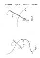
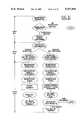
- FIG. 1is a simplified section of a human breast showing a localizing needle which has been passed distal to the breast lesion.
- FIG. 2is a view of the localizing needle through which a hooked guide wire has been passed.
- FIG. 3is a view of the PEBB device which has been placed over the localizing needle and which is entering the breast through a small incision.
- FIG. 4is a view of the PEBB device passing into the breast along the localizing needle and stopping proximate the lesion and the hooked guide wire.
- FIG. 5is a view of the cannula of the PEBB device extended distal to the lesion and the hooked guide wire.
- FIG. 6is a view of the flexible steel cutting edge cutting the tissue distal the lesion and the hooked guide wire.
- FIG. 7is a view of the PEBB device.
- FIG. 8is a view of specially designed hooked guide wire.
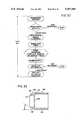
- FIG. 9shows a top planar view of another embodiment of the present invention.
- FIG. 10shows an elevational front view of that which is shown in FIG. 9;
- FIG. 11shows a cross-sectional view taken along cross-section line XI--XI in FIG. 12;
- FIG. 12shows a cross-sectional view taken along cross-section line XII--XII in FIG. 10;
- FIG. 13shows an enlarged view of the circle segment shows in FIG. 12;
- FIG. 14shows a partially broken away, perspective view of the stylet forming part of the present invention
- FIG. 15shows a perspective view of the cannula forming part of the present invention.
- FIG. 16shows a partially cut away, perspective view of the components in FIGS. 14 and 15 in an assembled state
- FIG. 17shows a partially cut away, perspective view of the assembly of FIG. 16 together with a driving member in FIG. 17;
- FIG. 18shows a top planar view of the driving member in FIG. 17.
- FIG. 19shows an elevational rear view of that which is shown in FIG. 18;
- FIG. 20shows a cross-sectional view taken along cross-section line X--X in FIG. 18;
- FIG. 21shows a perspective view of the housing and end plugs which form a part of the present invention.
- FIG. 22shows a perspective view of the cam cylinder which forms a part of the present invention
- FIG. 23shows the opposite side of that which is shown in FIG. 22;
- FIG. 24shows a side elevational view of the frame structure of an alternate embodiment of the cam cylinder
- FIG. 26shows a cam sheet for attachment with the frame structure of FIG. 24;
- FIG. 26Ashows an alternate embodiment of a cam track in which the driving pin follows
- FIG. 26Bshows a cut-away, cross-section of the power spring in FIG. 26A
- FIG. 27shows a top plan view of the alternate embodiment of the cam cylinder
- FIG. 28shows a partially cut away view of the present invention with the alternate embodiment of the cam cylinder in place
- FIG. 28Ashows a view similar to that of FIG. 13 except for the cannula having been driven forward;
- FIG. 29Ashows a cross-sectional and cut away view of one embodiment of the forward end of the stylet
- FIG. 29Bshows an alternate embodiment of that which is shown in FIG. 29A;
- FIG. 30A-30Eshows sequential stages of use of the present invention
- FIG. 31shows a flow chart of the steps involved in a prior art technique
- FIG. 32shows a flow chart of steps included in the present invention.
- FIG. 33shows an enlarged cross-sectional view of the cannula forward end.
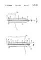
- the PEBB device 1which is preferably rigid.
- the PEBB deviceincludes a cannula 2. Both the distal end 3 and proximate end 4 are open.
- the distal end 3has a sharp cutting surface as at 5.
- the stylet 6corresponds generally in shape to the cannula 2.
- the cylindrical shaft 7 of the stylet 6has a tapered pointed distal puncturing end 8 which terminates in a point 9.
- the stylet or obturator 6has a hollow central shaft 10 through which a localizing needle (not shown) can pass through and out the tapered pointed distal puncturing end 8.
- a descending element 11fits between the cannula 2 and the stylet 6; all three elements fitting together tightly but allowing sufficient room for movement of the three elements.
- Descending element 11optionally has a means at the proximate end for being rotated.
- the distal end 12 of the descending element 11is a flexible steel cutting edge 13.
- the components of the PEBB devicemay be constructed of standard materials commonly used in the manufacture of surgical instruments. For example, stainless steel, polyurethane, suitable plastics of any other suitable surgical material may be employed.
- the PEBB devicemay be of any diameter, preferably 3 mm to 20 mm, and most preferably 10 mm. When plastics are used they can be transparent or opaque, slightly flexible or rigid.
- Localization techniquesare necessary to identify nonpalpable abnormalities before biopsy.
- One techniqueinvolves use of a radiopaque hooked guide wire which has been placed through a localizing needle after the coordinates of the lesion have been determined by mammography.
- Virtually any imaging technique that provides multi-dimensional (e.g., sterotopic), localization of a lesioncan be used to guide a localizing needle (for example, see U.S. Pat. No. 4,784,134).
- imaging techniquesinclude fluoroscopy, ultrasound and computed tomography. Even magnetic resonance can be used with needles made from a special stainless steel. The choice of which modality to use is based on lesion size, position, and visibility; equipment availability; and the skills and preference of the individual radiologist or other trained personnel.
- the hooked guide wire technique for localization of lesionsis well known in the art (Cancer of the Breast, W. L. Donegan and J. S. Spratt, 1988, pages 157-158).
- the localizing needle 20 in FIG. 1is inserted into the breast 31 at the approximate site of the lesion 21 (Breast Diseases, edited by J. R. Harris, S. Hellman, I. C. Henderson, and D. W. Kinne, 1987, pages 82-83).
- the needle tip 22is placed through and distal to the lesion 21, where the term "distal" means a location after the lesion (i.e., under or above, depending on patient position).
- Standard localizing needles of various sizescan be utilized, for example 18 to 28 gauge. The choice of needle type and size depends on the size, type, and location of the lesion and the preference of the radiologist.
- a hooked or anchoring guide wire 23is inserted through the localizing needle 20.
- the hooked guide wire 23has been preloaded into the localizing needle 20 prior to the localizing needle being implanted into the breast.
- the hooked guide wire 23is further inserted through the localizing needle 20 whereupon the hooked end 24 of the hooked guide wire 23 immediately expands.
- the hooked end 24 of the hooked guide wire 23is then lodged at the desired point where it anchors itself in the surrounding breast tissue.
- the hooked end 24 of the hooked guide wire 23provides a relatively stable, anchored guide and serves as a means to locate the lesion 21 when the biopsy takes place. The biopsy may be immediately conducted or it may be conducted at another time or place.
- the hooked guide wire 23may be made of stranded spring steel or any other metal which has a memory (i.e., when the hooked guide wire is place in tissue, and is no longer constrained by the localizing needle, it resumes its original form); it is radiopaque.
- the hooked guide wire 23is resilient in order that it may be compressed and loaded through the localizing needle 20.
- the hooked guide wireis preferably preloaded in the localizing needle prior to biopsy.
- the hooked guide wiremay be of standard length (15-30 cm) and standard size diameter.
- the hooked guide wiremay be of standard design or it may be as hereinafter described.
- the specially designed hooked guide wiremay have 2 to 8 arms (FIG. 8).
- the surgeonmakes a small incision 25 in the breast skin 26 along the implanted localizing needle 20 which contains the hooked guide wire 23.
- the size of the incisionmust be sufficient to allow entry of the PEBB device 1, generally the incision is approximately 7 mm to 20 mm. Local anaesthesia can be utilized.
- the PEBB device 1is passed over the localizing needle 20 and hooked guide wire 23 by inserting the localizing needle 20 and hooked guide wire 23 through the tapered pointed distal puncturing end 8 and hollow central shaft 10 of the stylet 6.
- the tapered pointed distal puncturing end 8 of the stylet or obturatorenters the breast 31 through the incision 25 that has been made.
- the tapered pointed distal puncturing end 8 of the stylet or obturator 6bluntly separates the breast tissue 27.
- the PEBB device 1is advanced towards the lesion 21 and is stopped proximate the lesion 21, where the term "proximate" means a location before the lesion (i.e., under or above, depending on patient position).
- the PEBB devicemay be rotated while it is being advanced.
- the PEBB device 1is generally stopped 1 to 4 cm before the lesion.
- the position of the PEBB device 1is confirmed by mammography.
- the cannula 2 of the PEBB device 1is advanced distal the lesion 21, the sharp cutting device 5 thereby cutting the breast tissue 28 surrounding the lesion 21 as t he cannula 2 is being advanced.
- the cannula 2can be rotated in order to aid cutting.
- a mammogramis conducted to confirm that the lesion is in the chamber 29 formed by the cannula 2.
- the descending element 11is then pushed down in order for the flexible steel cutting edge 13 to internally cut the bottom of the biopsy specimen 30.
- the descending element 11is rotated 360 degrees to completely cut the bottom of the biopsy specimen 30.
- the PEBB device 1is then removed, taking along with it the biopsy specimen 20 in the chamber 29 formed by the cannula 2. Because the tapered pointed distal puncturing end 8 of stylet 6 bluntly separates the breast tissue 27 from incision 25 to lesion 21, this intervening breast tissue 27 is not removed.
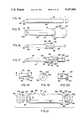
- FIG. 9shows a top planar view of an alternate embodiment 48 of the present invention in position over guide wire 50.
- Guide wire 50includes barb or hook end 52 which is positioned just past the lesion in the same manner previously described.
- PEBB device 48includes cannula 54 which comprises small diameter section 53 having conical forward end 56 which forms a first cutting surface.
- FIG. 9also illustrates stylet or obturator 58 having a tapered puncturing end 60 with opening 62 formed therein. Opening 62 receives guide wire 50 as shown in FIG. 12.
- Cannula 54extends into and is received by housing 64 which has front plug 66, outer casing 70 and back plug 80.
- Fasteners 68, 68' and 82, 82'are used to connect front and back plugs 66 and 80 to outer casing 70 of housing 64.
- FIG. 9also illustrates release button 76 having engagement pin 78 extending therethrough as well as recess 74 formed in casing 70 of housing 64.
- FIG. 9further illustrates guide wire 50 extending out the back end of housing 64 as well as garret wire 88 extending out of the back housing and having stop bead 90 at its rearwardmost end.
- FIG. 10shows a front elevational view of that which shown in FIG. 9 except with guide wire 50 removed.
- fasteners 68, 68'are diametrically opposed while tapered puncturing end 60, tapered front end 56 and the remainder of cannula 54 are concentrically arranged.
- FIG. 12show a cross-sectional view taken along cross-section line XII--XII in FIG. 10.
- FIG. 12illustrates guide wire 50 and barb 52 following passage through lesion 21.
- the forward open end 62 of tapered puncturing end 60is positioned just rearward of lesion 21. As described for the previous embodiment, the forwardmost end of guide wire 60 is placed just forward of lesion 21.
- Guide wire 50passes through open end 62 of cylindrical shaft 59 which forms a part of stylet 58.
- Shaft 59is an elongated member preferably having an outside diameter of 7 mm and a longitudinal length of about 7.5 inches (19.05 cm).
- the tapered puncturing end 60provides 3 to 10 mm of the overall longitudinal length of stylet 58.
- the distance between the tip of guide wire 50 and guide wire marking 51is preferably about 9 to 10 inches (22.86 to 25.40 cm).
- Small diameter section 53 of cannula 54is in the form of an elongated cylinder having an interior surface in sliding engagement with the exterior of cylindrical shaft 59.
- the forwardmost end of smaller diameter section 53includes a forward edge cutting surface 56 which tapers to a sharp edge.
- the forward edge 56 of section 59tapers at an angle similar to the taper of puncturing end 60.
- Cannula 54also includes larger diameter section 55 which is integral with smaller diameter section 53 so as to form step shoulder 61.
- Cannula 54is received within housing 64 such that step shoulder 61 is commensurate with the forwardmost surface of front plug 66.
- Fastener 68 and 68'are illustrated in FIG. 12 as extending through outer casing 70 and cam cylinder 86 so as to fix them in position with respect to front plug 66.
- FIG. 12also illustrates engagement pin 78 extending through release button 76, through block support 98 and into base 93 of driving member 91.
- Driving member 91features cylindrical extension portion 95 which includes longitudinally extending drive channel 92.
- Drive channel 92extends from the forwardmost end of cylindrical extension 91 to a position just forward or commensurate with the forward end of base 93.
- FIG. 12also illustrates driving pin 94 fixedly secured to larger diameter section 55 of cannula 54.
- Driving pin 94extends through drive channel 92 and into cam channel 158 which is described in greater detail below.
- Driving pin 94preferably features hole 96 through which garret wire 88 is threaded.
- base member 93 of driving member 91includes hole 124 through which garret wire 88 is further threaded.
- securement means 101which is preferably in the form of a pin, passes through cylindrical shaft 59 and into spacing cylinder 102.
- Pin member 101can be adhered and/or frictionally wedged in place with respect to corresponding diametrically opposed holes formed in spacing cylinder 102.
- Spacing cylinder 102has a forward end in contact with the rearward end of base member 93 and a rearward end in contact with the forward end of back plate 80.
- spacing cylinder 102In order to allow for rotation of cannula 54, at least one end of spacing cylinder 102 is frictionally contacting and not rigidly secured to the adjacent contacting surface. In a preferred embodiment both ends of spacing cylinder 102 are merely in frictional contact with the adjacent surfaces of base 93 and back plug 80. Low friction coefficient material such as TEFLONTM or the like can be provided at the contacting surfaces so as to facilitate rotation of driving member 91.
- Back plug 80further includes threaded recesses that are sized to receive fasteners 82, 82' which secure the rear end of outer casing 70 to back plug 80.
- back plug 80includes a hole through which the rear end of garret 88 is threaded. This hole is sufficiently large enough so as to enable garret wire 88 to slide therein but sufficiently small enough to prevent bead 90 from passing therethrough.
- Torsion spring 130is shown encircling spacing cylinder 102 and has its forward end secured to the rearward end of base member 93 and its rearward end secured to the forward end of back plug 80.
- FIG. 12also illustrates guide wire marker 51 formed on guide wire 50 and shown in FIG. 12 to be commensurate with the rearward end of back plug 80.
- Guide wire marker 51can take any form but preferably is a painted circle or a spot provided a predetermined distance from the forwardmost end of guide wire 50 for reasons to be explained in greater detail below.
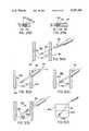
- FIG. 11illustrates a cross-sectional view taken along cross-section line XI--XI in FIG. 12.
- release button 76bridges aperture 72 and has a forward end in sliding contact with a forward section of recess 74 and a rearward end in sliding contact with a rearward section of recess 74.
- Sliding block 98is designed to slide along notch planar surface 100 formed in base member 93.
- Notch planar surface 100 of base member 93also includes an engagement pin notch 122 which extends rearwardly and opens out to the back end of base member 93. (See FIGS. 17-19).
- FIG. 13illustrates an enlarged view of the circled region of FIG. 12 at the forward end of cannula 54.
- the forwardmost end of guide wire 50is positioned forward of the forwardmost end of breast abnormality or lesion 21.
- Barb 52acts to fix guide wire 50 in position with respect to abnormality 21.
- Guide wire 50extends through opening 62 formed at the forwardmost end of tapered protruding end 60 of stylet 58.
- Cannula 54features outer shell 120 and inner cylindrical member 110 securely fixed to shell 120.
- Inner cylindrical member 110includes step shoulder 112 at its forward end and forwardly extending flange 113.
- Inner cylindrical memberfurther includes longitudinal channel 116 within which extends garret wire 88.
- Cap 108is securely fixed between outer cover 120 and inner cylindrical member 110.
- Cap 108includes cap extension 114 which contacts step shoulder 112 so as to form cylindrical recess 106 between the forwardmost end of inner cylindrical member 110 and an internal surface of cap 108.
- Cap member 108, outer shell 120 and inner member 110are preferably adhered or otherwise secured together to form a single unit.
- Cap member 108is further illustrated in FIG. 33. As shown in FIG. 33, channel member 116' is formed therein so as to coincide with channel 116 formed in inner cylindrical member 110.
- Cap member 108includes cut away section 118 which extends from channel 116' to circular recess 106. Recess 106 provides a location for positioning of garret loop 104 shown in FIG. 13 and in greater detail in FIG. 28A.
- Cap 108includes forward edge cutting surface 56 which is defined by tapered surface 119 and internal wall 117 shown in FIG. 33.
- FIG. 33also shows tapered surface 119 forming angle Z with respect to the horizontal.
- angle Zis about 20 to 60 degrees and more preferably 20 degrees.
- FIG. 14shows the stylet 58 alone with its tapering end 60 and opening 62.
- tapering end 60is formed as a continuous portion of cylindrical shaft 59 and preferably tapers either in a continuous manner or in a curved manner so as to form a horn shape.
- FIGS. 29A and 29Billustrate alternate embodiments of the present invention wherein plugs 172 and 172' are provided at the forward end of the cylindrical shaft 59.
- plug 172includes a recess shoulder which receives the forward end of shaft 59 and is preferably adhered or otherwise fixed thereto.
- Plug 172includes a forward penetrating surface 174 which preferably forms angle X with respect to the horizontal.
- Angle Xpreferably has the same dimensions as those of the unitary embodiment noted above (i.e., 20 to 60 degrees). In FIG. 29A, angle X is about 20 degrees. Plug 172 also include interior throughhole 178 which helps in the guiding of PEBB 41 along guide wire 50 (or along a localization needle if the needle is to be maintained in place during operation of the PEBB).
- FIG. 29Billustrates a similar arrangement as that of FIG. 29A except for forward penetrating surface 174' being less inclined than its counterpart in FIG. 29A. As shown in FIG. 29B, angle Y is about 60 degrees with respect to the horizontal.
- FIG. 15illustrates cannula 54 having smaller diameter section 53 and larger diameter section 55.
- Step shoulder 61illustrates the differences in diameter between smaller diameter section 53 and larger diameter section 55, which can either be formed as separate members or more preferably as a single unitary body.
- FIG. 15further illustrates forward cutting surface 56 forming part of cap 108.
- Interior surface 117 as well as the interior surface of inner member 110 (FIG. 13)is designed to slidingly receive the exterior of cylindrical shaft 59 of stylet 58.
- Driving pin 94is shown extending off from larger diameter section 55 and threading hole 96 formed in driving pin 9 is also illustrated in FIG. 15.
- the driving pinworks in conjunction with cam 86 and driving member 91 to provide driving means for driving cannula 54 forward with respect to stylet 58 which is maintained axially stationary by pin 101 (FIG. 12).
- FIG. 16shows the positioning of cannula 54 with respect to stylet 58.
- the frictional contact between cannula 54 and stylet 58is sufficient to provide some degree of positioning ability such that the two members do not slide too easily during assembly.
- Cannula 54is shown in FIG. 16 in its proper position, wherein the forwardmost end of cap 108 is aligned with the origin of tapering end 60 of stylet 58.
- FIGS. 18-20illustrate driving member 91 of the present invention.
- FIG. 18shows a top planar view of driving member 91 which includes base 93 having upper notch section 100 and engagement pin notch 122. Extending forwardly off the forward end of base member 93 is cylindrical extension portion 95. Cylindrical extension portion 95 includes driving channel 92 which extends longitudinally from the forward end of base member 93 to the forwardmost end of extension member 95. Driving channel 92 is sized so as to slidingly receive driving pin 94.
- Driving member 91includes a central aperture 126 which is sized so as to frictionally receive cylindrical shaft 59 and thus the aperture has a diameter essentially equal to the inside diameter of inner member 110 and the inside diameter of cylindrical shaft 102. As shown in FIG.
- back plug 80also includes a central aperture which is similarly sized so as to snugly receive shaft 59.
- Interior wall 12 of driving member 91defines a larger diameter than the diameter defined by aperture 126 and receives the exterior surface of the cannula's larger diametered section 55 in sliding fashion.
- FIG. 17illustrates the positioning of driving member 91 onto the exterior surface of larger diametered section 55 as well as the positioning of driving pin 94 within driving channel 92.
- FIG. 17also provides a partially cut away view of stylet 58 surrounded by spacing cylinder 102 which, in turn, is surrounded by torsion spring 130.
- Torsion spring 130is shown in FIG. 17 to be in the form of a helical type spring. Various other torsion springs can also be relied upon or alternately, a power spring can be used as explained in greater detail below.
- FIG. 21illustrates the preassembled state of housing 64 together with cam cylinder 86 in position.
- front plug 66includes exterior flange 132 and interior member 134 having threaded hole 136 formed therein.
- Interior member 134is designed to fit within the interior surface of cam cylinder 86 which is frictionally received by the interior surface of outer casing 70.
- Outer casing 70includes threaded hole 138 and cam cylinder 86 includes threaded hole 139 (see FIG. 22) which can be aligned together with threaded hole 136 so as to receive fastener 68 (FIG. 12).
- Corresponding threaded holesare formed diametrically opposed to thread holes 136, 138 and 139 so as to receive fastener 68'.
- the rear end of outer casing 70includes threaded hole 140 and a corresponding threaded hole 148 is formed in back plug 80.
- Back plug 80includes exterior flange 142 and interior member 144.
- Interior member 144includes a central aperture 146 which receives the rear end of stylet 58.
- Interior member 144can also optionally include garret wire hole 150.
- Torsion spring securement means 152is shown in FIG. 21 fixed to interior member 144.
- the exterior diameter of interior member 144is dimensioned so as to frictionally contact the interior surface of outer casing 70. The securement of fasteners 82 and 82' results in back plug 80 being fixedly secured to the rear end of outer casing 80.
- the forwardmost surface 155 of inner member 144is positioned such that the rearward end of spacing cylinder 102 is frictionally engaged therewith. Similarly, the forward end of spacing cylinder 102 is frictionally engaged with the rearward end of base member 93.
- Back plug 80could also be threadably engaged with casing 70.
- FIGS. 22 and 23provide two different views of one embodiment of cam cylinder 86.
- Cam cylinder 86includes front end 154 and rear end 156 as well as cam channel 158.
- Cam channel 158includes a forward curve portion 160 which leads to partial circumferential section 162 of cam channel 158. The curved portion provides for a 120° or more rotation of the cutting cannula.
- Section 162 of cam channel 158ends at 164 to provide a stop for driving pin 94.
- FIGS. 24-27illustrate an alternate embodiment (86') of the cam cylinder.
- cam cylinder 86'features a partially cylindrical frame structure 166.
- FIG. 26illustrates flexible material sheet 168 which is dimensioned such that when wrapped within the interior of frame structure 166 it forms cam channel 170 in the manner shown in FIG. 27.
- the driving pincan be dimensioned so as to slide within cam channel 170 and upon reaching the end of cam channel 170 slide along the interior surface of frame structure 166.
- FIG. 28illustrates a partially cut away, top planar view of an alternate embodiment of the present invention which includes modified cam cylinder 86'.
- garret wire 88includes a first end 188 which is secured to the exterior of interior member 110 (or is received within an aperture formed therein).
- Adhesive area 184represents one manner of securing first end 188.
- Garret wire 88extends from its secured end 188 to hole 186 defined by slot 118 (see FIG. 28A). The garret wire is then looped within recess 106 and extended back through hole 186 and along channel 116 through larger diameter section 55 via hole 103 (FIG. 15).
- Garret wire 88extends out of larger diameter section 55 into driving channel 92 and through hole 96 formed in pin 94 as shown in FIGS. 12 and 28. Garret wire 88 then passes through base member 93 and into the open chamber formed at the rear end of casing 70 as shown in FIG. 28 or, alternatively, extends completely through the rear chamber formed in the rear end of casing 70 and through back plug 80 as shown in FIG. 12. As shown in FIG. 28 temporary securement patch 90' formed of wax or the like can be applied to housing 70 to hold wire 88 in position until PEBB 4 is activated.
- FIG. 26Ashows an alternate embodiment of the cam cylinder which is designated 86'' in the figure.
- cam cylinder 86''includes a cam channel (an acme thread groove in this case) in which driving pin 94' travels.
- This arrangementallows for an increase in the number of turns and garret wire take up for a given axial length of the cam cylinder 84''. With this arrangement four complete turns of the cannula are possible for achieving the cutting action.
- the pin and cam cylinderare arranged so that after the end of four turns within the cam channel the driving pin rotates freely for at least one more turn against the edge of the cam cylinder so as to take up the garret loop.
- Driving member 91'includes a spring attachment section 306 which is dimensioned such that power spring 130' coils around it.
- FIG. 26Bshows the coiled nature of power spring 130' secured to attachment section 306 at one end and fixed housing 70 at the other end. Section 306 also takes the place of the previously described spacer.
- Power spring 130'has one end secured to the fixed interior of the housing with fasteners 300 and its other end fixed to rotatable driving member 91' with fasteners 306. Power spring 130' can be coiled prior to fastening the back plug and maintained in place with the engagement pin. The engagement pin is then released such that spring 130' uncoils to provide at least 5 lbf is provided at or near the end of travel for drive pin 94' to ensure that the garret loop achieves its cutting function.
- FIG. 28Aillustrates the final position of cutting surface 108 following activation of the PEBB device at a point just prior to garret loop 104 being made taught in the manner described in greater detail below.
- garret loop 104is positioned sufficiently forward of tip 52 of wire 50 to avoid entanglement during contraction of the loop.
- the material forming the entire cannula 54(or at least the end region of the cannula) is formed of a radiographic transparent material. In this way, a radiographic check can be made to ensure that the forward end of the cutting cannula is sufficiently forward of the guide wire anchors such that the entire guide wire will be removed when the core sample is removed.
- FIGS. 30A to 30Eillustrate the present invention's sequential steps when using PEBB device 48.
- the free end of guide wire 50is threaded through PEBB device 48 in the manner illustrated in FIG. 30A.
- FIG. 30Aillustrates guide wire 50 after having been placed in proper position and verified as being in the proper location in the manner previously described.
- FIG. 30Afurther illustrates breast 190 in a compressed state between film plane 192 and compression panel 194 in the manner well known in the art.
- PEBB device 48is guided along guide wire 50 until the rear end of PEBB device 48 is commensurate with marking 51 formed on guide wire 50 in the manner illustrated in FIG. 30B. As shown in FIG.
- tapered stylet 58 and cannula 54penetrate the breast (preferably following a small incision being made to lessen skin surface tension). The degree of penetration will vary depending upon the location of the lesion within the breast. In any event, once marker 51 is matched with the corresponding reference point on PEBB 48, the distance from tip 52 of wire 50 to the forward end of stylet 58 is a known value.
- PEBB 48can be clamped into position with respect to guide wire 50 by use of clamp 84' (FIG. 9) which can take any form such as those presently used to maintain the guide wire in position with respect to the exterior of the breast.
- Torsion spring 130is preset to a degree of torsion based on the amount of twisting involved in lining up back plug 80 (which is attached to the rear end of torsion spring 130) and fasteners 82 and 82'. Once released from its pre-torsion state, the potential energy in torsion spring 130 is released in a manner which causes driving member 91 to rotate.
- driving member 91causes driving pin 94 and attached cannula 54 to move forward and in a spiral fashion with respect to stylet 58 while driving pin 94 (or 94') follows or moves within cam channel 158 (or within the grooves provided in cam cylinder 86' or 86'') and driving channel 92.
- cannula 54is both driven forward and rotated.
- Cannula 54thus drives through the breast so as to pass by lesion 21 as well as the barbed end of guide wire 52.
- the final positioningis illustrated in FIG. 28A.
- the length from the tip of the hook to the guide wire markingis known and the length of the extension of the cannula from its pre-activation state to its post-activation state is known, precise positioning of the forward edge of the cannula is possible. The precise positioning only requires that garret loop 104 be placed forward of the forward tip of guide wire 50.
- a mammogram check prior to activation and while the PEBB is in position on the guide wireis possible so as to avoid the prior art difficulty of having the hook float or move to a different position within the period between the mammogram check and the placement of the patient at the surgical location.
- Clamps such as claim 84 in FIG. 9which were used in the prior art in an attempt to lock the guide wire in position during movement of the patient during surgery, can also be used in the present invention either on the breast surface or as part of the PEBB to maintain the guide wire taught and at the guide wire mark location.
- loop 104results in a core sample of breast material being formed which has a longitudinal length extending from the cutting location of garret loop 104 to the forward surface of penetrating end 60 and a circumference defined by the interior surface of cylindrical member 110 extending between loop 104 and end surface 60.
- the interior diameter of interior member 110is about 5 to 15 mm and more preferably 7 mm.
- the longitudinal distance between the forwardmost tip 62 of stylet 58 and the cutting location of garret loop 104 (following activation of PEBB 48)is preferably 3 or more mm and more preferably about 3 mm.
- Garret 50is preferably formed of stainless steel and has a diameter of 0.005 inch to 0.008 inch.
- garret loop 104cuts through the tissue at the time cannula 54 reaches its forwardmost position is provided by marking 51 on guide wire 50 which positions the cannula 54 prior to release of lever 76 in just the right location with respect to the lesion.
- garret wire 88is of a length which is sufficient to enable driving pin 94 to reach the end of the curved portion of cam channel at a time when stop bead 90 is placed in an abutting position while the continued release of torsion spring causes loop 104 to be taken up so as to cut through the breast material forward of the lesion.
- FIG. 30Cillustrates cannula 54 in the position shown in greater detail in FIG. 28A.
- PEBB device 48 of the present inventioncan be either hand held by gripping casing 70 or, alternatively, casing 70 can be positioned in a supporting holder (not shown).
- a suitable holdercould be one that is fashioned somewhat like the holder and patient positioning system used with biopsy needle operations (e.g., the MAMMOTESTTM system of Medical Imaging Systems of Hanover, Md.).
- the support means of the standwould be modified to support the PEBB rather than the biopsy needle assembly.
- FIG. 30Dillustrates the drawing out of cannula 54 from breast 190.
- the drawing out of cannula 54results in core 198 being removed from breast 190 but, since stylet 58 was the forwardmost member during initial positioning of PEBB 48, no further breast material is removed and the original passageway closes up forward of cannula 54 as it is being withdrawn from breast 190.
- the core specimen 202 removed from breast 190can then be ejected from PEBB 48 by rotation of cannula 54 and the forcing of cannula 54 rearward until stylet 58 achieves its original position.
- the entire PEBB devicecan then be withdrawn along guide wire 50 leaving core sample 202 in a preserving solution 204 such as contained in sample container 206 as shown in FIG. 30E.
- FIG. 31provides a flow-chart illustration of the sequential steps involved in a breast biopsy procedure utilizing the technique of the prior art.
- a patient in her first visithas a mammogram conducted and a review of the mammogram results are made. If the review of the mammogram shows that no abnormalities exist, that is the end of the procedure. If, however, an abnormality is spotted, a needle biopsy is conducted either during this first visit or at a subsequently scheduled visit.
- the patientis subject to a mastectomy procedure or a lumpectomy proceeding in a third visit.
- a mammogramis conducted followed by a localization procedure (localization needle and guide wire placement), a mammogram check and the removal of the localization needle.
- the tumor and guide wireare later removed in a surgical procedure. The patient is then released following recovery and scheduled for follow-up therapy.
- the patientIn the mastectomy procedure, the patient is subjected to the same procedure as for the lumpectomy except that the major surgery is much more extensive so as to typically require an extended hospital stay.
- FIG. 32illustrates the procedure utilizing the present invention when the abnormality region is contained within a tissue area which is essentially 5 mm in diameter.
- the cannulacan be transparent to the mammography device to facilitate guide wire viewing ability.
- the sample takenis then studied or forward to a pathologist. If the sample taken contains all the abnormalities (which would be true for abnormality regions having the size described above), whether the results are positive or negative would not be of great concern as the potential problem area has been completely removed such that surgery is no longer required. In any event, a malignancy determination by the pathologist would involve the scheduling of a follow-up procedure to monitor the situation. If non-malignant tissue is found, then the procedure is completed.
- the present inventionprovides a procedure which can be completed by a single visit (followed by a subsequent telephone call or letter if the pathology test is not conducted at the same time as the visit) as opposed to the three or four visits required in the prior art procedure.
Landscapes
- Health & Medical Sciences (AREA)
- Life Sciences & Earth Sciences (AREA)
- Surgery (AREA)
- Heart & Thoracic Surgery (AREA)
- Pathology (AREA)
- Engineering & Computer Science (AREA)
- Biomedical Technology (AREA)
- Medical Informatics (AREA)
- Molecular Biology (AREA)
- Animal Behavior & Ethology (AREA)
- General Health & Medical Sciences (AREA)
- Public Health (AREA)
- Veterinary Medicine (AREA)
- Oral & Maxillofacial Surgery (AREA)
- Nuclear Medicine, Radiotherapy & Molecular Imaging (AREA)
- Surgical Instruments (AREA)
Abstract
Description
Claims (25)
Priority Applications (2)
| Application Number | Priority Date | Filing Date | Title |
|---|---|---|---|
| US07/880,208US5197484A (en) | 1990-09-18 | 1992-05-08 | Method and device for precutaneous excisional breast biopsy |
| US08/033,785US5353804A (en) | 1990-09-18 | 1993-03-17 | Method and device for percutaneous exisional breast biopsy |
Applications Claiming Priority (2)
| Application Number | Priority Date | Filing Date | Title |
|---|---|---|---|
| US07/584,614US5111828A (en) | 1990-09-18 | 1990-09-18 | Device for percutaneous excisional breast biopsy |
| US07/880,208US5197484A (en) | 1990-09-18 | 1992-05-08 | Method and device for precutaneous excisional breast biopsy |
Related Parent Applications (1)
| Application Number | Title | Priority Date | Filing Date |
|---|---|---|---|
| US07/584,614Continuation-In-PartUS5111828A (en) | 1990-09-18 | 1990-09-18 | Device for percutaneous excisional breast biopsy |
Related Child Applications (1)
| Application Number | Title | Priority Date | Filing Date |
|---|---|---|---|
| US08/033,785ContinuationUS5353804A (en) | 1990-09-18 | 1993-03-17 | Method and device for percutaneous exisional breast biopsy |
Publications (1)
| Publication Number | Publication Date |
|---|---|
| US5197484Atrue US5197484A (en) | 1993-03-30 |
Family
ID=24338099
Family Applications (2)
| Application Number | Title | Priority Date | Filing Date |
|---|---|---|---|
| US07/584,614Expired - LifetimeUS5111828A (en) | 1990-09-18 | 1990-09-18 | Device for percutaneous excisional breast biopsy |
| US07/880,208Expired - LifetimeUS5197484A (en) | 1990-09-18 | 1992-05-08 | Method and device for precutaneous excisional breast biopsy |
Family Applications Before (1)
| Application Number | Title | Priority Date | Filing Date |
|---|---|---|---|
| US07/584,614Expired - LifetimeUS5111828A (en) | 1990-09-18 | 1990-09-18 | Device for percutaneous excisional breast biopsy |
Country Status (1)
| Country | Link |
|---|---|
| US (2) | US5111828A (en) |
Cited By (111)
| Publication number | Priority date | Publication date | Assignee | Title |
|---|---|---|---|---|
| US5353804A (en)* | 1990-09-18 | 1994-10-11 | Peb Biopsy Corporation | Method and device for percutaneous exisional breast biopsy |
| US5471992A (en)* | 1994-02-08 | 1995-12-05 | Boston Scientific Corporation | Multi-motion cutter multiple biopsy sampling device |
| US5526822A (en)* | 1994-03-24 | 1996-06-18 | Biopsys Medical, Inc. | Method and apparatus for automated biopsy and collection of soft tissue |
| US5573008A (en)* | 1993-10-29 | 1996-11-12 | Boston Scientific Corporation | Multiple biopsy sampling coring device |
| US5601585A (en)* | 1994-02-08 | 1997-02-11 | Boston Scientific Corporation | Multi-motion side-cutting biopsy sampling device |
| US5627907A (en)* | 1994-12-01 | 1997-05-06 | University Of Pittsburgh | Computerized detection of masses and microcalcifications in digital mammograms |
| US5649547A (en)* | 1994-03-24 | 1997-07-22 | Biopsys Medical, Inc. | Methods and devices for automated biopsy and collection of soft tissue |
| US5709697A (en)* | 1995-11-22 | 1998-01-20 | United States Surgical Corporation | Apparatus and method for removing tissue |
| US5782775A (en)* | 1995-10-20 | 1998-07-21 | United States Surgical Corporation | Apparatus and method for localizing and removing tissue |
| EP0720442A4 (en)* | 1993-09-20 | 1998-08-05 | Boston Scient Corp | Multiple biopsy sampling coring device |
| US5800445A (en)* | 1995-10-20 | 1998-09-01 | United States Surgical Corporation | Tissue tagging device |
| US5817034A (en)* | 1995-09-08 | 1998-10-06 | United States Surgical Corporation | Apparatus and method for removing tissue |
| US5848978A (en)* | 1995-11-14 | 1998-12-15 | Genx International, Inc. | Surgical biopsy device |
| US5857982A (en)* | 1995-09-08 | 1999-01-12 | United States Surgical Corporation | Apparatus and method for removing tissue |
| US5871453A (en)* | 1994-02-08 | 1999-02-16 | Boston Scientific Corporation | Moveable sample tube multiple biopsy sampling device |
| US5879357A (en)* | 1995-10-20 | 1999-03-09 | United States Surgical Corporation | Apparatus for marking tissue location |
| US5916229A (en)* | 1996-02-07 | 1999-06-29 | Evans; Donald | Rotating needle biopsy device and method |
| US6007497A (en)* | 1998-06-30 | 1999-12-28 | Ethicon Endo-Surgery, Inc. | Surgical biopsy device |
| US6017316A (en)* | 1997-06-18 | 2000-01-25 | Biopsys Medical | Vacuum control system and method for automated biopsy device |
| WO2000009005A1 (en)* | 1996-07-26 | 2000-02-24 | Russin Lincoln D | Method and apparati for coaxial breast biopsy |
| WO2000012010A1 (en) | 1998-09-01 | 2000-03-09 | Vivant Medical, Inc. | Percutaneous tissue removal device |
| US6048321A (en)* | 1997-10-10 | 2000-04-11 | William E. McPherson | Guide assembly for a biopsy device |
| WO2000024320A1 (en)* | 1998-10-23 | 2000-05-04 | United States Surgical Corporation | Site marker device |
| US6067372A (en)* | 1996-02-22 | 2000-05-23 | University Of Pittsburgh | Method and system to enhance robust identification of abnormal regions in radiographs |
| US6080113A (en)* | 1998-09-11 | 2000-06-27 | Imagyn Medical Technologies California, Inc. | Incisional breast biopsy device |
| US6083237A (en)* | 1998-10-23 | 2000-07-04 | Ethico Endo-Surgery, Inc. | Biopsy instrument with tissue penetrating spiral |
| US6142957A (en)* | 1993-09-20 | 2000-11-07 | Boston Scientific Corporation | Multiple biopsy sampling device |
| US6142955A (en) | 1997-09-19 | 2000-11-07 | United States Surgical Corporation | Biopsy apparatus and method |
| US6238355B1 (en)* | 1998-02-16 | 2001-05-29 | Daum Gmbh | Tumortherapy device and method |
| US6277083B1 (en) | 1999-12-27 | 2001-08-21 | Neothermia Corporation | Minimally invasive intact recovery of tissue |
| US20010047183A1 (en)* | 2000-04-05 | 2001-11-29 | Salvatore Privitera | Surgical device for the collection of soft tissue |
| US20020035324A1 (en)* | 1998-12-24 | 2002-03-21 | Sirimanne D. Laksen | Subcutaneous cavity marking device and method |
| US6383145B1 (en) | 1997-09-12 | 2002-05-07 | Imagyn Medical Technologies California, Inc. | Incisional breast biopsy device |
| US6436054B1 (en) | 1998-11-25 | 2002-08-20 | United States Surgical Corporation | Biopsy system |
| US6471659B2 (en) | 1999-12-27 | 2002-10-29 | Neothermia Corporation | Minimally invasive intact recovery of tissue |
| US6471709B1 (en) | 1998-10-30 | 2002-10-29 | Vivant Medical, Inc. | Expandable ring percutaneous tissue removal device |
| US20030018281A1 (en)* | 2001-07-19 | 2003-01-23 | Huitema Thomas W. | Surgical biopsy device having a flexible cutter |
| US6551253B2 (en) | 1997-09-12 | 2003-04-22 | Imagyn Medical Technologies | Incisional breast biopsy device |
| US20030082797A1 (en)* | 1999-12-17 | 2003-05-01 | Michel Rastorgoueff | Device and method for taking biological sample |
| US6569176B2 (en) | 1999-10-18 | 2003-05-27 | Jerry M. Jesseph | Device and method for improved diagnosis and treatment of cancer |
| US6572563B2 (en)* | 1999-12-22 | 2003-06-03 | Pentax Corporation | Endoscopic tissue collecting instrument |
| US6605047B2 (en) | 2001-09-10 | 2003-08-12 | Vivant Medical, Inc. | Biopsy marker delivery system |
| US20030216667A1 (en)* | 2000-09-11 | 2003-11-20 | Frank Viola | Biopsy system |
| US6656192B2 (en) | 1998-09-25 | 2003-12-02 | United States Surgical Corporatioin | Site marker device |
| US20040044311A1 (en)* | 1998-10-23 | 2004-03-04 | Felix Espositio | Site marker device |
| US6743228B2 (en) | 2001-09-12 | 2004-06-01 | Manoa Medical, Inc. | Devices and methods for tissue severing and removal |
| US20040162574A1 (en)* | 2001-08-03 | 2004-08-19 | Viola Frank J. | Tissue marking apparatus and method |
| US20040210161A1 (en)* | 1999-12-17 | 2004-10-21 | Burdorff Mark A. | Surgical biopsy system with remote control for selecting an operational mode |
| US20040225229A1 (en)* | 2000-11-27 | 2004-11-11 | Viola Frank J. | Tissue sampling and removal apparatus and method |
| US20050124914A1 (en)* | 2003-12-04 | 2005-06-09 | Dicarlo Paul | Medical instrument |
| US20060030785A1 (en)* | 2004-05-11 | 2006-02-09 | Inrad, Inc. | Core biopsy device |
| US20060079774A1 (en)* | 2004-10-08 | 2006-04-13 | Wendell Anderson | Microwave biopsy probe |
| US20060258956A1 (en)* | 2004-05-21 | 2006-11-16 | Haberstich Wells D | MRI Biopsy Device |
| US20070078430A1 (en)* | 2005-09-15 | 2007-04-05 | Adams Mark L | Method for positioning a catheter guide element in a patient and kit for use in said method |
| US20080132804A1 (en)* | 2000-10-13 | 2008-06-05 | Stephens Randy R | Remote Thumbwheel For Surgical Biopsy Device |
| US20080146965A1 (en)* | 2003-08-11 | 2008-06-19 | Salvatore Privitera | Surgical Device for The Collection of Soft Tissue |
| US20080195066A1 (en)* | 2006-12-13 | 2008-08-14 | Speeg Trevor W V | Revolving Tissue Sample Holder For Biopsy Device |
| US20080200836A1 (en)* | 2006-12-13 | 2008-08-21 | Speeg Trevor W V | Biopsy Device With Motorized Needle Cocking |
| US20080214955A1 (en)* | 2006-12-13 | 2008-09-04 | Speeg Trevor W V | Presentation of Biopsy Sample By Biopsy Device |
| US20080228103A1 (en)* | 2006-12-13 | 2008-09-18 | Ritchie Paul G | Vacuum Timing Algorithm For Biopsy Device |
| US20080281226A1 (en)* | 2004-05-11 | 2008-11-13 | Inrad, Inc. | Core Biopsy Device with Specimen Length Adjustment |
| US20090012423A1 (en)* | 2004-05-11 | 2009-01-08 | Inrad, Inc. | Core Biopsy Device |
| US20090088666A1 (en)* | 2007-10-01 | 2009-04-02 | Miller Michael E | Surgical device |
| US20090131819A1 (en)* | 2007-11-20 | 2009-05-21 | Ritchie Paul G | User Interface On Biopsy Device |
| US20090131820A1 (en)* | 2007-11-20 | 2009-05-21 | Speeg Trevor W V | Icon-Based User Interface On Biopsy System Control Module |
| US20090131823A1 (en)* | 2007-11-20 | 2009-05-21 | Andreyko Michael J | Biopsy Device With Illuminated Tissue Holder |
| US20090131816A1 (en)* | 2006-12-13 | 2009-05-21 | Ritchie Paul G | Engagement Interface For Biopsy System Vacuum Module |
| US20090131818A1 (en)* | 2007-11-20 | 2009-05-21 | Speeg Trevor W V | Biopsy Device Tissue Sample Holder Rotation Control |
| US20090131821A1 (en)* | 2007-11-20 | 2009-05-21 | Speeg Trevor W V | Graphical User Interface For Biopsy System Control Module |
| US20090131822A1 (en)* | 2007-11-20 | 2009-05-21 | Hibner John A | Biopsy Device With Sharps Reduction Feature |
| US20090131824A1 (en)* | 2007-11-20 | 2009-05-21 | Andrisek John R | Biopsy Device With Fine Pitch Drive Train |
| US20100140500A1 (en)* | 2007-06-19 | 2010-06-10 | Therapy Positioning Technologies, Llc | Apparatus and method for the treatment of breast cancer with particle beams |
| US20100160824A1 (en)* | 2008-12-18 | 2010-06-24 | Parihar Shailendra K | Biopsy Device with Discrete Tissue Chambers |
| US20100234726A1 (en)* | 1998-12-24 | 2010-09-16 | Sirimanne D Laksen | Device and method for safe location and marking of a biopsy cavity |
| WO2011123446A1 (en) | 2010-03-30 | 2011-10-06 | Flatland Martin L | Tissue excision device |
| US20120130275A1 (en)* | 2009-08-12 | 2012-05-24 | C.R. Bard, Inc. | Biopsy apparatus having integrated thumbwheel mechanism for manual rotation of biopsy cannula |
| US20120157880A1 (en)* | 2010-12-20 | 2012-06-21 | Cook Medical Technologies Llc | Coring tissue biopsy needle and method of use |
| US20120196320A1 (en)* | 2010-04-20 | 2012-08-02 | Eric J. Seibel | Optical Projection Tomography Microscopy (OPTM) for Large Specimen Sizes |
| US20120259207A1 (en)* | 2011-04-11 | 2012-10-11 | Hologic Inc. | Securing a Marker Wire |
| US8808200B2 (en) | 2007-10-01 | 2014-08-19 | Suros Surgical Systems, Inc. | Surgical device and method of using same |
| US8808197B2 (en) | 2009-10-29 | 2014-08-19 | Bard Peripheral Vascular, Inc. | Biopsy driver assembly having a control circuit for conserving battery power |
| US8858463B2 (en) | 2007-12-20 | 2014-10-14 | C. R. Bard, Inc. | Biopsy device |
| US8926527B2 (en) | 2004-07-09 | 2015-01-06 | Bard Peripheral Vascular, Inc. | Tissue sample flushing system for biopsy device |
| US8951209B2 (en) | 2002-03-19 | 2015-02-10 | C. R. Bard, Inc. | Biopsy device and insertable biopsy needle module |
| US8951208B2 (en) | 2006-08-21 | 2015-02-10 | C. R. Bard, Inc. | Self-contained handheld biopsy needle |
| US8961430B2 (en) | 2005-08-10 | 2015-02-24 | C.R. Bard, Inc. | Single-insertion, multiple sampling biopsy device usable with various transport systems and integrated markers |
| CN104605899A (en)* | 2015-02-11 | 2015-05-13 | 昆明医科大学第一附属医院 | Needle aspiration cytology biopsy puncture device special for thyroid gland |
| US9072502B2 (en) | 2002-03-19 | 2015-07-07 | C. R. Bard, Inc. | Disposable biopsy unit |
| US9161743B2 (en) | 2005-01-31 | 2015-10-20 | C. R. Bard, Inc. | Quick cycle biopsy system |
| US20150328434A1 (en)* | 2012-07-03 | 2015-11-19 | University Hospitals Of Leicester Nhs Trust | Delivery Apparatus |
| US9282949B2 (en) | 2009-09-01 | 2016-03-15 | Bard Peripheral Vascular, Inc. | Charging station for battery powered biopsy apparatus |
| US9566045B2 (en) | 2006-10-06 | 2017-02-14 | Bard Peripheral Vascular, Inc. | Tissue handling system with reduced operator exposure |
| US9638770B2 (en) | 2004-05-21 | 2017-05-02 | Devicor Medical Products, Inc. | MRI biopsy apparatus incorporating an imageable penetrating portion |
| US9669113B1 (en) | 1998-12-24 | 2017-06-06 | Devicor Medical Products, Inc. | Device and method for safe location and marking of a biopsy cavity |
| US9795365B2 (en) | 2004-05-21 | 2017-10-24 | Devicor Medical Products, Inc. | MRI biopsy apparatus incorporating a sleeve and multi-function obturator |
| US9968338B2 (en) | 2012-11-21 | 2018-05-15 | C. R. Bard, Inc. | Core needle biopsy device |
| CN108187216A (en)* | 2017-12-29 | 2018-06-22 | 王兰华 | A kind of tumor locus drug delivery device |
| US10010307B2 (en) | 2005-08-10 | 2018-07-03 | C. R. Bard, Inc. | Single-insertion, multiple sampling biopsy device with linear drive |
| US10149664B2 (en) | 2006-10-24 | 2018-12-11 | C. R. Bard, Inc. | Large sample low aspect ratio biopsy needle |
| US10251630B2 (en) | 2015-08-28 | 2019-04-09 | SiteSelect Inc. | Tissue excision device with anchor stability rod and anchor stability rod |
| US10285673B2 (en) | 2013-03-20 | 2019-05-14 | Bard Peripheral Vascular, Inc. | Biopsy device |
| WO2019093914A1 (en)* | 2017-11-13 | 2019-05-16 | Politechnika Gdańska | A method and a device to perform the biopsy of soft (usually human) tissue |
| US10456120B2 (en) | 2013-11-05 | 2019-10-29 | C. R. Bard, Inc. | Biopsy device having integrated vacuum |
| US10463350B2 (en) | 2015-05-01 | 2019-11-05 | C. R. Bard, Inc. | Biopsy device |
| US10595831B2 (en) | 2012-05-30 | 2020-03-24 | Devicor Medical Products, Inc. | Control for biopsy device |
| EP3576636A4 (en)* | 2017-02-06 | 2020-12-09 | Distal Access, LLC | Tissue piercing assemblies |
| US11179141B2 (en) | 2006-12-13 | 2021-11-23 | Devicor Medical Products, Inc. | Biopsy system |
| USD1002009S1 (en) | 2021-08-31 | 2023-10-17 | New Wave Endo-Surgical Corp. | Medical device |
| US11839403B2 (en) | 2017-02-06 | 2023-12-12 | Distal Access, Llc | Tissue piercing assemblies |
| USD1029259S1 (en) | 2021-08-31 | 2024-05-28 | New Wave Endo-Surgical Corp. | Portion of a medical device |
| US12048818B2 (en) | 2020-07-05 | 2024-07-30 | New Wave Endo-Surgical Corp. | Handheld elongate medical device advancer and related systems, devices and methods |
Families Citing this family (47)
| Publication number | Priority date | Publication date | Assignee | Title |
|---|---|---|---|---|
| FR2687303B1 (en)* | 1992-02-19 | 1998-12-04 | Vito Lelio Burgio | ADDITIONAL DEVICE FOR ORDINARY NEEDLES FOR TRANSCUTANEOUS BIOPSY OF COMPACT TISSUES, ESPECIALLY OSTEO-MEDULAR TISSUE. |
| US5375608A (en)* | 1993-04-21 | 1994-12-27 | Tiefenbrun; Jonathan | Method and instrument assembly for use in obtaining biopsy |
| ES2070763B1 (en)* | 1993-07-09 | 1995-12-01 | Vito Lelio Burgio | DEVICE FOR THE EXECUTION OF BIOPSIES OF RIGID AND SIMILAR TISSUES. |
| US5376094A (en)* | 1993-08-19 | 1994-12-27 | Boston Scientific Corporation | Improved actuating handle with pulley system for providing mechanical advantage to a surgical working element |
| WO1995008944A2 (en)* | 1993-09-20 | 1995-04-06 | Boston Scientific Corporation | Multiple biopsy sampling forceps |
| SE9304261D0 (en)* | 1993-12-22 | 1993-12-22 | Radi Medical Systems | Biopsy sampling device |
| WO1996010953A1 (en)* | 1994-10-05 | 1996-04-18 | Baker Gary H | Specification of amendment a percutaneous multicannula guide for biopsies and other percutaneous interventions |
| US5954670A (en)* | 1994-10-05 | 1999-09-21 | Baker; Gary H. | Mandrel-guided tandem multiple channel biopsy guide device and method of use |
| US5499989A (en)* | 1994-12-22 | 1996-03-19 | Labash; Stephen S. | Breast biopsy apparatus and method of use |
| US5807276A (en)* | 1995-03-09 | 1998-09-15 | Russin; Lincoln David | Biopsy device and method |
| US5810806A (en) | 1996-08-29 | 1998-09-22 | Ethicon Endo-Surgery | Methods and devices for collection of soft tissue |
| US5882316A (en)* | 1996-08-29 | 1999-03-16 | City Of Hope | Minimally invasive biopsy device |
| US5913857A (en) | 1996-08-29 | 1999-06-22 | Ethicon End0-Surgery, Inc. | Methods and devices for collection of soft tissue |
| IT1290628B1 (en)* | 1997-01-03 | 1998-12-10 | Gallini Srl | DEVICE FOR THE EXECUTION OF BIOPSIES |
| GB2323283A (en)* | 1997-03-18 | 1998-09-23 | James Joseph Flanagan | Double bore biopsy guiding sheath |
| US6659105B2 (en) | 1998-02-26 | 2003-12-09 | Senorx, Inc. | Tissue specimen isolating and damaging device and method |
| US6331166B1 (en) | 1998-03-03 | 2001-12-18 | Senorx, Inc. | Breast biopsy system and method |
| US6540693B2 (en) | 1998-03-03 | 2003-04-01 | Senorx, Inc. | Methods and apparatus for securing medical instruments to desired locations in a patients body |
| US6638234B2 (en) | 1998-03-03 | 2003-10-28 | Senorx, Inc. | Sentinel node location and biopsy |
| US6454727B1 (en) | 1998-03-03 | 2002-09-24 | Senorx, Inc. | Tissue acquisition system and method of use |
| US6497706B1 (en) | 1998-03-03 | 2002-12-24 | Senorx, Inc. | Biopsy device and method of use |
| US6875182B2 (en) | 1998-03-03 | 2005-04-05 | Senorx, Inc. | Electrosurgical specimen-collection system |
| US6517498B1 (en) | 1998-03-03 | 2003-02-11 | Senorx, Inc. | Apparatus and method for tissue capture |
| US6312429B1 (en)* | 1998-09-01 | 2001-11-06 | Senorx, Inc. | Electrosurgical lesion location device |
| US6997885B2 (en) | 1998-04-08 | 2006-02-14 | Senorx, Inc. | Dilation devices and methods for removing tissue specimens |
| US6540695B1 (en)* | 1998-04-08 | 2003-04-01 | Senorx, Inc. | Biopsy anchor device with cutter |
| US6086543A (en)* | 1998-06-24 | 2000-07-11 | Rubicor Medical, Inc. | Fine needle and core biopsy devices and methods |
| US6679851B2 (en)* | 1998-09-01 | 2004-01-20 | Senorx, Inc. | Tissue accessing and anchoring device and method |
| US6393312B1 (en) | 1999-10-13 | 2002-05-21 | C. R. Bard, Inc. | Connector for coupling an optical fiber tissue localization device to a light source |
| US6308092B1 (en) | 1999-10-13 | 2001-10-23 | C. R. Bard Inc. | Optical fiber tissue localization device |
| US6280398B1 (en) | 1999-10-18 | 2001-08-28 | Ethicon Endo-Surgery | Methods and devices for collection of soft tissue |
| US6478751B1 (en)* | 2000-04-18 | 2002-11-12 | Allegiance Corporation | Bone marrow aspiration needle |
| US20030216769A1 (en) | 2002-05-17 | 2003-11-20 | Dillard David H. | Removable anchored lung volume reduction devices and methods |
| US6852108B2 (en) | 2002-05-14 | 2005-02-08 | Spiration, Inc. | Apparatus and method for resecting and removing selected body tissue from a site inside a patient |
| US20040260199A1 (en)* | 2003-06-19 | 2004-12-23 | Wilson-Cook Medical, Inc. | Cytology collection device |
| US7430276B2 (en)* | 2004-02-25 | 2008-09-30 | Nanodynamics-88 | Low dose X-ray mammography method |
| US9095325B2 (en) | 2005-05-23 | 2015-08-04 | Senorx, Inc. | Tissue cutting member for a biopsy device |
| US8317725B2 (en) | 2005-08-05 | 2012-11-27 | Senorx, Inc. | Biopsy device with fluid delivery to tissue specimens |
| US7572236B2 (en)* | 2005-08-05 | 2009-08-11 | Senorx, Inc. | Biopsy device with fluid delivery to tissue specimens |
| US8992569B2 (en)* | 2007-06-29 | 2015-03-31 | Ethicon Endo-Surgery, Inc. | Insertion device and method of use |
| US20090125035A1 (en)* | 2007-11-14 | 2009-05-14 | Kennedy John S | Surgical Cutting Instrument for Breast Surgery |
| US8128647B2 (en)* | 2007-11-14 | 2012-03-06 | Kennedy John S | Surgical instrument for detecting, isolating and excising tumors |
| JP2014004016A (en)* | 2012-06-21 | 2014-01-16 | Olympus Corp | Access port |
| CN103431896B (en)* | 2013-08-27 | 2015-12-23 | 河南科技大学第一附属医院 | A kind of mammary gland flap dissociates device |
| CN103431895B (en)* | 2013-08-27 | 2015-12-23 | 河南科技大学第一附属医院 | A kind of mammary flap extricator |
| WO2016089558A1 (en)* | 2014-12-03 | 2016-06-09 | Boston Scientific Scimed, Inc. | Accessory device for eus-fna needle for guidewire passage |
| CN111202547A (en)* | 2020-02-11 | 2020-05-29 | 新疆医科大学第三附属医院 | Multi-point biopsy sampling device for minimally invasive breast tumor surgery |
Citations (57)
| Publication number | Priority date | Publication date | Assignee | Title |
|---|---|---|---|---|
| US303290A (en)* | 1884-08-12 | Saddle-pad | ||
| US1275669A (en)* | 1915-03-05 | 1918-08-13 | Harry Benjamin Forbes | Projectile. |
| US3087486A (en)* | 1959-03-05 | 1963-04-30 | Cenco Instr Corp | Cardiac electrode means |
| US3470867A (en)* | 1964-11-23 | 1969-10-07 | Sidney Goldsmith | Biopsy needle |
| US3477423A (en)* | 1967-01-09 | 1969-11-11 | Baxter Laboratories Inc | Biopsy instrument |
| US3516412A (en)* | 1965-08-16 | 1970-06-23 | Electro Catheter Corp | Bipolar electrode having irregularity at inserting end thereof and method of insertion |
| US3587560A (en)* | 1969-04-07 | 1971-06-28 | Jacob A Glassman | Biopsy instrument and method of obtaining biopsy |
| US3605721A (en)* | 1969-11-03 | 1971-09-20 | Ismet Hallac | Biopsy needle |
| US3674950A (en)* | 1970-10-21 | 1972-07-04 | American Multi Lert Corp | Self-aligning motion detectors |
| US3836776A (en)* | 1973-03-01 | 1974-09-17 | E Gullekson | Three dimensional x-ray opaque foreign body marker device |
| US3902501A (en)* | 1973-06-21 | 1975-09-02 | Medtronic Inc | Endocardial electrode |
| US3929123A (en)* | 1973-02-07 | 1975-12-30 | Khosrow Jamshidi | Muscle biopsy needle |
| US4007732A (en)* | 1975-09-02 | 1977-02-15 | Robert Carl Kvavle | Method for location and removal of soft tissue in human biopsy operations |
| US4099518A (en)* | 1976-05-10 | 1978-07-11 | Baylis Shelby M | Biopsy apparatus |
| US4243048A (en)* | 1976-09-21 | 1981-01-06 | Jim Zegeer | Biopsy device |
| US4249541A (en)* | 1979-04-26 | 1981-02-10 | David S. Pratt | Biopsy device |
| US4306570A (en)* | 1980-08-20 | 1981-12-22 | Matthews Larry S | Counter rotating biopsy needle |
| US4485815A (en)* | 1982-08-30 | 1984-12-04 | Kurt Amplatz | Device and method for fluoroscope-monitored percutaneous puncture treatment |
| US4532935A (en)* | 1982-11-01 | 1985-08-06 | Wang Ko P | Bronchoscopic needle assembly |
| US4586926A (en)* | 1984-03-05 | 1986-05-06 | Cook, Incorporated | Percutaneous entry needle |
| US4597385A (en)* | 1983-04-29 | 1986-07-01 | Watson Trevor F | Biopsy instrument |
| US4651752A (en)* | 1985-03-08 | 1987-03-24 | Fuerst Erwin J | Biopsy needle |
| US4655226A (en)* | 1983-12-16 | 1987-04-07 | Southland Instruments, Inc. | Disposable biopsy needle unit |
| US4667684A (en)* | 1985-02-08 | 1987-05-26 | Bio-Medical Resources, Inc. | Biopsy device |
| US4678459A (en)* | 1984-07-23 | 1987-07-07 | E-Z-Em, Inc. | Irrigating, cutting and aspirating system for percutaneous surgery |
| US4691333A (en)* | 1985-12-27 | 1987-09-01 | Gabriele Joseph M | Breast compression and needle localization apparatus |
| US4708147A (en)* | 1985-02-25 | 1987-11-24 | Haaga John R | Universal biopsy needle |
| US4727565A (en)* | 1983-11-14 | 1988-02-23 | Ericson Bjoern E | Method of localization |
| FR2610508A1 (en)* | 1987-02-10 | 1988-08-12 | Orlovic Radmila | Bone biopsy apparatus |
| US4766906A (en)* | 1981-05-06 | 1988-08-30 | Ko Pen Wang | Bronchoscopic needle assembly |
| US4776346A (en)* | 1984-02-10 | 1988-10-11 | Dan Beraha | Biopsy instrument |
| US4784134A (en)* | 1986-11-17 | 1988-11-15 | Thomas Arana | Biopsy locator plate |
| US4790329A (en)* | 1987-06-12 | 1988-12-13 | Trustees Of Beth Israel Hospital | Adjustable biopsy localization device |
| US4793363A (en)* | 1986-09-11 | 1988-12-27 | Sherwood Medical Company | Biopsy needle |
| US4799494A (en)* | 1986-10-22 | 1989-01-24 | Wang Ko P | Percutaneous aspiration lung biopsy needle assembly |
| US4817631A (en)* | 1985-05-23 | 1989-04-04 | Schnepp Pesch Wolfram | Method for removing tissue from a body |
| US4832044A (en)* | 1987-09-16 | 1989-05-23 | Garg Rakesh K | Cannula including a valve structure and associated instrument elements |
| US4838280A (en)* | 1988-05-26 | 1989-06-13 | Haaga John R | Hemostatic sheath for a biopsy needle and method of use |
| US4841967A (en)* | 1984-01-30 | 1989-06-27 | Chang Ming Z | Positioning device for percutaneous needle insertion |
| US4850373A (en)* | 1987-04-13 | 1989-07-25 | Immuno Aktiengesellschaft Fur Chemisch-Medizinische Produkte | Biopsy device |
| US4881550A (en)* | 1987-02-18 | 1989-11-21 | Lutz Kothe | Medical instrument |
| US4893635A (en)* | 1986-10-15 | 1990-01-16 | Groot William J De | Apparatus for performing a biopsy |
| US4917100A (en)* | 1989-05-08 | 1990-04-17 | Nottke James E | Biopsy needle for use with spring-operated actuating mechanism |
| US4919146A (en)* | 1988-10-25 | 1990-04-24 | Medrad, Inc. | Biopsy device |
| US4926877A (en)* | 1989-04-24 | 1990-05-22 | Bookwalter John R | Biopsy needle with completely closable cutting end bore |
| US4935025A (en)* | 1989-01-30 | 1990-06-19 | Bundy Mark A | Transluminal lysing device |
| US4940061A (en)* | 1989-11-27 | 1990-07-10 | Ingress Technologies, Inc. | Biopsy instrument |
| USRE33258E (en)* | 1984-07-23 | 1990-07-10 | Surgical Dynamics Inc. | Irrigating, cutting and aspirating system for percutaneous surgery |
| US4966583A (en)* | 1989-02-03 | 1990-10-30 | Elie Debbas | Apparatus for locating a breast mass |
| US4971067A (en)* | 1988-05-05 | 1990-11-20 | Lee Bolduc | Biopsy instrument with a disposable cutting blade |
| US4976723A (en)* | 1988-07-26 | 1990-12-11 | Karl Schad | Specimen excision forceps |
| US4989614A (en)* | 1988-02-23 | 1991-02-05 | Vance Products Incorporated | Fine-needle aspiration cell sampling methods |
| US4991592A (en)* | 1989-12-04 | 1991-02-12 | Christ Howard N | Device for obtaining tissue sample in performing a biopsy |
| US5056529A (en)* | 1990-04-03 | 1991-10-15 | Groot William J De | Apparatus and method for performing a transbroncheal biopsy |
| US5125413A (en)* | 1989-03-29 | 1992-06-30 | Baran Gregory W | Automated biopsy instrument |
| US5127419A (en)* | 1991-07-02 | 1992-07-07 | Antoine Kaldany | Biopsy instrument with slotted driving member |
| US5133359A (en)* | 1990-11-14 | 1992-07-28 | Du-Kedem Technologies Ltd. | Hard tissue biopsy instrument with rotary drive |
Family Cites Families (3)
| Publication number | Priority date | Publication date | Assignee | Title |
|---|---|---|---|---|
| US3583390A (en)* | 1968-08-12 | 1971-06-08 | Mario Enrique Jascalevich | Biopsy device |
| US3628524A (en)* | 1969-02-28 | 1971-12-21 | Khosrow Jamshidi | Biopsy needle |
| DE3242937C2 (en)* | 1982-11-20 | 1984-12-13 | Union Special Gmbh, 7000 Stuttgart | Sewing machine with a transport wheel arranged above a throat plate in the area of the stitch formation point |
- 1990
- 1990-09-18USUS07/584,614patent/US5111828A/ennot_activeExpired - Lifetime
- 1992
- 1992-05-08USUS07/880,208patent/US5197484A/ennot_activeExpired - Lifetime
Patent Citations (57)
| Publication number | Priority date | Publication date | Assignee | Title |
|---|---|---|---|---|
| US303290A (en)* | 1884-08-12 | Saddle-pad | ||
| US1275669A (en)* | 1915-03-05 | 1918-08-13 | Harry Benjamin Forbes | Projectile. |
| US3087486A (en)* | 1959-03-05 | 1963-04-30 | Cenco Instr Corp | Cardiac electrode means |
| US3470867A (en)* | 1964-11-23 | 1969-10-07 | Sidney Goldsmith | Biopsy needle |
| US3516412A (en)* | 1965-08-16 | 1970-06-23 | Electro Catheter Corp | Bipolar electrode having irregularity at inserting end thereof and method of insertion |
| US3477423A (en)* | 1967-01-09 | 1969-11-11 | Baxter Laboratories Inc | Biopsy instrument |
| US3587560A (en)* | 1969-04-07 | 1971-06-28 | Jacob A Glassman | Biopsy instrument and method of obtaining biopsy |
| US3605721A (en)* | 1969-11-03 | 1971-09-20 | Ismet Hallac | Biopsy needle |
| US3674950A (en)* | 1970-10-21 | 1972-07-04 | American Multi Lert Corp | Self-aligning motion detectors |
| US3929123A (en)* | 1973-02-07 | 1975-12-30 | Khosrow Jamshidi | Muscle biopsy needle |
| US3836776A (en)* | 1973-03-01 | 1974-09-17 | E Gullekson | Three dimensional x-ray opaque foreign body marker device |
| US3902501A (en)* | 1973-06-21 | 1975-09-02 | Medtronic Inc | Endocardial electrode |
| US4007732A (en)* | 1975-09-02 | 1977-02-15 | Robert Carl Kvavle | Method for location and removal of soft tissue in human biopsy operations |
| US4099518A (en)* | 1976-05-10 | 1978-07-11 | Baylis Shelby M | Biopsy apparatus |
| US4243048A (en)* | 1976-09-21 | 1981-01-06 | Jim Zegeer | Biopsy device |
| US4249541A (en)* | 1979-04-26 | 1981-02-10 | David S. Pratt | Biopsy device |
| US4306570A (en)* | 1980-08-20 | 1981-12-22 | Matthews Larry S | Counter rotating biopsy needle |
| US4766906A (en)* | 1981-05-06 | 1988-08-30 | Ko Pen Wang | Bronchoscopic needle assembly |
| US4485815A (en)* | 1982-08-30 | 1984-12-04 | Kurt Amplatz | Device and method for fluoroscope-monitored percutaneous puncture treatment |
| US4532935A (en)* | 1982-11-01 | 1985-08-06 | Wang Ko P | Bronchoscopic needle assembly |
| US4597385A (en)* | 1983-04-29 | 1986-07-01 | Watson Trevor F | Biopsy instrument |
| US4727565A (en)* | 1983-11-14 | 1988-02-23 | Ericson Bjoern E | Method of localization |
| US4655226A (en)* | 1983-12-16 | 1987-04-07 | Southland Instruments, Inc. | Disposable biopsy needle unit |
| US4841967A (en)* | 1984-01-30 | 1989-06-27 | Chang Ming Z | Positioning device for percutaneous needle insertion |
| US4776346A (en)* | 1984-02-10 | 1988-10-11 | Dan Beraha | Biopsy instrument |
| US4586926A (en)* | 1984-03-05 | 1986-05-06 | Cook, Incorporated | Percutaneous entry needle |
| USRE33258E (en)* | 1984-07-23 | 1990-07-10 | Surgical Dynamics Inc. | Irrigating, cutting and aspirating system for percutaneous surgery |
| US4678459A (en)* | 1984-07-23 | 1987-07-07 | E-Z-Em, Inc. | Irrigating, cutting and aspirating system for percutaneous surgery |
| US4667684A (en)* | 1985-02-08 | 1987-05-26 | Bio-Medical Resources, Inc. | Biopsy device |
| US4708147A (en)* | 1985-02-25 | 1987-11-24 | Haaga John R | Universal biopsy needle |
| US4651752A (en)* | 1985-03-08 | 1987-03-24 | Fuerst Erwin J | Biopsy needle |
| US4817631A (en)* | 1985-05-23 | 1989-04-04 | Schnepp Pesch Wolfram | Method for removing tissue from a body |
| US4691333A (en)* | 1985-12-27 | 1987-09-01 | Gabriele Joseph M | Breast compression and needle localization apparatus |
| US4793363A (en)* | 1986-09-11 | 1988-12-27 | Sherwood Medical Company | Biopsy needle |
| US4893635A (en)* | 1986-10-15 | 1990-01-16 | Groot William J De | Apparatus for performing a biopsy |
| US4799494A (en)* | 1986-10-22 | 1989-01-24 | Wang Ko P | Percutaneous aspiration lung biopsy needle assembly |
| US4784134A (en)* | 1986-11-17 | 1988-11-15 | Thomas Arana | Biopsy locator plate |
| FR2610508A1 (en)* | 1987-02-10 | 1988-08-12 | Orlovic Radmila | Bone biopsy apparatus |
| US4881550A (en)* | 1987-02-18 | 1989-11-21 | Lutz Kothe | Medical instrument |
| US4850373A (en)* | 1987-04-13 | 1989-07-25 | Immuno Aktiengesellschaft Fur Chemisch-Medizinische Produkte | Biopsy device |
| US4790329A (en)* | 1987-06-12 | 1988-12-13 | Trustees Of Beth Israel Hospital | Adjustable biopsy localization device |
| US4832044A (en)* | 1987-09-16 | 1989-05-23 | Garg Rakesh K | Cannula including a valve structure and associated instrument elements |
| US4989614A (en)* | 1988-02-23 | 1991-02-05 | Vance Products Incorporated | Fine-needle aspiration cell sampling methods |
| US4971067A (en)* | 1988-05-05 | 1990-11-20 | Lee Bolduc | Biopsy instrument with a disposable cutting blade |
| US4838280A (en)* | 1988-05-26 | 1989-06-13 | Haaga John R | Hemostatic sheath for a biopsy needle and method of use |
| US4976723A (en)* | 1988-07-26 | 1990-12-11 | Karl Schad | Specimen excision forceps |
| US4919146A (en)* | 1988-10-25 | 1990-04-24 | Medrad, Inc. | Biopsy device |
| US4935025A (en)* | 1989-01-30 | 1990-06-19 | Bundy Mark A | Transluminal lysing device |
| US4966583A (en)* | 1989-02-03 | 1990-10-30 | Elie Debbas | Apparatus for locating a breast mass |
| US5125413A (en)* | 1989-03-29 | 1992-06-30 | Baran Gregory W | Automated biopsy instrument |
| US4926877A (en)* | 1989-04-24 | 1990-05-22 | Bookwalter John R | Biopsy needle with completely closable cutting end bore |
| US4917100A (en)* | 1989-05-08 | 1990-04-17 | Nottke James E | Biopsy needle for use with spring-operated actuating mechanism |
| US4940061A (en)* | 1989-11-27 | 1990-07-10 | Ingress Technologies, Inc. | Biopsy instrument |
| US4991592A (en)* | 1989-12-04 | 1991-02-12 | Christ Howard N | Device for obtaining tissue sample in performing a biopsy |
| US5056529A (en)* | 1990-04-03 | 1991-10-15 | Groot William J De | Apparatus and method for performing a transbroncheal biopsy |
| US5133359A (en)* | 1990-11-14 | 1992-07-28 | Du-Kedem Technologies Ltd. | Hard tissue biopsy instrument with rotary drive |
| US5127419A (en)* | 1991-07-02 | 1992-07-07 | Antoine Kaldany | Biopsy instrument with slotted driving member |
Non-Patent Citations (28)
| Title |
|---|
| Annonier, C., Female Breast Examination, 1986, pp. 89 90.* |
| Annonier, C., Female Breast Examination, 1986, pp. 89-90. |
| Bishop, Jerry E. "New Biopsy Technique for Breast Lumps is Called Quicker, Cheaper, Less Painful" The Wall Street Journal, Feb. 5, 1992, B1. |
| Bishop, Jerry E. New Biopsy Technique for Breast Lumps is Called Quicker, Cheaper, Less Painful The Wall Street Journal , Feb. 5, 1992, B1.* |
| Bragg, D. G. et al., "Radiologic Techniques in Cancer", Cancer Principles & Practice of Oncology, edited by V. T. DeVita, Jr., S. Hellman, and S. A. Rosenberg, Third Edition, 1989, pp. 440, 446-448 and 462. |
| Bragg, D. G. et al., Radiologic Techniques in Cancer , Cancer Principles & Practice of Oncology , edited by V. T. DeVita, Jr., S. Hellman, and S. A. Rosenberg, Third Edition, 1989, pp. 440, 446 448 and 462.* |
| Donegan, W. L., "Diagnosis", Cancer of the Breast, edited by W. L. Donegan and J. S. Spratt, 1988, Chapter 6, p. 125, 157-158 and 162-166. |
| Donegan, W. L., Diagnosis , Cancer of the Breast , edited by W. L. Donegan and J. S. Spratt, 1988, Chapter 6, p. 125, 157 158 and 162 166.* |
| Fischer Imaging Corp. Brochure Advanced Mammo Biopsy system the alternative to surgical biopsy .* |
| Fischer Imaging Corp. Brochure-"Advanced Mammo-Biopsy system-the alternative to surgical biopsy". |
| Haagensen, C. D., et al., Breast Carbinoma Risk and Detection , 1981, Chapter 26, pp. 516 525.* |
| Haagensen, C. D., et al., Breast Carbinoma Risk and Detection, 1981, Chapter 26, pp. 516-525. |
| Kinne, D. W. et al., "Physical Examination and Mammography in the Diagnosis of Breast Disease", Breast Diseases, edited by J. R. Harris, S. Hellman, I. C. Henderson, and D. W. Kinne, 1987, pp. 77-84. |
| Kinne, D. W. et al., Physical Examination and Mammography in the Diagnosis of Breast Disease , Breast Diseases , edited by J. R. Harris, S. Hellman, I. C. Henderson, and D. W. Kinne, 1987, pp. 77 84.* |
| Lowen, Sara. "Breast Anxiety", The Baltimore Magazine, Apr. 1992, pp. 27-31. |
| Lowen, Sara. Breast Anxiety , The Baltimore Magazine , Apr. 1992, pp. 27 31.* |
| Micklos, T. J., "13. Percutaneous Biopsy Techniques", Manual of Oncologic Therapeutics, edited by R. E. Wittes, 1989, pp. 39-42. |
| Micklos, T. J., 13. Percutaneous Biopsy Techniques , Manual of Oncologic Therapeutics , edited by R. E. Wittes, 1989, pp. 39 42.* |
| Miller, D. L., et al., "Interventional Radiology in Oncology", Cancer Principles & Practice of Oncology, edited by V. T. DeVita, Jr., S. Hellman and S. A. Rosenberg, Third Edition, 1989, pp. 464-466 and 475-476. |
| Miller, D. L., et al., Interventional Radiology in Oncology , Cancer Principles & Practice of Oncology , edited by V. T. DeVita, Jr., S. Hellman and S. A. Rosenberg, Third Edition, 1989, pp. 464 466 and 475 476.* |
| National Standard Medical Products, Phamphlet Suggested Procedure: Hawkins Breast Localization Needle III.* |
| National-Standard Medical Products, Phamphlet-Suggested Procedure: Hawkins Breast Localization Needle III. |
| Spratt, J. S., et al., "Surgical Management", Cancer of the Breast, edited by Donegan and Spratt, 1988, Chapter 13, pp. 403-407 and 459-461. |
| Spratt, J. S., et al., Surgical Management , Cancer of the Breast , edited by Donegan and Spratt, 1988, Chapter 13, pp. 403 407 and 459 461.* |
| Wilson, R. E., "3. History and Physical Diagnosis of Breast Carcinoma", In Carcinoma of the Breast: Diagnosis and Treatment, 1983, pp. 49 & 56-58. |
| Wilson, R. E., 3. History and Physical Diagnosis of Breast Carcinoma , In Carcinoma of the Breast: Diagnosis and Treatment , 1983, pp. 49 & 56 58.* |
| Wolmark, N., "2. Biopsy as a Prelude to Definitive Operative Therapy for Breast Cancer", Manual of Oncologic Therapeutics, 1989, pp. 8-11. |
| Wolmark, N., 2. Biopsy as a Prelude to Definitive Operative Therapy for Breast Cancer , Manual of Oncologic Therapeutics , 1989, pp. 8 11.* |
Cited By (255)
| Publication number | Priority date | Publication date | Assignee | Title |
|---|---|---|---|---|
| US5353804A (en)* | 1990-09-18 | 1994-10-11 | Peb Biopsy Corporation | Method and device for percutaneous exisional breast biopsy |
| EP1252863A1 (en)* | 1993-09-20 | 2002-10-30 | Boston Scientific Corporation | Multiple biopsy sampling coring device |
| US6142957A (en)* | 1993-09-20 | 2000-11-07 | Boston Scientific Corporation | Multiple biopsy sampling device |
| EP0720442A4 (en)* | 1993-09-20 | 1998-08-05 | Boston Scient Corp | Multiple biopsy sampling coring device |
| US5573008A (en)* | 1993-10-29 | 1996-11-12 | Boston Scientific Corporation | Multiple biopsy sampling coring device |
| US5823971A (en)* | 1993-10-29 | 1998-10-20 | Boston Scientific Corporation | Multiple biopsy sampling coring device |
| US5471992A (en)* | 1994-02-08 | 1995-12-05 | Boston Scientific Corporation | Multi-motion cutter multiple biopsy sampling device |
| US6053877A (en)* | 1994-02-08 | 2000-04-25 | Boston Scientific Corporation | Movable sample tube multiple biopsy sampling device |
| US5601585A (en)* | 1994-02-08 | 1997-02-11 | Boston Scientific Corporation | Multi-motion side-cutting biopsy sampling device |
| US5961534A (en)* | 1994-02-08 | 1999-10-05 | Boston Scientific Corporation | Multi-motion side cutting biopsy sampling device |
| US5871453A (en)* | 1994-02-08 | 1999-02-16 | Boston Scientific Corporation | Moveable sample tube multiple biopsy sampling device |
| US5779648A (en)* | 1994-02-08 | 1998-07-14 | Boston Scientific Corporation | Multi-motion cutter multiple biopsy sampling device |
| US20060167377A1 (en)* | 1994-03-24 | 2006-07-27 | Ritchart Mark A | Methods and devices for automated biopsy and collection of soft tissue |
| US5649547A (en)* | 1994-03-24 | 1997-07-22 | Biopsys Medical, Inc. | Methods and devices for automated biopsy and collection of soft tissue |
| US20100063415A1 (en)* | 1994-03-24 | 2010-03-11 | Ritchart Mark A | Methods and devices for automated biopsy and collection of soft tissue |
| US8591435B2 (en) | 1994-03-24 | 2013-11-26 | Devicor Medical Products, Inc. | Methods and devices for biopsy and collection of soft tissue |
| US5775333A (en)* | 1994-03-24 | 1998-07-07 | Ethicon Endo-Surgery, Inc. | Apparatus for automated biopsy and collection of soft tissue |
| US8808199B2 (en) | 1994-03-24 | 2014-08-19 | Devicor Medical Products, Inc. | Methods and devices for biopsy and collection of soft tissue |
| US7226424B2 (en) | 1994-03-24 | 2007-06-05 | Ethicon Endo-Surgery, Inc. | Methods and devices for automated biopsy and collection of soft tissue |
| US20070156064A1 (en)* | 1994-03-24 | 2007-07-05 | Ritchart Mark A | Methods and Devices for Automated Biopsy and Collection of Soft Tissue |
| US5928164A (en)* | 1994-03-24 | 1999-07-27 | Ethicon Endo-Surgery, Inc. | Apparatus for automated biopsy and collection of soft tissue |
| US20040019299A1 (en)* | 1994-03-24 | 2004-01-29 | Ritchart Mark A. | Methods and devices for automated biopsy and collection of soft tissue |
| US5980469A (en)* | 1994-03-24 | 1999-11-09 | Ethicon Endo-Surgery, Inc. | Method and apparatus for automated biopsy and collection of soft tissue |
| US7794411B2 (en) | 1994-03-24 | 2010-09-14 | Devicor Medical Products, Inc. | Methods and devices for automated biopsy and collection of soft tissue |
| US7981050B2 (en) | 1994-03-24 | 2011-07-19 | Devicor Medical Products, Inc. | Methods and devices for automated biopsy and collection of soft tissue |
| US20080154151A1 (en)* | 1994-03-24 | 2008-06-26 | Ritchart Mark A | Methods and Devices for Automated Biopsy and Collection of Soft Tissue |
| US20110160611A1 (en)* | 1994-03-24 | 2011-06-30 | Devicor Medical Products, Inc. | Methods and devices for biopsy and collection of soft tissue |
| US6428486B2 (en) | 1994-03-24 | 2002-08-06 | Ethicon Endo-Surgery, Inc. | Methods and devices for automated biopsy and collection of soft tissue |
| US7918803B2 (en) | 1994-03-24 | 2011-04-05 | Devicor Medical Products, Inc. | Methods and devices for automated biopsy and collection of soft tissue |
| US5526822A (en)* | 1994-03-24 | 1996-06-18 | Biopsys Medical, Inc. | Method and apparatus for automated biopsy and collection of soft tissue |
| US5627907A (en)* | 1994-12-01 | 1997-05-06 | University Of Pittsburgh | Computerized detection of masses and microcalcifications in digital mammograms |
| US8790276B2 (en) | 1995-02-10 | 2014-07-29 | Devicor Medical Products, Inc. | Methods and devices for biopsy and collection of soft tissue |
| US5857982A (en)* | 1995-09-08 | 1999-01-12 | United States Surgical Corporation | Apparatus and method for removing tissue |
| US6036657A (en)* | 1995-09-08 | 2000-03-14 | United States Surgical Corporation | Apparatus for removing tissue |
| US6213957B1 (en) | 1995-09-08 | 2001-04-10 | United States Surgical Corporation | Apparatus and method for removing tissue |
| US5817034A (en)* | 1995-09-08 | 1998-10-06 | United States Surgical Corporation | Apparatus and method for removing tissue |
| US5879357A (en)* | 1995-10-20 | 1999-03-09 | United States Surgical Corporation | Apparatus for marking tissue location |
| US5782775A (en)* | 1995-10-20 | 1998-07-21 | United States Surgical Corporation | Apparatus and method for localizing and removing tissue |
| US5800445A (en)* | 1995-10-20 | 1998-09-01 | United States Surgical Corporation | Tissue tagging device |
| US5848978A (en)* | 1995-11-14 | 1998-12-15 | Genx International, Inc. | Surgical biopsy device |
| US5709697A (en)* | 1995-11-22 | 1998-01-20 | United States Surgical Corporation | Apparatus and method for removing tissue |
| US5916229A (en)* | 1996-02-07 | 1999-06-29 | Evans; Donald | Rotating needle biopsy device and method |
| US6067372A (en)* | 1996-02-22 | 2000-05-23 | University Of Pittsburgh | Method and system to enhance robust identification of abnormal regions in radiographs |
| US6165137A (en)* | 1996-06-14 | 2000-12-26 | United States Surgical Corporation | Apparatus and method for localizing and removing tissue |
| US6077231A (en)* | 1996-06-14 | 2000-06-20 | United States Surgical Corporation | Apparatus and method for localizing and removing tissue |
| WO2000009005A1 (en)* | 1996-07-26 | 2000-02-24 | Russin Lincoln D | Method and apparati for coaxial breast biopsy |
| US6017316A (en)* | 1997-06-18 | 2000-01-25 | Biopsys Medical | Vacuum control system and method for automated biopsy device |
| US6267732B1 (en) | 1997-09-12 | 2001-07-31 | Imagyn Medical Technologies, Inc. | Incisional breast biopsy device |
| US6383145B1 (en) | 1997-09-12 | 2002-05-07 | Imagyn Medical Technologies California, Inc. | Incisional breast biopsy device |
| US6551253B2 (en) | 1997-09-12 | 2003-04-22 | Imagyn Medical Technologies | Incisional breast biopsy device |
| US6142955A (en) | 1997-09-19 | 2000-11-07 | United States Surgical Corporation | Biopsy apparatus and method |
| US6048321A (en)* | 1997-10-10 | 2000-04-11 | William E. McPherson | Guide assembly for a biopsy device |
| US6238355B1 (en)* | 1998-02-16 | 2001-05-29 | Daum Gmbh | Tumortherapy device and method |
| US6007497A (en)* | 1998-06-30 | 1999-12-28 | Ethicon Endo-Surgery, Inc. | Surgical biopsy device |
| WO2000012010A1 (en) | 1998-09-01 | 2000-03-09 | Vivant Medical, Inc. | Percutaneous tissue removal device |
| US6136014A (en)* | 1998-09-01 | 2000-10-24 | Vivant Medical, Inc. | Percutaneous tissue removal device |
| US6080113A (en)* | 1998-09-11 | 2000-06-27 | Imagyn Medical Technologies California, Inc. | Incisional breast biopsy device |
| US6656192B2 (en) | 1998-09-25 | 2003-12-02 | United States Surgical Corporatioin | Site marker device |
| US8979768B2 (en) | 1998-10-23 | 2015-03-17 | Devicor Medical Products, Inc. | Surgical device for the collection of soft tissue |
| US8206409B2 (en) | 1998-10-23 | 2012-06-26 | Devicor Medical Products, Inc. | Surgical device for the collection of soft tissue |
| US8016844B2 (en) | 1998-10-23 | 2011-09-13 | Devicor Medical Products, Inc. | Surgical device for the collection of soft tissue |
| WO2000024320A1 (en)* | 1998-10-23 | 2000-05-04 | United States Surgical Corporation | Site marker device |
| US20040044311A1 (en)* | 1998-10-23 | 2004-03-04 | Felix Espositio | Site marker device |
| US6951564B2 (en) | 1998-10-23 | 2005-10-04 | United States Surgical Corporation | Site marker device |
| US10166010B2 (en) | 1998-10-23 | 2019-01-01 | Devicor Medical Products, Inc. | Surgical device for the collection of soft tissue |
| US9433402B2 (en) | 1998-10-23 | 2016-09-06 | Devicor Medical Products, Inc. | Surgical device for the collection of soft tissue |
| US20110125055A1 (en)* | 1998-10-23 | 2011-05-26 | Devicor Medical Products, Inc. | Surgical device for the collection of soft tissue |
| US6083237A (en)* | 1998-10-23 | 2000-07-04 | Ethico Endo-Surgery, Inc. | Biopsy instrument with tissue penetrating spiral |
| US6471709B1 (en) | 1998-10-30 | 2002-10-29 | Vivant Medical, Inc. | Expandable ring percutaneous tissue removal device |
| US6436054B1 (en) | 1998-11-25 | 2002-08-20 | United States Surgical Corporation | Biopsy system |
| US8320994B2 (en) | 1998-12-24 | 2012-11-27 | Devicor Medical Products, Inc. | Biopsy cavity marking device and method |
| US8306602B2 (en) | 1998-12-24 | 2012-11-06 | Devicor Medical Products, Inc. | Biopsy cavity marking device |
| US20050080337A1 (en)* | 1998-12-24 | 2005-04-14 | Vivant Medical, Inc. | Biopsy site marker |
| US20050080338A1 (en)* | 1998-12-24 | 2005-04-14 | Sirimanne D. Laksen | Biopsy cavity marking device and method |
| US20050080339A1 (en)* | 1998-12-24 | 2005-04-14 | Vivant Medical, Inc. | Biopsy cavity marking device |
| US20050085724A1 (en)* | 1998-12-24 | 2005-04-21 | Vivant Medical, Inc. | Biopsy cavity marking device and method |
| US20100234726A1 (en)* | 1998-12-24 | 2010-09-16 | Sirimanne D Laksen | Device and method for safe location and marking of a biopsy cavity |
| US9380998B2 (en) | 1998-12-24 | 2016-07-05 | Devicor Medical Products, Inc. | Subcutaneous cavity marking device and method |
| US8320993B2 (en) | 1998-12-24 | 2012-11-27 | Devicor Medical Products, Inc. | Subcutaneous cavity marking device |
| US8600481B2 (en) | 1998-12-24 | 2013-12-03 | Devicor Medical Products, Inc. | Subcutaneous cavity marking device |
| US20020035324A1 (en)* | 1998-12-24 | 2002-03-21 | Sirimanne D. Laksen | Subcutaneous cavity marking device and method |
| US20060036159A1 (en)* | 1998-12-24 | 2006-02-16 | Sirimanne D L | Biopsy cavity marking device |
| US20060079770A1 (en)* | 1998-12-24 | 2006-04-13 | Sirimanne D L | Biopsy site marker |
| US20020107437A1 (en)* | 1998-12-24 | 2002-08-08 | Sirimanne D. Laksen | Subcutaneous cavity marking device and method |
| US20050059888A1 (en)* | 1998-12-24 | 2005-03-17 | Sirimanne D. Laksen | Biopsy cavity marking device and method |
| US9669113B1 (en) | 1998-12-24 | 2017-06-06 | Devicor Medical Products, Inc. | Device and method for safe location and marking of a biopsy cavity |
| US9492570B2 (en) | 1998-12-24 | 2016-11-15 | Devicor Medical Products, Inc. | Device and method for safe location and marking of a biopsy cavity |
| US7668582B2 (en) | 1998-12-24 | 2010-02-23 | Ethicon Endo-Surgery, Inc. | Biopsy site marker |
| US9986974B2 (en) | 1998-12-24 | 2018-06-05 | Devicor Medical Products, Inc. | Biopsy cavity marking device |
| US20030233110A1 (en)* | 1999-10-18 | 2003-12-18 | Jesseph Jerry M. | Device and method for improved diagnosis and treatment of cancer |
| US6569176B2 (en) | 1999-10-18 | 2003-05-27 | Jerry M. Jesseph | Device and method for improved diagnosis and treatment of cancer |
| US7914464B2 (en) | 1999-12-17 | 2011-03-29 | Devicor Medical Products, Inc. | Surgical biopsy system with control unit for selecting an operational mode |
| US9039635B2 (en) | 1999-12-17 | 2015-05-26 | Devicor Medical Products, Inc. | Surgical biopsy system with remote control for selecting an operational mode |
| US20110160610A1 (en)* | 1999-12-17 | 2011-06-30 | Devicor Medical Products, Inc. | Surgical biopsy system with remote control for selecting an operational mode |
| US8460207B2 (en) | 1999-12-17 | 2013-06-11 | Devicor Medical Products, Inc. | Surgical biopsy system with remote control for selecting an operational mode |
| US20030082797A1 (en)* | 1999-12-17 | 2003-05-01 | Michel Rastorgoueff | Device and method for taking biological sample |
| US6792305B2 (en)* | 1999-12-17 | 2004-09-14 | Bio-Rad Pasteur | Device and method for taking biological sample |
| US20040210161A1 (en)* | 1999-12-17 | 2004-10-21 | Burdorff Mark A. | Surgical biopsy system with remote control for selecting an operational mode |
| US6572563B2 (en)* | 1999-12-22 | 2003-06-03 | Pentax Corporation | Endoscopic tissue collecting instrument |
| US6471659B2 (en) | 1999-12-27 | 2002-10-29 | Neothermia Corporation | Minimally invasive intact recovery of tissue |
| US6277083B1 (en) | 1999-12-27 | 2001-08-21 | Neothermia Corporation | Minimally invasive intact recovery of tissue |
| US20010047183A1 (en)* | 2000-04-05 | 2001-11-29 | Salvatore Privitera | Surgical device for the collection of soft tissue |
| US6712773B1 (en) | 2000-09-11 | 2004-03-30 | Tyco Healthcare Group Lp | Biopsy system |
| US8128577B2 (en) | 2000-09-11 | 2012-03-06 | Tyco Healthcare Group Lp | Biopsy system |
| US20070118049A1 (en)* | 2000-09-11 | 2007-05-24 | Tyco Healthcare Group Lp | Biopsy system |
| US20030216667A1 (en)* | 2000-09-11 | 2003-11-20 | Frank Viola | Biopsy system |
| US7189207B2 (en) | 2000-09-11 | 2007-03-13 | Tyco Healthcare Group Lp | Biopsy system having a single use loading unit operable with a trocar driver, a knife driver and firing module |
| US20080132804A1 (en)* | 2000-10-13 | 2008-06-05 | Stephens Randy R | Remote Thumbwheel For Surgical Biopsy Device |
| US7648466B2 (en) | 2000-10-13 | 2010-01-19 | Ethicon Endo-Surgery, Inc. | Manually rotatable piercer |
| US20040225229A1 (en)* | 2000-11-27 | 2004-11-11 | Viola Frank J. | Tissue sampling and removal apparatus and method |
| US7513877B2 (en) | 2000-11-27 | 2009-04-07 | Tyco Healthcare Group Lp | Tissue sampling and removal apparatus and method |
| US6860860B2 (en) | 2000-11-27 | 2005-03-01 | Tyco Healthcare Group, Lp | Tissue sampling and removal apparatus and method |
| US20030018281A1 (en)* | 2001-07-19 | 2003-01-23 | Huitema Thomas W. | Surgical biopsy device having a flexible cutter |
| US6942627B2 (en) | 2001-07-19 | 2005-09-13 | Ethicon Endo-Surgery, Inc. | Surgical biopsy device having a flexible cutter |
| US20050240118A1 (en)* | 2001-07-19 | 2005-10-27 | Huitema Thomas W | Surgical biopsy device having a flexible cutter |
| US7497862B2 (en) | 2001-08-03 | 2009-03-03 | Tyco Healthcare Group Lp | Tissue marking apparatus and method |
| US20040162574A1 (en)* | 2001-08-03 | 2004-08-19 | Viola Frank J. | Tissue marking apparatus and method |
| US20040049126A1 (en)* | 2001-09-10 | 2004-03-11 | Vivant Medical, Inc. | Biopsy marker delivery system |
| US6605047B2 (en) | 2001-09-10 | 2003-08-12 | Vivant Medical, Inc. | Biopsy marker delivery system |
| US7083576B2 (en) | 2001-09-10 | 2006-08-01 | Sascha Zarins | Biopsy marker delivery system |
| US6743228B2 (en) | 2001-09-12 | 2004-06-01 | Manoa Medical, Inc. | Devices and methods for tissue severing and removal |
| US9072502B2 (en) | 2002-03-19 | 2015-07-07 | C. R. Bard, Inc. | Disposable biopsy unit |
| US10335128B2 (en) | 2002-03-19 | 2019-07-02 | C. R. Bard, Inc. | Biopsy device and insertable biopsy needle module |
| US8951209B2 (en) | 2002-03-19 | 2015-02-10 | C. R. Bard, Inc. | Biopsy device and insertable biopsy needle module |
| US11382608B2 (en)* | 2002-03-19 | 2022-07-12 | C. R. Bard, Inc. | Disposable biopsy unit |
| US9421002B2 (en) | 2002-03-19 | 2016-08-23 | C. R. Bard, Inc. | Disposable biopsy unit |
| US10271827B2 (en)* | 2002-03-19 | 2019-04-30 | C. R. Bard, Inc. | Disposable biopsy unit |
| US9439631B2 (en) | 2002-03-19 | 2016-09-13 | C. R. Bard, Inc. | Biopsy device and insertable biopsy needle module |
| US20080146965A1 (en)* | 2003-08-11 | 2008-06-19 | Salvatore Privitera | Surgical Device for The Collection of Soft Tissue |
| US20050124914A1 (en)* | 2003-12-04 | 2005-06-09 | Dicarlo Paul | Medical instrument |
| US20090012423A1 (en)* | 2004-05-11 | 2009-01-08 | Inrad, Inc. | Core Biopsy Device |
| US20060030785A1 (en)* | 2004-05-11 | 2006-02-09 | Inrad, Inc. | Core biopsy device |
| US8568334B2 (en) | 2004-05-11 | 2013-10-29 | Inrad, Inc. | Core biopsy device |
| US8088081B2 (en)* | 2004-05-11 | 2012-01-03 | Inrad, Inc. | Core biopsy device |
| US20080281226A1 (en)* | 2004-05-11 | 2008-11-13 | Inrad, Inc. | Core Biopsy Device with Specimen Length Adjustment |
| US9638770B2 (en) | 2004-05-21 | 2017-05-02 | Devicor Medical Products, Inc. | MRI biopsy apparatus incorporating an imageable penetrating portion |
| US9504453B2 (en) | 2004-05-21 | 2016-11-29 | Devicor Medical Products, Inc. | MRI biopsy device |
| US9795365B2 (en) | 2004-05-21 | 2017-10-24 | Devicor Medical Products, Inc. | MRI biopsy apparatus incorporating a sleeve and multi-function obturator |
| US8932233B2 (en) | 2004-05-21 | 2015-01-13 | Devicor Medical Products, Inc. | MRI biopsy device |
| US9392999B2 (en) | 2004-05-21 | 2016-07-19 | Devicor Medical Products, Inc. | MRI biopsy device |
| US20060258956A1 (en)* | 2004-05-21 | 2006-11-16 | Haberstich Wells D | MRI Biopsy Device |
| US10166011B2 (en) | 2004-07-09 | 2019-01-01 | Bard Peripheral Vascular, Inc. | Transport system for biopsy device |
| US8926527B2 (en) | 2004-07-09 | 2015-01-06 | Bard Peripheral Vascular, Inc. | Tissue sample flushing system for biopsy device |
| US9456809B2 (en) | 2004-07-09 | 2016-10-04 | Bard Peripheral Vascular, Inc. | Tissue sample flushing system for biopsy device |
| US10499888B2 (en) | 2004-07-09 | 2019-12-10 | Bard Peripheral Vascular, Inc. | Tissue sample flushing system for biopsy device |
| US9872672B2 (en) | 2004-07-09 | 2018-01-23 | Bard Peripheral Vascular, Inc. | Length detection system for biopsy device |
| US9345458B2 (en) | 2004-07-09 | 2016-05-24 | Bard Peripheral Vascular, Inc. | Transport system for biopsy device |
| US20060079774A1 (en)* | 2004-10-08 | 2006-04-13 | Wendell Anderson | Microwave biopsy probe |
| US11166702B2 (en) | 2005-01-31 | 2021-11-09 | C.R. Bard, Inc. | Quick cycle biopsy system |
| US10058308B2 (en) | 2005-01-31 | 2018-08-28 | C. R. Bard, Inc. | Method for operating a biopsy apparatus |
| US9161743B2 (en) | 2005-01-31 | 2015-10-20 | C. R. Bard, Inc. | Quick cycle biopsy system |
| US11219431B2 (en) | 2005-08-10 | 2022-01-11 | C.R. Bard, Inc. | Single-insertion, multiple sampling biopsy device with linear drive |
| US11849928B2 (en) | 2005-08-10 | 2023-12-26 | C. R. Bard, Inc. | Single-insertion, multiple sampling biopsy device usable with various transport systems and integrated markers |
| US10010307B2 (en) | 2005-08-10 | 2018-07-03 | C. R. Bard, Inc. | Single-insertion, multiple sampling biopsy device with linear drive |
| US10368849B2 (en) | 2005-08-10 | 2019-08-06 | C. R. Bard, Inc. | Single-insertion, multiple sampling biopsy device usable with various transport systems and integrated markers |
| US8961430B2 (en) | 2005-08-10 | 2015-02-24 | C.R. Bard, Inc. | Single-insertion, multiple sampling biopsy device usable with various transport systems and integrated markers |
| US20070078430A1 (en)* | 2005-09-15 | 2007-04-05 | Adams Mark L | Method for positioning a catheter guide element in a patient and kit for use in said method |
| US8172801B2 (en)* | 2005-09-15 | 2012-05-08 | Boston Scientific Scimed, Inc. | Method for positioning a catheter guide element in a patient and kit for use in said method |
| US8951208B2 (en) | 2006-08-21 | 2015-02-10 | C. R. Bard, Inc. | Self-contained handheld biopsy needle |
| US9439632B2 (en) | 2006-08-21 | 2016-09-13 | C. R. Bard, Inc. | Self-contained handheld biopsy needle |
| US10617399B2 (en) | 2006-08-21 | 2020-04-14 | C.R. Bard, Inc. | Self-contained handheld biopsy needle |
| US11559289B2 (en) | 2006-10-06 | 2023-01-24 | Bard Peripheral Vascular, Inc. | Tissue handling system with reduced operator exposure |
| US9566045B2 (en) | 2006-10-06 | 2017-02-14 | Bard Peripheral Vascular, Inc. | Tissue handling system with reduced operator exposure |
| US10172594B2 (en) | 2006-10-06 | 2019-01-08 | Bard Peripheral Vascular, Inc. | Tissue handling system with reduced operator exposure |
| US10149664B2 (en) | 2006-10-24 | 2018-12-11 | C. R. Bard, Inc. | Large sample low aspect ratio biopsy needle |
| US11583261B2 (en) | 2006-10-24 | 2023-02-21 | C. R. Bard, Inc. | Large sample low aspect ratio biopsy needle |
| US8968212B2 (en) | 2006-12-13 | 2015-03-03 | Devicor Medical Products, Inc. | Biopsy device with motorized needle cocking |
| US8251916B2 (en) | 2006-12-13 | 2012-08-28 | Devicor Medical Products, Inc. | Revolving tissue sample holder for biopsy device |
| US7981049B2 (en) | 2006-12-13 | 2011-07-19 | Devicor Medical Products, Inc. | Engagement interface for biopsy system vacuum module |
| US8480595B2 (en) | 2006-12-13 | 2013-07-09 | Devicor Medical Products, Inc. | Biopsy device with motorized needle cocking |
| US20080195066A1 (en)* | 2006-12-13 | 2008-08-14 | Speeg Trevor W V | Revolving Tissue Sample Holder For Biopsy Device |
| US20080200836A1 (en)* | 2006-12-13 | 2008-08-21 | Speeg Trevor W V | Biopsy Device With Motorized Needle Cocking |
| US9345457B2 (en) | 2006-12-13 | 2016-05-24 | Devicor Medical Products, Inc. | Presentation of biopsy sample by biopsy device |
| US7938786B2 (en) | 2006-12-13 | 2011-05-10 | Devicor Medical Products, Inc. | Vacuum timing algorithm for biopsy device |
| US20080214955A1 (en)* | 2006-12-13 | 2008-09-04 | Speeg Trevor W V | Presentation of Biopsy Sample By Biopsy Device |
| US10517577B2 (en) | 2006-12-13 | 2019-12-31 | Devicor Medical Products, Inc. | Presentation of biopsy sample by biopsy device |
| US11179141B2 (en) | 2006-12-13 | 2021-11-23 | Devicor Medical Products, Inc. | Biopsy system |
| US20090131816A1 (en)* | 2006-12-13 | 2009-05-21 | Ritchie Paul G | Engagement Interface For Biopsy System Vacuum Module |
| US20080228103A1 (en)* | 2006-12-13 | 2008-09-18 | Ritchie Paul G | Vacuum Timing Algorithm For Biopsy Device |
| US10905403B2 (en) | 2006-12-13 | 2021-02-02 | Devicor Medical Products, Inc. | Presentation of biopsy sample by biopsy device |
| US20100140500A1 (en)* | 2007-06-19 | 2010-06-10 | Therapy Positioning Technologies, Llc | Apparatus and method for the treatment of breast cancer with particle beams |
| US8202229B2 (en) | 2007-10-01 | 2012-06-19 | Suros Surgical Systems, Inc. | Surgical device |
| US20090088663A1 (en)* | 2007-10-01 | 2009-04-02 | Miller Michael E | Surgical system |
| US8187204B2 (en) | 2007-10-01 | 2012-05-29 | Suros Surgical Systems, Inc. | Surgical device and method for using same |
| US20090088664A1 (en)* | 2007-10-01 | 2009-04-02 | Miller Michael E | Surgical device and method for using same |
| US20090087249A1 (en)* | 2007-10-01 | 2009-04-02 | Jake Flagle | Adapter assembly |
| US8808200B2 (en) | 2007-10-01 | 2014-08-19 | Suros Surgical Systems, Inc. | Surgical device and method of using same |
| US20090088666A1 (en)* | 2007-10-01 | 2009-04-02 | Miller Michael E | Surgical device |
| US20090131822A1 (en)* | 2007-11-20 | 2009-05-21 | Hibner John A | Biopsy Device With Sharps Reduction Feature |
| US20090131818A1 (en)* | 2007-11-20 | 2009-05-21 | Speeg Trevor W V | Biopsy Device Tissue Sample Holder Rotation Control |
| US20090131821A1 (en)* | 2007-11-20 | 2009-05-21 | Speeg Trevor W V | Graphical User Interface For Biopsy System Control Module |
| US8454531B2 (en) | 2007-11-20 | 2013-06-04 | Devicor Medical Products, Inc. | Icon-based user interface on biopsy system control module |
| US20090131819A1 (en)* | 2007-11-20 | 2009-05-21 | Ritchie Paul G | User Interface On Biopsy Device |
| US7806835B2 (en) | 2007-11-20 | 2010-10-05 | Devicor Medical Products, Inc. | Biopsy device with sharps reduction feature |
| US9433403B2 (en) | 2007-11-20 | 2016-09-06 | Devicor Medical Products, Inc. | Icon-based user interface on biopsy system control module |
| US9039634B2 (en) | 2007-11-20 | 2015-05-26 | Devicor Medical Products, Inc. | Biopsy device tissue sample holder rotation control |
| US7858038B2 (en) | 2007-11-20 | 2010-12-28 | Devicor Medical Products, Inc. | Biopsy device with illuminated tissue holder |
| US20090131824A1 (en)* | 2007-11-20 | 2009-05-21 | Andrisek John R | Biopsy Device With Fine Pitch Drive Train |
| US8052616B2 (en) | 2007-11-20 | 2011-11-08 | Devicor Medical Products, Inc. | Biopsy device with fine pitch drive train |
| US20090131823A1 (en)* | 2007-11-20 | 2009-05-21 | Andreyko Michael J | Biopsy Device With Illuminated Tissue Holder |
| US20090131820A1 (en)* | 2007-11-20 | 2009-05-21 | Speeg Trevor W V | Icon-Based User Interface On Biopsy System Control Module |
| US10687791B2 (en) | 2007-12-20 | 2020-06-23 | C. R. Bard, Inc. | Biopsy device |
| US8858463B2 (en) | 2007-12-20 | 2014-10-14 | C. R. Bard, Inc. | Biopsy device |
| US9775588B2 (en) | 2007-12-20 | 2017-10-03 | C. R. Bard, Inc. | Biopsy device |
| US20100160824A1 (en)* | 2008-12-18 | 2010-06-24 | Parihar Shailendra K | Biopsy Device with Discrete Tissue Chambers |
| US8702623B2 (en) | 2008-12-18 | 2014-04-22 | Devicor Medical Products, Inc. | Biopsy device with discrete tissue chambers |
| US10575833B2 (en) | 2009-08-12 | 2020-03-03 | C. R. Bard, Inc. | Biopsy apparatus having integrated thumbwheel mechanism for manual rotation of biopsy cannula |
| US20120130275A1 (en)* | 2009-08-12 | 2012-05-24 | C.R. Bard, Inc. | Biopsy apparatus having integrated thumbwheel mechanism for manual rotation of biopsy cannula |
| US9655599B2 (en) | 2009-08-12 | 2017-05-23 | C. R. Bard, Inc. | Biopsy apparatus having integrated thumbwheel mechanism for manual rotation of biopsy cannula |
| US9173641B2 (en)* | 2009-08-12 | 2015-11-03 | C. R. Bard, Inc. | Biopsy apparatus having integrated thumbwheel mechanism for manual rotation of biopsy cannula |
| US9949726B2 (en) | 2009-09-01 | 2018-04-24 | Bard Peripheral Vscular, Inc. | Biopsy driver assembly having a control circuit for conserving battery power |
| US9282949B2 (en) | 2009-09-01 | 2016-03-15 | Bard Peripheral Vascular, Inc. | Charging station for battery powered biopsy apparatus |
| US8808197B2 (en) | 2009-10-29 | 2014-08-19 | Bard Peripheral Vascular, Inc. | Biopsy driver assembly having a control circuit for conserving battery power |
| US8597204B2 (en) | 2010-03-30 | 2013-12-03 | Siteselect Medical Technologies, Inc. | Tissue excision device with an independent needle |
| US8597200B2 (en) | 2010-03-30 | 2013-12-03 | Siteselect Medial Technologies, Inc. | Tissue excision device |
| US8597202B2 (en) | 2010-03-30 | 2013-12-03 | Siteselect Medical Technologies, Inc. | Tissue excision device with a modified cutting edge |
| US8597203B2 (en) | 2010-03-30 | 2013-12-03 | Siteselect Medical Technologies, Inc. | Tissue excision device with a reduced diameter cannula |
| US8597201B2 (en) | 2010-03-30 | 2013-12-03 | Siteselect Medical Technologies, Inc. | Tissue excision device with a flexible transection blade |
| US8444573B2 (en) | 2010-03-30 | 2013-05-21 | Siteselect Medical Technologies, Inc. | Tissue excision device |
| US8535240B2 (en) | 2010-03-30 | 2013-09-17 | Siteselect Medical Technologies, Inc. | Tissue excision device with a retracting stylet blade |
| US8529467B2 (en) | 2010-03-30 | 2013-09-10 | Siteselect Medical Technologies, Inc. | Tissue excision device with a collapsible stylet |
| US9226733B2 (en) | 2010-03-30 | 2016-01-05 | Siteselect Medical Technologies, Inc. | Tissue excision device with an independent needle |
| US8740809B2 (en) | 2010-03-30 | 2014-06-03 | Siteselect Medical Technologies, Inc. | Tissue excision device with a retractable backhook |
| US8529466B2 (en) | 2010-03-30 | 2013-09-10 | Siteselect Medical Technologies, Inc. | Tissue excision device with rotating stylet blades |
| US8485988B2 (en) | 2010-03-30 | 2013-07-16 | Siteselect Medical Technologies, Inc. | Tissue excision device |
| WO2011123446A1 (en) | 2010-03-30 | 2011-10-06 | Flatland Martin L | Tissue excision device |
| US10557778B2 (en) | 2010-04-20 | 2020-02-11 | Eric J. Seibel | Optical projection tomography microscopy (OPTM) for large specimen sizes |
| US8867803B2 (en)* | 2010-04-20 | 2014-10-21 | Eric J. Seibel | Optical projection tomography microscopy (OPTM) for large specimen sizes |
| US20120196320A1 (en)* | 2010-04-20 | 2012-08-02 | Eric J. Seibel | Optical Projection Tomography Microscopy (OPTM) for Large Specimen Sizes |
| US20120157880A1 (en)* | 2010-12-20 | 2012-06-21 | Cook Medical Technologies Llc | Coring tissue biopsy needle and method of use |
| US9968337B2 (en)* | 2010-12-20 | 2018-05-15 | Cook Medical Technologies Llc | Coring tissue biopsy needle and method of use |
| US20120259207A1 (en)* | 2011-04-11 | 2012-10-11 | Hologic Inc. | Securing a Marker Wire |
| US10384077B2 (en)* | 2011-04-11 | 2019-08-20 | Hologic Inc. | Securing a marker wire |
| US10595831B2 (en) | 2012-05-30 | 2020-03-24 | Devicor Medical Products, Inc. | Control for biopsy device |
| US10065020B2 (en)* | 2012-07-03 | 2018-09-04 | University Hospitals Of Leicester Nhs Trust | Delivery apparatus |
| US20150328434A1 (en)* | 2012-07-03 | 2015-11-19 | University Hospitals Of Leicester Nhs Trust | Delivery Apparatus |
| US9968338B2 (en) | 2012-11-21 | 2018-05-15 | C. R. Bard, Inc. | Core needle biopsy device |
| US11793497B2 (en) | 2012-11-21 | 2023-10-24 | C.R. Bard, Inc. | Core needle biopsy device |
| US11013499B2 (en) | 2012-11-21 | 2021-05-25 | C. R. Bard, Inc. | Core needle biopsy device |
| US11779316B2 (en) | 2013-03-20 | 2023-10-10 | Bard Peripheral Vascular, Inc. | Biopsy device |
| US10285673B2 (en) | 2013-03-20 | 2019-05-14 | Bard Peripheral Vascular, Inc. | Biopsy device |
| US11534148B2 (en) | 2013-11-05 | 2022-12-27 | C. R. Bard, Inc. | Biopsy device having integrated vacuum |
| US10456120B2 (en) | 2013-11-05 | 2019-10-29 | C. R. Bard, Inc. | Biopsy device having integrated vacuum |
| CN104605899A (en)* | 2015-02-11 | 2015-05-13 | 昆明医科大学第一附属医院 | Needle aspiration cytology biopsy puncture device special for thyroid gland |
| US11179142B2 (en) | 2015-05-01 | 2021-11-23 | C.R. Bard, Inc. | Biopsy device |
| US10463350B2 (en) | 2015-05-01 | 2019-11-05 | C. R. Bard, Inc. | Biopsy device |
| US10251630B2 (en) | 2015-08-28 | 2019-04-09 | SiteSelect Inc. | Tissue excision device with anchor stability rod and anchor stability rod |
| EP3576636A4 (en)* | 2017-02-06 | 2020-12-09 | Distal Access, LLC | Tissue piercing assemblies |
| US11839403B2 (en) | 2017-02-06 | 2023-12-12 | Distal Access, Llc | Tissue piercing assemblies |
| WO2019093914A1 (en)* | 2017-11-13 | 2019-05-16 | Politechnika Gdańska | A method and a device to perform the biopsy of soft (usually human) tissue |
| CN108187216B (en)* | 2017-12-29 | 2021-03-16 | 耿海涛 | Tumor part drug delivery device |
| CN108187216A (en)* | 2017-12-29 | 2018-06-22 | 王兰华 | A kind of tumor locus drug delivery device |
| US12048818B2 (en) | 2020-07-05 | 2024-07-30 | New Wave Endo-Surgical Corp. | Handheld elongate medical device advancer and related systems, devices and methods |
| USD1002009S1 (en) | 2021-08-31 | 2023-10-17 | New Wave Endo-Surgical Corp. | Medical device |
| USD1029259S1 (en) | 2021-08-31 | 2024-05-28 | New Wave Endo-Surgical Corp. | Portion of a medical device |
Also Published As
| Publication number | Publication date |
|---|---|
| US5111828A (en) | 1992-05-12 |
Similar Documents
| Publication | Publication Date | Title |
|---|---|---|
| US5197484A (en) | Method and device for precutaneous excisional breast biopsy | |
| US5353804A (en) | Method and device for percutaneous exisional breast biopsy | |
| ES2323966T3 (en) | APPARATUS TO MARK FABRICS. | |
| US5882316A (en) | Minimally invasive biopsy device | |
| US6261302B1 (en) | Applier for implantable surgical marker | |
| US5795308A (en) | Apparatus for coaxial breast biopsy | |
| US9801688B2 (en) | Fibrous marker and intracorporeal delivery thereof | |
| US7229417B2 (en) | Methods for marking a biopsy site | |
| US6960172B2 (en) | Surgical biopsy device | |
| US20050119562A1 (en) | Fibrous marker formed of synthetic polymer strands | |
| US20090171198A1 (en) | Powdered marker | |
| EP1284123B1 (en) | Apparatus for marking tissue | |
| EP1552794B1 (en) | Apparatus for marking tissue | |
| CA2584645A1 (en) | Fibrous marker formed of synthetic polymer strands | |
| EP1128762A1 (en) | Method and apparati for coaxial breast biopsy |
Legal Events
| Date | Code | Title | Description |
|---|---|---|---|
| AS | Assignment | Owner name:PEB BIOPSY CORP., A CORP. OF FL, FLORIDA Free format text:ASSIGNMENT OF ASSIGNORS INTEREST.;ASSIGNORS:KORNBERG, ELLIOT;TARELLO, WILLIAM R.;REEL/FRAME:006181/0273;SIGNING DATES FROM 19920521 TO 19920609 | |
| FPAY | Fee payment | Year of fee payment:4 | |
| AS | Assignment | Owner name:IMAGYN MEDICAL TECHNOLOGIES CALIFORNIA, INC., CALI Free format text:CHANGE OF NAME;ASSIGNOR:PEBB BIOPSY CORPORATION;REEL/FRAME:008876/0355 Effective date:19971016 | |
| AS | Assignment | Owner name:BT COMMERCIAL CORPORATION, ILLINOIS Free format text:SECURITY INTEREST;ASSIGNOR:IMAGYN MEDICAL TECHNOLOGIES CALIFORNIA, INC.;REEL/FRAME:008886/0724 Effective date:19971230 | |
| AS | Assignment | Owner name:IMAGYN MEDICAL TECHNOLOGIES CALIFORNIA, INC., CALI Free format text:RERECORD TO CHANGE THE BRIEF FROM CHANGE OF NAME TO MERGER AND THE DOCUMENT DATE IN A DOCUMENT PREVIOUSLY RECORDED AT REEL 8876 FRAME 0355.;ASSIGNOR:PEBB BIOPSY CORPORATION;REEL/FRAME:009367/0576 Effective date:19970319 | |
| AS | Assignment | Owner name:BT COMMERCIAL CORPORATION, ILLINOIS Free format text:SECURITY INTEREST;ASSIGNOR:IMAGYN MEDICAL TECHNOLOGIES CALIFORNIA, INC.;REEL/FRAME:010444/0477 Effective date:19991029 | |
| AS | Assignment | Owner name:BT COMMERCIAL CORPORATION, ILLINOIS Free format text:SECURITY AGREEMENT;ASSIGNORS:IMAGYN MEDICAL TECHNOLGIES CALIFORNIA, INC.;DACOMED CORPORATION;ALLSTATE MEDICAL PRODUCTS, INC.;AND OTHERS;REEL/FRAME:010395/0972 Effective date:19991029 | |
| FPAY | Fee payment | Year of fee payment:8 | |
| AS | Assignment | Owner name:SITESELECT MEDICAL TECHNOLOGIES, LTD., TEXAS Free format text:ASSIGNMENT OF ASSIGNORS INTEREST;ASSIGNORS:IMAGYN MEDICAL TECHNOLOGIES, INC.;IMAGYN MEDICAL TECHNOLOGIES CALIFORNIA, INC.;REEL/FRAME:014830/0528 Effective date:20040609 | |
| REMI | Maintenance fee reminder mailed | ||
| REIN | Reinstatement after maintenance fee payment confirmed | ||
| FP | Lapsed due to failure to pay maintenance fee | Effective date:20050330 | |
| FEPP | Fee payment procedure | Free format text:PETITION RELATED TO MAINTENANCE FEES FILED (ORIGINAL EVENT CODE: PMFP); ENTITY STATUS OF PATENT OWNER: SMALL ENTITY | |
| FEPP | Fee payment procedure | Free format text:PETITION RELATED TO MAINTENANCE FEES GRANTED (ORIGINAL EVENT CODE: PMFG); ENTITY STATUS OF PATENT OWNER: SMALL ENTITY | |
| FPAY | Fee payment | Year of fee payment:12 | |
| SULP | Surcharge for late payment | ||
| PRDP | Patent reinstated due to the acceptance of a late maintenance fee | Effective date:20060801 | |
| STCF | Information on status: patent grant | Free format text:PATENTED CASE |